EP0488274B1 - Method and apparatus for decoding and printing coded images - Google Patents
Method and apparatus for decoding and printing coded images Download PDFInfo
- Publication number
- EP0488274B1 EP0488274B1 EP91120373A EP91120373A EP0488274B1 EP 0488274 B1 EP0488274 B1 EP 0488274B1 EP 91120373 A EP91120373 A EP 91120373A EP 91120373 A EP91120373 A EP 91120373A EP 0488274 B1 EP0488274 B1 EP 0488274B1
- Authority
- EP
- European Patent Office
- Prior art keywords
- code
- decoding
- circuit
- printing
- time
- Prior art date
- Legal status (The legal status is an assumption and is not a legal conclusion. Google has not performed a legal analysis and makes no representation as to the accuracy of the status listed.)
- Expired - Lifetime
Links
Images


Classifications
-
- H—ELECTRICITY
- H04—ELECTRIC COMMUNICATION TECHNIQUE
- H04N—PICTORIAL COMMUNICATION, e.g. TELEVISION
- H04N1/00—Scanning, transmission or reproduction of documents or the like, e.g. facsimile transmission; Details thereof
- H04N1/32—Circuits or arrangements for control or supervision between transmitter and receiver or between image input and image output device, e.g. between a still-image camera and its memory or between a still-image camera and a printer device
- H04N1/333—Mode signalling or mode changing; Handshaking therefor
- H04N1/3333—Mode signalling or mode changing; Handshaking therefor during transmission, input or output of the picture signal; within a single document or page
-
- H—ELECTRICITY
- H04—ELECTRIC COMMUNICATION TECHNIQUE
- H04N—PICTORIAL COMMUNICATION, e.g. TELEVISION
- H04N1/00—Scanning, transmission or reproduction of documents or the like, e.g. facsimile transmission; Details thereof
- H04N1/41—Bandwidth or redundancy reduction
- H04N1/411—Bandwidth or redundancy reduction for the transmission or storage or reproduction of two-tone pictures, e.g. black and white pictures
- H04N1/413—Systems or arrangements allowing the picture to be reproduced without loss or modification of picture-information
-
- H—ELECTRICITY
- H04—ELECTRIC COMMUNICATION TECHNIQUE
- H04N—PICTORIAL COMMUNICATION, e.g. TELEVISION
- H04N2201/00—Indexing scheme relating to scanning, transmission or reproduction of documents or the like, and to details thereof
- H04N2201/32—Circuits or arrangements for control or supervision between transmitter and receiver or between image input and image output device, e.g. between a still-image camera and its memory or between a still-image camera and a printer device
- H04N2201/333—Mode signalling or mode changing; Handshaking therefor
- H04N2201/33307—Mode signalling or mode changing; Handshaking therefor of a particular mode
- H04N2201/33342—Mode signalling or mode changing; Handshaking therefor of a particular mode of transmission mode
- H04N2201/33357—Compression mode
Definitions
- the present invention relates to a method and an apparatus for printing a pixel signal.
- the invention relates in particular to a coded image printing method and apparatus such as a facsimile apparatus for processing a document image with high speed.
- a high speed decoding processor is required in order to decode a signal in a shorter process time than a print time.
- Prior art document WO-A-83 03487 discloses a page printing system. This system processes high level encoded page layout information to form a printed page.
- An image processor operates to form page image data, at a variable rate, during processing time.
- a window buffer is filled at a rate at which the image processor processes the page layout information.
- the rate at which the window buffer is emptied, to supply page image data to a printing device is determined by the rate of printing of the printing device.
- the printer operating at a preestablished printing rate, prints the printed page during a printing time.
- the variable rate of the image processor is determined such that that the duration of the processing time does not exceed the duration of the printing time.
- Prior art document DE-A-31 37 903 discloses a facsimile apparatus.
- the receiving unit comprises a memory of a capacity suitable for at least one page of information. It further comprises a clock generator for generating a clock for reading out the received information signal stored in the memory.
- a converting circuit converts the information read out from the memory in analog signal and a printing device printing with constant speed using the produced analog signal.
- the memory is responsive to the generated clock signal in such a manner that information signals are continuously read out such that scanning start timing for each scanning line is repeated with a constant period.
- the decoding time for the coded image signal is calculated for each decoding and/or printing process unit, and the code is changed to another code if the calculated decoding time is longer than the printing time.
- Such an apparatus may comprise
- the decoding amount-calculation circuit calculates the amount of decoding of the code to be decoded, and the compare circuit determines whether the decoding amount exceeds the printing amount of pixels to be printed.
- the conversion circuit converts the code into the other code when the calculated decoding amount is larger than the printing amount.
- the converted code is stored in the code memory circuit.
- the decoding circuit receives the converted code from the code memory circuit, decodes it to the pixel information and supplies it to the pixel memory circuit. The stored pixels are supplied to the printer for printing.
- the code which is previously known that the decoding time does not exceed the printing time is decoded without converting other code.
- a code prior to the conversion is the MMR code which is most complex and takes a longest decoding time 5 among the MH code, the MR code and the MMR code which are the international standard codes defined by the CCITT Recommendations T.4 and T.6 applied to the facsimile system.
- a code after the code conversion is a non-compression mode code which is a simplest code and takes a shortest decoding time.
- Constant speed printer is an optical printer (laser beam printer). Since the laser beam printer is a constant speed printing system for each line to be printed and the decoding process is performed line by line, it is assumed that a block which is a unit for processing the image to be encoded and decoded is a line.
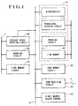
- Fig. 1 shows a block diagram of an overall facsimile apparatus in accordance with a first embodiment of the present invention.
- the decoding amount means the decoding time per line of the decoding circuit 60
- the printing amount means the printing time per line of the constant speed printer 80.
- numeral 10 denotes decoding time calculation circuit and compare circuit. It calculates the decoding time per line of the decoding circuit 60 and compares the calculated decoding time with the printing time.
- the decoding time calculation circuit 10 comprises a microcomputer 11 for controlling the overall facsimile system, as program and provisional decoding circuit 12.
- the provisional decoding circuit 12 has a function to decode the code and calculate the processing amount for decoding the code (for example, a time required for decoding, amount of code, amount of transition points of the pixel color, etc.).
- DICEP Document Image Compression and Expansion Processor
- Hitachi image processing LSI HD63085 a DICEP (Document Image Compression and Expansion Processor) which is a Hitachi image processing LSI HD63085.
- Numeral 20 denotes conversion circuit. It converts a line having a longer decoding time than the printing time to a provisional code such as a non-compression mode code.
- the conversion circuit 20 comprises a portion of the program of the microcomputer 11, encoding circuit 21 and a line memory 22.
- the line memory 22 stores the pixel signal decoded by the provisional decoding circuit 12.
- Numeral 30 denotes code memory circuit which stores the code converted by the conversion circuit 20.
- Numeral 40 denotes code receiving circuit which receives the coded document information sent from a transmitting facsimile system (not shown).
- the communication line c when it is a telephone network, it may comprise a NCU (network control unit) and a Modem (modulator/demodulator).
- Numeral 50 denotes a direct memory access controller (DMAC), which transports data between memories and I/O (Input/Output circuit) connected to a microcomputer bus a by the hardware without routing the processor in the microcomputer 11. The data transport is done at a high speed because the processor is not involved.
- the DMAC may be a commercially avialable LSI.
- Numeral 60 denotes decoding circuit which has a function to decode the code into pixels.
- the decoding circuit may be the same LSI as the processor of the provisional decoding circuit 12 although another processor may be used.
- Numeral 70 denotes pixel memory circuit which stores the pixel signal generated by the decoding circuit 60.
- the pixel memory circuit 70 usually has a memory capacity of two lines or more and it has a function of two-plane (two-port or dual port) buffer to parallelly store the pixel signal generated by the decoding circuit 60 and supply the stored pixel signal of other line to the constant speed printer 80.
- Numeral 80 denotes the constant speed printer which is an optical printer for printing a page line by line at a constant speed, a laser beam printer is usually used.
- the microcomputer 11 samples the code received by the code receiving circuit 40, transfers it to the provisional decoding circuit 12 and counts the amount of transferred code for each decoding unit.
- the provisional decoding means 12 decodes the input code into the pixels and supplies the generated pixels to the line memory 22. It detects the punctuation of the code between line and informs the end of decoding of one line to the microcomputer 11 (notice of end of decoding) .
- the provisional decoding circuit 12 parallelly carries out the error detection of the code when the microcomputer 11 receives the notice of end of decoding, it knows the amount of code of one line by calculating the amount of code transferred from the code receiving circuit 40 to the provisional decoding circuit 12.
- the decoding time can be readily calculated based on the amount of code by following the reverse process of the encoding process. Namely, the code is decoded by referring to the code table. The transition position of the pixel color is calculated based on the relative distance and the run length getting by decoding the code. And the original pixels are generated in accordance with the position data. Since the time required for carrying out such a process is previously known, the decoding time can be determined based on the amount of code.
- the microcomputer 11 compares the calculated decoding time with the printing time per line of the constant speed printer 80 to determine if the decoding time is longer or not, and depending on the comparison result, it commands the encoding circuit to change a decoding process, for example, to convert to other code.
- the decoding time If the decoding time is longer, it commands the encoding circuit 21 to encode the pixels by a non-compression mode, and otherwise it commands the encoding circuit 21 to encode the pixels by the MMR.
- the encoding circuit 21 encodes the pixel signals in the line memory 22 by using the encoding method designated by the microcomputer 11 and supplies the converted code to the code memory circuit 30.
- the code memory circuit 30 Since the code is converted to the other code before it is decoded for printing in order that the decoding time is not longer than the printing time, it is assured that the decoding time does not exceed the printing time.
- the microcomputer 11 When at least one page of converted code is supplied to the code memory circuit 30, the microcomputer 11 issues a decode command to the decoding circuit 60 and a one-page printing command to the constant speed printer 80.
- the microcomputer 11 issues a code transfer command to the direct memory controller (DMAC) 50 to transfer the code from the code memory circuit 30 to the decoding circuit 60.
- the decoding circuit 60 decodes the converted code into pixel signal and supplies the pixel signal to the pixel memory circuit 70.
- the constant speed printer 80 receives the pixel signal stored in the pixel memory circuit and prints one page of pixel signal line by line at the constant speed.
- the pixel memory circuit 70 has a capacity of storing at least two lines of pixel signal and functions as a two-plane buffer which permits the writing of the decoded pixels and the reading of the pixels to be printed, simultaneously.
- the decoding time per line is always shorter than the printing time. Accordingly, the two-line buffer is sufficient to store the pixels to be printed of the received coded document image and the effect of the small capacity memory and the constant speed printing is attained.
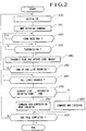
- Fig. 2 shows a process flow of the decoding time per line calculation and the conversion code determination by the microcomputer 11.
- a step 200 the initialization is carried out to clear a counter (code amount counter) which counts the amount of code per line.
- the decoding of the MMR code is commanded to the provisional decoding circuit 12.
- the provisional decoding circuit 12 starts the decoding of one line of MMR code in response to the command.
- step 220 whether the received code is present in the code receiving circuit 40 or not is determined. If the received code is present, whether the provisional decoding circuit 12 is ready to receive the code or not is determined (step 230). If it is ready, the code is transferred from the code receiving circuit 40 to the provisional decoding circuit 12 and the code amount counter is incremented by the amount of code transferred (step 240).
- step 250 whether the provisional decoding means has completed one line of decoding or not is determined. If one line of decoding has not yet been completed, the process returns to the step 220 and the steps 220 to 250 are repeated.
- step 260 whether the encoding means 21 has completed the coding of the previous line or not is determined. If it has not completed yet, the process waits until it is completed. When it is completed, the process proceeds to a step 270 to read out the code amount of one line from the code amount counter and calculate the decoding time of the decoded one line of code.
- the decoding time is compared with the preset printing per line of the constant speed printer 80, and if the decoding time is longer, the process proceeds to a step 290, and otherwise the process proceeds to a step 280.
- the MMR encoding command is issued to the encoding circuit 21 to convert one line of pixels stored in the line memory 22 to the MMR code.
- the non-compression mode encoding command is issued to the encoding circuit 21 to convert one line of pixels stored in the line memory 22 to the non-compression mode code.
- the code encoded in the steps 280 and 290 are stored in the code memory circuit 30.
- step 300 whether one page has been processed or not is determined (step 300), and if it is not yet processed, the process returns to the step 200 to repeat the above steps. Since the code is converted to the other code before decoding in order to prevent the decoding time from being longer than the printing time, the decoding time for each line does not exceed the printing time per line.
- the decoding time is calculated based on the amount of code and it is compared with the printing time.
- the amount of code corresponding to the printing time (the time converted code amount) may be preset and the time-converted code amount and the received code amount may be compared. In this method, the decoding time and the printing time are indirectly compared.
- the microcomputer 11 transfers the received code to the provisional decoding circuit 12. Alternatively, it may be done by the direct memory access controller (DMAC) 50. In this case, the amount of one line of code may be known from the amount of code transferred by the direct memory access controller (DMAC) 50. In the present embodiment, other commands issued by the microcomputer 11 are:
- the process to the next page of the document image can be executed even during the printing operation of the constant speed printer because the code transfer from the code memory circuit 30 to the decoding circuit 60 and the code transfer from the code memory circuit 30 to the provisional decoding circuit 12 can be parallelly done by time-sharing the microcomputer bus a .
- FIG. 1 A second embodiment which uses the amount of code per line as the decoding time is now explained.
- the numeral 10 in Fig. 1 is substituted by "code amount calculation circuit and compare circuit” and the function of the decoding circuit 60 is substituted by "it has a function of decoding the non-negative compression line within the printing time.
- the elements 20 to 80 are identical to those of Fig. 1, so the Figure is omitted in the drawing.
- the process to calculate the amount of one line of code is same as that in the Embodiment 1, but what is to be determined based on the amount of code is different from the Embodiment 1. Namely, whether it is the negative compression or not is determined. If it is the negative compression, it is determined that the decoding time is longer and the non-compression mode encoding is commanded to the encoding circuit 21, and otherwise the MMR encoding is commanded.
- the encoding circuit 21 encodes the pixels in the line memory 22 into the code in accordance with the command from the microcomputer 11 and supplies the converted code to the code memory circuit 30. The above process is repeated for the entire block (one page in the present embodiment) of the document image so that the non-negative compression codes for all lines are stored in the code memory circuit 30.
- the negative compression line of the MMR code (the amount of the code is three times that of the pixels at maximum) is converted to the non-compression mode, the following effects are attained compared to the decoding of the negative compression line in the printing time.
- the process flow of the microcomputer 11 is same as that of Fig. 2 if the function of the step 270 is substituted by "the decision as to whether it is the negative compression or not", so the Figure is omitted in the drawing.
- the negative compression decision step 270 the amount of one line of code is detected by referring the code amount counter to determine if it is the negative compression or not. If it is the negative compression, the process proceeds to a step 290, and otherwise the process proceeds to a step 280.
- the MMR encoding command is issued to the encoding circuit 21 to convert one line of pixels stored in the line memory 22 to the MMR code.
- the non-compression mode encoding command is issued to the encoding circuit 21 to convert one line of pixels stored in the line memory 22 to the non-compression mode code.
- the codes converted in the steps 280 and 290 are stored in the code memory circuit 30.
- a step 300 whether one page has been processed or not is determined, and if it has not been completed, the process returns to the step 200 to repeat the above steps. Through the above steps, there is no negative compression line in the code memory circuit 30. Thus, the page printing at the essentially constant speed can be attained without preparing a page memory which stores one page of pixels so long as the decoding circuit 60 which decodes the non-negative compression line in the printing time is provided.
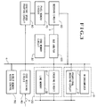
- Fig. 3 shows a third embodiment of the present embodiment.
- Circuit 10 to 80 are identical to those of Fig. 1 and the reference numerals and the explanation of the operations thereof are omitted.
- a code bus b is used to transfer the code from the code memory circuit 30 to the decoding circuit 60.
- Numeral 100 denotes a bus arbitor which is a bus switch to connect a bus which first accessed the code memory circuit 30 to the code memory circuit 30 to prevent the competition of access on the code memory circuit 30.
- the access from the code bus b has a higher priority.
- the processing of the decoding circuit 60 is given with a higher priority and the decoding for printing is attained at the high speed.
- the pixel memory circuit 70 is of two-plane (dual port) configuration so that the decoding means 60 can freely access the pixel memory circuit 70 even when the pixels are being supplied to the constant speed printer 80.
- the microcomputer 11 can convert the code at the high speed without being affected by the code transfer to the decoding circuit 60.
- the decoding means 60 can supply the decoded code to the pixel memory circuit 70 at the high speed even when the pixel signal is transferred from the pixel memory circuit 70 to the constant speed printer 80.
- the decoding time is approximately proportional to the number of transition points (transition point amount). Accordingly, the transition point amount per line may be used as the decoding amount.
- the circuit 10 in Fig. 1 is substituted by "transition point amount calculation circuit and compare circuit" and the function of the decoding circuit 60 is substituted by "it has a function to decode within the printing time the line whose transition point amount is less than a predetermined amount".
- the circuit 20 to 80 are identical to those of Fig. 1 and the explanation of those circuit is omitted.
- the transition point amount calculation circuit 13 calculates the transition point amount included in the transferred pixels.
- Embodiment 4 The operation of the Embodiment 4 is explained with reference to Fig. 4.
- the provisional decoding circuit 12 decodes the input code into the pixels and supplies the generated pixels to the line memory 22.
- the transition point amount calculation circuit 13 calculates the transition point amount in the generated pixels. After one line has been processed, the microcomputer 11 determines whether the transition point amount for one line calculated by the transition point amount calculation circuit 13 is larger than the predetermined transition point amount or not. If it is larger, it commands the non-compression mode encoding to the encoding circuit 21, and otherwise it commands the MMR encoding.
- the encoding circuit 21 converts the pixels in the line memory 22 in accordance with the command from the microcomputer 11 and supplies the converted code to the code memory circuit 30.
- the predetermined transition point amount is determined in accordance with the capability of the decoding circuit 60 and the printing speed of the constant speed printer 80 so that it is assured that the decoding circuit 60 decodes the converted code stored in the code memory circuit 30 within the printing time.
- the code memory circuit 30 now stores the codes which the decoding circuit 60 can decode within the printing time for each line.
- the buffer for storing the decoded pixels of the coded document image for printing may be one-line buffer and the essentially constant speed printing is attained with the small capacity pixel memory.
- the transition point amount calculation circuit 13 has a function to compare the transition point amount with a predetermined value and a function to supply the comparison result directly to the encoding circuit 21 through a signal line d , and the encoding circuit 21 encodes the pixels by either the non-compression mode or the MMR in accordance with the comparison result supplied from the signal line d .
- the predetermined value is set in a register in the transition point amount calculation circuit 13 by the microcomputer 11.
- the comparison process of the transition point amount and the predetermine value by the microcomputer 11 and the encoding command process for each line to the encoding circuit 21 by the microcomputer 11 in accordance with the comparison result are eliminated so that the load to the microcomputer is reduced and the code conversion process speed is increased.
- a process flow of the microcomputer 11 in the embodiment 5 is identical to that of Fig. 2 when the function of the step 240 in Fig. 2 is substituted by the transfer of the code and the function of the step 270 is substituted by the determination as to whether the transition point amount exceeds the predetermined value or not, and hence it is not shown.
- the transition point amount calculation circuit 13 is referred to read the transition point amount for one line to determine whether the transition point amount is larger than the predetermined value or not. If it is larger, the process proceeds to the step 290, and otherwise it proceeds to the step 280.
- the MMR encoding command is issued to the encoding circuit 21 to convert one line of pixels stored in the line memory 22 to the MMR code.
- the non-compression mode encoding command is issued to the encoding circuit 21 to convert one line of pixels stored in the line memory 22 to the non-compression mode code.
- the code converted in the step 280 or 290 is stored in the memory circuit 30.
- the above process is repeated for one page of lines.
- the line having the transition point amount larger than the predetermined value is converted to the non-compression code and it is stored in the memory circuit 30.
- the circuit 10 to 100 are identical to those of Fig. 3 when the code receiving circuit 40 and the communication line c are substituted by the encoded document file (the same reference numerals as those of Fig. 3 are used herein), and the drawing, the explanation of the reference numerals and the operation thereof are omitted.
- the encoded document file 40 is a memory medium which stores the encoded document. Examples of the memory medium are a floppy disk, a hard disk and an optical disk.
- the code is read from the encoded document file 40, it is transferred to the encoding circuit 21, the code is converted to other code by the series of process described in the previous embodiment so that the decoding time per line is shorter than the printing time, and the converted code is stored in the code memory circuit 30.
- the decoding circuit 60 decodes the code stored in the code memory circuit 30 and supplies it to the pixel memory circuit 70.
- the constant speed printer 80 reads the pixels from the pixel memory circuit 70 and prints them at the constant speed.
- the encoded document stored in the memory medium can be printed at the essentially constant speed without using the page memory.
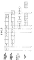
- Fig. 5 shows a time chart of the processes shown in Figs. 1, 2, 3 and 4. The direction of the time elapse of the process is from left to right on the drawing.
- the time chart shows the process for two pages of document image.
- the provisional decoding circuit 12 starts the provisional decoding step 400 for the first line of the first page.
- the encoding circuit 21 starts the conversion encoding step 410 for the first line of the first page.
- the provisional decoding process 400 for the first page is completed at a time t 3 , and the provisional decoding process for the first line of the second page is started.
- the conversion encoding step 410 for the first page is completed at a time t 4 and the conversion encoding step for the first line of the second page is started.
- the decoding circuit 60 starts the decoding step 420 for the first line of the first page.
- the constant speed printer 80 starts the printing step 430 for the first line of the first page, and the printing step 430 for the first page is completed at a time t 6 .
- the decoding step 420 and the printing step 430 for the second page are shown only partially for simplification purpose, but they are continuously executed.
- the processing time is further shortened and the entire processing speed is increased.
- the facsimile apparatus normally has scanner circuit which scans a document and generates the electrical image signal. If the image information is in the form of electrical signal, the scanner circuit is not necessary.
- An example is where an image processed by a personal computer is to be transmitted as image informaiton.
- the video signal processing circuit 320 executes video signal processing (for example high-precision shading distortion correction) on the electrical image signal and generates the pixel signal, and the pixel signal is compressed by the encoding circuit 330 and temporarily stored in the code memory circuit (encoded document file) 340. It is then sent to the transmission line by the modulation/transmission controller 345 in accordance with the communication protocol.
- the code transmitted to the destination facsimile apparatus (receiving station) through the transmission line is decoded to the original pixel by the reverse process to that in the transmitting station.
- the reproduced image data (the original pixel) is printed on a sheet by the printer 80.
- the code decoding time does not exceed the printing time so that the document image sent from the sending station can be printed without interrupting the printing operation.
- the document scanning operation at the sending station and the document printing operation at the receiving station are executed timingly, the document send operation and the utilization of the transmission line are efficiently done and the overall system operates smoothly without waste because the suspension by the trouble such as fullness of the facsimile system line.
- the decoding time may follow the printing time of the printing unit, the printing may be completed in a shorter time if a high speed printing unit is used. So that high speed facsimile document transmission/reception is attained and the attendants at the sending station and the receiving station can save time. For example, if a document of size A4 is read in one second and the facsimile apparatus at the receiving station has a plain paper printing unit having a printing speed of 60 sheets per minute for the same size, the document is printed in approximately one second because the encoding/decoding time and the transmission time are very small. Thus, a real time transmission facsimile system is attained so that the document scanned at the sending station is printed at the receiving station essentially simultaneously with the completion of the document scanning.
- the code is temporarily converted to the other code (provisionally converted code) to prevent the decoding time from being longer than the printing time so that it is assured that the decoding time does not exceed the printing time.
- This principle is applied to the facsimile apparatus at the destination station (receiving station).
- the provisionally converted code whose decoding time does not exceed the printing time is transmitted as it is, and the receiving station receives the provisionally converted code as it is and decodes it as it is without modifying the code.
- Fig. 7 shows a facsimile system which uses the above principle and shows a flow of the above communication.
- the notice of provisional signal is sent to the receiving station with the code data as status information 355 so that the apparatus at the sending station and the receiving station can recognize that whether the code just sent is the provisional code or not.
- Such a convention is needed only between the sending station and the receiving station without regard to the type and the manufacturers of the apparatus.
- the encoded image block which cannot be decoded in the printing time is converted to the code which can be decoded in the printing time of the image block. Accordingly:
Landscapes
- Engineering & Computer Science (AREA)
- Multimedia (AREA)
- Signal Processing (AREA)
- Compression Of Band Width Or Redundancy In Fax (AREA)
- Image Processing (AREA)
Description
- The present invention relates to a method and an apparatus for printing a pixel signal. The invention relates in particular to a coded image printing method and apparatus such as a facsimile apparatus for processing a document image with high speed.
- Prior art to the present invention includes:
DENSHI GIJUTSU (Electronic Technology) April 1988 (pages 64 - 70) "Introduction of ASIC Observed in an Ultra-High Speed Facsimile Apparatus". - In the prior art facsimile apparatus described above which uses a printing system (for example, a laser beam printer) to be printed at a constant speed, a high speed decoding processor is required in order to decode a signal in a shorter process time than a print time.
- More particularly, even if the amount of code for a particular line after the encoding is larger than the amount of pixels prior to the encoding so that a compression effect by the encoding is negative (negative compression), it is necessary to decode that line faster than the printing time of that line. To this end, a very high speed decoding processor is required.
- Prior art document WO-A-83 03487 discloses a page printing system. This system processes high level encoded page layout information to form a printed page. An image processor operates to form page image data, at a variable rate, during processing time. A window buffer is filled at a rate at which the image processor processes the page layout information.
- The rate at which the window buffer is emptied, to supply page image data to a printing device, is determined by the rate of printing of the printing device. The printer, operating at a preestablished printing rate, prints the printed page during a printing time. The variable rate of the image processor is determined such that that the duration of the processing time does not exceed the duration of the printing time.
- Prior art document DE-A-31 37 903 discloses a facsimile apparatus. The receiving unit comprises a memory of a capacity suitable for at least one page of information. It further comprises a clock generator for generating a clock for reading out the received information signal stored in the memory. A converting circuit converts the information read out from the memory in analog signal and a printing device printing with constant speed using the produced analog signal. The memory is responsive to the generated clock signal in such a manner that information signals are continuously read out such that scanning start timing for each scanning line is repeated with a constant period.
- It is an object of the present invention to provide an apparatus which decodes a coded image at a speed higher than the printing speed so that the coded image is printed without being restricted by the time required for decoding.
- This object is solved in accordance with the features of the independent claims. Dependent claims are directed on preferred embodiments of the invention.
- In the method for printing the pixels generated by decoding the coded image, the decoding time for the coded image signal is calculated for each decoding and/or printing process unit, and the code is changed to another code if the calculated decoding time is longer than the printing time.
- In accordance with the present invention, there is provided a coded image printing apparatus carrying out the above method. Such an apparatus may comprise
- (a) provisional decoding circuit for decoding the coded image signal into pixels for each decoding and/or printing process unit;
- (b) count circuit for counting the code amount or the transition point amount of the pixel color signal of each decoding and/or printing process unit;
- (c) calculation circuit for calculating the decoding amount of each decoding and/or printing process unit based on the code amount or the transition point amount counted by said count circuit;
- (d) compare circuit for comparing the calculated decoding amount with the printing amount required to print the pixels;
- (e) conversion circuit for converting the code into other code when the calculated decoding amount is larger than the printing amount;
- (f) first memory circuit for storing the code converted by said conversion circuit;
- (g) decoding circuit for decoding the code stored in said first memory circuit to pixels;
- (h) second memory circuit for storing the pixels decoded by said decoding circuit; and
- (i) printer for printing the pixels stored in said second memory circuit.
- The decoding amount-calculation circuit calculates the amount of decoding of the code to be decoded, and the compare circuit determines whether the decoding amount exceeds the printing amount of pixels to be printed. The conversion circuit converts the code into the other code when the calculated decoding amount is larger than the printing amount. The converted code is stored in the code memory circuit. The decoding circuit receives the converted code from the code memory circuit, decodes it to the pixel information and supplies it to the pixel memory circuit. The stored pixels are supplied to the printer for printing.
- In the receiving station apparatus to which the document is transmitted by the circuit for encoding to the provisional conversion code, the code which is previously known that the decoding time does not exceed the printing time is decoded without converting other code.
-
- Fig. 1 shows a block diagram of one embodiment of the present invention.
- Fig. 2 shows a process flow chart of a microcomputer 11,
- Fig. 3 shows a block diagram of another embodiment of the present invention,
- Fig. 4 shows a block diagram of a third embodiment of the present invention,
- Fig. 5 shows a time chart for a processing time in the present invention,
- Fig. 6 shows one embodiment in which the present invention is applied to a facsimile system, and
- Fig. 7 shows another embodiment in which the present invention is applied to the facsimile system.
- In the following embodiments, the following assumption is made in order to make the explanation simpler although it is not restrictive. It is assumed that a code prior to the conversion is the MMR code which is most complex and takes a longest decoding time 5 among the MH code, the MR code and the MMR code which are the international standard codes defined by the CCITT Recommendations T.4 and T.6 applied to the facsimile system. It is assumed that a code after the code conversion is a non-compression mode code which is a simplest code and takes a shortest decoding time. Constant speed printer is an optical printer (laser beam printer). Since the laser beam printer is a constant speed printing system for each line to be printed and the decoding process is performed line by line, it is assumed that a block which is a unit for processing the image to be encoded and decoded is a line.
- Fig. 1 shows a block diagram of an overall facsimile apparatus in accordance with a first embodiment of the present invention.
- In the
present embodiment 1, it is assumed that the decoding amount means the decoding time per line of thedecoding circuit 60, and the printing amount means the printing time per line of theconstant speed printer 80. In Fig. 1,numeral 10 denotes decoding time calculation circuit and compare circuit. It calculates the decoding time per line of thedecoding circuit 60 and compares the calculated decoding time with the printing time. The decodingtime calculation circuit 10 comprises a microcomputer 11 for controlling the overall facsimile system, as program andprovisional decoding circuit 12. Theprovisional decoding circuit 12 has a function to decode the code and calculate the processing amount for decoding the code (for example, a time required for decoding, amount of code, amount of transition points of the pixel color, etc.). It may be implemented by a DICEP (Document Image Compression and Expansion Processor) which is a Hitachi image processing LSI HD63085. Numeral 20 denotes conversion circuit. It converts a line having a longer decoding time than the printing time to a provisional code such as a non-compression mode code. Theconversion circuit 20 comprises a portion of the program of the microcomputer 11, encodingcircuit 21 and aline memory 22. Theline memory 22 stores the pixel signal decoded by theprovisional decoding circuit 12. Numeral 30 denotes code memory circuit which stores the code converted by theconversion circuit 20.Numeral 40 denotes code receiving circuit which receives the coded document information sent from a transmitting facsimile system (not shown). For example, when the communication line c is a telephone network, it may comprise a NCU (network control unit) and a Modem (modulator/demodulator).Numeral 50 denotes a direct memory access controller (DMAC), which transports data between memories and I/O (Input/Output circuit) connected to a microcomputer bus a by the hardware without routing the processor in the microcomputer 11. The data transport is done at a high speed because the processor is not involved. The DMAC may be a commercially avialable LSI.Numeral 60 denotes decoding circuit which has a function to decode the code into pixels. The decoding circuit may be the same LSI as the processor of theprovisional decoding circuit 12 although another processor may be used.Numeral 70 denotes pixel memory circuit which stores the pixel signal generated by thedecoding circuit 60. Thepixel memory circuit 70 usually has a memory capacity of two lines or more and it has a function of two-plane (two-port or dual port) buffer to parallelly store the pixel signal generated by thedecoding circuit 60 and supply the stored pixel signal of other line to theconstant speed printer 80.Numeral 80 denotes the constant speed printer which is an optical printer for printing a page line by line at a constant speed, a laser beam printer is usually used. - The operation of the
embodiment 1 is now explained. The microcomputer 11 samples the code received by thecode receiving circuit 40, transfers it to theprovisional decoding circuit 12 and counts the amount of transferred code for each decoding unit. The provisional decoding means 12 decodes the input code into the pixels and supplies the generated pixels to theline memory 22. It detects the punctuation of the code between line and informs the end of decoding of one line to the microcomputer 11 (notice of end of decoding) . Theprovisional decoding circuit 12 parallelly carries out the error detection of the code when the microcomputer 11 receives the notice of end of decoding, it knows the amount of code of one line by calculating the amount of code transferred from thecode receiving circuit 40 to theprovisional decoding circuit 12. The decoding time can be readily calculated based on the amount of code by following the reverse process of the encoding process. Namely, the code is decoded by referring to the code table. The transition position of the pixel color is calculated based on the relative distance and the run length getting by decoding the code. And the original pixels are generated in accordance with the position data. Since the time required for carrying out such a process is previously known, the decoding time can be determined based on the amount of code. The microcomputer 11 compares the calculated decoding time with the printing time per line of theconstant speed printer 80 to determine if the decoding time is longer or not, and depending on the comparison result, it commands the encoding circuit to change a decoding process, for example, to convert to other code. If the decoding time is longer, it commands theencoding circuit 21 to encode the pixels by a non-compression mode, and otherwise it commands theencoding circuit 21 to encode the pixels by the MMR. Theencoding circuit 21 encodes the pixel signals in theline memory 22 by using the encoding method designated by the microcomputer 11 and supplies the converted code to thecode memory circuit 30. When the above process is completed to the block of the document image, for example, one page, the code of all lines has been stored in thecode memory circuit 30. Since the code is converted to the other code before it is decoded for printing in order that the decoding time is not longer than the printing time, it is assured that the decoding time does not exceed the printing time. When at least one page of converted code is supplied to thecode memory circuit 30, the microcomputer 11 issues a decode command to thedecoding circuit 60 and a one-page printing command to theconstant speed printer 80. The microcomputer 11 issues a code transfer command to the direct memory controller (DMAC) 50 to transfer the code from thecode memory circuit 30 to thedecoding circuit 60. Thedecoding circuit 60 decodes the converted code into pixel signal and supplies the pixel signal to thepixel memory circuit 70. Theconstant speed printer 80 receives the pixel signal stored in the pixel memory circuit and prints one page of pixel signal line by line at the constant speed. Thepixel memory circuit 70 has a capacity of storing at least two lines of pixel signal and functions as a two-plane buffer which permits the writing of the decoded pixels and the reading of the pixels to be printed, simultaneously. - In accordance with the present embodiment, it is assured that the decoding time per line is always shorter than the printing time. Accordingly, the two-line buffer is sufficient to store the pixels to be printed of the received coded document image and the effect of the small capacity memory and the constant speed printing is attained.
- Fig. 2 shows a process flow of the decoding time per line calculation and the conversion code determination by the microcomputer 11.
- In a
step 200, the initialization is carried out to clear a counter (code amount counter) which counts the amount of code per line. In astep 200, the decoding of the MMR code is commanded to theprovisional decoding circuit 12. Thus, theprovisional decoding circuit 12 starts the decoding of one line of MMR code in response to the command. Then, whether the received code is present in thecode receiving circuit 40 or not is determined (step 220). If the received code is present, whether theprovisional decoding circuit 12 is ready to receive the code or not is determined (step 230). If it is ready, the code is transferred from thecode receiving circuit 40 to theprovisional decoding circuit 12 and the code amount counter is incremented by the amount of code transferred (step 240). Then, whether the provisional decoding means has completed one line of decoding or not is determined (step 250). If one line of decoding has not yet been completed, the process returns to thestep 220 and thesteps 220 to 250 are repeated. When one line of decoding is completed, the process proceeds to astep 260. In thestep 260, whether the encoding means 21 has completed the coding of the previous line or not is determined. If it has not completed yet, the process waits until it is completed. When it is completed, the process proceeds to astep 270 to read out the code amount of one line from the code amount counter and calculate the decoding time of the decoded one line of code. The decoding time is compared with the preset printing per line of theconstant speed printer 80, and if the decoding time is longer, the process proceeds to astep 290, and otherwise the process proceeds to astep 280. In thestep 280, the MMR encoding command is issued to theencoding circuit 21 to convert one line of pixels stored in theline memory 22 to the MMR code. In astep 290, the non-compression mode encoding command is issued to theencoding circuit 21 to convert one line of pixels stored in theline memory 22 to the non-compression mode code. The code encoded in thesteps code memory circuit 30. Then, whether one page has been processed or not is determined (step 300), and if it is not yet processed, the process returns to thestep 200 to repeat the above steps. Since the code is converted to the other code before decoding in order to prevent the decoding time from being longer than the printing time, the decoding time for each line does not exceed the printing time per line. - In the
step 270, the decoding time is calculated based on the amount of code and it is compared with the printing time. Alternatively, the amount of code corresponding to the printing time (the time converted code amount) may be preset and the time-converted code amount and the received code amount may be compared. In this method, the decoding time and the printing time are indirectly compared. - In the present embodiment, the microcomputer 11 transfers the received code to the
provisional decoding circuit 12. Alternatively, it may be done by the direct memory access controller (DMAC) 50. In this case, the amount of one line of code may be known from the amount of code transferred by the direct memory access controller (DMAC) 50. In the present embodiment, other commands issued by the microcomputer 11 are: - ① a decoding command issued to the
decoding circuit 60 when one page of converted code is stored in thecode memory circuit 30. - ② a print command issued to the
constant speed printer 80. - ③ a code transfer command to transfer the code from the
code memory circuit 30 to thedecoding circuit 60, issued to the direct memory access controller (DMAC) 50. - The above process flow, among others the process to the next page of the document image can be executed even during the printing operation of the constant speed printer because the code transfer from the
code memory circuit 30 to thedecoding circuit 60 and the code transfer from thecode memory circuit 30 to theprovisional decoding circuit 12 can be parallelly done by time-sharing the microcomputer bus a. - A second embodiment which uses the amount of code per line as the decoding time is now explained. The numeral 10 in Fig. 1 is substituted by "code amount calculation circuit and compare circuit" and the function of the
decoding circuit 60 is substituted by "it has a function of decoding the non-negative compression line within the printing time. Theelements 20 to 80 are identical to those of Fig. 1, so the Figure is omitted in the drawing. - The operation of the
embodiment 2 is explained with the substituted Fig. 1. - The process to calculate the amount of one line of code is same as that in the
Embodiment 1, but what is to be determined based on the amount of code is different from theEmbodiment 1. Namely, whether it is the negative compression or not is determined. If it is the negative compression, it is determined that the decoding time is longer and the non-compression mode encoding is commanded to theencoding circuit 21, and otherwise the MMR encoding is commanded. Theencoding circuit 21 encodes the pixels in theline memory 22 into the code in accordance with the command from the microcomputer 11 and supplies the converted code to thecode memory circuit 30. The above process is repeated for the entire block (one page in the present embodiment) of the document image so that the non-negative compression codes for all lines are stored in thecode memory circuit 30. - In the present embodiment, since the negative compression line of the MMR code (the amount of the code is three times that of the pixels at maximum) is converted to the non-compression mode, the following effects are attained compared to the decoding of the negative compression line in the printing time.
- ① The decoding time is reduced to below 1/3 at maximum.
- ② There is no need for providing a one-page pixel memory (page memory).
- ③ Essentially constant speed printing is attained by only the two-line pixel printing buffer.
- ④ The memory capacity of the
code memory circuit 30 is reduced to 1/3 at maximum. - ⑤ The time to transfer the code from the
code memory circuit 30 to theencoding circuit 60 through the microcomputer bus a is reduced to 1/3 at maximum, compared to the case where the code is not converted to the non-compression mode code. - ⑥ The load of the microcomputer bus a for the code transfer is reduced to 1/3 at maximum.
- The operation of the
embodiment 2 is now explained. - The process flow of the microcomputer 11 is same as that of Fig. 2 if the function of the
step 270 is substituted by "the decision as to whether it is the negative compression or not", so the Figure is omitted in the drawing. In the negativecompression decision step 270, the amount of one line of code is detected by referring the code amount counter to determine if it is the negative compression or not. If it is the negative compression, the process proceeds to astep 290, and otherwise the process proceeds to astep 280. In thestep 280, the MMR encoding command is issued to theencoding circuit 21 to convert one line of pixels stored in theline memory 22 to the MMR code. In thestep 290, the non-compression mode encoding command is issued to theencoding circuit 21 to convert one line of pixels stored in theline memory 22 to the non-compression mode code. The codes converted in thesteps code memory circuit 30. In astep 300, whether one page has been processed or not is determined, and if it has not been completed, the process returns to thestep 200 to repeat the above steps. Through the above steps, there is no negative compression line in thecode memory circuit 30. Thus, the page printing at the essentially constant speed can be attained without preparing a page memory which stores one page of pixels so long as thedecoding circuit 60 which decodes the non-negative compression line in the printing time is provided. - Fig. 3 shows a third embodiment of the present embodiment.
Circuit 10 to 80 are identical to those of Fig. 1 and the reference numerals and the explanation of the operations thereof are omitted. A code bus b is used to transfer the code from thecode memory circuit 30 to thedecoding circuit 60.Numeral 100 denotes a bus arbitor which is a bus switch to connect a bus which first accessed thecode memory circuit 30 to thecode memory circuit 30 to prevent the competition of access on thecode memory circuit 30. When both the microcomputer bus a and the code bus b simultaneously access the code memory circuit, the access from the code bus b has a higher priority. Thus, the processing of thedecoding circuit 60 is given with a higher priority and the decoding for printing is attained at the high speed. In the present embodiment, thepixel memory circuit 70 is of two-plane (dual port) configuration so that the decoding means 60 can freely access thepixel memory circuit 70 even when the pixels are being supplied to theconstant speed printer 80. - In accordance with the Embodiment 3, since the code bus b is separated from the microcomputer bus a, the microcomputer 11 can convert the code at the high speed without being affected by the code transfer to the
decoding circuit 60. - In accordance with the Embodiment 3, since the
pixel memory circuit 70 is of dual port configuration, the decoding means 60 can supply the decoded code to thepixel memory circuit 70 at the high speed even when the pixel signal is transferred from thepixel memory circuit 70 to theconstant speed printer 80. - An embodiment which uses the number of transition points of the pixel color per line as the decoding amount is explained with reference to Fig. 4.
- In the MH code, the MR code and the MMR code, the transition points at which the pixels generated by scanning the document from left to right change from black pixel to white pixel or from white pixel to black pixel are encoded. Accordingly, the decoding time is approximately proportional to the number of transition points (transition point amount). Accordingly, the transition point amount per line may be used as the decoding amount.
- The
circuit 10 in Fig. 1 is substituted by "transition point amount calculation circuit and compare circuit" and the function of thedecoding circuit 60 is substituted by "it has a function to decode within the printing time the line whose transition point amount is less than a predetermined amount". Thecircuit 20 to 80 are identical to those of Fig. 1 and the explanation of those circuit is omitted. When theprovisional decoding circuit 12 transfers the decoded pixels to theline memory 22, the transition pointamount calculation circuit 13 calculates the transition point amount included in the transferred pixels. - The operation of the Embodiment 4 is explained with reference to Fig. 4.
- The
provisional decoding circuit 12 decodes the input code into the pixels and supplies the generated pixels to theline memory 22. The transition pointamount calculation circuit 13 calculates the transition point amount in the generated pixels. After one line has been processed, the microcomputer 11 determines whether the transition point amount for one line calculated by the transition pointamount calculation circuit 13 is larger than the predetermined transition point amount or not. If it is larger, it commands the non-compression mode encoding to theencoding circuit 21, and otherwise it commands the MMR encoding. Theencoding circuit 21 converts the pixels in theline memory 22 in accordance with the command from the microcomputer 11 and supplies the converted code to thecode memory circuit 30. The predetermined transition point amount is determined in accordance with the capability of thedecoding circuit 60 and the printing speed of theconstant speed printer 80 so that it is assured that thedecoding circuit 60 decodes the converted code stored in thecode memory circuit 30 within the printing time. When the above process is completed for the entire page, thecode memory circuit 30 now stores the codes which thedecoding circuit 60 can decode within the printing time for each line. - In accordance with the present embodiment, since it is assured that the decoding time per line is always shorter than the printing time, the buffer for storing the decoded pixels of the coded document image for printing may be one-line buffer and the essentially constant speed printing is attained with the small capacity pixel memory.
- In a modification of the present embodiment, the transition point
amount calculation circuit 13 has a function to compare the transition point amount with a predetermined value and a function to supply the comparison result directly to theencoding circuit 21 through a signal line d, and theencoding circuit 21 encodes the pixels by either the non-compression mode or the MMR in accordance with the comparison result supplied from the signal line d. The predetermined value is set in a register in the transition pointamount calculation circuit 13 by the microcomputer 11. In accordance with the present embodiment, the comparison process of the transition point amount and the predetermine value by the microcomputer 11 and the encoding command process for each line to theencoding circuit 21 by the microcomputer 11 in accordance with the comparison result are eliminated so that the load to the microcomputer is reduced and the code conversion process speed is increased. - An operation of the Embodiment 5 is now explained.
- A process flow of the microcomputer 11 in the embodiment 5 is identical to that of Fig. 2 when the function of the
step 240 in Fig. 2 is substituted by the transfer of the code and the function of thestep 270 is substituted by the determination as to whether the transition point amount exceeds the predetermined value or not, and hence it is not shown. In thestep 270 to determine the transition point amount, the transition pointamount calculation circuit 13 is referred to read the transition point amount for one line to determine whether the transition point amount is larger than the predetermined value or not. If it is larger, the process proceeds to thestep 290, and otherwise it proceeds to thestep 280. In thestep 280, the MMR encoding command is issued to theencoding circuit 21 to convert one line of pixels stored in theline memory 22 to the MMR code. In thestep 290, the non-compression mode encoding command is issued to theencoding circuit 21 to convert one line of pixels stored in theline memory 22 to the non-compression mode code. The code converted in thestep memory circuit 30. The above process is repeated for one page of lines. Through the above process, the line having the transition point amount larger than the predetermined value is converted to the non-compression code and it is stored in thememory circuit 30. Thus, by providing thedecoding circuit 60 which can decode at least those lines having the transition point amount smaller than the predetermined value, within the recording time, the constant speed printing for each page is attained without providing a page memory which can store one page of pixels. - A sixth embodiment of the present invention is now explained. The
circuit 10 to 100 are identical to those of Fig. 3 when thecode receiving circuit 40 and the communication line c are substituted by the encoded document file (the same reference numerals as those of Fig. 3 are used herein), and the drawing, the explanation of the reference numerals and the operation thereof are omitted. The encodeddocument file 40 is a memory medium which stores the encoded document. Examples of the memory medium are a floppy disk, a hard disk and an optical disk. The code is read from the encodeddocument file 40, it is transferred to theencoding circuit 21, the code is converted to other code by the series of process described in the previous embodiment so that the decoding time per line is shorter than the printing time, and the converted code is stored in thecode memory circuit 30. Thedecoding circuit 60 decodes the code stored in thecode memory circuit 30 and supplies it to thepixel memory circuit 70. Theconstant speed printer 80 reads the pixels from thepixel memory circuit 70 and prints them at the constant speed. - In accordance with the Embodiment 6, the encoded document stored in the memory medium can be printed at the essentially constant speed without using the page memory.
- Fig. 5 shows a time chart of the processes shown in Figs. 1, 2, 3 and 4. The direction of the time elapse of the process is from left to right on the drawing. The time chart shows the process for two pages of document image. At a time t1, the
provisional decoding circuit 12 starts theprovisional decoding step 400 for the first line of the first page. When theprovisional decoding step 400 for the first line of the first page is completed at a time t2, theencoding circuit 21 starts theconversion encoding step 410 for the first line of the first page. Theprovisional decoding process 400 for the first page is completed at a time t3, and the provisional decoding process for the first line of the second page is started. Theconversion encoding step 410 for the first page is completed at a time t4 and the conversion encoding step for the first line of the second page is started. At the time t4, thedecoding circuit 60 starts thedecoding step 420 for the first line of the first page. When thedecoding step 420 for the first line of the first page is completed at a time t5, theconstant speed printer 80 starts theprinting step 430 for the first line of the first page, and theprinting step 430 for the first page is completed at a time t6. In the time chart, thedecoding step 420 and theprinting step 430 for the second page are shown only partially for simplification purpose, but they are continuously executed. - Since the
provisional decoding step 400, theconversion encoding step 410, thedecoding step 420 and theprinting step 430 are executed parallelly, the processing time is further shortened and the entire processing speed is increased. - The application of the present invention to a facsimile apparatus or a facsimile system is now explained with reference to Fig. 6.
- The facsimile apparatus normally has scanner circuit which scans a document and generates the electrical image signal. If the image information is in the form of electrical signal, the scanner circuit is not necessary. An example is where an image processed by a personal computer is to be transmitted as image informaiton. At a source station (sending station) which transmits a document, the video
signal processing circuit 320 executes video signal processing (for example high-precision shading distortion correction) on the electrical image signal and generates the pixel signal, and the pixel signal is compressed by theencoding circuit 330 and temporarily stored in the code memory circuit (encoded document file) 340. It is then sent to the transmission line by the modulation/transmission controller 345 in accordance with the communication protocol. The code transmitted to the destination facsimile apparatus (receiving station) through the transmission line is decoded to the original pixel by the reverse process to that in the transmitting station. The reproduced image data (the original pixel) is printed on a sheet by theprinter 80. In accordance with the Embodiment 7, when the present invention is used as the receiving station, the code decoding time does not exceed the printing time so that the document image sent from the sending station can be printed without interrupting the printing operation. Further, since the document scanning operation at the sending station and the document printing operation at the receiving station are executed timingly, the document send operation and the utilization of the transmission line are efficiently done and the overall system operates smoothly without waste because the suspension by the trouble such as fullness of the facsimile system line. Further, since the decoding time may follow the printing time of the printing unit, the printing may be completed in a shorter time if a high speed printing unit is used. So that high speed facsimile document transmission/reception is attained and the attendants at the sending station and the receiving station can save time. For example, if a document of size A4 is read in one second and the facsimile apparatus at the receiving station has a plain paper printing unit having a printing speed of 60 sheets per minute for the same size, the document is printed in approximately one second because the encoding/decoding time and the transmission time are very small. Thus, a real time transmission facsimile system is attained so that the document scanned at the sending station is printed at the receiving station essentially simultaneously with the completion of the document scanning. - Another application of the present invention to the facsimile system is now explained with reference to Fig. 7.
- In the
Embodiment 1, the code is temporarily converted to the other code (provisionally converted code) to prevent the decoding time from being longer than the printing time so that it is assured that the decoding time does not exceed the printing time. This principle is applied to the facsimile apparatus at the destination station (receiving station). At the document sending station, the provisionally converted code whose decoding time does not exceed the printing time is transmitted as it is, and the receiving station receives the provisionally converted code as it is and decodes it as it is without modifying the code. Fig. 7 shows a facsimile system which uses the above principle and shows a flow of the above communication. The notice of provisional signal is sent to the receiving station with the code data asstatus information 355 so that the apparatus at the sending station and the receiving station can recognize that whether the code just sent is the provisional code or not. Such a convention is needed only between the sending station and the receiving station without regard to the type and the manufacturers of the apparatus. - In accordance with the present invention, the encoded image block which cannot be decoded in the printing time is converted to the code which can be decoded in the printing time of the image block. Accordingly:
- ①No high speed decoding circuit is required for decoding the non-converted code in the printing time.
- ②No memory is required for storing one page of pixel signal.
- ③ The constant speed printing of the encoded document is attained.
- ④ The cost of the constant speed printing unit is reduced.
- ⑤The encoded document can be efficiently stored in the memory because the negative compressed image block is converted to the non-compression mode code.
- ⑥Since the document is encoded to the provisionally converted code at the sending station and the notice of conversion and the provisional code are sent to the receiving station, it is not necessary for the receiving station to compare the decoding time and the printing time or reconvert the code to the provisional code, the processing time is shortened.
Claims (6)
- A method of printing a pixel signal obtained by decoding a coded image signal, comprising the steps of:calculating the decoding time required to decode the coded image signal for each decoding and/or printing process unit;comparing the calculated decoding time with the printing time required to print the pixels (step 270); andconverting the coded image signal in a decoding and/or printing process unit to a different code of shorter decoding time, when the calculated decoding time is larger than the printing time (step 290).
- A method according to claim 1, further comprising the step of counting the amount of code in said coded image signal for each decoding and/or printing process unit, wherein the step of calculating the decoding time comprises the step of calculating the decoding time on the basis of the counted amount of the code in said coded image signal.
- A method according to claim 1, further comprising the step of counting the amount of color transition points of the pixel signals for each decoding and/or printing process unit, wherein the step of calculating the decoding time comprises the step of calculating the decoding time on the basis of the counted amount of the transition points.
- A printing apparatus for printing a pixel signal obtained by decoding a coded image signal, comprising:means for calculating the decoding time required to decode the coded image signal for each decoding and/or printing process unit;means for comparing the calculated decoding time with the printing time required to print the pixel signals; andmeans for converting the coded image signal in a decoding and/or printing process unit to a different code of shorter decoding time, when the calculated decoding time is larger than the printing time.
- A printing apparatus according to claim 4, further comprising means for counting the amount of code in the coded image signal for each decoding and/or printing process unit, wherein the calculating means comprises means for calculating the decoding time on the basis of the counted amount of the code in the coded image signal.
- A printing apparatus according to claim 4, further comprising means for counting the amount of color transition points of the pixel signals for each decoding and/or printing process unit, wherein the calculating means comprises means for calculating the decoding time on the basis of the counted amount of the transition points.
Applications Claiming Priority (4)
| Application Number | Priority Date | Filing Date | Title |
|---|---|---|---|
| JP329059/90 | 1990-11-30 | ||
| JP32905990 | 1990-11-30 | ||
| JP3118346A JPH04229768A (en) | 1990-11-30 | 1991-05-23 | Coding picture recording device, facsimile equipment using the device, optical file device and communication system for them |
| JP118346/91 | 1991-05-23 |
Publications (3)
| Publication Number | Publication Date |
|---|---|
| EP0488274A2 EP0488274A2 (en) | 1992-06-03 |
| EP0488274A3 EP0488274A3 (en) | 1992-09-16 |
| EP0488274B1 true EP0488274B1 (en) | 1996-07-24 |
Family
ID=26456304
Family Applications (1)
| Application Number | Title | Priority Date | Filing Date |
|---|---|---|---|
| EP91120373A Expired - Lifetime EP0488274B1 (en) | 1990-11-30 | 1991-11-28 | Method and apparatus for decoding and printing coded images |
Country Status (4)
| Country | Link |
|---|---|
| US (1) | US5299027A (en) |
| EP (1) | EP0488274B1 (en) |
| JP (1) | JPH04229768A (en) |
| DE (1) | DE69121064T2 (en) |
Families Citing this family (15)
| Publication number | Priority date | Publication date | Assignee | Title |
|---|---|---|---|---|
| US6336180B1 (en) | 1997-04-30 | 2002-01-01 | Canon Kabushiki Kaisha | Method, apparatus and system for managing virtual memory with virtual-physical mapping |
| US5304786A (en) * | 1990-01-05 | 1994-04-19 | Symbol Technologies, Inc. | High density two-dimensional bar code symbol |
| US6002491A (en) * | 1990-01-05 | 1999-12-14 | Symbol Technologies, Inc. | Apparatus for processing human-readable and machine-readable documents |
| US5974202A (en) * | 1990-01-05 | 1999-10-26 | Symbol Technologies, Inc. | Apparatus and method for processing a machine readable document with embedded machine instructions |
| DE69325407T2 (en) * | 1992-03-31 | 1999-11-25 | Canon Kk | Image processing device |
| JP3441759B2 (en) * | 1993-04-20 | 2003-09-02 | キヤノン株式会社 | Facsimile apparatus and facsimile communication result output method |
| JPH1023271A (en) * | 1996-07-05 | 1998-01-23 | Canon Inc | Image-forming method and its device |
| TWI249760B (en) | 1996-07-31 | 2006-02-21 | Canon Kk | Remote maintenance system |
| AUPO648397A0 (en) | 1997-04-30 | 1997-05-22 | Canon Information Systems Research Australia Pty Ltd | Improvements in multiprocessor architecture operation |
| US6061749A (en) * | 1997-04-30 | 2000-05-09 | Canon Kabushiki Kaisha | Transformation of a first dataword received from a FIFO into an input register and subsequent dataword from the FIFO into a normalized output dataword |
| US6707463B1 (en) | 1997-04-30 | 2004-03-16 | Canon Kabushiki Kaisha | Data normalization technique |
| US6289138B1 (en) | 1997-04-30 | 2001-09-11 | Canon Kabushiki Kaisha | General image processor |
| US6246396B1 (en) | 1997-04-30 | 2001-06-12 | Canon Kabushiki Kaisha | Cached color conversion method and apparatus |
| US6414687B1 (en) | 1997-04-30 | 2002-07-02 | Canon Kabushiki Kaisha | Register setting-micro programming system |
| AUPO647997A0 (en) * | 1997-04-30 | 1997-05-22 | Canon Information Systems Research Australia Pty Ltd | Memory controller architecture |
Family Cites Families (5)
| Publication number | Priority date | Publication date | Assignee | Title |
|---|---|---|---|---|
| US4264933A (en) * | 1977-07-27 | 1981-04-28 | Canon Kabushiki Kaisha | Method and apparatus for facsimile recording |
| JPS5757084A (en) * | 1980-09-24 | 1982-04-06 | Hitachi Ltd | Facsimile device |
| EP0105340A1 (en) * | 1982-03-31 | 1984-04-18 | The Board Of Trustees Of The Leland Stanford Junior University | Page printing system |
| US4677649A (en) * | 1983-04-26 | 1987-06-30 | Canon Kabushiki Kaisha | Data receiving apparatus |
| US4864414A (en) * | 1985-07-03 | 1989-09-05 | Minolta Camera Kabushiki Kaishi | Image signal processing device |
-
1991
- 1991-05-23 JP JP3118346A patent/JPH04229768A/en active Pending
- 1991-11-28 DE DE69121064T patent/DE69121064T2/en not_active Expired - Fee Related
- 1991-11-28 EP EP91120373A patent/EP0488274B1/en not_active Expired - Lifetime
- 1991-11-29 US US07/800,032 patent/US5299027A/en not_active Expired - Fee Related
Also Published As
| Publication number | Publication date |
|---|---|
| DE69121064D1 (en) | 1996-08-29 |
| US5299027A (en) | 1994-03-29 |
| EP0488274A2 (en) | 1992-06-03 |
| DE69121064T2 (en) | 1996-12-12 |
| EP0488274A3 (en) | 1992-09-16 |
| JPH04229768A (en) | 1992-08-19 |
Similar Documents
| Publication | Publication Date | Title |
|---|---|---|
| EP0488274B1 (en) | Method and apparatus for decoding and printing coded images | |
| US4814890A (en) | Image communicating system | |
| US4805135A (en) | Image communication apparatus having a function for dividing and outputting an image | |
| US4759053A (en) | Facsimile/character communication system | |
| US4543612A (en) | Facsimile system | |
| JPS6242551B2 (en) | ||
| US5257117A (en) | Computer-facsimile system having separately a sending device and a receiving device | |
| US6982806B2 (en) | Facsimile apparatus, control method for facsimile apparatus, and computer-readable storage medium storing control program for facsimile apparatus | |
| JPS6158063B2 (en) | ||
| JPH07107255A (en) | Image information transfer control system | |
| US5311326A (en) | Image-information transmission method and its control circuit | |
| KR940000932B1 (en) | Printer adaption method for fax | |
| KR940002976B1 (en) | Picture data changing device for fax system | |
| JP2989716B2 (en) | Facsimile machine | |
| US6323960B1 (en) | Facsimile apparatus | |
| EP0677946A2 (en) | Data transfer control method and information processing system using the same | |
| JP2569619B2 (en) | Facsimile image signal processing method | |
| JP2676519B2 (en) | Facsimile machine | |
| JPH06340151A (en) | Image output device | |
| JPH05236222A (en) | Facsimile communication equipment | |
| JPH0773334B2 (en) | Information processing equipment | |
| JPH09214751A (en) | Facsimile equipment providing picture reduction function | |
| JPH0153536B2 (en) | ||
| JPH0884229A (en) | Image forming device | |
| JPH07162552A (en) | Communication equipment |
Legal Events
| Date | Code | Title | Description |
|---|---|---|---|
| PUAI | Public reference made under article 153(3) epc to a published international application that has entered the european phase |
Free format text: ORIGINAL CODE: 0009012 |
|
| AK | Designated contracting states |
Kind code of ref document: A2 Designated state(s): DE FR GB IT NL |
|
| PUAL | Search report despatched |
Free format text: ORIGINAL CODE: 0009013 |
|
| AK | Designated contracting states |
Kind code of ref document: A3 Designated state(s): DE FR GB IT NL |
|
| 17P | Request for examination filed |
Effective date: 19920805 |
|
| 17Q | First examination report despatched |
Effective date: 19940812 |
|
| GRAH | Despatch of communication of intention to grant a patent |
Free format text: ORIGINAL CODE: EPIDOS IGRA |
|
| GRAH | Despatch of communication of intention to grant a patent |
Free format text: ORIGINAL CODE: EPIDOS IGRA |
|
| GRAA | (expected) grant |
Free format text: ORIGINAL CODE: 0009210 |
|
| AK | Designated contracting states |
Kind code of ref document: B1 Designated state(s): DE FR GB IT NL |
|
| REF | Corresponds to: |
Ref document number: 69121064 Country of ref document: DE Date of ref document: 19960829 |
|
| ET | Fr: translation filed | ||
| ITF | It: translation for a ep patent filed |
Owner name: MODIANO & ASSOCIATI S.R.L. |
|
| ET | Fr: translation filed | ||
| PLBE | No opposition filed within time limit |
Free format text: ORIGINAL CODE: 0009261 |
|
| STAA | Information on the status of an ep patent application or granted ep patent |
Free format text: STATUS: NO OPPOSITION FILED WITHIN TIME LIMIT |
|
| 26N | No opposition filed | ||
| REG | Reference to a national code |
Ref country code: GB Ref legal event code: IF02 |
|
| PGFP | Annual fee paid to national office [announced via postgrant information from national office to epo] |
Ref country code: GB Payment date: 20031104 Year of fee payment: 13 |
|
| PGFP | Annual fee paid to national office [announced via postgrant information from national office to epo] |
Ref country code: FR Payment date: 20031106 Year of fee payment: 13 |
|
| PGFP | Annual fee paid to national office [announced via postgrant information from national office to epo] |
Ref country code: NL Payment date: 20031110 Year of fee payment: 13 |
|
| PGFP | Annual fee paid to national office [announced via postgrant information from national office to epo] |
Ref country code: DE Payment date: 20031203 Year of fee payment: 13 |
|
| PG25 | Lapsed in a contracting state [announced via postgrant information from national office to epo] |
Ref country code: GB Free format text: LAPSE BECAUSE OF NON-PAYMENT OF DUE FEES Effective date: 20041128 |
|
| PG25 | Lapsed in a contracting state [announced via postgrant information from national office to epo] |
Ref country code: NL Free format text: LAPSE BECAUSE OF NON-PAYMENT OF DUE FEES Effective date: 20050601 Ref country code: DE Free format text: LAPSE BECAUSE OF NON-PAYMENT OF DUE FEES Effective date: 20050601 |
|
| GBPC | Gb: european patent ceased through non-payment of renewal fee |
Effective date: 20041128 |
|
| PG25 | Lapsed in a contracting state [announced via postgrant information from national office to epo] |
Ref country code: FR Free format text: LAPSE BECAUSE OF NON-PAYMENT OF DUE FEES Effective date: 20050729 |
|
| NLV4 | Nl: lapsed or anulled due to non-payment of the annual fee |
Effective date: 20050601 |
|
| REG | Reference to a national code |
Ref country code: FR Ref legal event code: ST |
|
| PG25 | Lapsed in a contracting state [announced via postgrant information from national office to epo] |
Ref country code: IT Free format text: LAPSE BECAUSE OF NON-PAYMENT OF DUE FEES Effective date: 20051128 |