EP0483729A1 - Method and apparatus for helical scan imaging in X-ray computed tomography - Google Patents
Method and apparatus for helical scan imaging in X-ray computed tomography Download PDFInfo
- Publication number
- EP0483729A1 EP0483729A1 EP91118359A EP91118359A EP0483729A1 EP 0483729 A1 EP0483729 A1 EP 0483729A1 EP 91118359 A EP91118359 A EP 91118359A EP 91118359 A EP91118359 A EP 91118359A EP 0483729 A1 EP0483729 A1 EP 0483729A1
- Authority
- EP
- European Patent Office
- Prior art keywords
- region
- data
- bed plate
- examined
- ray
- Prior art date
- Legal status (The legal status is an assumption and is not a legal conclusion. Google has not performed a legal analysis and makes no representation as to the accuracy of the status listed.)
- Granted
Links
Images


Classifications
-
- A—HUMAN NECESSITIES
- A61—MEDICAL OR VETERINARY SCIENCE; HYGIENE
- A61B—DIAGNOSIS; SURGERY; IDENTIFICATION
- A61B6/00—Apparatus for radiation diagnosis, e.g. combined with radiation therapy equipment
- A61B6/02—Devices for diagnosis sequentially in different planes; Stereoscopic radiation diagnosis
- A61B6/03—Computerised tomographs
- A61B6/032—Transmission computed tomography [CT]
-
- A—HUMAN NECESSITIES
- A61—MEDICAL OR VETERINARY SCIENCE; HYGIENE
- A61B—DIAGNOSIS; SURGERY; IDENTIFICATION
- A61B6/00—Apparatus for radiation diagnosis, e.g. combined with radiation therapy equipment
- A61B6/02—Devices for diagnosis sequentially in different planes; Stereoscopic radiation diagnosis
- A61B6/027—Devices for diagnosis sequentially in different planes; Stereoscopic radiation diagnosis characterised by the use of a particular data acquisition trajectory, e.g. helical or spiral
-
- A—HUMAN NECESSITIES
- A61—MEDICAL OR VETERINARY SCIENCE; HYGIENE
- A61B—DIAGNOSIS; SURGERY; IDENTIFICATION
- A61B6/00—Apparatus for radiation diagnosis, e.g. combined with radiation therapy equipment
- A61B6/04—Positioning of patients; Tiltable beds or the like
- A61B6/0487—Motor-assisted positioning
-
- G—PHYSICS
- G06—COMPUTING; CALCULATING OR COUNTING
- G06T—IMAGE DATA PROCESSING OR GENERATION, IN GENERAL
- G06T11/00—2D [Two Dimensional] image generation
- G06T11/003—Reconstruction from projections, e.g. tomography
- G06T11/005—Specific pre-processing for tomographic reconstruction, e.g. calibration, source positioning, rebinning, scatter correction, retrospective gating
-
- G—PHYSICS
- G06—COMPUTING; CALCULATING OR COUNTING
- G06T—IMAGE DATA PROCESSING OR GENERATION, IN GENERAL
- G06T2211/00—Image generation
- G06T2211/40—Computed tomography
- G06T2211/432—Truncation
Definitions
- the present invention relates to an X-ray computed tomography (CT), and more particularly to a so called helical scan imaging in which a body to be examined is moved along its body axis during the scanning operation in such an X-ray CT.
- CT computed tomography
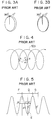
- a body to be examined P located on a bed plate 100 is moved along a direction of its body axis while an X-ray tube 101 and a detector 102 are rotated around the body to be examined P, such that the X-ray tube 101 moves along a helical trajectory 103 shown in Fig. 2 relative to the body to be examined P.
- tomographic image data are obtained from data collected during one rotation around the body to be examined P, such as those collected between points a and b shown in Fig, 2.
- Such a helical scan imaging has an advantage that the three-dimensional information on the body to be examined P can be obtained in a relatively short period of time.
- the slice plane obtained from data collected between the points a and b does not appears like a normal slice plane shown in Fig. 3A which can be obtained by the ordinary scans, but appears as shown in Fig, 3B in which 0° plane and 360° plane do not coincide with each other, so that when these data are directly used in reconstructing the image, the strong artefacts appear on the reconstructed image. For this reason, the reduction of the artefacts is achieved by deriving the data of the same single slice plane from the collected data by using the interpolation as follows.
- the data at a point C of a desired rotational phase on a desired slice plane can be obtained by using the interpolation of the data d A of the point A in the same rotational phase as that of the point C and on a part of the trajectory 103 neighboring the point C, and the data d B of the point B in the same rotational phase as that of the point C and on another part of the trajectory 103 neighboring the point C. Therefore, in a case of using a linear interpolation, the data d C at the point C can be obtained by the following expression: where 1 is a distance between the points A and C, and m is a distance between the points B and C, as shown in Fig. 4.
- the data in order to obtain the necessary data for reconstructing the image at a slice center position E, the data must be collected at least at a main data region D which covers a half rotation (180°) ahead and a half rotation (180°) behind the slice center position E in a case of a full scan.
- the data for reconstruction are to be derived from the collected data by using the interpolation
- the data must also be collected at supplementary data regions F and G which cover a half rotation (180°) ahead and a half rotation (180°) behind the main data region D.
- the data at a point C' on the slice center position E by the interpolation the data at a point A' in the main data region D as well as the data at a point B' in the supplementary data region F become necessary.
- the operator must position the body to be examined P and the bed plate 100 and set up the scanning region such that the scan and the data collection can be carried out for the main data region D and possibly also for the supplementary data regions F and G if necessary, according to the desired imaging regions on the body to be examined P.
- the operator position the body to be examined P and the bed plate 100 and set up the scanning region such that the scan also covers the regions for the initial acceleration and the final deceleration of the motion of the bed plate 100 along the body axis of the body to be examined P at which the data collection is unnecessary, so as to obtain the accurate data collected only while the bed plate 100 is moving at a constant speed.
- an X-ray CT apparatus for carrying out a helical scan imaging, comprising: input means for entering a desired imaging region; a bed plate for carrying a body to be examined along a direction of the body axis of the body to be examined, which is linearly movable along the direction of the body axis of the body to be examined; an X-ray tube for irradiating X-rays on the body to be examined on the bed plate; a detector for detecting the X-rays irradiated by the X-ray tube and penetrated through the body to be examined, where the X-ray tube and the detector are integrally rotatable around the body to be examined at a predetermined constant angular speed; data collection means for collecting data concerning the X-rays detected by the detector according to the desired imaging region entered by the input means; image reconstruction means for reconstructing tomographic images according to the data collected by the data collection means; and bed plate control means for controlling a linear motion of the bed plate
- a method of a helical scan imaging in an X-ray CT comprising the steps of: placing a body to be examined on a bed plate which is linearly movable along a direction of a body axis of the body to be examined; entering a desired imaging region; integrally rotating an X-ray tube for irradiating X-rays on the body to be examined on the bed plate and a detector for detecting the X-rays irradiated by the X-ray tube and penetrated through the body to be examined, around the body to be examined at a predetermined constant angular speed; collecting data concerning the X-rays detected by the detector according to the desired imaging region entered at the entering step; reconstructing tomographic images according to the data collected at the collecting step; and automatically controlling a linear motion of the bed plate according to the desired imaging region entered at the entering step such that the bed plate is linearly moved through a distance covered by a scanning region appropriate for the collecting step to collect the data required by
- Fig. 1 is a front view of a main part of a conventional X-ray CT apparatus for carrying out a helical scan imaging.
- Fig. 2 is a perspective view of a body to be examined, showing a trajectory of an X-ray tube around the body to be examined realizing in the helical scan imaging.
- Fig. 3A is a perspective view of a typical slice plane obtained by an ordinary scanning in an X-ray CT apparatus.
- Fig. 3B is a perspective view of a typical slice plane obtained by the helical scan imaging in an X-ray CT apparatus.
- Fig. 4 is a perspective view of a trajectory of the X-ray tube realizing in the helical scan imaging, for explaining the linear interpolation for deriving the data for the image reconstruction.
- Fig. 5 is a side view of a trajectory of the X-ray tube realizing in the helical scan imaging, for explaining a main data region and supplementary data regions to be set up around a slice center position.
- Fig. 6 is a schematic block diagram of one embodiment of an X-ray CT apparatus according to the present invention.
- Fig. 7 is a side view of a body to be examined, showing one possible initial set up realizable in the apparatus of Fig. 6.
- Fig. 8 is a side view of a body to be examined, showing another possible initial set up realizable in the apparatus of Fig. 6.
- FIG. 6 one embodiment of an X-ray CT apparatus according to the present invention will be described in detail.
- an X-ray CT apparatus 1 has a scanner unit 2 for carrying out scans with respect to a body to be examined P, including a bed plate 3 for carrying the body to be examined P along a direction of the body axis of the body to be examined P, an X-ray tube 4 for irradiating X-rays on the body to be examined P on the bed plate 3, and a detector 5 for detecting the X-rays irradiated by the X-ray tube 4 and penetrated through the body to be examined P, where the bed plate 3 is linearly movable along the direction of the body axis of the body to be examined P, while the X-ray tube 4 and the detector 5 are integrally rotatable around the body to be examined P at a predetermined constant angular speed.
- the helical scan imaging is carried out by moving the body to be examined P located on the bed plate 3 along the direction of the body axis of the body to be examined P while rotating the X-ray tube 4 and the detector 5 around the body to be examined P, such that the X-ray tube 4 moves along a helical trajectory relative to the body to be examined P.
- this X-ray CT apparatus 1 further comprises a bed plate driving unit 6 for driving the bed plate 3 into the linear motion along the direction of the body axis of the body to be examined P; a bed plate controller 7 for controlling the driving operation by the bed plate driving unit 6 in order to control the linear motion of the bed plate 3 appropriately; a data collection unit 8 for collecting data concerning the X-rays detected by the detector 5; an image reconstruction unit 9 for reconstructing the tomographic images according to the data collected by the data collection unit 8; a display unit 10 for displaying the tomographic images reconstructed by the image reconstruction unit 9; a data collection controller 11 for controlling the data collection operation of the data collection unit 8 appropriately; and the input unit 12 from which an operator enters a desired scanning region, according to which the bed plate controller 7 and the data collection controller 11 control the bed plate driving unit 6 and the data collection unit 8.
- the operator In carrying out the helical scan imaging in this X-ray CT apparatus, the operator enters the desired imaging region in which the tomographic images are to be obtained for the slice planes located therein, through the input unit 12, and places the body to be examined P on the bed plate 3 such that a scan start side end of the imaging region is located at a predetermined scanning position.
- the bed plate controller 7 and the data collection controller 11 controls the bed plate driving unit 6 and the data collection unit 8 as follows.
- the bed plate controller 7 automatically determines extra data regions L and R each of which includes a half main data region covering a half rotation (180°) part of a main data region for a first slice plane in the imaging region J and an associated supplementary data region covering additional half rotation (180°) adjacent to the half main data region, as well as an initial acceleration region M for accounting an initial acceleration of the bed plate 3 and a final deceleration region S for accounting a final deceleration of the bed plate 3, and controls the bed plate driving unit 6 to move the bed plate 3 in a direction opposite to a scanning direction for such a distance that a scan start side end N of the initial acceleration region M is moved to the scanning position.
- the extra data regions L and R and the initial acceleration region M and the final deceleration region S can be determined in advance according to the predetermined constant rotational speed of the X-ray tube 4 and the detector 5 and a linear motion characteristic of the bed plate 3.
- the X-ray tube 4 and the detector 5 are integrally rotated at a predetermined constant angular speed around the body to be examined P at the scanning position while the bed plate controller 7 controls the bed plate driving unit 6 to move the bed plate 3 in the scanning direction such that the scanning is carried out for the entire scanning region formed by the imaging region J, extra data regions L and R, initial acceleration region M and final deceleration region S until a scan finish side end T of the final deceleration region S stops at the scanning position.
- the bed plate 3 initially accelerates for a distance covered by the initial acceleration region M, moves at a predetermined constant linear speed through a distance covered by the extra data regions L and R and the imaging region J, and finally decelerates for a distance covered by the final deceleration region S, such that the X-ray tube 4 moves along a helical trajectory relative to the body to be examined P.
- the data collection controller 11 when the imaging region J is set up with respect to the body to be examined P with a scan start side end K located at the scanning position, the data collection controller 11 also similarly determines extra data regions L and R as well as the initial acceleration and the final deceleration region S around the imaging region J automatically, and controls the data collection unit 8 such that the data concerning the X-rays detected by the detector 5 are collected only in the extra data regions L and R and the imaging region J. In other words, the data are collected by the data collection unit 8 between a scan start side end U of the extra data region L and a scan finish side end W of the extra data region R.
- the data collected by the data collection unit 8 from the extra data regions L and R and the imaging region J are fed to the image reconstruction unit 9 in which image data necessary to reconstruct the tomographic images at desired slice planes are derived by using the interpolation on the collected data, and the tomographic images at the desired slice planes are reconstructed by using the derived image data.
- the interpolation can be achieved similarly to a conventional manner described above in the background of the invention section.
- the reconstructed tomographic images are then displayed on the display unit 10.
- the initial set up operation for the helical scan imaging can be achieved by simply specifying the desired imaging region J at the input unit 12, so that the scanning region can be set up accurately, while reducing the burden of the operator.
- the bed plate controller 7 may controls the bed plate driving unit 6 as follows.
- the bed plate controller 7 determines a readjustment region Y containing another extra data region adjacent to the position X, correction data region, and another initial acceleration region, and controls the bed plate driving unit 6 to move the bed plate 3 in a direction opposite to a scanning direction for such a distance that a scan start side end Z of the readjustment region Y is moved to the scanning position, such that the next scan can be started at the scan start side end Z of the readjustment region Y.
- the correction data region is provided in the readjustment region Y in order to obtain additional data necessary in removing the inconsistency in the collected data due to the displacement of the slice plane caused by the physical motion of the body to be examined P during the readjustment between the successive scans.
- the data collected at the additional extra region and the correction data region overlap with the data collected in the previous scan, so as to enable the effective data correction for the subsequent scan.
- the readjustment may be achieved such that the data collected at a part of the main data region in the subsequent scan also overlap with the data collected in the previous scan, in order to account for the physical motion of the target portion of the body to be examined P due to breathing or some other cause occurring during the readjustment between the successive scans.
- any one of the initial acceleration region M, final deceleration region S, and a supplementary data region in the the extra data regions L and R may be omitted if its omission is preferred.
- the present invention is also equally applicable to an X-ray CT apparatus for carrying out a half scan in which the data for one rotation are obtained by using scans of 90° plus a fan angle on both sides of the desired image center position.
Abstract
Description
- The present invention relates to an X-ray computed tomography (CT), and more particularly to a so called helical scan imaging in which a body to be examined is moved along its body axis during the scanning operation in such an X-ray CT.
- Recently, there has been a proposition of an X-ray CT apparatus capable of carrying out a so called helical scan imaging. As shown in Fig. 1, in the helical scan imaging, a body to be examined P located on a
bed plate 100 is moved along a direction of its body axis while anX-ray tube 101 and adetector 102 are rotated around the body to be examined P, such that theX-ray tube 101 moves along ahelical trajectory 103 shown in Fig. 2 relative to the body to be examined P. In reconstructing the image from the data collected by such a helical scan, tomographic image data are obtained from data collected during one rotation around the body to be examined P, such as those collected between points a and b shown in Fig, 2. Such a helical scan imaging has an advantage that the three-dimensional information on the body to be examined P can be obtained in a relatively short period of time. - Now, in such a helical scan imaging, the slice plane obtained from data collected between the points a and b does not appears like a normal slice plane shown in Fig. 3A which can be obtained by the ordinary scans, but appears as shown in Fig, 3B in which 0° plane and 360° plane do not coincide with each other, so that when these data are directly used in reconstructing the image, the strong artefacts appear on the reconstructed image. For this reason, the reduction of the artefacts is achieved by deriving the data of the same single slice plane from the collected data by using the interpolation as follows.
- For example, as shown in Fig. 4, the data at a point C of a desired rotational phase on a desired slice plane can be obtained by using the interpolation of the data dA of the point A in the same rotational phase as that of the point C and on a part of the
trajectory 103 neighboring the point C, and the data dB of the point B in the same rotational phase as that of the point C and on another part of thetrajectory 103 neighboring the point C. Therefore, in a case of using a linear interpolation, the data dC at the point C can be obtained by the following expression:
where 1 is a distance between the points A and C, and m is a distance between the points B and C, as shown in Fig. 4. - Now, as shown in Fig. 8, in reconstructing the image from the data collected by the helical scan, in order to obtain the necessary data for reconstructing the image at a slice center position E, the data must be collected at least at a main data region D which covers a half rotation (180°) ahead and a half rotation (180°) behind the slice center position E in a case of a full scan.
- In addition, in a case the data for reconstruction are to be derived from the collected data by using the interpolation, the data must also be collected at supplementary data regions F and G which cover a half rotation (180°) ahead and a half rotation (180°) behind the main data region D. Namely, in order to obtain the data at a point C' on the slice center position E by the interpolation, the data at a point A' in the main data region D as well as the data at a point B' in the supplementary data region F become necessary. Namely, in order to obtain the data at a point C'' on the slice center position E by the interpolation, the data at a point A'' in the main data region D as well as the data at a point B'' in the supplementary data region G become necessary.
- Therefore, the operator must position the body to be examined P and the
bed plate 100 and set up the scanning region such that the scan and the data collection can be carried out for the main data region D and possibly also for the supplementary data regions F and G if necessary, according to the desired imaging regions on the body to be examined P. - Moreover, it is further preferable for the operator to position the body to be examined P and the
bed plate 100 and set up the scanning region such that the scan also covers the regions for the initial acceleration and the final deceleration of the motion of thebed plate 100 along the body axis of the body to be examined P at which the data collection is unnecessary, so as to obtain the accurate data collected only while thebed plate 100 is moving at a constant speed. - However, in a conventional X-ray CT apparatus capable of carrying out the helical scan imaging, the operator must carry out the initial set up operation including the positioning of the body to be examined P and the
bed plate 100 and setting up of the scanning region described above, on his own discretion, so that the these positioning and setting up operations have been cumbersome as well as not very accurate. - It is therefore an object of the present invention to provide a method and an apparatus for a helical scan imaging in an X-ray CT, in which the initial set up operation can be achieved easily and accurately, without relying heavily on the discretion of the operator.
- According to one aspect of the present invention there is provided an X-ray CT apparatus for carrying out a helical scan imaging, comprising: input means for entering a desired imaging region; a bed plate for carrying a body to be examined along a direction of the body axis of the body to be examined, which is linearly movable along the direction of the body axis of the body to be examined; an X-ray tube for irradiating X-rays on the body to be examined on the bed plate; a detector for detecting the X-rays irradiated by the X-ray tube and penetrated through the body to be examined, where the X-ray tube and the detector are integrally rotatable around the body to be examined at a predetermined constant angular speed; data collection means for collecting data concerning the X-rays detected by the detector according to the desired imaging region entered by the input means; image reconstruction means for reconstructing tomographic images according to the data collected by the data collection means; and bed plate control means for controlling a linear motion of the bed plate according to the desired imaging region entered by the input means such that the bed plate is linearly moved through a distance covered by a scanning region appropriate for the data collection means to collect the data required by the image reconstruction means to reconstruct the tomographic images for the desired imaging region.
- According to another aspect of the present invention there is provided a method of a helical scan imaging in an X-ray CT, comprising the steps of: placing a body to be examined on a bed plate which is linearly movable along a direction of a body axis of the body to be examined; entering a desired imaging region; integrally rotating an X-ray tube for irradiating X-rays on the body to be examined on the bed plate and a detector for detecting the X-rays irradiated by the X-ray tube and penetrated through the body to be examined, around the body to be examined at a predetermined constant angular speed; collecting data concerning the X-rays detected by the detector according to the desired imaging region entered at the entering step; reconstructing tomographic images according to the data collected at the collecting step; and automatically controlling a linear motion of the bed plate according to the desired imaging region entered at the entering step such that the bed plate is linearly moved through a distance covered by a scanning region appropriate for the collecting step to collect the data required by the reconstructing step to reconstruct the tomographic images for the desired imaging region.
- Other features and advantages of the present invention will become apparent from the following description taken in conjunction with the accompanying drawings.
- Fig. 1 is a front view of a main part of a conventional X-ray CT apparatus for carrying out a helical scan imaging.
- Fig. 2 is a perspective view of a body to be examined, showing a trajectory of an X-ray tube around the body to be examined realizing in the helical scan imaging.
- Fig. 3A is a perspective view of a typical slice plane obtained by an ordinary scanning in an X-ray CT apparatus.
- Fig. 3B is a perspective view of a typical slice plane obtained by the helical scan imaging in an X-ray CT apparatus.
- Fig. 4 is a perspective view of a trajectory of the X-ray tube realizing in the helical scan imaging, for explaining the linear interpolation for deriving the data for the image reconstruction.
- Fig. 5 is a side view of a trajectory of the X-ray tube realizing in the helical scan imaging, for explaining a main data region and supplementary data regions to be set up around a slice center position.
- Fig. 6 is a schematic block diagram of one embodiment of an X-ray CT apparatus according to the present invention.
- Fig. 7 is a side view of a body to be examined, showing one possible initial set up realizable in the apparatus of Fig. 6.
- Fig. 8 is a side view of a body to be examined, showing another possible initial set up realizable in the apparatus of Fig. 6.
- Referring now to Fig. 6, one embodiment of an X-ray CT apparatus according to the present invention will be described in detail.
- In this embodiment, an
X-ray CT apparatus 1 has ascanner unit 2 for carrying out scans with respect to a body to be examined P, including abed plate 3 for carrying the body to be examined P along a direction of the body axis of the body to be examined P, anX-ray tube 4 for irradiating X-rays on the body to be examined P on thebed plate 3, and adetector 5 for detecting the X-rays irradiated by theX-ray tube 4 and penetrated through the body to be examined P, where thebed plate 3 is linearly movable along the direction of the body axis of the body to be examined P, while theX-ray tube 4 and thedetector 5 are integrally rotatable around the body to be examined P at a predetermined constant angular speed. In thisscanner unit 2, the helical scan imaging is carried out by moving the body to be examined P located on thebed plate 3 along the direction of the body axis of the body to be examined P while rotating theX-ray tube 4 and thedetector 5 around the body to be examined P, such that theX-ray tube 4 moves along a helical trajectory relative to the body to be examined P. - In addition, this X-ray
CT apparatus 1 further comprises a bedplate driving unit 6 for driving thebed plate 3 into the linear motion along the direction of the body axis of the body to be examined P; abed plate controller 7 for controlling the driving operation by the bedplate driving unit 6 in order to control the linear motion of thebed plate 3 appropriately; adata collection unit 8 for collecting data concerning the X-rays detected by thedetector 5; animage reconstruction unit 9 for reconstructing the tomographic images according to the data collected by thedata collection unit 8; adisplay unit 10 for displaying the tomographic images reconstructed by theimage reconstruction unit 9; adata collection controller 11 for controlling the data collection operation of thedata collection unit 8 appropriately; and theinput unit 12 from which an operator enters a desired scanning region, according to which thebed plate controller 7 and thedata collection controller 11 control the bedplate driving unit 6 and thedata collection unit 8. - In carrying out the helical scan imaging in this X-ray CT apparatus, the operator enters the desired imaging region in which the tomographic images are to be obtained for the slice planes located therein, through the
input unit 12, and places the body to be examined P on thebed plate 3 such that a scan start side end of the imaging region is located at a predetermined scanning position. - Then, in accordance with the desired imaging region entered at the
input unit 12, thebed plate controller 7 and thedata collection controller 11 controls the bedplate driving unit 6 and thedata collection unit 8 as follows. - Namely, as shown in Fig. 7, when the imaging region J is set up with respect to the body to be examined P with a scan start side end K located at the scanning position, the
bed plate controller 7 automatically determines extra data regions L and R each of which includes a half main data region covering a half rotation (180°) part of a main data region for a first slice plane in the imaging region J and an associated supplementary data region covering additional half rotation (180°) adjacent to the half main data region, as well as an initial acceleration region M for accounting an initial acceleration of thebed plate 3 and a final deceleration region S for accounting a final deceleration of thebed plate 3, and controls the bedplate driving unit 6 to move thebed plate 3 in a direction opposite to a scanning direction for such a distance that a scan start side end N of the initial acceleration region M is moved to the scanning position. - Here, the extra data regions L and R and the initial acceleration region M and the final deceleration region S can be determined in advance according to the predetermined constant rotational speed of the
X-ray tube 4 and thedetector 5 and a linear motion characteristic of thebed plate 3. - Then, as the helical scan imaging starts, the
X-ray tube 4 and thedetector 5 are integrally rotated at a predetermined constant angular speed around the body to be examined P at the scanning position while thebed plate controller 7 controls the bedplate driving unit 6 to move thebed plate 3 in the scanning direction such that the scanning is carried out for the entire scanning region formed by the imaging region J, extra data regions L and R, initial acceleration region M and final deceleration region S until a scan finish side end T of the final deceleration region S stops at the scanning position. - As a result, the
bed plate 3 initially accelerates for a distance covered by the initial acceleration region M, moves at a predetermined constant linear speed through a distance covered by the extra data regions L and R and the imaging region J, and finally decelerates for a distance covered by the final deceleration region S, such that theX-ray tube 4 moves along a helical trajectory relative to the body to be examined P. - Meanwhile, when the imaging region J is set up with respect to the body to be examined P with a scan start side end K located at the scanning position, the
data collection controller 11 also similarly determines extra data regions L and R as well as the initial acceleration and the final deceleration region S around the imaging region J automatically, and controls thedata collection unit 8 such that the data concerning the X-rays detected by thedetector 5 are collected only in the extra data regions L and R and the imaging region J. In other words, the data are collected by thedata collection unit 8 between a scan start side end U of the extra data region L and a scan finish side end W of the extra data region R. - Then, the data collected by the
data collection unit 8 from the extra data regions L and R and the imaging region J are fed to theimage reconstruction unit 9 in which image data necessary to reconstruct the tomographic images at desired slice planes are derived by using the interpolation on the collected data, and the tomographic images at the desired slice planes are reconstructed by using the derived image data. Here, the interpolation can be achieved similarly to a conventional manner described above in the background of the invention section. The reconstructed tomographic images are then displayed on thedisplay unit 10. - Thus, according to this embodiment, the initial set up operation for the helical scan imaging can be achieved by simply specifying the desired imaging region J at the
input unit 12, so that the scanning region can be set up accurately, while reducing the burden of the operator. - It is to be noted that in a case the imaging region J is too wide to be covered by a single scan such that more than one scans are required, the
bed plate controller 7 may controls the bedplate driving unit 6 as follows. - Namely, in such a case, as shown in Fig. 8, when the first scan finishes at a position X, the
bed plate controller 7 determines a readjustment region Y containing another extra data region adjacent to the position X, correction data region, and another initial acceleration region, and controls the bedplate driving unit 6 to move thebed plate 3 in a direction opposite to a scanning direction for such a distance that a scan start side end Z of the readjustment region Y is moved to the scanning position, such that the next scan can be started at the scan start side end Z of the readjustment region Y. - Here, the correction data region is provided in the readjustment region Y in order to obtain additional data necessary in removing the inconsistency in the collected data due to the displacement of the slice plane caused by the physical motion of the body to be examined P during the readjustment between the successive scans. Thus, in this case, the data collected at the additional extra region and the correction data region overlap with the data collected in the previous scan, so as to enable the effective data correction for the subsequent scan. Furthermore, the readjustment may be achieved such that the data collected at a part of the main data region in the subsequent scan also overlap with the data collected in the previous scan, in order to account for the physical motion of the target portion of the body to be examined P due to breathing or some other cause occurring during the readjustment between the successive scans.
- It is also to be noted that, in the above embodiment, any one of the initial acceleration region M, final deceleration region S, and a supplementary data region in the the extra data regions L and R may be omitted if its omission is preferred.
- Moreover, although the above embodiment has been described for a third generation type X-ray CT apparatus, the present invention is equally applicable to a fourth generation type X-ray CT apparatus.
- Similarly, although the above embodiment has been described for a case of a full scan using a full 360° rotation of the X-ray tube and the detector around the body to be examined, the present invention is also equally applicable to an X-ray CT apparatus for carrying out a half scan in which the data for one rotation are obtained by using scans of 90° plus a fan angle on both sides of the desired image center position.
- Besides these, many modifications and variations of the above embodiment may be made without departing from the novel and advantageous features of the present invention. Accordingly, all such modifications and variations are intended to be included within the scope of the appended claims.
Claims (24)
- An X-ray CT apparatus for carrying out a helical scan imaging, comprising:
input means for entering a desired imaging region;
a bed plate for carrying a body to be examined along a direction of the body axis of the body to be examined, which is linearly movable along the direction of the body axis of the body to be examined;
an X-ray tube for irradiating X-rays on the body to be examined on the bed plate;
a detector for detecting the X-rays irradiated by the X-ray tube and penetrated through the body to be examined, where the X-ray tube and the detector are integrally rotatable around the body to be examined at a predetermined constant angular speed;
data collection means for collecting data concerning the X-rays detected by the detector according to the desired imaging region entered by the input means;
image reconstruction means for reconstructing tomographic images according to the data collected by the data collection means; and
bed plate control means for controlling a linear motion of the bed plate according to the desired imaging region entered by the input means such that the bed plate is linearly moved through a distance covered by a scanning region appropriate for the data collection means to collect the data required by the image reconstruction means to reconstruct the tomographic images for the desired imaging region. - The X-ray CT apparatus of claim 1, wherein the scanning region includes half main data regions, each of which is covering a half rotation (180°) part of a main data region for each of slice planes located at ends of the desired imaging region.
- The X-ray CT apparatus of claim 2, wherein the data collection means collects the data from the desired imaging region and the half main data regions.
- The X-ray CT apparatus of claim 2, wherein the scanning region further includes supplementary data regions, each of which is covering a half rotation (180°) adjacent to each of the half main data regions.
- The X-ray CT apparatus of claim 4, wherein the data collection means also collects the data from the supplementary data regions, where the data collected from the supplementary data regions are utilized in carrying out interpolations for deriving data in the desired imaging region.
- The X-ray CT apparatus of any of claims to 5 1, wherein the scanning region includes an initial acceleration region for accounting an initial acceleration of the bed plate.
- The X-ray CT apparatus of any of claims 1 to 6, wherein the scanning region includes an final deceleration region for accounting a final deceleration of the bed plate.
- The X-ray CT apparatus of any of claims 1 to 7, wherein the scanning region is determined in advance according to the predetermined constant rotational speed of the X-ray tube and the detector and a linear motion characteristic of the bed plate.
- The X-ray CT apparatus of any of claims 1 to 8, wherein the bed plate moves the distance covered by the scanning region in a plurality of scans, and the bed plate control means controls the linear motion of the bed plate such that each scan by the bed plate includes a readjustment region which is overlapping with a region covered by a previous scan.
- The X-ray CT apparatus of claim 9, wherein the readjustment region includes a correction data region from which additional data necessary in removing inconsistency in the data collected by the data collection means introduced by a readjustment between the successive scans are collected by the data collection means.
- The X-ray CT apparatus of any of claims 1 to 10, wherein the X-ray tube and the detector carry out a full scan using a full 360° rotation around the body to be examined.
- The X-ray CT apparatus of any of claims 1 to 10, wherein the X-ray tube and the detector carry out a half scan using 90° plus a fan angle scans around the body to be examined.
- A method of a helical scan imaging in an X-ray CT, comprising the steps of:
placing a body to be examined on a bed plate which is linearly movable along a direction of a body axis of the body to be examined;
entering a desired imaging region;
integrally rotating an X-ray tube for irradiating X-rays on the body to be examined on the bed plate and a detector for detecting the X-rays irradiated by the X-ray tube and penetrated through the body to be examined, around the body to be examined at a predetermined constant angular speed;
collecting data concerning the X-rays detected by the detector according to the desired imaging region entered at the entering step;
reconstructing tomographic images according to the data collected at the collecting step; and
automatically controlling a linear motion of the bed plate according to the desired imaging region entered at the entering step such that the bed plate is linearly moved through a distance covered by a scanning region appropriate for the collecting step to collect the data required by the reconstructing step to reconstruct the tomographic images for the desired imaging region. - The method of claim 13, wherein the scanning region includes half main data regions, each of which is covering a half rotation (180°) part of a main data region for each of slice planes located at ends of the desired imaging region.
- The method of claim 14, wherein at the collecting step, the data from the desired imaging region and the half main data regions are collected.
- The method of claim 14, wherein the scanning region further includes supplementary data regions, each of which is covering a half rotation (180°) adjacent to each of the half main data regions.
- The method of claim 16, wherein the collecting step, the data from the supplementary data regions are also collected, where the data collected from the supplementary data regions are utilized in carrying out interpolations for deriving data in the desired imaging region.
- The method of any of claims 13 to 17, wherein the scanning region includes an initial acceleration region for accounting an initial acceleration of the bed plate.
- The method of any of claims 13 to 18, wherein the scanning region includes an final deceleration region for accounting a final deceleration of the bed plate.
- The method of any of claims 13 to 19, wherein the scanning region is determined in advance according to the predetermined constant rotational speed of the X-ray tube and the detector and a linear motion characteristic of the bed plate.
- The method of any of claims 13 to 20, wherein the bed plate moves the distance covered by the scanning region in a plurality of scans, and at the controlling step, the linear motion of the bed plate is controlled such that each scan by the bed plate includes a readjustment region which is overlapping with a region covered by a previous scan.
- The method of claim 21, wherein the readjustment region includes a correction data region from which additional data necessary in removing inconsistency in the data collected at the collecting step introduced by a readjustment between the successive scans are collected at collecting step.
- The method of any of claims 13 to 22, wherein the X-ray tube and the detector carry out a full scan using a full 360° rotation around the body to be examined.
- The method of any of claims 13 to 22, wherein the X-ray tube and the detector carry out a half scan using 90° plus a fan angle scans around the body to be examined.
Priority Applications (1)
| Application Number | Priority Date | Filing Date | Title |
|---|---|---|---|
| EP95113262A EP0691104B1 (en) | 1990-11-01 | 1991-10-28 | Apparatus for helical scan imaging in X-ray computed tomography |
Applications Claiming Priority (2)
| Application Number | Priority Date | Filing Date | Title |
|---|---|---|---|
| JP2293595A JP2607749B2 (en) | 1990-11-01 | 1990-11-01 | X-ray CT system |
| JP293595/90 | 1990-11-01 |
Related Child Applications (1)
| Application Number | Title | Priority Date | Filing Date |
|---|---|---|---|
| EP95113262.0 Division-Into | 1991-10-28 |
Publications (2)
| Publication Number | Publication Date |
|---|---|
| EP0483729A1 true EP0483729A1 (en) | 1992-05-06 |
| EP0483729B1 EP0483729B1 (en) | 1996-05-15 |
Family
ID=17796755
Family Applications (2)
| Application Number | Title | Priority Date | Filing Date |
|---|---|---|---|
| EP95113262A Expired - Lifetime EP0691104B1 (en) | 1990-11-01 | 1991-10-28 | Apparatus for helical scan imaging in X-ray computed tomography |
| EP91118359A Expired - Lifetime EP0483729B1 (en) | 1990-11-01 | 1991-10-28 | Method and apparatus for helical scan imaging in X-ray computed tomography |
Family Applications Before (1)
| Application Number | Title | Priority Date | Filing Date |
|---|---|---|---|
| EP95113262A Expired - Lifetime EP0691104B1 (en) | 1990-11-01 | 1991-10-28 | Apparatus for helical scan imaging in X-ray computed tomography |
Country Status (4)
| Country | Link |
|---|---|
| US (3) | US5224135A (en) |
| EP (2) | EP0691104B1 (en) |
| JP (1) | JP2607749B2 (en) |
| DE (2) | DE69119537T2 (en) |
Cited By (5)
| Publication number | Priority date | Publication date | Assignee | Title |
|---|---|---|---|---|
| DE4137031C1 (en) * | 1991-11-11 | 1993-04-08 | Siemens Ag, 8000 Muenchen, De | Computer tomograph equipment providing three=dimensional scanning - relatively rotates measuring unit, consisting of X=ray radiator and radiation detector, and patient couch |
| CN102753993A (en) * | 2011-01-20 | 2012-10-24 | 株式会社东芝 | Positron emission computed tomography device, method executed by positron emission computed tomography device, and program |
| CN107296609A (en) * | 2017-06-16 | 2017-10-27 | 上海联影医疗科技有限公司 | A kind of medical image scan localization method, system and computer-readable recording medium |
| CN109567843A (en) * | 2019-02-02 | 2019-04-05 | 上海联影医疗科技有限公司 | A kind of image scanning automatic positioning method, device, equipment and medium |
| CN110327069A (en) * | 2019-07-01 | 2019-10-15 | 赛诺威盛科技(北京)有限公司 | A method of reducing CT helical scanning range |
Families Citing this family (24)
| Publication number | Priority date | Publication date | Assignee | Title |
|---|---|---|---|---|
| JP2607749B2 (en) * | 1990-11-01 | 1997-05-07 | 株式会社東芝 | X-ray CT system |
| JP3047928B2 (en) * | 1991-03-18 | 2000-06-05 | 株式会社日立メディコ | X-ray CT system |
| JPH06205770A (en) * | 1993-01-11 | 1994-07-26 | Hitachi Medical Corp | X-ray ct system |
| DE4321080C1 (en) * | 1993-06-24 | 1994-12-08 | Siemens Ag | Computer tomograph with helical scanning |
| US5448607A (en) * | 1994-02-08 | 1995-09-05 | Analogic Corporation | X-ray tomography system with gantry pivot and translation control |
| US5409151A (en) * | 1994-07-01 | 1995-04-25 | Freimark; Justin | Bottle assembly for carrying liquids |
| JP3583503B2 (en) * | 1995-04-13 | 2004-11-04 | 株式会社日立メディコ | Medical diagnostic CT equipment |
| US5805288A (en) * | 1996-03-05 | 1998-09-08 | Laserscore, Inc. | Apparatus for detecting the presence and location of at least one object in a field |
| US5682413A (en) * | 1996-06-21 | 1997-10-28 | Picker International, Inc. | Rotational angiography dye and mask image acquisition and synchronization |
| US5706325A (en) * | 1996-12-05 | 1998-01-06 | General Electric Company | Exact regional reconstruction of longitudinally-unbounded objects using a circle-and-line cone beam tomographic system |
| CA2319535A1 (en) * | 1998-02-04 | 1999-08-12 | Laserscore, Inc. | System for detecting the presence and location of at least one object in a field by using a divergent radiation source and an array of opposed plural detectors which rotate together around the field |
| US6363134B1 (en) * | 1999-01-13 | 2002-03-26 | Kabushiki Kaisha Toshiba | X-ray computed tomography apparatus |
| US6816567B2 (en) * | 2002-07-15 | 2004-11-09 | Ge Medical System Global Technology Company, Llc | System and method for acquiring x-ray data |
| JP2005040582A (en) * | 2003-07-07 | 2005-02-17 | Ge Medical Systems Global Technology Co Llc | X-ray ct imaging method and x-ray ct apparatus |
| JP4634770B2 (en) * | 2004-10-06 | 2011-02-16 | 株式会社東芝 | X-ray CT apparatus and image reconstruction method |
| JP4322894B2 (en) * | 2006-06-20 | 2009-09-02 | ジーイー・メディカル・システムズ・グローバル・テクノロジー・カンパニー・エルエルシー | X-ray CT system |
| CN101516268B (en) * | 2006-09-29 | 2011-11-16 | 皇家飞利浦电子股份有限公司 | Fly-by scanning |
| US7869559B2 (en) * | 2006-10-19 | 2011-01-11 | General Electric Company | X-ray detector methods and apparatus |
| US8822409B2 (en) * | 2007-06-20 | 2014-09-02 | Phylogica Limited | Compositions and uses thereof for the treatment of acute respiratory distress syndrome (ARDS) and clinical disorders associated with therewith |
| JP5340748B2 (en) * | 2009-01-05 | 2013-11-13 | ジーイー・メディカル・システムズ・グローバル・テクノロジー・カンパニー・エルエルシー | X-ray CT system |
| US9084542B2 (en) | 2009-11-10 | 2015-07-21 | General Electric Company | Apparatus and methods for computed tomography imaging |
| JP6309250B2 (en) * | 2012-11-14 | 2018-04-11 | キヤノンメディカルシステムズ株式会社 | X-ray CT apparatus, control program for X-ray CT apparatus |
| JP2014166346A (en) * | 2013-01-31 | 2014-09-11 | Toshiba Corp | X-ray ct apparatus and program therefor |
| CN109171775A (en) * | 2018-07-04 | 2019-01-11 | 沈阳东软医疗系统有限公司 | Imaging method and scan control method, device, system, equipment and storage medium |
Citations (4)
| Publication number | Priority date | Publication date | Assignee | Title |
|---|---|---|---|---|
| EP0113879A2 (en) * | 1982-12-16 | 1984-07-25 | Kabushiki Kaisha Toshiba | Computerized tomographic apparatus utilizing a radiation source |
| US4789929A (en) * | 1987-05-14 | 1988-12-06 | Hitachi Medical Corporation | CT system for spirally scanning subject on a movable bed synchronized to X-ray tube revolution |
| EP0383232A2 (en) * | 1989-02-13 | 1990-08-22 | Kabushiki Kaisha Toshiba | Computerized tomographic apparatus |
| EP0450152A1 (en) * | 1990-04-04 | 1991-10-09 | Kabushiki Kaisha Toshiba | Computerized tomographic imaging method and apparatus utilizing data interpolation for helical scanning |
Family Cites Families (5)
| Publication number | Priority date | Publication date | Assignee | Title |
|---|---|---|---|---|
| JPH0767445B2 (en) * | 1985-10-14 | 1995-07-26 | 株式会社日立メディコ | X-ray CT system |
| JPS62139630A (en) * | 1985-12-16 | 1987-06-23 | 株式会社日立メディコ | X-ray ct apparatus |
| US5046003A (en) * | 1989-06-26 | 1991-09-03 | General Electric Company | Method for reducing skew image artifacts in helical projection imaging |
| JPH0787835B2 (en) * | 1990-06-27 | 1995-09-27 | 株式会社東芝 | X-ray tomography system |
| JP2607749B2 (en) * | 1990-11-01 | 1997-05-07 | 株式会社東芝 | X-ray CT system |
-
1990
- 1990-11-01 JP JP2293595A patent/JP2607749B2/en not_active Expired - Lifetime
-
1991
- 1991-10-28 DE DE69119537T patent/DE69119537T2/en not_active Expired - Lifetime
- 1991-10-28 EP EP95113262A patent/EP0691104B1/en not_active Expired - Lifetime
- 1991-10-28 EP EP91118359A patent/EP0483729B1/en not_active Expired - Lifetime
- 1991-10-28 DE DE69133051T patent/DE69133051T2/en not_active Expired - Lifetime
- 1991-10-30 US US07/784,223 patent/US5224135A/en not_active Expired - Lifetime
-
1993
- 1993-05-24 US US08/064,936 patent/US5386452A/en not_active Expired - Lifetime
-
1995
- 1995-01-12 US US08/371,789 patent/US5499283A/en not_active Expired - Lifetime
Patent Citations (4)
| Publication number | Priority date | Publication date | Assignee | Title |
|---|---|---|---|---|
| EP0113879A2 (en) * | 1982-12-16 | 1984-07-25 | Kabushiki Kaisha Toshiba | Computerized tomographic apparatus utilizing a radiation source |
| US4789929A (en) * | 1987-05-14 | 1988-12-06 | Hitachi Medical Corporation | CT system for spirally scanning subject on a movable bed synchronized to X-ray tube revolution |
| EP0383232A2 (en) * | 1989-02-13 | 1990-08-22 | Kabushiki Kaisha Toshiba | Computerized tomographic apparatus |
| EP0450152A1 (en) * | 1990-04-04 | 1991-10-09 | Kabushiki Kaisha Toshiba | Computerized tomographic imaging method and apparatus utilizing data interpolation for helical scanning |
Cited By (9)
| Publication number | Priority date | Publication date | Assignee | Title |
|---|---|---|---|---|
| DE4137031C1 (en) * | 1991-11-11 | 1993-04-08 | Siemens Ag, 8000 Muenchen, De | Computer tomograph equipment providing three=dimensional scanning - relatively rotates measuring unit, consisting of X=ray radiator and radiation detector, and patient couch |
| US5345381A (en) * | 1991-11-11 | 1994-09-06 | Siemens Aktiengesellschaft | Spiral scan computer tomography apparatus |
| CN102753993A (en) * | 2011-01-20 | 2012-10-24 | 株式会社东芝 | Positron emission computed tomography device, method executed by positron emission computed tomography device, and program |
| CN102753993B (en) * | 2011-01-20 | 2015-04-22 | 株式会社东芝 | Positron emission computed tomography device, method executed by positron emission computed tomography device, and program |
| CN107296609A (en) * | 2017-06-16 | 2017-10-27 | 上海联影医疗科技有限公司 | A kind of medical image scan localization method, system and computer-readable recording medium |
| CN107296609B (en) * | 2017-06-16 | 2021-06-01 | 上海联影医疗科技股份有限公司 | Medical imaging scanning positioning method, system and computer readable storage medium |
| US11246556B2 (en) | 2017-06-16 | 2022-02-15 | Shanghai United Imaging Healthcare Co., Ltd. | Systems and methods for medical image scanning positioning |
| CN109567843A (en) * | 2019-02-02 | 2019-04-05 | 上海联影医疗科技有限公司 | A kind of image scanning automatic positioning method, device, equipment and medium |
| CN110327069A (en) * | 2019-07-01 | 2019-10-15 | 赛诺威盛科技(北京)有限公司 | A method of reducing CT helical scanning range |
Also Published As
| Publication number | Publication date |
|---|---|
| US5386452A (en) | 1995-01-31 |
| JPH04170941A (en) | 1992-06-18 |
| EP0691104A2 (en) | 1996-01-10 |
| DE69119537D1 (en) | 1996-06-20 |
| EP0691104B1 (en) | 2002-06-26 |
| EP0483729B1 (en) | 1996-05-15 |
| JP2607749B2 (en) | 1997-05-07 |
| US5224135A (en) | 1993-06-29 |
| DE69133051T2 (en) | 2003-02-06 |
| EP0691104A3 (en) | 1996-04-03 |
| DE69119537T2 (en) | 1997-01-16 |
| US5499283A (en) | 1996-03-12 |
| DE69133051D1 (en) | 2002-08-01 |
Similar Documents
| Publication | Publication Date | Title |
|---|---|---|
| US5224135A (en) | Method and apparatus for helical scan imaging in x-ray computed tomography | |
| US4674046A (en) | Method and apparatus for obtaining three dimensional tomographic images by interpolation of a plurality of projection slice data bind for obtaining projection data for a chosen slice | |
| US7508903B2 (en) | Collimator control method and X-ray CT apparatus | |
| EP0531993B1 (en) | X-ray computerized tomographic imaging method and imaging system capable of forming scanogram data from helically scanned data | |
| US5103469A (en) | X-ray CT scanner | |
| US4789929A (en) | CT system for spirally scanning subject on a movable bed synchronized to X-ray tube revolution | |
| EP1324699B1 (en) | Cardiac helical half scan reconstructions for multiple detector row ct | |
| US20030031290A1 (en) | X-ray computed tomographic imaging apparatus | |
| EP0485999B1 (en) | Method and apparatus for specifying slice planes in X-ray computed tomography | |
| CA2010136A1 (en) | Method for reducing skew image artifacts in helical projection imaging | |
| US5528644A (en) | X-ray CT scanner and method of collecting image data in the same | |
| US20080031407A1 (en) | X-ray ct apparatus | |
| JP3732568B2 (en) | X-ray computed tomography system | |
| IL116258A (en) | Image reconstruction apparatus and method for helical scanning | |
| JPH0767445B2 (en) | X-ray CT system | |
| JPH07148155A (en) | Computerized tomographic apparatus | |
| JP2823531B2 (en) | X-ray CT system | |
| JP3305759B2 (en) | CT device | |
| JP3298224B2 (en) | X-ray CT system | |
| JP2676576B2 (en) | X-ray CT system | |
| JP3394038B2 (en) | X-ray CT scanner | |
| JP2824011B2 (en) | X-ray CT system | |
| JPH0471540A (en) | X-ray ct device | |
| JPH0795977A (en) | X-ray ct apparatus | |
| JP2824042B2 (en) | X-ray CT system |
Legal Events
| Date | Code | Title | Description |
|---|---|---|---|
| PUAI | Public reference made under article 153(3) epc to a published international application that has entered the european phase |
Free format text: ORIGINAL CODE: 0009012 |
|
| 17P | Request for examination filed |
Effective date: 19911028 |
|
| AK | Designated contracting states |
Kind code of ref document: A1 Designated state(s): DE NL |
|
| 17Q | First examination report despatched |
Effective date: 19940707 |
|
| GRAH | Despatch of communication of intention to grant a patent |
Free format text: ORIGINAL CODE: EPIDOS IGRA |
|
| GRAA | (expected) grant |
Free format text: ORIGINAL CODE: 0009210 |
|
| AK | Designated contracting states |
Kind code of ref document: B1 Designated state(s): DE NL |
|
| RAP1 | Party data changed (applicant data changed or rights of an application transferred) |
Owner name: KABUSHIKI KAISHA TOSHIBA |
|
| XX | Miscellaneous (additional remarks) |
Free format text: TEILANMELDUNG 95113262.0 EINGEREICHT AM 23/08/95. |
|
| XX | Miscellaneous (additional remarks) | ||
| REF | Corresponds to: |
Ref document number: 69119537 Country of ref document: DE Date of ref document: 19960620 |
|
| PLBE | No opposition filed within time limit |
Free format text: ORIGINAL CODE: 0009261 |
|
| STAA | Information on the status of an ep patent application or granted ep patent |
Free format text: STATUS: NO OPPOSITION FILED WITHIN TIME LIMIT |
|
| 26N | No opposition filed | ||
| PGFP | Annual fee paid to national office [announced via postgrant information from national office to epo] |
Ref country code: NL Payment date: 20101009 Year of fee payment: 20 |
|
| PGFP | Annual fee paid to national office [announced via postgrant information from national office to epo] |
Ref country code: DE Payment date: 20101020 Year of fee payment: 20 |
|
| REG | Reference to a national code |
Ref country code: DE Ref legal event code: R071 Ref document number: 69119537 Country of ref document: DE |
|
| REG | Reference to a national code |
Ref country code: DE Ref legal event code: R071 Ref document number: 69119537 Country of ref document: DE |
|
| REG | Reference to a national code |
Ref country code: NL Ref legal event code: V4 Effective date: 20111028 |
|
| PG25 | Lapsed in a contracting state [announced via postgrant information from national office to epo] |
Ref country code: NL Free format text: LAPSE BECAUSE OF EXPIRATION OF PROTECTION Effective date: 20111028 |
|
| PG25 | Lapsed in a contracting state [announced via postgrant information from national office to epo] |
Ref country code: DE Free format text: LAPSE BECAUSE OF EXPIRATION OF PROTECTION Effective date: 20111029 |