EP0383232A2 - Computerized tomographic apparatus - Google Patents
Computerized tomographic apparatus Download PDFInfo
- Publication number
- EP0383232A2 EP0383232A2 EP90102712A EP90102712A EP0383232A2 EP 0383232 A2 EP0383232 A2 EP 0383232A2 EP 90102712 A EP90102712 A EP 90102712A EP 90102712 A EP90102712 A EP 90102712A EP 0383232 A2 EP0383232 A2 EP 0383232A2
- Authority
- EP
- European Patent Office
- Prior art keywords
- slice
- data
- projection data
- projection
- interpolation
- Prior art date
- Legal status (The legal status is an assumption and is not a legal conclusion. Google has not performed a legal analysis and makes no representation as to the accuracy of the status listed.)
- Granted
Links
Images


Classifications
-
- A—HUMAN NECESSITIES
- A61—MEDICAL OR VETERINARY SCIENCE; HYGIENE
- A61B—DIAGNOSIS; SURGERY; IDENTIFICATION
- A61B6/00—Apparatus for radiation diagnosis, e.g. combined with radiation therapy equipment
- A61B6/02—Devices for diagnosis sequentially in different planes; Stereoscopic radiation diagnosis
- A61B6/03—Computerised tomographs
- A61B6/032—Transmission computed tomography [CT]
-
- A—HUMAN NECESSITIES
- A61—MEDICAL OR VETERINARY SCIENCE; HYGIENE
- A61B—DIAGNOSIS; SURGERY; IDENTIFICATION
- A61B6/00—Apparatus for radiation diagnosis, e.g. combined with radiation therapy equipment
- A61B6/02—Devices for diagnosis sequentially in different planes; Stereoscopic radiation diagnosis
- A61B6/027—Devices for diagnosis sequentially in different planes; Stereoscopic radiation diagnosis characterised by the use of a particular data acquisition trajectory, e.g. helical or spiral
-
- G—PHYSICS
- G06—COMPUTING; CALCULATING OR COUNTING
- G06T—IMAGE DATA PROCESSING OR GENERATION, IN GENERAL
- G06T11/00—2D [Two Dimensional] image generation
- G06T11/003—Reconstruction from projections, e.g. tomography
- G06T11/005—Specific pre-processing for tomographic reconstruction, e.g. calibration, source positioning, rebinning, scatter correction, retrospective gating
Definitions
- the X-ray tube 7 irradiates a fan-shaped X-ray onto the object P while rotating around the imaginary axis which passes the center of the space 3 and lies within the object P.
- the object P is scanned helically with X-rays.
- the detector array 5 detects the X-rays from the X-ray tube 7 which have penetrated the object P.
- the X-ray tube 7 is located outside the detector array 5, there are two detectors positioned along the radiation path of the X-rays, one closest to the tube 7 and the other opposite to the former one. In order to set the closest detector off the radiation path, therefore, the array 5 performs a nutation movement when X-rays are irradiated. Therefore, this system is called a nutation/rotation system.
- a detection signal from the detector array 5 is output from the dome 1 and is supplied to an interpolation circuit 13.
- This circuit 13 is also supplied with a signal from the dome 1, which represents the rotational velocity (rotational cycle ⁇ ) of the X-ray tube 7 as well as a signal from the gantry assembly 9, which represents the scanning position x(t) of the patient platform 11.
- the interpolation circuit 13 performs a pre-process, such as amplification, integration or D/A conversion, on the detection signal obtained by the detector array 5, thereby preparing projection data for each projection angle.
- ⁇ is a channel pitch and i is the number of detector channels (1 ⁇ i ⁇ total number of detectors of the detector array 5).
- first projection data of point A is obtained through interpolation from projection data of two points A′ and A ⁇ at the proximity of the point A.
- the interpolation ration ⁇ in this case can be acquired from the projection angles of individual points A′, A, and A ⁇ .
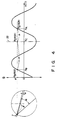
- Scanning position XC (see Fig. 4) or the like corresponding to a target slice whose slice image is desired, is entered via the input device 21.
- the X-ray tube 7 is rotated at a given cycle ⁇ while sliding the patient platform 11 on which the object P is placed, at a constant velocity to carry the body P inside the scanning space 3, whereby the object P is helically scanned at a constant velocity.
- Helical scan data obtained by this helical scan is supplied, together with rotational cycle data of the X-ray tube 7 and scanning position data of the patient platform 11 from the gantry assembly 9, to the interpolation circuit 13.
- the block diagram of the second embodiment is the same as that of the first embodiment.
- the interpolation principle using the counter beams according to the second embodiment is shown in Fig. 7.
- the interpolation circuit 13 first calculates the projection data having the projection angel ⁇ from the counter beams b1, b2, ... b n . Then, the interpolation circuit 13 calculates interpolation data P C ( ⁇ , ⁇ ) of a point C on the slice 22, using projection data P A ( ⁇ , ⁇ ) and P′ B ( ⁇ , ⁇ ) of two scanning positions X′ B and X A on the helix.
- the scanning position X′ B corresponds to the middle point between the scanning position of the X-ray tube 71 and that of the X-ray tube 7 n .
- the interpolation includes the less error due to the difference of the scanning position.
- the present invention is not limited to the above-described embodiment, but may be modified in various manners.
- radiation rays are not restricted to X-rays but may take another form, such as gamma rays.
- the practical method for realizing the helical scan is not limited to what has been described above, and the arrangement of the X-ray tube and detectors can be properly altered.
- the helical scan velocity determined in accordance with the moving velocity of the patient platform and rotational velocity of the X-ray tube is assumed to be constant in the embodiment, it does not necessarily be constant as long as this velocity is known, since the distance between points in different slices can be acquired on the basis of the scan velocity.
- the interpolation data for a slice is acquired from data of two points through a linear interpolation of the first order, it may be acquired through a nonlinear interpolation of the second order or greater or through a spline interpolation. Further, it is possible to interpolate the projection data of the desired slice from more than two data having the same projection angle.
- projection data equivalent to the one acquired when the same slice is scanned can be obtained by interpolating data obtained by the helical scan, thereby eliminating artifact which is the shortcoming of the conventional helical scan.
Abstract
Description
- The present invention relates to a computerized tomographic (CT) apparatus utilizing radiation rays such as X-rays, and, more particularly, to a CT apparatus which performs helical scan to acquire projection data.
- CT apparatuses of the above mentioned type recently become popular since they can scan a wide examining region of an object to be examined in a short period of time. One example of such CT apparatuses is a computerized tomographic apparatus utilizing a radiation source, disclosed in United States Patent No. 4,630,202. The helical scan is a system to move the object in a given direction by permitting the patient platform of a gantry assembly on which the object is placed to slide in the direction of the body axis of the object, and rotate an X-ray tube around the object to continuously scan it. If it is assumed that the object is fixed, the locus of the movement of the X-ray tube relative to the object forms a helix. The pitch of the helix corresponds to the moving velocity of patient platform. In the ordinary dynamic scan and multi-scan, with the object being fixed, the X-ray tube is always rotated within the same slice.
- In reconstructing an image from projection data acquired by the helical scan, projection data for one helical turn may be processed as one set of projection data for acquire one slice image. In this case, however, since projection data for a projection angle of 0° differs from that for a projection angle of 360° by the distance corresponding to the pitch of the helix, some inconsistency will naturally occur in image reconstruction. This is likely to cause an artifact such as a streak on a reconstructed slice image. This event becomes more prominent as the distance corresponding to the pitch of the helix is increased to speed up data acquisition.
- To prevent such shortcoming, according to the aforementioned United States patent, data from 0° to (360 + α)° is acquired as one set of projection data, and data from 0° to α° is smoothed using data from 360° to α° in order to eliminate the above inconsistency. This method is, however, simply to cause the data for 0° and the data for 360° to come within the same slice, and not to cause data for the whole 360° to come within the same slice (plane). Therefore, the artifact cannot be eliminated completely.
- It is an object of the present invention to provide a computerized tomographic apparatus capable of attaining a slice image with less artifact in reconstructing an image based on data acquired through helical scan.
- A computerized tomographic apparatus according to the present invention comprises scanner means for moving an object in one direction and rotating radiation rays within a plane intersecting a moving direction of the object to perform helical scan on the object in order to provide projection data, and interpolation means for interpolating a projection data of a predetermined slice and having a given projection angle in accordance with two projection data of two slices located on both sides of the predetermined slice and having the given projection angle and a distances between the two slices and the predetermined slice.
- Additional objects and advantages of the invention will be set forth in the description which follows, and in part will be obvious from the description, or may be learned by practice of the invention. The objects and advantages of the invention may be realized and obtained by means of the instrumentalities and combinations particularly pointed out in the appended claims.
- This invention can be more fully understood from the following detailed description when taken in conjunction with the accompanying drawings, in which:
- The accompanying drawings, which are incorporated in and constitute a part of the specification, illustrate presently preferred embodiments of the invention and, together with the general description given above and the detailed description of the preferred embodiments given below, serve to explain the principles of the invention.
- Fig. 1 is a block diagram of a CT apparatus according to a first embodiment of the present invention;
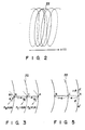
- Fig. 2 is a diagram illustrating a locus of movement of an X-ray tube in the helical scan;
- Fig. 3 is a diagram illustrating the interpolation principle according to the present invention;
- Fig. 4 is a diagram giving a detailed illustration of the principle shown in Fig. 3;
- Fig. 5 is a diagram illustrating the interpolation principle when the speed of the helical scan is not constant;
- Fig. 6 is a view explaining a projection data formed by counter beams which is used in a second embodiment of the present invention; and
- Fig. 7 is a diagram illustrating the interpolation principle according to the second embodiment.
- Embodiments of a CT apparatus according to the present invention will now be described with reference to the accompanying drawings. Fig. 1 is a block diagram of a first embodiment of an X-ray CT apparatus according to the present invention. A
housing dome 1, which incorporates an X-ray tube, a detector and other components, has its center portion open cylindrically in the horizontal direction to define a scanning space 3. Within the dome around the space 3 is provided a detector array 5 which has many X-ray detectors arranged circumferentially. An X-ray tube 7 is disposed rotatable around the array 5. The X-ray tube 7 can be continuously rotated by using a slip ring. This scan system is a modification of a so-called fourth generation scan system which has detectors arranged circumferentially and an X-ray tube disposed rotatable inward of the detector arrangement. A gantry assembly 9 is connected to the front of thedome 1, and a patient platform 11 on which an object P is to be placed slides on the gantry assembly 9 to carry the object P into the scanning space 3. - When the patient platform 11 carrying the object P is slided in the space 3, the X-ray tube 7 irradiates a fan-shaped X-ray onto the object P while rotating around the imaginary axis which passes the center of the space 3 and lies within the object P. By moving the patient platform 11 and rotating the X-ray tube 7 at the same time, the object P is scanned helically with X-rays. The detector array 5 detects the X-rays from the X-ray tube 7 which have penetrated the object P. As the X-ray tube 7 is located outside the detector array 5, there are two detectors positioned along the radiation path of the X-rays, one closest to the tube 7 and the other opposite to the former one. In order to set the closest detector off the radiation path, therefore, the array 5 performs a nutation movement when X-rays are irradiated. Therefore, this system is called a nutation/rotation system.
- Since such the continuous rotation and the nutation/rotation system can permit movement of the patient platform and rotation of the X-ray tube both continuously without interruption, the helical scan can be easily realized. It is noted that even with the use of the so-called third generation and fourth generation scanning system in which the X-ray tube is not continuously rotated, the helical scan can be executed if the sliding of the patient platform is performed when X-ray is irradiated. Further, the helical scan can be executed with the use of the third generation scanning system having a slip ring.
- A detection signal from the detector array 5 is output from the
dome 1 and is supplied to aninterpolation circuit 13. Thiscircuit 13 is also supplied with a signal from thedome 1, which represents the rotational velocity (rotational cycle τ) of the X-ray tube 7 as well as a signal from the gantry assembly 9, which represents the scanning position x(t) of the patient platform 11. Theinterpolation circuit 13 performs a pre-process, such as amplification, integration or D/A conversion, on the detection signal obtained by the detector array 5, thereby preparing projection data for each projection angle. Based on the rotational velocity data of the X-ray tube 7 and the scanning position data of the patient platform 11, theinterpolation circuit 13 performs an interpolation processing (to be described later) on the projection data acquired by the helical scan, and outputs interpolation data which is equivalent to the projection data acquired when the X-ray tube is rotated within the same slice of the object. - In the helical scan, if it is assumed that the object is fixed, the locus of the relative movement of the X-ray tube 7 to the object becomes helical as indicated by the broken line and the solid line in Fig. 2. This helical scan data does not therefore include projection data of one slice, so that the
interpolation circuit 13 acquires, thought interpolation, projection data for 360° of a predetermined slice as indicated by the one-dot chain line as shown in Fig. 2 from the helical scan data for two turns indicated by the solid line. - The projection data (interpolation data) from the
interpolation circuit 13 is supplied to animage reconstruction circuit 15 where image reconstruction is performed. Reconstructed image data is supplied to and stored in animage store 17 which uses a recording medium such as a hard disk. The image data is also supplied to adisplay device 19 comprising a CRT which in turn displays a slice image or the like of the object P. The embodiment further comprises an input device 21 such as a keyboard through which a scanning position for specifying a slice for which interpolation data is to be acquired, is entered. - A description will now be given of the principle of the interpolation carried out by the
interpolation circuit 13. Theinterpolation circuit 13 acquires interpolation data for each point on aslice 22 shown in Fig. 3 by performing linear interpolation of scan data of two adjoining points on the helix which have the same projection angle. Fig. 3 shows the locus of the X-ray tube which is also the locus of the detectors. In practice, projection data is obtained for each channel ϑ. The channel is part of a fan-shaped X-ray beam and is expressed by the following equation:
ϑ = Δϑ·i (1) - Δϑ is a channel pitch and i is the number of detector channels (1 ≦ i ≦ total number of detectors of the detector array 5).
- The
interpolation circuit 13 calculates interpolation data PC(φ, ϑ) of a point C on theslice 22, using projection data PA(φ, ϑ) and PB(φ, ϑ) of two adjacent points A and B on the helix which have the same projection angle φ as the point C and an interpolation ratio α as follows.
PC(φ, ϑ) = α·PA(φ, ϑ) + (1 - α)·PB(φ, ϑ) (2) - α is expressed by the ratio of the differences between the scanning positions XA, XB, and XC of the points A, B, and C as follows.
α = (XC - XB) / (XA - XB) (3) - If at least one of the rotational velocity of the X-ray tube 7 and the sliding speed of the patient platform is not constant, there may be no projection data at the adjacent point, for example, the point A as shown in Fig. 5. To properly deal with this case, first projection data of point A is obtained through interpolation from projection data of two points A′ and A˝ at the proximity of the point A. The interpolation ration β in this case can be acquired from the projection angles of individual points A′, A, and A˝. For the subsequent computation, the same as has previously been described can apply.
- The operation of this embodiment will be described below. Scanning position XC (see Fig. 4) or the like corresponding to a target slice whose slice image is desired, is entered via the input device 21. The X-ray tube 7 is rotated at a given cycle τ while sliding the patient platform 11 on which the object P is placed, at a constant velocity to carry the body P inside the scanning space 3, whereby the object P is helically scanned at a constant velocity. Helical scan data obtained by this helical scan is supplied, together with rotational cycle data of the X-ray tube 7 and scanning position data of the patient platform 11 from the gantry assembly 9, to the
interpolation circuit 13. Thiscircuit 13 performs aforementioned various pre-processes on the helical scan data to provide projection data, then performs interpolation of this projection data according to the aforementioned equation (2) to thereby acquire projection data of each projection angle in theslice 22 for each channel. The interpolation data is supplied to theimage reconstruction circuit 15 where an image reconstruction is executed. The resultant image data is sent to, and stored in, theimage store 17. This image data is also supplied to thedisplay device 19 which, based on the interpolation data, displays the image of an arbitrary slice of the object. - According to this embodiment, projection data on a desired slice can be interpolated from data of adjacent two points on a helix having the same projection angle in accordance with the distances between the two points and the desired slice. Accordingly, a slice image without artifact can be obtained. Even if the moving velocity of the patient platform and the rotational velocity of the X-ray tube are increased to ensure high helical scan, the aforementioned interpolation can be executed, thus preventing any artifact from occurring. Further, a spatial resolution in the moving direction of the patient platform 11 is increased, since the slice image of the arbitrary scanning position can be obtained.
- A second embodiment utilizing projection data formed of counter beams will be described. The X-ray beam transmitted through the object in one direction and the counter X-ray beam transmitted through the object in the opposite direction have the same projection data. Therefore, as shown in Fig. 6, even if the X-ray tube 7′ does not irradiate the X-rays at the projection angel φ, the projection data having the projection angle φ can be obtained by the X-ray counter beams b₁, b₂, ... bn irradiated from the
X-ray tubes 7₁, 7₂, ... 7n. - The block diagram of the second embodiment is the same as that of the first embodiment. The interpolation principle using the counter beams according to the second embodiment is shown in Fig. 7. In the second embodiment, the
interpolation circuit 13 first calculates the projection data having the projection angel φ from the counter beams b₁, b₂, ... bn. Then, theinterpolation circuit 13 calculates interpolation data PC(φ, ϑ) of a point C on theslice 22, using projection data PA(φ, ϑ) and P′B(φ, ϑ) of two scanning positions X′B and XA on the helix. The scanning position X′B corresponds to the middle point between the scanning position of the X-ray tube 71 and that of the X-ray tube 7n. The interpolation is expressed as follows.
PC(φ, ϑ) = α′·PA(φ, ϑ) + (1 - α′)·P′B(φ, ϑ) (4) - α′ is expressed by the ratio of the differences between the scanning positions XA, X′B, and XC as follows.
α′ = (XC - X′B) / (XA - X′B) (5) - According to the second embodiment, the projection data obtained by using the counter beams having a scanning position X′B which is closer to the desired position XC than the position XB as in the first embodiment. Therefore, the interpolation includes the less error due to the difference of the scanning position.
- The present invention is not limited to the above-described embodiment, but may be modified in various manners. Although the foregoing description of the embodiment has been given with reference to an X-ray CT apparatus, radiation rays are not restricted to X-rays but may take another form, such as gamma rays. The practical method for realizing the helical scan is not limited to what has been described above, and the arrangement of the X-ray tube and detectors can be properly altered. Further, although the helical scan velocity determined in accordance with the moving velocity of the patient platform and rotational velocity of the X-ray tube is assumed to be constant in the embodiment, it does not necessarily be constant as long as this velocity is known, since the distance between points in different slices can be acquired on the basis of the scan velocity. Although the interpolation data for a slice is acquired from data of two points through a linear interpolation of the first order, it may be acquired through a nonlinear interpolation of the second order or greater or through a spline interpolation. Further, it is possible to interpolate the projection data of the desired slice from more than two data having the same projection angle.
- As described above, according to the present invention, projection data equivalent to the one acquired when the same slice is scanned can be obtained by interpolating data obtained by the helical scan, thereby eliminating artifact which is the shortcoming of the conventional helical scan.
- Additional advantages and modifications will readily occur to those skilled in the art. Therefore, the invention in its broader aspects is not limited to the specific details, representative devices, and illustrated examples shown and described herein. Accordingly, various modifications may be made without departing from the sprit or scope of the general inventive concept as defined by the appended claims and their equivalents.
Claims (5)
scanning means for moving an object in one direction and for rotating radiation rays within a plane intersecting a moving direction of said object to perform helical scan on said object, thereby to provide projection data, characterized by further comprising:
interpolation means (13) for interpolating a projection data of a predetermined slice and having a given projection angle in accordance with two projection data of two slices located on both sides of the predetermined slice and having the given projection angle and a distances between the two slices and the predetermined slice.
PC(φ, ϑ) = α·PA(φ, ϑ) + (1 -α)·PB(φ, ϑ)
where α is an interpolation ratio and is expressed as follows,
α = (XC - XB) / (XA - XB)
where XA - XB and XC - XB are a distance between the two slices and a distance between the predetermined slice and one of the two slices which corresponds to the projection data PB(φ, ϑ).
means for calculating projection data P′B(φ, ϑ) of a first slice and having a projection angle φ from counter beams; and
means for interpolating the projection data PC(φ, ϑ) of the predetermined slice and having the projection angle φ in accordance with a projection data PA(φ, ϑ) of a second slice and having the projection angle φ and the projection data P′B(φ, ϑ) of the first slice as follows,
PC(φ, ϑ) = α′·PA(φ, ϑ) + (1 - α′)·P′B(φ, ϑ)
where α′ is an interpolation ratio and is expressed as follows,
α′ = (XC - X′B) / (XA - X′B)
where XA - X′B and XC - X′B are a distance between the first slice and the second slice and a distance between the predetermined slice and the first slice.
image reconstruction means (15) for processing an output of said interpolation means; and
means (19) for displaying an output of said image reconstruction means.
moving said object in one direction while rotating radiation rays within a plane intersecting a moving direction of said object, to perform helical scan on said object, thereby providing helical scan data;
designating a desired slice of said object;
reconstructing an image of the desired slice based on the projection data, characterized by further comprising the step of:
interpolating a projection data at the desired slice and having a given projection angle in accordance with two helical scan data at two slices located on both sides of the desired slice and a distance between said two slices and the desired slice.
Applications Claiming Priority (2)
| Application Number | Priority Date | Filing Date | Title |
|---|---|---|---|
| JP31016/89 | 1989-02-13 | ||
| JP1031016A JPH0728862B2 (en) | 1989-02-13 | 1989-02-13 | CT device |
Publications (3)
| Publication Number | Publication Date |
|---|---|
| EP0383232A2 true EP0383232A2 (en) | 1990-08-22 |
| EP0383232A3 EP0383232A3 (en) | 1992-06-10 |
| EP0383232B1 EP0383232B1 (en) | 1996-10-30 |
Family
ID=12319740
Family Applications (1)
| Application Number | Title | Priority Date | Filing Date |
|---|---|---|---|
| EP90102712A Expired - Lifetime EP0383232B1 (en) | 1989-02-13 | 1990-02-12 | Computerized tomographic apparatus |
Country Status (4)
| Country | Link |
|---|---|
| US (1) | US5073911A (en) |
| EP (1) | EP0383232B1 (en) |
| JP (1) | JPH0728862B2 (en) |
| DE (1) | DE69028999T2 (en) |
Cited By (12)
| Publication number | Priority date | Publication date | Assignee | Title |
|---|---|---|---|---|
| EP0426464A2 (en) * | 1989-11-02 | 1991-05-08 | General Electric Company | Computerized tomographic image reconstruction method for helical scanning |
| EP0450152A1 (en) * | 1990-04-04 | 1991-10-09 | Kabushiki Kaisha Toshiba | Computerized tomographic imaging method and apparatus utilizing data interpolation for helical scanning |
| EP0471455A2 (en) * | 1990-08-14 | 1992-02-19 | Picker International, Inc. | Imaging apparatus and methods |
| EP0483729A1 (en) * | 1990-11-01 | 1992-05-06 | Kabushiki Kaisha Toshiba | Method and apparatus for helical scan imaging in X-ray computed tomography |
| EP0504855A2 (en) * | 1991-03-20 | 1992-09-23 | Kabushiki Kaisha Toshiba | X-ray computerized tomography apparatus |
| FR2679435A1 (en) * | 1991-07-24 | 1993-01-29 | Elscint Ltd | MULTI-SLOT COMPUTERIZED TOMOGRAPHY SYSTEM. |
| EP0531993A1 (en) * | 1991-09-12 | 1993-03-17 | Kabushiki Kaisha Toshiba | X-ray computerized tomographic imaging method and imaging system capable of forming scanogram data from helically scanned data |
| US5396418A (en) * | 1988-10-20 | 1995-03-07 | Picker International, Inc. | Four dimensional spiral volume imaging using fast retrace |
| US5485493A (en) * | 1988-10-20 | 1996-01-16 | Picker International, Inc. | Multiple detector ring spiral scanner with relatively adjustable helical paths |
| US6178220B1 (en) | 1996-11-28 | 2001-01-23 | Marconi Medical Systems Israel Ltd. | CT systems with oblique image planes |
| EP1195716A2 (en) * | 2000-10-05 | 2002-04-10 | Philips Corporate Intellectual Property GmbH | Computer tomograph with conical beam and helical relative motion |
| EP1374775A1 (en) * | 2002-06-19 | 2004-01-02 | GE Medical Systems Global Technology Company LLC | Methods and apparatus for multi-slice image reconstruction |
Families Citing this family (21)
| Publication number | Priority date | Publication date | Assignee | Title |
|---|---|---|---|---|
| US5233518A (en) * | 1989-11-13 | 1993-08-03 | General Electric Company | Extrapolative reconstruction method for helical scanning |
| US5216601A (en) * | 1989-11-22 | 1993-06-01 | General Electric Company | Method for fan beam helical scanning using rebinning |
| US5208746A (en) * | 1989-11-22 | 1993-05-04 | General Electric Company | Method for helical scanning with a stationary detector using rebinning and splicing to create detector vertex projection sets |
| JPH0787835B2 (en) * | 1990-06-27 | 1995-09-27 | 株式会社東芝 | X-ray tomography system |
| JPH04166138A (en) * | 1990-10-31 | 1992-06-12 | Toshiba Corp | X-ray ct apparatus |
| JP3047928B2 (en) * | 1991-03-18 | 2000-06-05 | 株式会社日立メディコ | X-ray CT system |
| US5412562A (en) * | 1992-04-02 | 1995-05-02 | Kabushiki Kaisha Toshiba | Computerized tomographic imaging method and system for acquiring CT image data by helical dynamic scanning |
| US5224136A (en) * | 1992-06-30 | 1993-06-29 | General Electric Company | Helical scanning computed tomography apparatus with constrained tracking of the x-ray source |
| US5611026A (en) * | 1992-12-21 | 1997-03-11 | General Electric Company | Combining a priori data with partial scan data to project three dimensional imaging of arbitrary objects with computerized tomography |
| DE4321080C1 (en) * | 1993-06-24 | 1994-12-08 | Siemens Ag | Computer tomograph with helical scanning |
| US5390112A (en) * | 1993-10-04 | 1995-02-14 | General Electric Company | Three-dimensional computerized tomography scanning method and system for imaging large objects with smaller area detectors |
| JPH08308827A (en) * | 1995-05-24 | 1996-11-26 | Ge Yokogawa Medical Syst Ltd | Interpolation data generation method, estimation method for x-ray absorption coefficient abrupt change face position, and x-ray ct |
| US6097784A (en) * | 1998-09-30 | 2000-08-01 | Picker International, Inc. | 3D image reconstruction for helical partial cone beam data |
| US6104775A (en) * | 1998-10-29 | 2000-08-15 | Picker International, Inc. | 3D image reconstruction for helical partial cone beam scanners using wedge beam transform |
| US6790371B2 (en) * | 2001-04-09 | 2004-09-14 | Medtronic, Inc. | System and method for automated separation of blood components |
| US6977984B2 (en) * | 2003-10-07 | 2005-12-20 | Ge Medical Systems Global Technology Company, Llc | Methods and apparatus for dynamical helical scanned image production |
| DE102005053022A1 (en) * | 2005-11-07 | 2007-05-16 | Siemens Ag | Method and device for the spatial representation of an examination area of an examination object |
| JP2007236662A (en) * | 2006-03-09 | 2007-09-20 | Ge Medical Systems Global Technology Co Llc | X-ray ct system, its x-ray ct image reconstitution method and x-ray ct image photographing method |
| DE102006021372B4 (en) * | 2006-05-08 | 2010-02-04 | Siemens Ag | Method for creating a three-dimensional image data set of a target volume and medical examination device |
| JP2012170736A (en) * | 2011-02-23 | 2012-09-10 | Toshiba Corp | X-ray computed tomography apparatus |
| CN103430216A (en) * | 2011-03-15 | 2013-12-04 | 皇家飞利浦有限公司 | Likelihood-based spectral data projection domain de-noising |
Citations (3)
| Publication number | Priority date | Publication date | Assignee | Title |
|---|---|---|---|---|
| US4280178A (en) * | 1979-08-24 | 1981-07-21 | General Electric Company | Computerized tomographic reconstruction method utilizing reflection |
| US4789929A (en) * | 1987-05-14 | 1988-12-06 | Hitachi Medical Corporation | CT system for spirally scanning subject on a movable bed synchronized to X-ray tube revolution |
| NL8800321A (en) * | 1988-02-10 | 1989-09-01 | Philips Nv | Computerised tomography for medical diagnosis - combines rotary movement of X=ray yoke with axial movement of patient for spiral scan |
Family Cites Families (2)
| Publication number | Priority date | Publication date | Assignee | Title |
|---|---|---|---|---|
| JPS59111738A (en) * | 1982-12-16 | 1984-06-28 | 株式会社東芝 | X-ray tomographic apparatus |
| JPH0767445B2 (en) * | 1985-10-14 | 1995-07-26 | 株式会社日立メディコ | X-ray CT system |
-
1989
- 1989-02-13 JP JP1031016A patent/JPH0728862B2/en not_active Expired - Lifetime
-
1990
- 1990-02-12 DE DE69028999T patent/DE69028999T2/en not_active Expired - Lifetime
- 1990-02-12 EP EP90102712A patent/EP0383232B1/en not_active Expired - Lifetime
-
1991
- 1991-05-28 US US07/707,276 patent/US5073911A/en not_active Expired - Lifetime
Patent Citations (3)
| Publication number | Priority date | Publication date | Assignee | Title |
|---|---|---|---|---|
| US4280178A (en) * | 1979-08-24 | 1981-07-21 | General Electric Company | Computerized tomographic reconstruction method utilizing reflection |
| US4789929A (en) * | 1987-05-14 | 1988-12-06 | Hitachi Medical Corporation | CT system for spirally scanning subject on a movable bed synchronized to X-ray tube revolution |
| NL8800321A (en) * | 1988-02-10 | 1989-09-01 | Philips Nv | Computerised tomography for medical diagnosis - combines rotary movement of X=ray yoke with axial movement of patient for spiral scan |
Cited By (23)
| Publication number | Priority date | Publication date | Assignee | Title |
|---|---|---|---|---|
| US5485493A (en) * | 1988-10-20 | 1996-01-16 | Picker International, Inc. | Multiple detector ring spiral scanner with relatively adjustable helical paths |
| US5262946A (en) * | 1988-10-20 | 1993-11-16 | Picker International, Inc. | Dynamic volume scanning for CT scanners |
| US5396418A (en) * | 1988-10-20 | 1995-03-07 | Picker International, Inc. | Four dimensional spiral volume imaging using fast retrace |
| EP0426464A3 (en) * | 1989-11-02 | 1992-04-29 | General Electric Company | Computerized tomographic image reconstruction method for helical scanning |
| EP0426464A2 (en) * | 1989-11-02 | 1991-05-08 | General Electric Company | Computerized tomographic image reconstruction method for helical scanning |
| EP0450152A1 (en) * | 1990-04-04 | 1991-10-09 | Kabushiki Kaisha Toshiba | Computerized tomographic imaging method and apparatus utilizing data interpolation for helical scanning |
| EP0471455A2 (en) * | 1990-08-14 | 1992-02-19 | Picker International, Inc. | Imaging apparatus and methods |
| EP0471455A3 (en) * | 1990-08-14 | 1993-02-10 | Picker International, Inc. | Imaging apparatus and methods |
| EP0713677A1 (en) * | 1990-08-14 | 1996-05-29 | Picker International, Inc. | Imaging apparatus and methods |
| US5386452A (en) * | 1990-11-01 | 1995-01-31 | Kabushiki Kaisha Toshiba | Method and apparatus for helical scan imaging in X-ray computed tomography |
| US5499283A (en) * | 1990-11-01 | 1996-03-12 | Kabushiki Kaisha Toshiba | Method and apparatus for helical scan imaging in X-ray computed tomography |
| US5224135A (en) * | 1990-11-01 | 1993-06-29 | Kabushiki Kaisha Toshiba | Method and apparatus for helical scan imaging in x-ray computed tomography |
| EP0691104A3 (en) * | 1990-11-01 | 1996-04-03 | Toshiba Kk | Method and apparatus for helical scan imaging in X-ray computed tomography |
| EP0483729A1 (en) * | 1990-11-01 | 1992-05-06 | Kabushiki Kaisha Toshiba | Method and apparatus for helical scan imaging in X-ray computed tomography |
| EP0504855A3 (en) * | 1991-03-20 | 1993-11-18 | Toshiba Kk | X-ray computerized tomography apparatus |
| EP0504855A2 (en) * | 1991-03-20 | 1992-09-23 | Kabushiki Kaisha Toshiba | X-ray computerized tomography apparatus |
| FR2679435A1 (en) * | 1991-07-24 | 1993-01-29 | Elscint Ltd | MULTI-SLOT COMPUTERIZED TOMOGRAPHY SYSTEM. |
| US5412702A (en) * | 1991-09-12 | 1995-05-02 | Kabushiki Kaisha Toshiba | X-ray computerized tomographic imaging method and imaging system capable of forming scanogram data from helically scanned data |
| EP0531993A1 (en) * | 1991-09-12 | 1993-03-17 | Kabushiki Kaisha Toshiba | X-ray computerized tomographic imaging method and imaging system capable of forming scanogram data from helically scanned data |
| US6178220B1 (en) | 1996-11-28 | 2001-01-23 | Marconi Medical Systems Israel Ltd. | CT systems with oblique image planes |
| EP1195716A3 (en) * | 2000-10-05 | 2009-10-21 | Philips Intellectual Property & Standards GmbH | Computer tomograph with conical beam and helical relative motion |
| EP1195716A2 (en) * | 2000-10-05 | 2002-04-10 | Philips Corporate Intellectual Property GmbH | Computer tomograph with conical beam and helical relative motion |
| EP1374775A1 (en) * | 2002-06-19 | 2004-01-02 | GE Medical Systems Global Technology Company LLC | Methods and apparatus for multi-slice image reconstruction |
Also Published As
| Publication number | Publication date |
|---|---|
| DE69028999T2 (en) | 1997-06-05 |
| DE69028999D1 (en) | 1996-12-05 |
| US5073911A (en) | 1991-12-17 |
| JPH0728862B2 (en) | 1995-04-05 |
| EP0383232B1 (en) | 1996-10-30 |
| JPH02211129A (en) | 1990-08-22 |
| EP0383232A3 (en) | 1992-06-10 |
Similar Documents
| Publication | Publication Date | Title |
|---|---|---|
| EP0383232A2 (en) | Computerized tomographic apparatus | |
| US4630202A (en) | Computerized tomographic apparatus utilizing a radiation source | |
| US6400789B1 (en) | On-line image reconstruction in helical CT scanners | |
| US6944260B2 (en) | Methods and apparatus for artifact reduction in computed tomography imaging systems | |
| EP0467532B1 (en) | Computed tomography system | |
| US7113569B2 (en) | X-ray CT apparatus | |
| US5270923A (en) | Computed tomographic image reconstruction method for helical scanning using interpolation of partial scans for image construction | |
| US5864598A (en) | Methods and apparatus for scanning an object in a computed tomography system | |
| US5559847A (en) | Systems, methods and apparatus for reconstructing images in a CT system implementing a helical scan | |
| US5469486A (en) | Projection domain reconstruction method for helical scanning computed tomography apparatus with multi-column detector array employing overlapping beams | |
| US7154986B2 (en) | Tilted gantry helical cone-beam Feldkamp reconstruction for multislice CT | |
| US5805659A (en) | Method and apparatus for spiral scan region of interest imaging | |
| US5513236A (en) | Image reconstruction for a CT system implementing a dual fan beam helical scan | |
| EP1104917B1 (en) | Methods and apparatus for adaptive interpolation reduced view CT scan | |
| US6381297B1 (en) | High pitch reconstruction of multislice CT scans | |
| US6775347B2 (en) | Methods and apparatus for reconstructing an image of an object | |
| JPH11253435A (en) | Computed tomograph | |
| US20050175144A1 (en) | Methods and apparatus for artifact reduction in cone beam CT image reconstruction | |
| WO2000062674A1 (en) | Half field of view reduced-size ct detector | |
| JP3917684B2 (en) | Method and apparatus for creating a tomographic image of an object | |
| US5546439A (en) | Systems, methods and apparatus for incrementally reconstructing overlapped images in a CT system implementing a helical scan | |
| JP2002136510A (en) | Method and device to obtain submillimeter ct slices with increased coverage | |
| US6154515A (en) | Computerized tomography reconstruction using shadow zone patching | |
| EP0450152B1 (en) | Computerized tomographic imaging method and apparatus utilizing data interpolation for helical scanning | |
| EP0333857B1 (en) | Radiation ct |
Legal Events
| Date | Code | Title | Description |
|---|---|---|---|
| PUAI | Public reference made under article 153(3) epc to a published international application that has entered the european phase |
Free format text: ORIGINAL CODE: 0009012 |
|
| 17P | Request for examination filed |
Effective date: 19900212 |
|
| AK | Designated contracting states |
Kind code of ref document: A2 Designated state(s): DE FR NL |
|
| PUAL | Search report despatched |
Free format text: ORIGINAL CODE: 0009013 |
|
| AK | Designated contracting states |
Kind code of ref document: A3 Designated state(s): DE FR NL |
|
| 17Q | First examination report despatched |
Effective date: 19941229 |
|
| GRAG | Despatch of communication of intention to grant |
Free format text: ORIGINAL CODE: EPIDOS AGRA |
|
| GRAH | Despatch of communication of intention to grant a patent |
Free format text: ORIGINAL CODE: EPIDOS IGRA |
|
| GRAH | Despatch of communication of intention to grant a patent |
Free format text: ORIGINAL CODE: EPIDOS IGRA |
|
| GRAA | (expected) grant |
Free format text: ORIGINAL CODE: 0009210 |
|
| AK | Designated contracting states |
Kind code of ref document: B1 Designated state(s): DE FR NL |
|
| REF | Corresponds to: |
Ref document number: 69028999 Country of ref document: DE Date of ref document: 19961205 |
|
| ET | Fr: translation filed | ||
| PLBE | No opposition filed within time limit |
Free format text: ORIGINAL CODE: 0009261 |
|
| STAA | Information on the status of an ep patent application or granted ep patent |
Free format text: STATUS: NO OPPOSITION FILED WITHIN TIME LIMIT |
|
| 26N | No opposition filed | ||
| PGFP | Annual fee paid to national office [announced via postgrant information from national office to epo] |
Ref country code: DE Payment date: 20090206 Year of fee payment: 20 Ref country code: NL Payment date: 20090203 Year of fee payment: 20 |
|
| PGFP | Annual fee paid to national office [announced via postgrant information from national office to epo] |
Ref country code: FR Payment date: 20090213 Year of fee payment: 20 |
|
| NLV7 | Nl: ceased due to reaching the maximum lifetime of a patent |
Effective date: 20100212 |
|
| PG25 | Lapsed in a contracting state [announced via postgrant information from national office to epo] |
Ref country code: DE Free format text: LAPSE BECAUSE OF EXPIRATION OF PROTECTION Effective date: 20100212 |