EP0466555A1 - Local network for intercommunication between data processing modules - Google Patents
Local network for intercommunication between data processing modules Download PDFInfo
- Publication number
- EP0466555A1 EP0466555A1 EP91401815A EP91401815A EP0466555A1 EP 0466555 A1 EP0466555 A1 EP 0466555A1 EP 91401815 A EP91401815 A EP 91401815A EP 91401815 A EP91401815 A EP 91401815A EP 0466555 A1 EP0466555 A1 EP 0466555A1
- Authority
- EP
- European Patent Office
- Prior art keywords
- bus
- data
- data processing
- transfers
- transfer
- Prior art date
- Legal status (The legal status is an assumption and is not a legal conclusion. Google has not performed a legal analysis and makes no representation as to the accuracy of the status listed.)
- Withdrawn
Links
Images


Classifications
-
- H—ELECTRICITY
- H04—ELECTRIC COMMUNICATION TECHNIQUE
- H04L—TRANSMISSION OF DIGITAL INFORMATION, e.g. TELEGRAPHIC COMMUNICATION
- H04L12/00—Data switching networks
- H04L12/28—Data switching networks characterised by path configuration, e.g. LAN [Local Area Networks] or WAN [Wide Area Networks]
- H04L12/40—Bus networks
- H04L12/403—Bus networks with centralised control, e.g. polling
-
- G—PHYSICS
- G06—COMPUTING; CALCULATING OR COUNTING
- G06F—ELECTRIC DIGITAL DATA PROCESSING
- G06F13/00—Interconnection of, or transfer of information or other signals between, memories, input/output devices or central processing units
- G06F13/14—Handling requests for interconnection or transfer
- G06F13/36—Handling requests for interconnection or transfer for access to common bus or bus system
Definitions
- the field of the invention is that of local area networks for putting data processing modules into communication, allowing each module to send data to another module connected to the network, and to receive data sent to it from the network. .
- These data processing modules can for example be processor cards, called “computers”, or interfaces to other communication networks having characteristics different from the first network (for example long distance networks).
- the computers are in particular used to carry out signal processing, that is to say to carry out on a signal a certain number of successive operations on data which arrive in large numbers.
- signal processing that is to say to carry out on a signal a certain number of successive operations on data which arrive in large numbers.
- networks consisting of several one-way links forming a circulating or closed network, provided with a decentralized arbitration system which does not consume bandwidth.
- These networks are advantageous for the interconnection of computing units, or machines (autonomous sets of processor cards) because, the distribution of processing between these units being generally quasi-static, the network topology can be optimized, once and for all , depending on communications needs.
- these networks have the drawback of having variable performance depending on the position, in the network topology, of the subscribers who communicate.
- control communications which make it possible to synchronize the modules, exchange macroscopic (global) results or status information
- raw data communications which are the data to be processed, intermediate result tables, output result tables and downloads of programs or of parameter and calculation tables.
- Control communications due to their random nature and their high priority level, require that the programming of each data processing module is as independent as possible from that of the other modules from the input / output point of view, and that any module can send any number of data to any subset of the other modules at any time.
- a bus comprising a centralized access arbitration which can be complex, therefore increases the complexity of the interface to the bus and the number of bus lines and decreases the time available for transfers because of the duration of the arbitrations.
- the flow rate of this type of bus called "supervisor" is therefore low.
- Raw data communications are exchanged on a permanent and recurring basis and their progress is organized by the programmer during the development of the software architecture of the system. They therefore do not have the random nature of communications of the "control" type and they constitute, in essence, a relationship of dependence between the processes developed in the different data processing modules, and therefore between the programs of these modules.
- the exchange speed is high, for these data communications it is essential to use a bus allowing a fast speed and whose available bandwidth is used at best.
- the quantity of components allocated to the interface to the bus be reduced so that the modules have a high processing power and it is also desirable that the number of lines of the bus is reduced in order to simplify the connection or to allow the connection of the data processing modules to other communication networks.
- the subject of the invention is therefore a high speed local area network which in particular makes it possible to overcome the various drawbacks of existing networks and which makes it possible to facilitate the use of large information processing systems.
- the invention consists in making a local intercommunication network comprising two types of interconnection bus: a first type of bus called “supervisor", intended to be used for communications of the control type and which can be carried out so conventional for example using a bus comprising an arbitration, and a second type of broadband bus intended to be used for communications of the "raw data" type which does not comprise arbitration and has electronic simple interface, reduced number of lines and available bandwidth used to best advantage.
- a first type of bus called “supervisor”
- broadband bus intended to be used for communications of the "raw data” type which does not comprise arbitration and has electronic simple interface, reduced number of lines and available bandwidth used to best advantage.
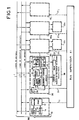
- FIG 1 shows the block diagram of the local intercommunication network according to the invention.
- the network comprises at least one supervisor bus B1, of known principle but not described, and at least one high speed B2 bus, comprising three types of lines on which the information circulates. These lines are control lines, 1, description lines of transfers, 2, and data lines 3. On these different lines are connected two kinds of modules: master modules, 10j, and slave modules, 20i, the slave modules being associated with data processing modules, 30i.
- the two types of bus communicate with each other via links 11j, 21i, i being an index varying from 1 to n, and n representing the number of data processing modules connected to the bus B2, j being an index varying from 1 to p , p being the number of master modules of the bus B2.
- Bus B1 supervisor at the bus B2 the characteristics of the transfers to be made between data processing modules, or subscriber computers 30i, and for each transfer, the nature of the operation to be carried out.
- the bus B2 is equipped with at least one master module 10 and as many slave modules 20i as there are data processing modules called computers 30i, and any computer 30i can be equipped with a master module 10j.
- master module 10 When the bus has several master modules, only one must be active at a time; also, among the control lines, 1, there is a line which ensures the mutual exclusion of the master modules in the event that one or more supervisor buses attempt to activate several of these modules simultaneously.
- the active master module 10 generates the internal clock of the bus B2 and manages the data transfers; for this it uses the control lines 1 and the description lines of the transfers 2, while the slave modules use the information circulating on the lines 1 and 2 and execute the data transfers between the data lines 3 and the computers 30i.
- the master module 10 essentially comprises, connected in series, a RAM memory 12, a sequencer 13 and a transfer pointer, 14.
- the RAM memory 12 receives, via the link 11 with the supervisor bus B1, the characteristics of the transfers to be carried out . These characteristics are the size, the source and the destination of the transfers to be carried out corresponding respectively to the number of blocks to be transmitted, to the number of the transmitter (that is to say the number of the computer transmitting the data to be transmitted), and to a code called phase number allowing to particularize the transfer.
- the transmitter number and the phase number are then transmitted to all the slave modules, 20i, on the description lines of the transfers 2, while the number of blocks is transmitted from the memory 12 to the sequencer 13 which uses it. to manage the transfer pointer, 14.
- the sequencer, 13 increments the transfer pointer 14 which then points to a new transfer in the list then activates one of the control lines, 1, to indicate to the slave modules 20i that the characteristics of a new transfer are present on the description lines of the transfers , 2.
- the sequencer 13 also has the role of creating the clock of the bus B2 on one of the control lines 1. This clock is used by the slave modules 20i to synchronize the exchanges of data.
- the slave modules transmitting the data activate one of the control lines, 1, and the sequencer 13 then adds a half clock cycle to the normal duration of the clock cycle in order to increase the time. available for transmitter switching with respect to the time normally allocated for the transfer of each data. This last time can therefore be made minimum and the bandwidth of the bus lines is thus better used.
- the slave module, 20 essentially comprises a buffer register T1, 24, receiving the characteristics of each transfer to be performed and resynchronizing them, a RAM memory 22 called “instruction memory”, a sequencer 23, a memory address generator 25 for the memory 31 of the computer 30 and an interface 19 for transferring data between the bus B2 and the computer 30.
- the interface 19 for transferring the data is shown diagrammatically in FIG. 1 by switches 26, 27 intended for selecting the direction of transmission data and by buffer registers T2, 28 and T3, 29, intended to synchronize the data.
- the RAM 22 receives, via the buffer register T1, 24, the phase number corresponding to each transfer, and via the link 21 with the supervisor bus B1, the instruction to execute for each transfer.
- This instruction is part of a set of three possible instructions which are: send data on bus B2, receive data from bus B2, do nothing, these instructions being respectively denoted EMI, REC, NOT.
- the instruction pointed by the phase number in the memory 22 is EMI
- the transmitter number from the description lines of the transfers 2 is compared with a subscriber number before the execution of the transfer.
- the subscriber number is wired to each of the subscriber computers 30 and is specific to each of them. It avoids a conflict on data lines 3 if several subscribers have the same EMI instruction for the same phase number.
- the instruction from memory 22 is used by the sequencer 23 to manage the memory address generator 25 and the switches 26 and 27.
- the memory address generator 25 When the memory address generator 25 is activated by the sequencer 23, that is to say say when the instruction from memory 22 is not NOT, it uses the phase number from transfer lines 2 to determine the address of the data located in a memory 31 internal to the subscriber computer, 30.
- the generator of memory addresses 25 supplies the memory 31 of the subscriber computer 30 with control signals, such as read or write signals, and address signals making it possible to store or extract therein the data to be transferred .
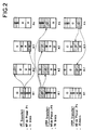
- FIG. 2 shows an example of operation of the intercommunication bus, according to the invention, in the case where three transfers must be carried out between sub-assemblies of a group of four subscribers denoted A1, A2, A3, A4; these three transfers having to be carried out successively from a single launch order applied by the supervisor bus B1 to the active master module 10.
- phase numbers associated respectively with these three transfers are for example P1, P9, and P4.
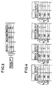
- FIG. 3 shows the programming, by the supervisor bus B1, of the active master module for carrying out the transfers of FIG. 2.
- the memory 12 of the master module 10 containing the list of transfers to be carried out must be programmed by the supervisor bus B1 of as follows: the first, second, third lines respectively describe the characteristics of the first, second and third transfers to be carried out. These lines contain the number of blocks, the transmitter number and the phase number of each of the transfers to be made.
- the first line corresponding to the first transfer contains a number of blocks equal to 11, a transmitter number equal to A1 and a phase number equal to P1.
- the second line has a number of blocks equal to 30, a transmitter number equal to A1 and a phase number equal to P9.
- the third line has a number of blocks equal to 25, a transmitter number equal to A4 and a phase number equal to P4.
- the three transfers are carried out successively by means of the pointer 14 which counts for each transfer, therefore for each phase number, the number of blocks already transmitted. and who goes to transfer programmed next when the last block corresponding to the current phase number is transferred.
- FIG. 4 shows the programming, by the supervisor bus B1, of the slave modules 20 of the four subscribers A1, A2, A3, A4, for carrying out the transfers of FIG. 2.
- the instruction memories 22 of the slave modules 20 of the subscribers A1, A2, A3, A4 and the buffer description memories included in the address generators 25 of these same slave modules must be programmed by the supervisor bus B1.
- the instruction memories 22 are addressed by the phase number lines coming from the description lines of the transfers 2, themselves activated by the master module in service in accordance with the content of its memory 12 programmed according to FIG. 3.
- the phase numbers P1, P4 and P9 being the only ones capable of being sent by the master module in service, only the addresses of the memories 22 corresponding to these phase numbers are to be programmed.
- the phase number sent by the master module in service is P1 and the subscriber A1 must send, while the subscribers A2 and A3 must receive the data sent by A1.
- the instruction memories 22 and the buffer management of the subscribers are therefore programmed in the following manner: the subscriber A1 has an EMI instruction and a buffer number to be addressed equal to 3.
- Subscriber A2 has a REC instruction and a buffer number to be addressed equal to 1.
- Subscriber A3 has a REC instruction and a buffer number to be addressed equal to 4.
- Subscriber A4 has a NOT instruction and a buffer number to be addressed which remains blank.
- the addresses P4 and P9 of the instruction memories 22 and of the buffer management memories are programmed in the same way as for the address P1 in accordance with FIG. 4, that is to say that for the address P4 the subscribers A1, A2, A3, A4 respectively have a NOT, REC, REC, EMI instruction and a buffer number to address equal to nothing respectively, 3, 3, 5.
- For address P9 subscribers A1, A2, A3, A4 respectively have an EMI, REC, REC, REC instruction, and a buffer number to be addressed equal to 1, 2 respectively , 1, 4.
- an intercommunication network has been produced having the following characteristics: 32 data lines, 4 control lines, 10 transfer description lines, a data block size equal to 32 words, ie 128 bytes, a number of subscribers less than or equal to 16, a maximum speed of use equal to 48 M bytes / second which corresponds to a maximum distance between any two subscribers connected to the B2 bus less than the width of a bay 19 inch electronics, less than 44 cm.
- the 32 data lines ensure the transfer of data between the different subscribers.
- FIG. 5 represents an exemplary embodiment of a master module, according to the invention.
- FIG. 6 represents an exemplary embodiment of a slave module, according to the invention.
- the sequencer 44 manages the entire slave module.
- the state of the description lines of the transfers 2 is stored in the buffer register 24.
- the sequencer 44 decodes the instruction coming from subfield 41 of the memory 40 and prepares to execute it as soon as the previous transfer is completed, which is indicated to it by deactivation of the BUSY signal.
- the instruction is NOT, the two buffers 49 and 50 are isolated as soon as the previous transfer is completed and no operation is executed until the signal STATVAL is again active.
- the sequencer 44 verifies the result of the comparison between the subscriber number and the phase number using the comparator 46.
- the sequencer 44 performs the following operations: it gives the order to the counter of addresses 47 to load field 42 of memory 40, it validates the data transmission buffer 49, it activates the "selection" and "read” control signals from memory 31 of the computer 30, it activates the BUSY signal, it authorizes the address counter 47 to count.
- the execution of the EMI instruction is finished when the comparator 48 indicates that the last data block has been transferred.
- the sequencer 44 performs the following operations: it gives the order to the address counter 47 to load the field 42 of the memory 40, it validates the data reception buffer 50; then, as soon as the signal BUSY is again active, thus indicating that the transmitter of the new transfer transmits its first data, the sequencer 44 activates the control signals "selection" and “reading” from the memory 31 of the computer 30 and authorizes the address counter 47 to be counted.
- the execution of the instruction REC is terminated as soon as the comparator 48 indicates that the last block of data has been transferred or as soon as the signal BUSY is deactivated, thus indicating that the transmitter has finished transmitting.
Abstract
Description
Le domaine de l'invention est celui des réseaux locaux de mise en communication de modules de traitement de données, permettant à chaque module d'envoyer des données à un autre module connecté au réseau, et de recevoir du réseau les données qui lui sont adressées.The field of the invention is that of local area networks for putting data processing modules into communication, allowing each module to send data to another module connected to the network, and to receive data sent to it from the network. .
Ces modules de traitement de données peuvent être par exemple des cartes processeurs, dites "calculateurs", ou des interfaces vers d'autres réseaux de communication ayant des caractéristiques différentes du premier réseau (par exemple des réseaux longue distance).These data processing modules can for example be processor cards, called "computers", or interfaces to other communication networks having characteristics different from the first network (for example long distance networks).
Les calculateurs sont notamment utilisés pour effectuer du traitement du signal, c'est-à-dire pour réaliser sur un signal un certain nombre d'opérations successives sur des données qui arrivent en nombre important. Quand un calculateur même de forte puissance ne suffit pas, il faut mettre en oeuvre le traitement par plusieurs calculateurs qui doivent donc inter-communiquer.The computers are in particular used to carry out signal processing, that is to say to carry out on a signal a certain number of successive operations on data which arrive in large numbers. When a computer even of high power is not enough, it is necessary to implement the processing by several computers which must therefore inter-communicate.
Il existe des réseaux d'intercommunication de calculateurs constitués par un bus de données linéaire ou circulant fermé, sur lequel viennent se connecter des calculateurs abonnés qui communiquent avec le bus à travers des circuits tampons d'entrée/sortie. Ces bus ont généralement recours à un arbitrage d'accès centralisé, ce qui particularise un ou plusieurs des abonnés. D'autre part, la bande passante totale, et donc le débit total est partagé entre les différents abonnés, ce qui limite le nombre d'abonnés raccordables.There are computer intercommunication networks constituted by a closed linear or circulating data bus, to which subscriber computers are connected which communicate with the bus through input / output buffer circuits. These buses generally use centralized access arbitration, which distinguishes one or more of the subscribers. On the other hand, the total bandwidth, and therefore the total speed is shared between the different subscribers, which limits the number of connectable subscribers.
Il existe également des réseaux permettant une décentralisation de l'arbitrage d'accès. Dans ces réseaux chaque abonné détecte par lui-même si le bus est libre, et résout les problèmes de collision. Ces réseaux décentralisés existants présentent l'inconvénient d'utiliser une partie de la bande passante disponible pour la transmission des données entre les abonnés pour résoudre les problèmes de collision.There are also networks allowing decentralization of access arbitration. In these networks, each subscriber detects for himself whether the bus is free, and resolves collision problems. These existing decentralized networks have the disadvantage of using part of the band bandwidth available for data transmission between subscribers to resolve collision issues.
Enfin, il existe des réseaux constitués de plusieurs liaisons monodirectionnelles formant un réseau circulant ou fermé, munis d'un système d'arbitrage décentralisé qui ne consomme pas de bande passante. Ces réseaux sont avantageux pour l'interconnexion d'unités de calcul, ou machines (ensembles autonomes de cartes processeurs) car, la répartition des traitements entre ces unités étant généralement quasi-statique, la topologie du réseau peut être optimisée, une fois pour toutes, en fonction des besoins de communications. Cependant, ces réseaux présentent l'inconvénient d'avoir des performances variables en fonction de la position, dans la topologie du réseau, des abonnés qui communiquent.Finally, there are networks consisting of several one-way links forming a circulating or closed network, provided with a decentralized arbitration system which does not consume bandwidth. These networks are advantageous for the interconnection of computing units, or machines (autonomous sets of processor cards) because, the distribution of processing between these units being generally quasi-static, the network topology can be optimized, once and for all , depending on communications needs. However, these networks have the drawback of having variable performance depending on the position, in the network topology, of the subscribers who communicate.
Dans les gros systèmes de traitement d'informations en temps réel (radars, sonars, ...) en particulier, les quantités d'informations à échanger sont énormes. Les réseaux doivent assurer le transit de ces informations en plus des échanges classiques propres à tout système informatique distribué.In large real-time information processing systems (radars, sonars, etc.) in particular, the quantities of information to be exchanged are enormous. Networks must ensure the transit of this information in addition to the traditional exchanges specific to any distributed computer system.
La nature des communications, dans le cas notamment d'un gros système de traitement de données en temps réel dans lequel un grand nombre de modules sont interconnectés, sont de deux types : les communications dites de "contrôle" qui permettent de synchroniser les modules, d'échanger des résultats macroscopiques (globaux) ou des informations d'état ; et les communications dites de "données brutes" qui sont les données à traiter, des tableaux de résultats intermédiaires, les tableaux de résultats à sortir et les téléchargements de programmes ou de tables de paramètres et de calculs.The nature of communications, in the case in particular of a large real-time data processing system in which a large number of modules are interconnected, are of two types: so-called "control" communications which make it possible to synchronize the modules, exchange macroscopic (global) results or status information; and so-called "raw data" communications which are the data to be processed, intermediate result tables, output result tables and downloads of programs or of parameter and calculation tables.
Les communications de contrôle, en raison de leur caractère aléatoire et de leur niveau de priorité élevé nécessitent que la programmation de chaque module de traitement de données soit la plus indépendante possible de celle des autres modules du point de vue des entrées/sorties, et que n'importe quel module puisse envoyer un nombre de données quelconque vers un sous-ensemble quelconque des autres modules à n'importe quel moment. Ces exigences conduisent à utiliser un bus comportant un arbitrage d'accès centralisé qui peut être complexe, augmente donc la complexité de l'interface au bus et le nombre de lignes du bus et diminue le temps disponible pour les transferts à cause de la durée des arbitrages. Le débit de ce type de bus dit "superviseur" est donc faible.Control communications, due to their random nature and their high priority level, require that the programming of each data processing module is as independent as possible from that of the other modules from the input / output point of view, and that any module can send any number of data to any subset of the other modules at any time. These requirements lead to using a bus comprising a centralized access arbitration which can be complex, therefore increases the complexity of the interface to the bus and the number of bus lines and decreases the time available for transfers because of the duration of the arbitrations. The flow rate of this type of bus called "supervisor" is therefore low.
Les communications de données brutes sont échangées de manière permanente et récurrente et leur déroulement est organisé par le programmeur lors de l'élaboration de l'architecture logicielle du système. Elles n'ont donc pas le caractère aléatoire des communications de type "contrôle" et elles constituent, par essence, une relation de dépendance entre les processus élaborés dans les différents modules de traitement de données, donc entre les programmes de ces modules. Dans le cas où le débit des échanges est élevé, pour ces communications de données il est primordial d'utiliser un bus permettant un débit rapide et dont la bande passante disponible est utilisée au mieux.Raw data communications are exchanged on a permanent and recurring basis and their progress is organized by the programmer during the development of the software architecture of the system. They therefore do not have the random nature of communications of the "control" type and they constitute, in essence, a relationship of dependence between the processes developed in the different data processing modules, and therefore between the programs of these modules. In the case where the exchange speed is high, for these data communications it is essential to use a bus allowing a fast speed and whose available bandwidth is used at best.
De plus pour ces deux types de communication, il est souhaitable que la quantité de composants allouée à l'interface au bus soit réduite afin que les modules aient une grande puissance de traitement et il est également souhaitable que le nombre de lignes du bus soit réduit afin de simplifier la connectique ou de permettre la connexion des modules de traitement de données à d'autres réseaux de communication.In addition for these two types of communication, it is desirable that the quantity of components allocated to the interface to the bus be reduced so that the modules have a high processing power and it is also desirable that the number of lines of the bus is reduced in order to simplify the connection or to allow the connection of the data processing modules to other communication networks.
Ces deux types de communication ont des exigences contradictoires que les réseaux existants ne permettent pas de satisfaire au mieux. Notamment, d'une part l'utilisation d'un bus comportant un arbitrage d'accès centralisé est suffisant lorsque la quantité d'informations à échanger est faible, tel que c'est le cas pour les communications de contrôle et pour les petits systèmes, mais ce type de bus est incompatible avec les communications de données brutes lorsqu'il s'agit de gros systèmes. D'autre part, les réseaux permettant une décentralisation de l'arbitrage d'accès ne présentent pas non plus un débit suffisant car la bande passante du bus est partagée avec un système anti-collisions.These two types of communication have contradictory requirements which the existing networks do not make it possible to satisfy at best. In particular, on the one hand, the use of a bus comprising centralized access arbitration is sufficient when the quantity of information to be exchanged is small, as is the case for control communications and for small systems. , but this type of bus is incompatible with raw data communications when dealing with large systems. On the other hand, networks allowing decentralization Access arbitration also does not have sufficient throughput because the bus bandwidth is shared with an anti-collision system.
L'invention a donc pour objet un réseau local à haut débit permettant notamment de pallier les divers inconvénients des réseaux existants et permettant de faciliter la mise en oeuvre des gros systèmes de traitement d'informations.The subject of the invention is therefore a high speed local area network which in particular makes it possible to overcome the various drawbacks of existing networks and which makes it possible to facilitate the use of large information processing systems.
Pour cela, l'invention consiste à réaliser un réseau local d'intercommunication comportant deux types de bus d'interconnexion : un premier type de bus dit "superviseur", destiné à être utilisé pour les communications de type contrôle et pouvant être réalisé de manière classique par exemple à l'aide d'un bus comportant un arbitrage, et un deuxième type de bus à haut débit destiné à être utilisé pour les communications de type "données brutes" qui ne comporte pas d'arbitrage et présente une électronique d'interface simple, un nombre de lignes réduit et une bande passante disponible utilisée au mieux.For this, the invention consists in making a local intercommunication network comprising two types of interconnection bus: a first type of bus called "supervisor", intended to be used for communications of the control type and which can be carried out so conventional for example using a bus comprising an arbitration, and a second type of broadband bus intended to be used for communications of the "raw data" type which does not comprise arbitration and has electronic simple interface, reduced number of lines and available bandwidth used to best advantage.
Selon l'invention, le réseau local d'intercommunication de modules de traitement de données, notamment de calculateurs, destiné à transmettre des informations de contrôle et de données brutes, caractérisé en ce qu'il comporte :
- au moins un premier bus B1, dit superviseur, destiné à transmettre les communications de contrôle,
- au moins un deuxième bus B2, à haut débit, destiné à transmettre les communications de données brutes et comportant trois types de lignes de transmission des informations sur lesquelles sont connectés au moins un module maître et autant de modules esclaves que de modules de traitement des données auxquels ils sont reliés, un seul module maître étant actif à la fois, ledit module maître actif étant destiné à coordonner des transferts de données brutes entre les modules de traitement des données selon une séquence programmée par le bus superviseur B1, les transferts étant effectués les uns après les autres par blocs successifs de taille déterminée et les caractéristiques des transferts étant distribuées entre les différents modules esclaves, lesdits modules esclaves étant programmés par le bus superviseur B1 pour effectuer à chaque transfert les actions d'échanges de données sur le bus B2.
- at least a first bus B1, called supervisor, intended for transmitting control communications,
- at least one second high-speed B2 bus intended for transmitting raw data communications and comprising three types of information transmission lines to which at least one master module and as many slave modules as there are data processing modules are connected to which they are connected, only one master module being active at a time, said active master module being intended to coordinate transfers of raw data between the data processing modules according to a sequence programmed by the supervisor bus B1, the transfers being carried out one after the other by successive blocks of determined size and the characteristics of the transfers being distributed between the different slave modules, said slave modules being programmed by the supervisor bus B1 to carry out at each transfer the data exchange actions on the bus B2.
D'autres particularités et avantages de l'invention apparaîtront clairement dans la description suivante donnée à titre d'exemple non limitatif et faite en regard des figures annexées qui représentent :
- la figure 1, le schéma de principe du réseau local d'intercommunication, selon l'invention,
- la figure 2, un exemple de fonctionnement du bus d'intercommunication, selon l'invention,
- la figure 3, la programmation, par le bus superviseur B1, du module maître actif, pour l'exemple de la figure 2,
- la figure 4, la programmation, par le bus superviseur B1, des modules esclaves, pour l'exemple de la figure 2,
- la figure 5, un exemple de réalisation du module maître, selon l'invention,
- la figure 6, un exemple de réalisation du module esclave, selon l'invention.
- FIG. 1, the block diagram of the local intercommunication network, according to the invention,
- FIG. 2, an example of operation of the intercommunication bus, according to the invention,
- FIG. 3, the programming, by the supervisor bus B1, of the active master module, for the example of FIG. 2,
- FIG. 4, the programming, by the supervisor bus B1, of the slave modules, for the example of FIG. 2,
- FIG. 5, an exemplary embodiment of the master module, according to the invention,
- FIG. 6, an exemplary embodiment of the slave module, according to the invention.
La figure 1, représente le schéma de principe du réseau local d'intercommunication, selon l'invention. Le réseau comprend au moins un bus B1 superviseur, de principe connu mais non décrit, et au moins un bus B2 à haut débit, comprenant trois types de lignes sur lesquelles circulent les informations. Ces lignes sont des lignes de contrôle, 1, des lignes de description des transferts, 2, et des lignes de données 3. Sur ces différentes lignes sont connectés deux sortes de modules : des modules maîtres, 10j, et des modules esclaves, 20i, les modules esclaves étant associés à des modules de traitement de données, 30i.Figure 1 shows the block diagram of the local intercommunication network according to the invention. The network comprises at least one supervisor bus B1, of known principle but not described, and at least one high speed B2 bus, comprising three types of lines on which the information circulates. These lines are control lines, 1, description lines of transfers, 2, and
Les deux types de bus communiquent entre eux via des liaisons 11j, 21i, i étant un indice variant de 1 à n, et n représentant le nombre de modules de traitement de données reliés au bus B2, j étant un indice variant de 1 à p, p étant le nombre de modules maîtres du bus B2. Le bus B1 superviseur au bus B2, les caractéristiques des transferts à effectuer entre des modules de traitement de données, ou calculateurs abonnés 30i, et pour chaque transfert, la nature de l'opération à réaliser.The two types of bus communicate with each other via links 11j, 21i, i being an index varying from 1 to n, and n representing the number of data processing modules connected to the bus B2, j being an index varying from 1 to p , p being the number of master modules of the bus B2. Bus B1 supervisor at the bus B2, the characteristics of the transfers to be made between data processing modules, or subscriber computers 30i, and for each transfer, the nature of the operation to be carried out.
Le bus B2 est équipé d'au moins un module maître 10 et d'autant de modules esclaves 20i que de modules de traitement de données dits calculateurs 30i, et n'importe quel calculateur 30i, peut être équipé d'un module maître 10j. Lorsque le bus comporte plusieurs modules maîtres, un seul doit être actif à la fois ; aussi, parmi les lignes de contrôle, 1, se trouve une ligne qui assure l'exclusion mutuelle des modules maîtres dans le cas où un ou plusieurs bus superviseurs tenteraient d'activer plusieurs de ces modules simultanément.The bus B2 is equipped with at least one
Le module maître actif 10 génère l'horloge interne du bus B2 et gère les transferts de données ; il utilise pour cela les lignes de contrôle 1 et les lignes de description des transferts 2, alors que les modules esclaves utilisent les informations circulant sur les lignes 1 et 2 et exécutent les transferts de données entre les lignes de données 3 et les calculateurs 30i.The
Le module maître 10, comprend essentiellement, connectés en série, une mémoire RAM 12, un séquenceur 13 et un pointeur de transfert, 14. La mémoire RAM 12 reçoit, via la liaison 11 avec le bus superviseur B1, les caractéristiques des transferts à effectuer. Ces caractéristiques sont la taille, la source et la destination des transferts à effectuer correspondant respectivement au nombre de blocs à transmettre, au numéro de l'émetteur (c'est-à-dire le numéro du calculateur émetteur des données à transmettre), et à un code appelé numéro de phase permettant de particulariser le transfert.The
Le numéro d'émetteur et le numéro de phase sont ensuite transmis à tous les modules esclaves, 20i, sur les lignes de description des transferts 2, alors que le nombre de blocs est transmis de la mémoire 12 vers le séquenceur 13 qui l'utilise pour gérer le pointeur de transferts, 14.The transmitter number and the phase number are then transmitted to all the slave modules, 20i, on the description lines of the
Au début de chaque transfert, le nombre de blocs correspondant à ce transfert et inscrit dans la mémoire 12 est copié dans un compteur de blocs interne au séquenceur, 13. Lorsqu'il n'y a plus de blocs à transférer, le séquenceur, 13, incrémente le pointeur de transferts 14 qui vient alors pointer un nouveau transfert dans la liste puis active une des lignes de contrôle, 1, pour indiquer aux modules esclaves 20i que les caractéristiques d'un nouveau transfert sont présentes sur les lignes de description des transferts, 2.At the start of each transfer, the number of blocks corresponding to this transfer and written into
Le séquenceur 13 a également pour rôle de créer l'horloge du bus B2 sur une des lignes de contrôle 1. Cette horloge est utilisée par les modules esclaves 20i pour synchroniser les échanges de données.The
Au début effectif de chaque transfert, les modules esclaves émetteurs des données activent une des lignes de contrôle, 1, et le séquenceur 13 ajoute alors un demi-cycle d'horloge à la durée normale du cycle d'horloge afin d'augmenter le temps disponible pour les commutations d'émetteurs par rapport au temps normalement alloué au transfert de chaque donnée. Ce dernier temps peut donc être rendu minimum et la bande passante des lignes du bus est ainsi mieux utilisée.At the effective start of each transfer, the slave modules transmitting the data activate one of the control lines, 1, and the
Le module esclave, 20 comprend essentiellement un registre tampon T1, 24, recevant les caractéristiques de chaque transfert à effectuer et les resynchronisant, une mémoire RAM 22 dite "mémoire d'instructions ", un séquenceur 23, un générateur d'adresses mémoire 25 pour la mémoire 31 du calculateur 30 et une interface 19 de transfert des données entre le bus B2 et le calculateur 30. L'interface 19 de transfert des données est schématisée sur la figure 1 par des commutateurs 26, 27 destinés à sélectionner le sens de transmission des données et par des registres tampons T2, 28 et T3, 29, destinés à synchroniser les données.The slave module, 20 essentially comprises a buffer register T1, 24, receiving the characteristics of each transfer to be performed and resynchronizing them, a
La mémoire RAM 22 reçoit, par l'intermédiaire du registre tampon T1, 24, le numéro de phase correspondant à chaque transfert, et via la liaison 21 avec le bus superviseur B1, l'instruction à exécuter pour chaque transfert. Cette instruction fait partie d'un jeu de trois instructions possibles qui sont : émettre des données sur le bus B2, recevoir des données du bus B2, ne rien faire, ces instructions étant respectivement notées EMI, REC, NOT. Dans le cas où l'instruction pointée par le numéro de phase dans la mémoire 22 est EMI, le numéro d'émetteur issu des lignes de description des transferts 2 est comparé à un numéro d'abonné préalablement à l'exécution du transfert. Le numéro d'abonné est câblé sur chacun des calculateurs abonnés 30 et est spécifique à chacun d'eux. Il permet d'éviter un conflit sur les lignes de données 3 dans le cas où plusieurs abonnés posséderaient une même instruction EMI pour un même numéro de phase.The
L'instruction issue de la mémoire 22 est utilisée par le séquenceur 23 pour gérer le générateur d'adresses mémoire 25 et les commutateurs 26 et 27. Lorsque le générateur d'adresses mémoire 25 est activé par le séquenceur 23, c'est-à-dire lorsque l'instruction issue de la mémoire 22 n'est pas NOT, il utilise le numéro de phase issu des lignes de transfert 2 pour déterminer l'adresse des données situées dans une mémoire 31 interne au calculateur abonné, 30. Le générateur d'adresses mémoire 25 fournit à la mémoire 31 du calculateur abonné 30 des signaux de contrôle, tels que des signaux de lecture ou d'écriture, et des signaux d'adresse permettant d'y ranger ou d'y extraire les données à transférer.The instruction from
La figure 2 montre un exemple de fonctionnement du bus d'intercommunication, selon l'invention, dans le cas où trois transferts doivent être réalisés entre des sous -ensembles d'un groupe de quatre abonnés notés A1, A2, A3, A4 ; ces trois transferts devant être réalisés successivement à partir d'un seul ordre de lancement appliqué par le bus superviseur B1 au module maître actif 10.FIG. 2 shows an example of operation of the intercommunication bus, according to the invention, in the case where three transfers must be carried out between sub-assemblies of a group of four subscribers denoted A1, A2, A3, A4; these three transfers having to be carried out successively from a single launch order applied by the supervisor bus B1 to the
Dans cet exemple, la mémoire 31 de chacun des calculateurs abonnés 30 est partitionnée en zones dites "buffers", dont la description est contenue dans une mémoire du générateur d'adresses, 25. Chaque buffer comporte un nombre entier de blocs dont la taille est figée par la réalisation. Les trois transferts à réaliser entre les quatre calculateurs abonnés A1, A2, A3, A4, sont les suivants :
- 1°) 11 blocs du
buffer 3 de l'abonné A1 vers lebuffer 1 de l'abonné A2 et vers lebuffer 4 de l'abonné A3. - 2°) 30 blocs du
buffer 1 de l'abonné A1 vers lebuffer 2 de l'abonné A2,le buffer 1 de l'abonné A3 et lebuffer 4 de l'abonné A4. - 3°) 25 blocs du buffer 5 de l'abonné A4 vers le
buffer 3 de l'abonné A3 et lebuffer 3 de l'abonné A2.
- 1 °) 11 blocks from
buffer 3 of subscriber A1 to buffer 1 of subscriber A2 and to buffer 4 of subscriber A3. - 2) 30 blocks from
buffer 1 of subscriber A1 to buffer 2 of subscriber A2,buffer 1 of subscriber A3 andbuffer 4 of subscriber A4. - 3) 25 blocks from buffer 5 of subscriber A4 to buffer 3 of subscriber A3 and
buffer 3 of subscriber A2.
Les numéros de phase associés respectivement à ces trois transferts sont par exemple P1, P9, et P4.The phase numbers associated respectively with these three transfers are for example P1, P9, and P4.
La figure 3 montre la programmation, par le bus B1 superviseur, du module maître actif pour la réalisation des transferts de la figure 2. La mémoire 12 du module maître 10 contenant la liste des transferts à réaliser doit être programmée par le bus superviseur B1 de la façon suivante : les première, deuxième, troisième lignes décrivent respectivement les caractéristiques des premier, deuxième et troisième transferts à effectuer. Ces lignes contiennent le nombre de blocs, le numéro d'émetteur et le numéro de phase de chacun des transferts à effectuer. Par exemple pour réaliser les transferts précédemment cités, la première ligne correspondant au premier transfert contient un nombre de blocs égal à 11, un numéro d'émetteur égal à A1 et un numéro de phase égal à P1. De même, la deuxième ligne a un nombre de blocs égal à 30, un numéro d'émetteur égal à A1 et un numéro de phase égal à P9. Enfin la troisième ligne a un nombre de blocs égal à 25, un numéro d'émetteur égal à A4 et un numéro de phase égal à P4.FIG. 3 shows the programming, by the supervisor bus B1, of the active master module for carrying out the transfers of FIG. 2. The
Ainsi, à partir d'un seul ordre de lancement appliqué au module maître 10 par le bus superviseur B1 les trois transferts sont réalisés successivement grâce au pointeur 14 qui compte pour chaque transfert, donc pour chaque numéro de phase, le nombre de blocs déjà transmis et qui passe au transfert programmé suivant lorsque le dernier bloc correspondant au numéro de phase en cours est transféré.Thus, from a single launch order applied to the
La figure 4 montre la programmation, par le bus superviseur B1, des modules esclaves 20 des quatre abonnés A1, A2, A3, A4, pour la réalisation des transferts de la figure 2. Les mémoires instruction 22 des modules esclaves 20 des abonnés A1, A2, A3, A4 ainsi que les mémoires de description de buffer incluses dans les générateurs d'adresses 25 de ces mêmes modules esclaves doivent être programmées par le bus superviseur B1. Les mémoires instruction 22 sont adressées par les lignes de numéro de phase issues des lignes de description des transferts 2, elles-mêmes activées par le module maître en service conformément au contenu de sa mémoire 12 programmée selon la figure 3. Dans cet exemple, les numéros de phase P1, P4 et P9 étant les seuls susceptibles d'être émis par le module maître en service, seules les adresses des mémoires 22 correspondant à ces numéros de phase sont à programmer. Durant le premier transfert, le numéro de phase émis par le module maître en service est P1 et l'abonné A1 doit émettre, tandis que les abonnés A2 et A3 doivent recevoir les données émises par A1. A l'adresse P1 les mémoires d'instruction 22 et de gestion de buffer des abonnés sont donc programmées de la manière suivante : l'abonné A1 a une instruction EMI et un numéro de buffer à adresser égal à 3.FIG. 4 shows the programming, by the supervisor bus B1, of the
L'abonné A2 a une instruction REC et un numéro de buffer à adresser égal à 1.Subscriber A2 has a REC instruction and a buffer number to be addressed equal to 1.
L'abonné A3 a une instruction REC et un numéro de buffer à adresser égal à 4.Subscriber A3 has a REC instruction and a buffer number to be addressed equal to 4.
L'abonné A4 a une instruction NOT et un numéro de buffer à adresser qui reste vierge. Les adresses P4 et P9 des mémoires d'instruction 22 et des mémoires de gestion de buffer sont programmées de la même façon que pour l'adresse P1 conformément à la figure 4, c'est-à-dire que pour l'adresse P4 les abonnés A1, A2, A3, A4 ont respectivement une instruction NOT, REC, REC, EMI et un numéro de buffer à adresser égal respectivement à rien, 3, 3, 5. Pour l'adresse P9 les abonnés A1, A2, A3, A4 ont respectivement une instruction EMI, REC, REC, REC, et un numéro de buffer à adresser égal respectivement à 1, 2, 1, 4.Subscriber A4 has a NOT instruction and a buffer number to be addressed which remains blank. The addresses P4 and P9 of the
A titre d'exemple non limitatif, il a été réalisé un réseau d'intercommunication ayant les caractéristiques suivantes : 32 lignes de données, 4 lignes de contrôle, 10 lignes de description des transferts, une taille de blocs de données égale à 32 mots soit 128 octets, un nombre d'abonnés inférieur ou égal à 16, une vitesse d'utilisation maximale égale à 48 M octets/seconde ce qui correspond à une distance maximale entre deux abonnés quelconques connectés au bus B2 inférieure à la largeur d'une baie électronique de 19 pouces, soit inférieure à 44 cm.By way of nonlimiting example, an intercommunication network has been produced having the following characteristics: 32 data lines, 4 control lines, 10 transfer description lines, a data block size equal to 32 words, ie 128 bytes, a number of subscribers less than or equal to 16, a maximum speed of use equal to 48 M bytes / second which corresponds to a maximum distance between any two subscribers connected to the B2 bus less than the width of a bay 19 inch electronics, less than 44 cm.
Les 4 lignes de contrôle sont les suivantes :
- une ligne sur laquelle circulent les signaux dits "MASTCLK" correspondant à l'horloge du bus créée par le module maître actif.
- une ligne où circulent les signaux "MASTSEL" qui indique que l'un des modules maîtres est en service et qui interdit l'activation d'un autre module maître.
- une ligne où circulent les signaux "BUSY" qui indique que des données sont en transit sur le bus et qui est activée par l'abonné émetteur avec la première donnée transmise et désactivée pendant le cycle où la dernière donnée est transmise.
- une ligne sur laquelle circulent les signaux "STATVAL" qui est active pendant un cycle et qui indique que de nouvelles informations sont présentes sur les lignes de description des transferts.
- a line on which the so-called "MASTCLK" signals circulate corresponding to the bus clock created by the active master module.
- a line where the "MASTSEL" signals circulate which indicates that one of the master modules is in service and which prohibits the activation of another master module.
- a line where the "BUSY" signals circulate which indicates that data is in transit on the bus and which is activated by the sending subscriber with the first data transmitted and deactivated during the cycle where the last data is transmitted.
- a line on which the "STATVAL" signals circulate which is active during a cycle and which indicates that new information is present on the description lines of the transfers.
Les 10 lignes de description de transferts sont les suivantes :
- 4 lignes concernent le numéro d'émetteur et permettent de désigner un émetteur parmi les 16 abonnés possibles.
- 5 lignes concernent le numéro de phase et permettent à chacun des 16 abonnés de sélectionner une action parmi 32 possibles.
- une ligne de parité qui porte sur les 9 lignes de description précitées.
- 4 lines relate to the transmitter number and allow to designate a transmitter among the 16 possible subscribers.
- 5 lines concern the phase number and allow each of the 16 subscribers to select an action from 32 possible.
- a parity line which relates to the 9 aforementioned description lines.
Les 32 lignes de données assurent le transfert des données entre les différents abonnés.The 32 data lines ensure the transfer of data between the different subscribers.
La figure 5 représente un exemple de réalisation d'un module maître, selon l'invention.FIG. 5 represents an exemplary embodiment of a master module, according to the invention.
Le module maître 10 comprend :
- un registre de commande et d'état 32, qui est accessible au bus B1 superviseur pour activer le module maître, lancer l'exécution de la liste des transferts, lire l'état du module maître, c'est-à-dire
- voir si le module maître est actif, ou s'il y a une erreur de double activation,
- voir si la liste des transferts est exécutée,
- faire un compte rendu d'espionnage lorsque le module maître n'est pas en service et qu'un autre module maître gère des échanges sur le bus B2. Vérifier le bon fonctionnement du bus B2.
un séquenceur 13 qui contrôle toutes les fonctions du module maître soit :- créer les signaux MASTCLK et STATVAL,
- activer le signal MASTSEL lors d'une programmation par le bus B1 superviseur, si un autre maître n'est pas déjà actif sur le bus B2,
- gérer différents compteurs en utilisant le signal BUSY,
- donner un compte rendu de fonctionnement du module maître au bus B1 superviseur, par l'intermédiaire du registre de commande et d'état 32.
- une mémoire
RAM 12 contenant la liste des transferts à effectuer et leurs caractéristiques. Cette mémoire 12 est composée de 2 sous champs :- un premier sous-
champ 121, de 7 bits qui indique le nombre de blocs à transférer, c'est-à-dire la taille des transferts, - un deuxième sous-
champ 122, de 9 bits qui contient le numéro d'émetteur et le numéro de phase qui caractérisent les transferts composant la liste.
- un premier sous-
- un compteur (ou pointeur) de transferts 14 qui pointe un des transferts de la liste contenue dans la mémoire 12. Ce compteur est initialisé lors du lancement de l'exécution de la liste et est incrémenté lorsque le transfert pointé dans la liste a été exécuté.
- un registre 33 indiquant le nombre de transferts que contient la liste de la mémoire 12. Ce registre est initialisé par le bus B1 superviseur avant le lancement de l'exécution de la liste.
un comparateur 34 qui compare la valeur du pointeur de transferts 14 à la valeur du registre 33 contenant le nombre de transferts de la liste et indique au séquenceur 13 si la liste de transferts est épuisée ou non.- un compteur de
blocs 35, chargé au début de chaque transfert par le nombre de blocs à transférer issu duchamp 121 de la mémoire 12. Il est décrémenté à chaque fois qu'un bloc a été transféré et indique au séquenceur 13 si le transfert pointé par le pointeur de transfert 14 est terminé ou non. - un compteur de données 36 qui compte le nombre de données transférées afin d'indiquer au compteur de
blocs 35 si un bloc complet a été transféré ou non. Ce compteur 36 est autorisé à compter par le séquenceur 13 pendant le transfert effectif des données sur le bus B2. Le nombre de données par bloc est déterminé une fois pour toute et est égal à 32 mots dans l'exemple présent. - des buffers de signaux 37 laissant passer les signaux d'activation des lignes de contrôle seulement si le module maître est actif,
un buffer 39 laissant toujours passer le signal BUSY et le remettant en forme,- un registre tampon T, 38 permettant d'activer les lignes de description des transferts 2 quand le module maître est actif et créant un signal de parité.
- a command and
status register 32, which is accessible to the supervisor bus B1 to activate the master module, start the execution of the transfer list, read the state of the master module, that is to say- see if the master module is active, or if there is a double activation error,
- see if the transfer list is executed,
- do a spy report when the master module is not in service and another master module manages exchanges on the B2 bus. Check that the B2 bus is working properly.
- a
sequencer 13 which controls all the functions of the master module, ie:- create the MASTCLK and STATVAL signals,
- activate the MASTSEL signal during programming by the supervisor bus B1, if another master is not already active on the bus B2,
- manage different counters using the BUSY signal,
- give an operating report of the master module to the supervisor bus B1, via the command and
status register 32.
- a
RAM memory 12 containing the list of transfers to be made and their characteristics. Thismemory 12 is composed of 2 sub-fields:- a first 7-bit sub-field 121 which indicates the number of blocks to be transferred, that is to say the size of the transfers,
- a
second subfield 122, of 9 bits which contains the transmitter number and the phase number which characterize the transfers making up the list.
- a transfer counter (or pointer) 14 which points to one of the transfers of the list contained in the
memory 12. This counter is initialized when the execution of the list is launched and is incremented when the transfer pointed to in the list has been executed . - a
register 33 indicating the number of transfers contained in the list of thememory 12. This register is initialized by the supervisor bus B1 before the launching of the execution of the list. - a
comparator 34 which compares the value of thetransfer pointer 14 with the value of theregister 33 containing the number of transfers in the list and indicates to thesequencer 13 whether the transfer list is exhausted or not. - a
block counter 35, loaded at the start of each transfer by the number of blocks to be transferred fromfield 121 of thememory 12. It is decremented each time a block has been transferred and indicates to thesequencer 13 whether the transfer pointed by thetransfer pointer 14 is completed or not. - a
data counter 36 which counts the number of data transferred in order to indicate to theblock counter 35 whether a complete block has been transferred or not. Thiscounter 36 is authorized to count by thesequencer 13 during the effective transfer of the data on bus B2. The number of data per block is determined once and for all and is equal to 32 words in the present example. - signal buffers 37 letting the activation signals of the control lines pass only if the master module is active,
- a
buffer 39 always letting the BUSY signal pass and reshaping it, - a buffer register T, 38 enabling the description lines of the
transfers 2 to be activated when the master module is active and creating a parity signal.
La figure 6 représente un exemple de réalisation d'un module esclave, selon l'invention.FIG. 6 represents an exemplary embodiment of a slave module, according to the invention.
Le module esclave comprend :
un séquenceur 44 qui gère l'ensemble du module esclave,- une mémoire
RAM 40de 32 mots de 18 bits, divisée en 3 sous-champs champ 41 constitue la mémoire d'instruction 22 de la figure 1. Il contient, pour chaque numéro de phase, la nature de l'opération à réaliser, codée sur 2 bits. Les opérations possibles sont :- NOT : aucune opération
- REC : recevoir des données du bus B2 et les écrire dans la mémoire du calculateur 30
- EMI : lire des données dans la mémoire 31 du calculateur 30 et les émettre sur le bus B2.
- a
sequencer 44 which manages the entire slave module, - a
RAM memory 40 of 32 words of 18 bits, divided into 3sub-fields instruction memory 22 of FIG. 1. It contains, for each phase number, the nature of the operation to be performed, coded on 2 bits. The possible operations are:- NOT: no operation
- REC: receive data from bus B2 and write it to the memory of the
computer 30 - EMI: read data from
memory 31 ofcomputer 30 and send it on bus B2.
Les sous champs 42 et 43 sont des éléments du générateur d'adresses 25 de la figure 1. Ils indiquent, pour chaque numéro de phase, la zone de la mémoire 31 du calculateur 30 qui contient, ou qui doit recevoir, les données à transférer. Dans le cas où, pour un numéro de phase donné, le champ instruction 41 contient l'instruction NOT, les champs 42 et 43 n'ont pas de signification. Si l'instruction est EMI ou REC, le champ 42 contient l'adresse, dans la mémoire 31, du premier bloc à transférer et le champ 43 contient l'adresse, dans la mémoire 31, du dernier bloc à transférer.
un registre tampon 24 recevant les informations provenant des lignes de description des transferts 2. Il resynchronise et vérifie la parité des deux caractéristiques correspondant au numéro d'émetteur et au numéro de phase, et les transmet respectivement vers un comparateur 46 et vers la mémoire 40. Le résultat de la vérification de la parité est transmis au séquenceur 44. Si la parité est mauvaise, un drapeau d'erreur est levé dansun registre d'état 45, relié au séquenceur 44 et une instruction NOT est exécutée.un comparateur 46 ayant deux entrées et recevant, sur l'une de ses entrées, le numéro d'émetteur issu des lignes de description des transferts 2 par l'intermédiaire du registretampon 24 et, sur son autre entrée, le numéro d'abonné du module esclave, câblé sur chaque module esclave et spécifique à chacun d'eux. Le résultat de la comparaison effectuée par le comparateur 46 est transmis au séquenceur 44. Si le résultat de la comparaison est FAUX et l'instruction est EMI, alors une instruction NOT sera exécutée au lieu de l'instruction EMI. Si l'instruction est REC ou NOT, le résultat de la comparaison est ignoré.- un compteur d'adresses 47 et un comparateur associé 48 qui constituent avec les 2 sous-
champs 42 et 43 de la mémoire 40, le générateur d'adresses mémoire 25 de la figure 1.
- a
buffer register 24 receiving the information coming from the description lines of thetransfers 2. It resynchronizes and verifies the parity of the two characteristics corresponding to the transmitter number and to the phase number, and transmits them respectively to acomparator 46 and to thememory 40 The result of the parity check is transmitted to thesequencer 44. If the parity is bad, an error flag is raised in astatus register 45, connected to thesequencer 44 and a NOT instruction is executed. - a
comparator 46 having two inputs and receiving, on one of its inputs, the transmitter number from thetransfer description lines 2 via thebuffer register 24 and, on its other input, the subscriber number of the slave module, wired to each slave module and specific to each of them. The result of the comparison made by thecomparator 46 is transmitted to thesequencer 44. If the result of the comparison is FALSE and the instruction is EMI, then a NOT instruction will be executed instead of the EMI instruction. If the instruction is REC or NOT, the result of the comparison is ignored. - an
address counter 47 and an associatedcomparator 48 which constitute, with the 2sub-fields memory 40, thememory address generator 25 of FIG. 1.
Le comparateur 48 reçoit, sur l'une de ses entrées, la sortie du compteur 47 et, sur son autre entrée, les informations codées sur 8 bits du sous champ 43 de la mémoire 40 qui représentent l'adresse (modulo 1 bloc) de la fin de la zone mémoire utilisateur concernée par le transfert à exécuter.
La sortie du comparateur 48 est transmise au séquenceur 44 qui l'utilise pour gérer les signaux de commande de la mémoire 31 du calculateur 30.
Le compteur 47 reçoit du séquenceur 44 des commandes d'autorisation de comptage et de chargement parallèle.
- des registres tampons T2 et T3 sont utilisés pour resynchroniser les données. Des buffers d'isolement 49
et 50 sont commandés par le séquenceur 44 en fonction du sens du transfert à exécuter.
The output of the
The
- buffer registers T2 and T3 are used to resynchronize the data. Isolation buffers 49 and 50 are controlled by the
sequencer 44 according to the direction of the transfer to be executed.
Le séquenceur 44 gère l'ensemble du module esclave. Lorsque le signal STATVAL est activé, l'état des lignes de description des transferts 2 est mémorisé dans le registre tampon 24.
Après vérification de la parité effectuée par le registre tampon 24, le séquenceur 44 décode l'instruction issue du sous-champ 41 de la mémoire 40 et se prépare à l'exécuter dès que le transfert précédent est terminé, ce qui lui est indiqué par la désactivation du signal BUSY.
Dans le cas où l'instruction est NOT, les deux buffers 49 et 50 sont isolés dès que le transfert précédent est terminé et aucune opération n'est exécutée jusqu'à ce que le signal STATVAL soit de nouveau actif.
Dans le cas où l'instruction est EMI, le séquenceur 44 vérifie le résultat de la comparaison entre le numéro d'abonné et le numéro de phase à l'aide du comparateur 46.The
After checking the parity carried out by the
In the case where the instruction is NOT, the two
In the case where the instruction is EMI, the
Si le résultat de la comparaison est FAUX, une instruction NOT est exécutée.
Si le résultat de la comparaison est VRAI, et dès que le signal BUSY est désactivé par l'émetteur du transfert précédent, indiquant ainsi qu'il est terminé, le séquenceur 44 exécute les opérations suivantes : il donne l'ordre au compteur d'adresses 47 de charger le champ 42 de la mémoire 40, il valide le buffer 49 d'émission des données, il active les signaux de contrôle "sélection" et "lecture" de la mémoire 31 du calculateur 30, il active le signal BUSY, il autorise le compteur d'adresses 47 à compter.
L'exécution de l'instruction EMI est terminée lorsque le comparateur 48 indique que le dernier bloc de données a été transféré. Dans le cas où l'instruction est REC, et dès que le signal BUSY est désactivé, le séquenceur 44 exécute les opérations suivantes : il donne l'ordre au compteur d'adresses 47 de charger le champ 42 de la mémoire 40, il valide le buffer 50 de réception des données ; puis, dès que le signal BUSY est à nouveau actif, indiquant ainsi que l'émetteur du nouveau transfert émet sa première donnée, le séquenceur 44 active les signaux de contrôle "sélection" et "lecture" de la mémoire 31 du calculateur 30 et autorise le compteur d'adresses 47 à compter.If the result of the comparison is FALSE, a NOT instruction is executed.
If the result of the comparison is TRUE, and as soon as the signal BUSY is deactivated by the transmitter of the previous transfer, thus indicating that it is finished, the
The execution of the EMI instruction is finished when the
L'exécution de l'instruction REC est terminée dès que le comparateur 48 indique que le dernier bloc de données a été transféré ou dès que le signal BUSY est désactivé, indiquant ainsi que l'émetteur a fini d'émettre.The execution of the instruction REC is terminated as soon as the
Claims (7)
Applications Claiming Priority (2)
| Application Number | Priority Date | Filing Date | Title |
|---|---|---|---|
| FR9008952 | 1990-07-13 | ||
| FR9008952A FR2664772A1 (en) | 1990-07-13 | 1990-07-13 | LOCAL INTERCOMMUNICATION NETWORK OF DATA PROCESSING MODULES. |
Publications (1)
| Publication Number | Publication Date |
|---|---|
| EP0466555A1 true EP0466555A1 (en) | 1992-01-15 |
Family
ID=9398692
Family Applications (1)
| Application Number | Title | Priority Date | Filing Date |
|---|---|---|---|
| EP91401815A Withdrawn EP0466555A1 (en) | 1990-07-13 | 1991-07-02 | Local network for intercommunication between data processing modules |
Country Status (2)
| Country | Link |
|---|---|
| EP (1) | EP0466555A1 (en) |
| FR (1) | FR2664772A1 (en) |
Cited By (2)
| Publication number | Priority date | Publication date | Assignee | Title |
|---|---|---|---|---|
| FR2691313A1 (en) * | 1992-05-13 | 1993-11-19 | Mitsubishi Electric Corp | Signal transmission method |
| US7685344B2 (en) * | 2005-10-28 | 2010-03-23 | Canon Kabushiki Kaisha | Method of setting priority of devices connected to bus, and apparatus having a plurality of devices and arbiter |
Families Citing this family (1)
| Publication number | Priority date | Publication date | Assignee | Title |
|---|---|---|---|---|
| RU2399302C2 (en) | 2008-06-25 | 2010-09-20 | Владимир Борисович Полторацкий | Method for manufacture of granulated food product based on honey and product manufactured in accordance with method proposed |
Citations (3)
| Publication number | Priority date | Publication date | Assignee | Title |
|---|---|---|---|---|
| WO1981000468A1 (en) * | 1979-07-30 | 1981-02-19 | Jeumont Schneider | Time sharing device for the access to a main memory connected to a single bus between a central computer and a plurality of peripheral computers |
| US4504906A (en) * | 1982-11-30 | 1985-03-12 | Anritsu Electric Company Limited | Multiprocessor system |
| FR2605767A1 (en) * | 1986-10-22 | 1988-04-29 | Olivier Alain | Method for putting at least one item of information processing hardware on standby, then for linking the latter to an item of equipment and means for implementing this method |
-
1990
- 1990-07-13 FR FR9008952A patent/FR2664772A1/en not_active Withdrawn
-
1991
- 1991-07-02 EP EP91401815A patent/EP0466555A1/en not_active Withdrawn
Patent Citations (3)
| Publication number | Priority date | Publication date | Assignee | Title |
|---|---|---|---|---|
| WO1981000468A1 (en) * | 1979-07-30 | 1981-02-19 | Jeumont Schneider | Time sharing device for the access to a main memory connected to a single bus between a central computer and a plurality of peripheral computers |
| US4504906A (en) * | 1982-11-30 | 1985-03-12 | Anritsu Electric Company Limited | Multiprocessor system |
| FR2605767A1 (en) * | 1986-10-22 | 1988-04-29 | Olivier Alain | Method for putting at least one item of information processing hardware on standby, then for linking the latter to an item of equipment and means for implementing this method |
Cited By (3)
| Publication number | Priority date | Publication date | Assignee | Title |
|---|---|---|---|---|
| FR2691313A1 (en) * | 1992-05-13 | 1993-11-19 | Mitsubishi Electric Corp | Signal transmission method |
| US5721946A (en) * | 1992-05-13 | 1998-02-24 | Mitsubishi Denki Kabushiki Kaisha | Signal transfer method having unique word assigned to terminal stations appended before control frames originated from control station and terminal stations |
| US7685344B2 (en) * | 2005-10-28 | 2010-03-23 | Canon Kabushiki Kaisha | Method of setting priority of devices connected to bus, and apparatus having a plurality of devices and arbiter |
Also Published As
| Publication number | Publication date |
|---|---|
| FR2664772A1 (en) | 1992-01-17 |
Similar Documents
| Publication | Publication Date | Title |
|---|---|---|
| EP1701274B1 (en) | Communication node architecture in a globaly asynchronous network on-chip system | |
| EP0349371B1 (en) | Computer system having a central interconnection | |
| EP0558125B1 (en) | Neural processor with distributed synaptic cells | |
| FR2519441A1 (en) | PRIORITY SELECTION SYSTEM FOR ACCESSING A BUS USED IN SHARED MODE | |
| EP2507711B1 (en) | Direct memory access controller for the direct data transfer between the memories of a plurality of peripheral devices | |
| FR2503899A1 (en) | METHOD AND DEVICE FOR TRANSMITTING DIGITAL DATA | |
| CA2108812C (en) | Cell switching system node resequencing device | |
| EP0602281B1 (en) | Resequencing means for a cell switching system node | |
| EP0646875B1 (en) | Method and system of interconnection to manage messages in a processors network with a parallel structure | |
| EP2507712B1 (en) | System for direct data transfer between memories of plurality of elements of this system | |
| EP0466555A1 (en) | Local network for intercommunication between data processing modules | |
| EP0017586A1 (en) | Data processing apparatus comprising two direct access memories cooperating as well in a reading as in a writing mode | |
| EP0191999B1 (en) | Method of addressing in a communication network between a message-sending station and at least one receiving station, and apparatus for carrying out the method | |
| FR2490367A1 (en) | COUPLER OF REMOVABLE ELECTRONIC SUPPORTS | |
| WO1996007259A1 (en) | Local, industrial or domestic network | |
| EP0512881A1 (en) | Apparatus and method for the selection of information usable by a local unit linked to a digital transmission system | |
| EP1493083B1 (en) | Reconfigurable control system based on hardware implementation of petri graphs | |
| EP0017585A1 (en) | Method and system for operating an addressable memory allowing for the association at will of extensions contained in the memory | |
| EP0589743A1 (en) | Modular device for coupling and multiplexing different type buses | |
| FR2526975A1 (en) | Information exchange system for several linked units - uses single line with units in virtual loop for communication independent of geographical positions | |
| FR2807270A1 (en) | DEVICE FOR THE SELECTIVE INTERCOMMUNICATION OF MOBILE TERMINALS IN PHYSICAL PROXIMITY, ALSO CONNECTED BY GLOBAL NETWORKS | |
| FR2827995A1 (en) | Method and device for controlling a memory store of type First-In First-Out (FIFO) | |
| KR20240045056A (en) | Neuromorphic interface circuit and method of operation of thereof and neuromorphic interface system | |
| EP0106714A1 (en) | Access point structure for a data packet broadcasting network | |
| EP0017584A1 (en) | Method and system for operating an addressable memory allowing for the qualitative association at will with data contained in the memory |
Legal Events
| Date | Code | Title | Description |
|---|---|---|---|
| PUAI | Public reference made under article 153(3) epc to a published international application that has entered the european phase |
Free format text: ORIGINAL CODE: 0009012 |
|
| AK | Designated contracting states |
Kind code of ref document: A1 Designated state(s): DE GB |
|
| STAA | Information on the status of an ep patent application or granted ep patent |
Free format text: STATUS: THE APPLICATION IS DEEMED TO BE WITHDRAWN |
|
| 18D | Application deemed to be withdrawn |
Effective date: 19920716 |