EP0460596B1 - Apparatus for correcting a color tone of a video signal - Google Patents
Apparatus for correcting a color tone of a video signal Download PDFInfo
- Publication number
- EP0460596B1 EP0460596B1 EP91109095A EP91109095A EP0460596B1 EP 0460596 B1 EP0460596 B1 EP 0460596B1 EP 91109095 A EP91109095 A EP 91109095A EP 91109095 A EP91109095 A EP 91109095A EP 0460596 B1 EP0460596 B1 EP 0460596B1
- Authority
- EP
- European Patent Office
- Prior art keywords
- color
- signal
- greatest
- level
- color difference
- Prior art date
- Legal status (The legal status is an assumption and is not a legal conclusion. Google has not performed a legal analysis and makes no representation as to the accuracy of the status listed.)
- Expired - Lifetime
Links
Images


Classifications
-
- H—ELECTRICITY
- H04—ELECTRIC COMMUNICATION TECHNIQUE
- H04N—PICTORIAL COMMUNICATION, e.g. TELEVISION
- H04N9/00—Details of colour television systems
- H04N9/64—Circuits for processing colour signals
-
- H—ELECTRICITY
- H04—ELECTRIC COMMUNICATION TECHNIQUE
- H04N—PICTORIAL COMMUNICATION, e.g. TELEVISION
- H04N9/00—Details of colour television systems
- H04N9/64—Circuits for processing colour signals
- H04N9/68—Circuits for processing colour signals for controlling the amplitude of colour signals, e.g. automatic chroma control circuits
Definitions
- This invention relates to an apparatus for correcting a color-tone component of a video signal.
- This invention also relates to a television receiver including such a color-tone correcting apparatus.
- Document US-A-4 812 905 discloses a color-tone correcting apparatus comprising: means for detecting a greatest color-representing component video signal of input component video signals, and outputting said detected greatest color-representing component video signal.
- a color-tone correcting apparatus comprising limiting means for limiting a level of a color-representing component video signal and means for adding a luminance representing component video signal and an output signal of said limiting means.
- a color-tone correcting apparatus comprising: first means for detecting a greatest color-representing component video signal of input component video signals, and outputting said detected greatest color-representing component video signal; said color-tone correcting apparatus being characterized by second means for removing small-level components from the output signal of said first means, and limiting an amplitude of the output signal of said first means to within a predetermined amplitude; and third means for adding an output signal of said second means and an input luminance signal.
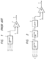
- Fig. 1 is a block diagram of a prior art color-tone correcting apparatus.
- Fig. 2 is a block diagram of a color-tone correcting apparatus according to a first embodiment of this invention.
- Fig. 3 is a time-domain diagram showing the waveforms of various signals in the color-tone correcting apparatus of Fig. 2.
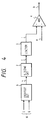
- Fig. 4 is a block diagram of a color-tone correcting apparatus according to a second embodiment of this invention.
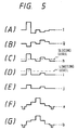
- Fig. 5 is a time-domain diagram showing the waveforms of various signals in the color-tone correcting apparatus of Fig. 4.
- Fig. 6 is a block diagram of a color-tone correcting apparatus according to a third embodiment of this invention.
- Fig. 7 is a time-domain diagram showing the waveforms of various signals in the color-tone correcting apparatus of Fig. 6.
- a prior art color-tone correcting apparatus includes a greatest detector 1 and an adder 4.
- the greatest detector 1 detects the greatest of three color difference signals R-Y, G-Y, and B-Y, and selects the greatest color difference signal and outputs the selected color difference signal "d".
- the greatest color difference signal "d” is used as a color-tone corrective signal or a luminance corrective signal.
- the adder 4 adds an input luminance signal "a” and the greatest color difference signal "d”, combining the signals "a” and "d” into a final luminance signal "b". In other words, the adder 4 corrects the input luminance signal "a” into the final luminance signal "b” in response to the color-tone corrective signal "d".
- the prior art color-tone correcting apparatus of Fig. 1 has the following problems.
- the greatest color difference signal "d” has noise components
- the final luminance signal “b” is also contaminated by the noise components since the final luminance signal “b” results from the addition of the greatest color difference signal "d” and the input luminance signal "a”.
- the greatest color difference signal "d” has a large level
- the final luminance signal "b” tends to be extremely large in level so that the color of the corresponding part of a reproduced image tends to be appreciably lighter than the original color.
- a color-tone correcting apparatus of a first embodiment of this invention includes a greatest detector 1, a slicing circuit 2, a limiter 3, and an adder 4.
- a group "c" of three color difference signals R-Y, B-Y, and C-Y is inputted into the greatest detector 1.
- the greatest detector 1 detects the greatest of the three color difference signals R-Y, G-Y, and B-Y, and selects the greatest color difference signal and outputs the selected color difference signal "d". For example, when the levels of the three color difference signals R-Y, G-Y, and B-Y increase and decrease as shown in the parts (A)-(C) of Fig. 3, the greatest color difference signal "d" varies as shown in the part (D) of Fig. 3.
- the slicing circuit 2 receives the greatest color difference signal "d” from the greatest detector 1.
- the slicing circuit 2 slices the greatest color difference signal "d” with a predetermined slicing level, and thereby converts the greatest color difference signal "d” into a color difference signal "e”.
- the slicing circuit 2 transmits the greatest color difference signal "d” which has a level equal to or greater than the slicing level, but cuts off the greatest color difference signal "d” which has a level below the slicing level. For example, when the level of the greatest color difference signal "d” varies around the slicing level as shown in the part (D) of Fig.
- the output color difference signal "e” from the slicing circuit 2 varies as shown in the part (E) of Fig. 3. In this way, the slicing circuit 2 cuts off the small-level part of the color difference signal "d". Cutting off the small-level part of the color difference signal "d” suppresses or decreases noise components of the color difference signal "d".
- the limiter 3 receives the noise-suppressed color difference signal "e” from the slicing circuit 2.
- the limiter 3 limits the amplitude of the color difference signal “e” to within a predetermined amplitude, and thereby converts the color difference signal "e” into a color difference signal "f".
- the limiter 3 prevents the amplitude of the color difference signal "e” from exceeding a predetermined limiting level.
- the level of the output color difference signal "f” of the limiter 3 is prevented from going excessively great.
- the color difference signal "f” is used as a color-tone corrective signal or a luminance corrective signal.
- the limiter 3 prevents the level of the color-tone corrective signal "f” from going excessively great. Therefore, even when the greatest color difference signal "d” has a large level, the final luminance signal "b” is prevented from going excessively large in level so that the color of the corresponding part of a reproduced image is prevented from being appreciably lighter than the original color.
- This embodiment may be modified as follows.
- a first modification of this embodiment only two of the color difference signals R-Y, G-Y, and B-Y are inputted into the greatest detector 1.
- the slicing circuit 2 has an additional function of removing minus components from the color difference signal "e”.
- the slicing circuit 2 and the limiter 3 are exchanged in position with respect to the arrangement of Fig. 2.
- the input luminance signal "a" has such a polarity that sync components are positive-going, and the adder 4 is replaced by a subtracter.
- a color-tone correcting apparatus of a second embodiment of this invention includes a greatest detector 5, a slicing circuit 2, a limiter 3, and an adder 4.
- a pair “g” of color signals "I” and “Q” is inputted into the greatest detector 5.
- the greatest detector 5 detects the greatest of the color signals "I” and “Q”, and selects the greatest color signal and outputs the selected greatest color signal "h”. For example, when the levels of the color signals "I” and “Q” increase and decrease as shown in the parts (A) and (B) of Fig. 5, the greatest color signal "h” varies as shown in the part (C) of Fig. 5.
- the color subcarrier is modulated with the color signals "I” and "Q”.
- the slicing circuit 2 receives the greatest color signal "h” from the greatest detector 5.
- the slicing circuit 2 slices the greatest color signal "h” with a predetermined slicing level, and thereby converts the greatest color signal "h” into a color signal "i”.
- the slicing circuit 2 transmits the greatest color signal "h” which has a level equal to or greater than the slicing level, but cuts off the greatest color signal "h” which has a level below the slicing level.
- the output color signal "i" from the slicing circuit 2 varies as shown in the part (D) of Fig. 5. In this way, the slicing circuit 2 cuts off the small-level part of the greatest color signal "h”. Cutting off the small-level part of the greatest color signal "h” suppresses or decreases noise components of the greatest color signal "h”.
- the limiter 3 receives the noise-suppressed color signal "i” from the slicing circuit 2.
- the limiter 3 limits the amplitude of the color signal “i” to within a predetermined amplitude, and thereby converts the color signal "i” into a color signal "j".
- the limiter 3 prevents the amplitude of the color signal "i” from exceeding a predetermined limiting level.
- the level of the output color signal "j" of the limiter 3 is prevented from going excessively great.
- the color signal "j” is used as a color-tone corrective signal or a luminance corrective signal.
- the adder 4 receives the amplitude-limited color signal "j" from the limiter 3. In addition, the adder 4 receives an input luminance signal "a". The adder 4 adds the color signal "j" and the input luminance signal "a", combining the signals "j" and “a” into a final luminance signal "b". In other words, the adder 4 corrects the input luminance signal "a” into the final luminance signal "b” in response to the color-tone corrective signal "j". For example, the color signal "j" and the input luminance signal "a” vary as shown in the parts (E) and (F) of Fig. 5, the final luminance signal "b” varies as shown in the part (G) of Fig. 5.
- the limiter 3 prevents the level of the color-tone corrective signal "j" from going excessively great. Therefore, even when the greatest color signal "h” has a large level, the final luminance signal "b" is prevented from going excessively large in level so that the color of the corresponding part of a reproduced image is prevented from being appreciably lighter than the original color.
- This embodiment may be modified as follows.
- the slicing circuit 2 and the limiter 3 are exchanged in position with respect to the arrangement of Fig. 4.
- the input luminance signal "a" has such a polarity that sync components are positive-going, and the adder 4 is replaced by a subtracter.
- a color-tone correcting apparatus of a third embodiment of this invention features that a color-tone component of a video signal is corrected in response to a color signal "I". Since the color signal "I" closely relates to a color which is generally sensed by human eyes at a highest sensitivity, the use of the color signal "I” enables an effective color-tone correction.
- a color-tone correcting apparatus of a third embodiment of this invention includes a slicing circuit 2, a limiter 3, and an adder 4.
- a color signal "I” is inputted into the slicing circuit 2.
- the slicing circuit 2 slices the color signal "I” with a predetermined slicing level, and thereby converts the color signal “I” into a color signal "k”. Specifically, the slicing circuit 2 transmits the color signal "I” which has a level equal to or greater than the slicing level, but cuts off the color signal "I” which has a level below the slicing level. For example, when the level of the color signal "I” varies around the slicing level as shown in the part (A) of Fig. 7, the output color signal "k” from the slicing circuit 2 varies as shown in the part (B) of Fig. 7. In this way, the slicing circuit 2 cuts off the small-level part of the color signal "I”. Cutting off the small-level part of the color signal "I” suppresses or decreases noise components of the color signal "I”.
- the limiter 3 receives the noise-suppressed color signal "k” from the slicing circuit 2.
- the limiter 3 limits the amplitude of the color signal “k” to within a predetermined amplitude, and thereby converts the color signal "k” into a color signal "m”.
- the limiter 3 prevents the amplitude of the color signal "k” from exceeding a predetermined limiting level.
- the level of the output color signal "m” of the limiter 3 is prevented from going excessively great.
- the color signal "m” is used as a color-tone corrective signal or a luminance corrective signal.
- the adder 4 receives the amplitude-limited color signal "m” from the limiter 3. In addition, the adder 4 receives an input luminance signal "a". The adder 4 adds the color signal "m” and the input luminance signal "a", combining the signals "m” and “a” into a final luminance signal "b". In other words, the adder 4 corrects the input luminance signal "a” into the final luminance signal "b” in response to the color-tone corrective signal "m”. For example, the color signal "m” and the input luminance signal "a” vary as shown in the parts (C) and (D) of Fig. 7, the final luminance signal "b” varies as shown in the part (E) of Fig. 7.
- the limiter 3 prevents the level of the color-tone corrective signal "m” from going excessively great. Therefore, even when the color signal "I” has a large level, the final luminance signal "b” is prevented from going excessively large in level so that the color of the corresponding part of a reproduced image is prevented from being appreciably lighter than the original color.
- This embodiment may be modified as follows.
- the slicing circuit 2 and the limiter 3 are exchanged in position with respect to the arrangement of Fig. 6.
- the input luminance signal "a" has such a polarity that sync components are positive-going, and the adder 4 is replaced by a subtracter.
Landscapes
- Engineering & Computer Science (AREA)
- Multimedia (AREA)
- Signal Processing (AREA)
- Processing Of Color Television Signals (AREA)
- Picture Signal Circuits (AREA)
Description
- This invention relates to an apparatus for correcting a color-tone component of a video signal. This invention also relates to a television receiver including such a color-tone correcting apparatus.
- In the field of color television receivers, there are various apparatuses for correcting a color-tone component of a video signal to clarify a reproduced color image.
- Document US-A-4 812 905 discloses a color-tone correcting apparatus comprising: means for detecting a greatest color-representing component video signal of input component video signals, and outputting said detected greatest color-representing component video signal.
- Furthermore, from document JP-A-63 318 888 a color-tone correcting apparatus is known, comprising limiting means for limiting a level of a color-representing component video signal and means for adding a luminance representing component video signal and an output signal of said limiting means.
- As will be explained later, a prior art color-tone correcting apparatus has some problem.
- It is an object of this invention to provide an improved apparatus for correcting a color tone of a video signal.
- It is another object of this invention to provide a television receiver including such a color-tone correcting apparatus.
- According to the invention this object is accomplished by a color-tone correcting apparatus comprising: first means for detecting a greatest color-representing component video signal of input component video signals, and outputting said detected greatest color-representing component video signal; said color-tone correcting apparatus being characterized by second means for removing small-level components from the output signal of said first means, and limiting an amplitude of the output signal of said first means to within a predetermined amplitude; and third means for adding an output signal of said second means and an input luminance signal.
- Further objects, advantages and features of the invention will become apparent from a common consideration of the description in combination with the accompanying drawings, of which:
- Fig. 1 is a block diagram of a prior art color-tone correcting apparatus.
- Fig. 2 is a block diagram of a color-tone correcting apparatus according to a first embodiment of this invention.
- Fig. 3 is a time-domain diagram showing the waveforms of various signals in the color-tone correcting apparatus of Fig. 2.
- Fig. 4 is a block diagram of a color-tone correcting apparatus according to a second embodiment of this invention.
- Fig. 5 is a time-domain diagram showing the waveforms of various signals in the color-tone correcting apparatus of Fig. 4.
- Fig. 6 is a block diagram of a color-tone correcting apparatus according to a third embodiment of this invention.
- Fig. 7 is a time-domain diagram showing the waveforms of various signals in the color-tone correcting apparatus of Fig. 6.
- As shown in Fig. 1, a prior art color-tone correcting apparatus includes a
greatest detector 1 and anadder 4. Thegreatest detector 1 detects the greatest of three color difference signals R-Y, G-Y, and B-Y, and selects the greatest color difference signal and outputs the selected color difference signal "d". As will be made clear later, the greatest color difference signal "d" is used as a color-tone corrective signal or a luminance corrective signal. Theadder 4 adds an input luminance signal "a" and the greatest color difference signal "d", combining the signals "a" and "d" into a final luminance signal "b". In other words, theadder 4 corrects the input luminance signal "a" into the final luminance signal "b" in response to the color-tone corrective signal "d". - The prior art color-tone correcting apparatus of Fig. 1 has the following problems. When the greatest color difference signal "d" has noise components, the final luminance signal "b" is also contaminated by the noise components since the final luminance signal "b" results from the addition of the greatest color difference signal "d" and the input luminance signal "a". When the greatest color difference signal "d" has a large level, the final luminance signal "b" tends to be extremely large in level so that the color of the corresponding part of a reproduced image tends to be appreciably lighter than the original color.
- With reference to Fig. 2, a color-tone correcting apparatus of a first embodiment of this invention includes a
greatest detector 1, aslicing circuit 2, alimiter 3, and anadder 4. - A group "c" of three color difference signals R-Y, B-Y, and C-Y is inputted into the
greatest detector 1. Thegreatest detector 1 detects the greatest of the three color difference signals R-Y, G-Y, and B-Y, and selects the greatest color difference signal and outputs the selected color difference signal "d". For example, when the levels of the three color difference signals R-Y, G-Y, and B-Y increase and decrease as shown in the parts (A)-(C) of Fig. 3, the greatest color difference signal "d" varies as shown in the part (D) of Fig. 3. - The
slicing circuit 2 receives the greatest color difference signal "d" from thegreatest detector 1. Theslicing circuit 2 slices the greatest color difference signal "d" with a predetermined slicing level, and thereby converts the greatest color difference signal "d" into a color difference signal "e". Specifically, theslicing circuit 2 transmits the greatest color difference signal "d" which has a level equal to or greater than the slicing level, but cuts off the greatest color difference signal "d" which has a level below the slicing level. For example, when the level of the greatest color difference signal "d" varies around the slicing level as shown in the part (D) of Fig. 3, the output color difference signal "e" from theslicing circuit 2 varies as shown in the part (E) of Fig. 3. In this way, theslicing circuit 2 cuts off the small-level part of the color difference signal "d". Cutting off the small-level part of the color difference signal "d" suppresses or decreases noise components of the color difference signal "d". - The
limiter 3 receives the noise-suppressed color difference signal "e" from theslicing circuit 2. Thelimiter 3 limits the amplitude of the color difference signal "e" to within a predetermined amplitude, and thereby converts the color difference signal "e" into a color difference signal "f". Specifically, thelimiter 3 prevents the amplitude of the color difference signal "e" from exceeding a predetermined limiting level. As a result, the level of the output color difference signal "f" of thelimiter 3 is prevented from going excessively great. For example, when the color difference signal "e" varies around the limiting level as shown in the part (E) of Fig. 3, the output color difference signal "f" from thelimiter 3 varies as shown in the part (F) of Fig. 3. As will be made clear later, the color difference signal "f" is used as a color-tone corrective signal or a luminance corrective signal. - The
adder 4 receives the amplitude-limited color difference signal "f" from thelimiter 3. In addition, theadder 4 receives an input luminance signal "a". Theadder 4 adds the color difference signal "f" and the input luminance signal "a", combining the signals "f" and "a" into a final luminance signal "b". In other words, theadder 4 corrects the input luminance signal "a" into the final luminance signal "b" in response to the color-tone corrective signal "f". For example, the color difference signal "f" and the input luminance signal "a" vary as shown in the parts (F) and (G) of Fig. 3, the final luminance signal "b" varies as shown in the part (H) of Fig. 3. - When the greatest color difference signal "d" is large in level, the
limiter 3 prevents the level of the color-tone corrective signal "f" from going excessively great. Therefore, even when the greatest color difference signal "d" has a large level, the final luminance signal "b" is prevented from going excessively large in level so that the color of the corresponding part of a reproduced image is prevented from being appreciably lighter than the original color. - This embodiment may be modified as follows. In a first modification of this embodiment, only two of the color difference signals R-Y, G-Y, and B-Y are inputted into the
greatest detector 1. For example, only the color difference signals R-Y and B-Y are inputted into thegreatest detector 1. In this modification, theslicing circuit 2 has an additional function of removing minus components from the color difference signal "e". In a second modification of this embodiment, theslicing circuit 2 and thelimiter 3 are exchanged in position with respect to the arrangement of Fig. 2. In a third modification of this embodiment, the input luminance signal "a" has such a polarity that sync components are positive-going, and theadder 4 is replaced by a subtracter. - With reference to Fig. 4, a color-tone correcting apparatus of a second embodiment of this invention includes a
greatest detector 5, aslicing circuit 2, alimiter 3, and anadder 4. - A pair "g" of color signals "I" and "Q" is inputted into the
greatest detector 5. Thegreatest detector 5 detects the greatest of the color signals "I" and "Q", and selects the greatest color signal and outputs the selected greatest color signal "h". For example, when the levels of the color signals "I" and "Q" increase and decrease as shown in the parts (A) and (B) of Fig. 5, the greatest color signal "h" varies as shown in the part (C) of Fig. 5. - In the NTSC system, the color signals "I" and "Q" have the following relations with the color difference signals R-Y and B-Y.


- The
slicing circuit 2 receives the greatest color signal "h" from thegreatest detector 5. Theslicing circuit 2 slices the greatest color signal "h" with a predetermined slicing level, and thereby converts the greatest color signal "h" into a color signal "i". Specifically, the slicingcircuit 2 transmits the greatest color signal "h" which has a level equal to or greater than the slicing level, but cuts off the greatest color signal "h" which has a level below the slicing level. For example, when the level of the greatest color signal "h" varies around the slicing level as shown in the part (C) of Fig. 5, the output color signal "i" from the slicingcircuit 2 varies as shown in the part (D) of Fig. 5. In this way, the slicingcircuit 2 cuts off the small-level part of the greatest color signal "h". Cutting off the small-level part of the greatest color signal "h" suppresses or decreases noise components of the greatest color signal "h". - The
limiter 3 receives the noise-suppressed color signal "i" from the slicingcircuit 2. Thelimiter 3 limits the amplitude of the color signal "i" to within a predetermined amplitude, and thereby converts the color signal "i" into a color signal "j". Specifically, thelimiter 3 prevents the amplitude of the color signal "i" from exceeding a predetermined limiting level. As a result, the level of the output color signal "j" of thelimiter 3 is prevented from going excessively great. For example, when the color signal "i" varies around the limiting level as shown in the part (D) of Fig. 5, the output color signal "j" from thelimiter 3 varies as shown in the part (E) of Fig. 5. As will be made clear later, the color signal "j" is used as a color-tone corrective signal or a luminance corrective signal. - The
adder 4 receives the amplitude-limited color signal "j" from thelimiter 3. In addition, theadder 4 receives an input luminance signal "a". Theadder 4 adds the color signal "j" and the input luminance signal "a", combining the signals "j" and "a" into a final luminance signal "b". In other words, theadder 4 corrects the input luminance signal "a" into the final luminance signal "b" in response to the color-tone corrective signal "j". For example, the color signal "j" and the input luminance signal "a" vary as shown in the parts (E) and (F) of Fig. 5, the final luminance signal "b" varies as shown in the part (G) of Fig. 5. - When the greatest color signal "h" is large in level, the
limiter 3 prevents the level of the color-tone corrective signal "j" from going excessively great. Therefore, even when the greatest color signal "h" has a large level, the final luminance signal "b" is prevented from going excessively large in level so that the color of the corresponding part of a reproduced image is prevented from being appreciably lighter than the original color. - This embodiment may be modified as follows. In a first modification of this embodiment, the slicing
circuit 2 and thelimiter 3 are exchanged in position with respect to the arrangement of Fig. 4. In a second modification of this embodiment, the input luminance signal "a" has such a polarity that sync components are positive-going, and theadder 4 is replaced by a subtracter. - A color-tone correcting apparatus of a third embodiment of this invention features that a color-tone component of a video signal is corrected in response to a color signal "I". Since the color signal "I" closely relates to a color which is generally sensed by human eyes at a highest sensitivity, the use of the color signal "I" enables an effective color-tone correction.
- With reference to Fig. 6, a color-tone correcting apparatus of a third embodiment of this invention includes a
slicing circuit 2, alimiter 3, and anadder 4. - A color signal "I" is inputted into the
slicing circuit 2. Theslicing circuit 2 slices the color signal "I" with a predetermined slicing level, and thereby converts the color signal "I" into a color signal "k". Specifically, the slicingcircuit 2 transmits the color signal "I" which has a level equal to or greater than the slicing level, but cuts off the color signal "I" which has a level below the slicing level. For example, when the level of the color signal "I" varies around the slicing level as shown in the part (A) of Fig. 7, the output color signal "k" from the slicingcircuit 2 varies as shown in the part (B) of Fig. 7. In this way, the slicingcircuit 2 cuts off the small-level part of the color signal "I". Cutting off the small-level part of the color signal "I" suppresses or decreases noise components of the color signal "I". - The
limiter 3 receives the noise-suppressed color signal "k" from the slicingcircuit 2. Thelimiter 3 limits the amplitude of the color signal "k" to within a predetermined amplitude, and thereby converts the color signal "k" into a color signal "m". Specifically, thelimiter 3 prevents the amplitude of the color signal "k" from exceeding a predetermined limiting level. As a result, the level of the output color signal "m" of thelimiter 3 is prevented from going excessively great. For example, when the color signal "k" varies around the limiting level as shown in the part (B) of Fig. 7, the output color signal "m" from thelimiter 3 varies as shown in the part (C) of Fig. 7. As will be made clear later, the color signal "m" is used as a color-tone corrective signal or a luminance corrective signal. - The
adder 4 receives the amplitude-limited color signal "m" from thelimiter 3. In addition, theadder 4 receives an input luminance signal "a". Theadder 4 adds the color signal "m" and the input luminance signal "a", combining the signals "m" and "a" into a final luminance signal "b". In other words, theadder 4 corrects the input luminance signal "a" into the final luminance signal "b" in response to the color-tone corrective signal "m". For example, the color signal "m" and the input luminance signal "a" vary as shown in the parts (C) and (D) of Fig. 7, the final luminance signal "b" varies as shown in the part (E) of Fig. 7. - When the color signal "I" is large in level, the
limiter 3 prevents the level of the color-tone corrective signal "m" from going excessively great. Therefore, even when the color signal "I" has a large level, the final luminance signal "b" is prevented from going excessively large in level so that the color of the corresponding part of a reproduced image is prevented from being appreciably lighter than the original color. - This embodiment may be modified as follows. In a first modification of this embodiment, the slicing
circuit 2 and thelimiter 3 are exchanged in position with respect to the arrangement of Fig. 6. In a second modification of this embodiment, the input luminance signal "a" has such a polarity that sync components are positive-going, and theadder 4 is replaced by a subtracter.
Claims (9)
- A color-tone correcting apparatus comprising:
first means (1; 5) for detecting a greatest color-representing component video signal (d; h) of input component video signals (R-Y, G-Y, B-Y; I, Q), and outputting said detected greatest color-representing component video signal (d; h);
said color-tone correcting apparatus being characterized bysecond means (2, 3) for removing small-level components from the output signal (d; h) of said first means (1; 5), and limiting an amplitude of the output signal (d; h) of said first means (1; 5) to within a predetermined amplitude; andthird means (4) for adding an output signal (f; j) of said second means (2, 3) and an input luminance signal (a). - A color-tone correcting apparatus according to claim 1,
characterized in that
said input component video signals (R-Y, G-Y, B-Y) comprise color difference signals. - A color-tone correcting apparatus according to claim 2,
characterized in that
said color difference signals comprise a color difference signal R-Y, a color difference signal B-Y, and a color difference signal G-Y. - A color-tone correcting apparatus according to claim 2,
characterized in that
said color difference signals comprise a color difference signal R-Y, and a color difference signal B-Y. - A color-tone correcting apparatus according to claim 1,
characterized in that
said input component video signals (I, Q) comprise a color signal "I" and a color signal "Q". - A color-tone correcting apparatus according to claim 1,
characterized in that
said input component video signals (I) comprise a color signal "I". - A color-tone correcting apparatus according to claim 1,
characterized in that
said first means (5) detects the greatest color-representing component video signal (h) of a color signal "I" and a color signal "Q". - A color-tone correcting apparatus according to claim 1,
characterized in that
said first means (1) detects the greatest color-representing component video signals (d) from at least two of a color difference signal R-Y, a color difference signal B-Y, and a color difference signal G-Y. - A television receiver comprising a color-tone correcting apparatus according to any of the preceding claims 1 to 8.
Applications Claiming Priority (2)
| Application Number | Priority Date | Filing Date | Title |
|---|---|---|---|
| JP2148286A JP2775997B2 (en) | 1990-06-05 | 1990-06-05 | Video signal gradation correction device and television receiver |
| JP148286/90 | 1990-06-05 |
Publications (3)
| Publication Number | Publication Date |
|---|---|
| EP0460596A2 EP0460596A2 (en) | 1991-12-11 |
| EP0460596A3 EP0460596A3 (en) | 1993-04-07 |
| EP0460596B1 true EP0460596B1 (en) | 1996-09-04 |
Family
ID=15449375
Family Applications (1)
| Application Number | Title | Priority Date | Filing Date |
|---|---|---|---|
| EP91109095A Expired - Lifetime EP0460596B1 (en) | 1990-06-05 | 1991-06-04 | Apparatus for correcting a color tone of a video signal |
Country Status (7)
| Country | Link |
|---|---|
| US (1) | US5255079A (en) |
| EP (1) | EP0460596B1 (en) |
| JP (1) | JP2775997B2 (en) |
| KR (1) | KR950005066B1 (en) |
| CA (1) | CA2043856C (en) |
| DE (1) | DE69121783T2 (en) |
| MY (1) | MY110231A (en) |
Families Citing this family (12)
| Publication number | Priority date | Publication date | Assignee | Title |
|---|---|---|---|---|
| JP3208814B2 (en) * | 1992-01-09 | 2001-09-17 | 松下電器産業株式会社 | Video signal correction device |
| US7382142B2 (en) | 2000-05-23 | 2008-06-03 | Nanonexus, Inc. | High density interconnect system having rapid fabrication cycle |
| US7247035B2 (en) | 2000-06-20 | 2007-07-24 | Nanonexus, Inc. | Enhanced stress metal spring contactor |
| US7349223B2 (en) | 2000-05-23 | 2008-03-25 | Nanonexus, Inc. | Enhanced compliant probe card systems having improved planarity |
| US6812718B1 (en) | 1999-05-27 | 2004-11-02 | Nanonexus, Inc. | Massively parallel interface for electronic circuits |
| US6799976B1 (en) | 1999-07-28 | 2004-10-05 | Nanonexus, Inc. | Construction structures and manufacturing processes for integrated circuit wafer probe card assemblies |
| US7952373B2 (en) | 2000-05-23 | 2011-05-31 | Verigy (Singapore) Pte. Ltd. | Construction structures and manufacturing processes for integrated circuit wafer probe card assemblies |
| US7579848B2 (en) | 2000-05-23 | 2009-08-25 | Nanonexus, Inc. | High density interconnect system for IC packages and interconnect assemblies |
| KR100402838B1 (en) * | 2001-05-10 | 2003-10-22 | 주식회사 효성 | Polyester multifilament yarns |
| US20060104537A1 (en) * | 2004-11-12 | 2006-05-18 | Sozotek, Inc. | System and method for image enhancement |
| KR102544691B1 (en) * | 2020-07-01 | 2023-06-15 | 코오롱인더스트리 주식회사 | Recycled fiber, Composite for vehicle and method for preparing the same |
| KR102544692B1 (en) * | 2020-07-01 | 2023-06-15 | 코오롱인더스트리 주식회사 | Recycled fiber, Composite for vehicle and method for preparing the same |
Family Cites Families (10)
| Publication number | Priority date | Publication date | Assignee | Title |
|---|---|---|---|---|
| JPS588194B2 (en) * | 1977-12-12 | 1983-02-15 | 日本放送協会 | Color television signal processing equipment |
| JPS5623086A (en) * | 1979-08-02 | 1981-03-04 | Hitachi Ltd | Picture quality improving circuit of color television receiver |
| US4337479A (en) * | 1979-09-13 | 1982-06-29 | Matsushita Electric Industrial Co., Ltd. | Color resolution compensator |
| DE2937958C2 (en) * | 1979-09-20 | 1982-03-25 | Robert Bosch Gmbh, 7000 Stuttgart | Process for horizontal and vertical contour correction |
| JPS6033358A (en) * | 1983-08-04 | 1985-02-20 | Hitachi Chem Co Ltd | Electroless copper plating liquid |
| US4558352A (en) * | 1983-11-28 | 1985-12-10 | Rca Corporation | Sampled data vertical detail signal processor |
| JPS62239670A (en) * | 1986-04-11 | 1987-10-20 | Ikegami Tsushinki Co Ltd | Contour emphasizing device |
| JPS63318888A (en) * | 1987-06-22 | 1988-12-27 | Toshiba Corp | Chrominance signal correction circuit |
| US4812905A (en) * | 1988-01-15 | 1989-03-14 | Rossi John P | System for compensating for the violation of the constant luminance principle in color television systems |
| JP2583325B2 (en) * | 1989-12-26 | 1997-02-19 | 池上通信機株式会社 | Gradation correction circuit |
-
1990
- 1990-06-05 JP JP2148286A patent/JP2775997B2/en not_active Expired - Fee Related
-
1991
- 1991-05-30 US US07/707,509 patent/US5255079A/en not_active Expired - Lifetime
- 1991-05-31 MY MYPI91000966A patent/MY110231A/en unknown
- 1991-06-04 CA CA002043856A patent/CA2043856C/en not_active Expired - Fee Related
- 1991-06-04 EP EP91109095A patent/EP0460596B1/en not_active Expired - Lifetime
- 1991-06-04 DE DE69121783T patent/DE69121783T2/en not_active Expired - Fee Related
- 1991-06-04 KR KR1019910009205A patent/KR950005066B1/en not_active IP Right Cessation
Non-Patent Citations (1)
| Title |
|---|
| Patent Abstracts of Japan, Vol.13, No 166, & JP-A-63 318 888 * |
Also Published As
| Publication number | Publication date |
|---|---|
| DE69121783T2 (en) | 1997-02-06 |
| KR950005066B1 (en) | 1995-05-17 |
| MY110231A (en) | 1998-03-31 |
| CA2043856A1 (en) | 1991-12-06 |
| JPH0440192A (en) | 1992-02-10 |
| CA2043856C (en) | 1995-10-03 |
| JP2775997B2 (en) | 1998-07-16 |
| EP0460596A2 (en) | 1991-12-11 |
| DE69121783D1 (en) | 1996-10-10 |
| EP0460596A3 (en) | 1993-04-07 |
| US5255079A (en) | 1993-10-19 |
| KR920001930A (en) | 1992-01-30 |
Similar Documents
| Publication | Publication Date | Title |
|---|---|---|
| EP0460596B1 (en) | Apparatus for correcting a color tone of a video signal | |
| US5012329A (en) | Method of encoded video decoding | |
| US20020037101A1 (en) | Image processing apparatus, image processing method and computer program product for correcting image obtained by shooting subject | |
| KR960016851B1 (en) | Luminance signal forming circuit | |
| EP0551189B1 (en) | Video signal correction system | |
| EP0460595B1 (en) | Apparatus for correcting a black level of a video signal | |
| EP0705516B1 (en) | High luminance color suppression circuit | |
| US4480266A (en) | Method and apparatus for preventing generation of false color signals in color television cameras | |
| US4686561A (en) | Vertical detail information restoration circuit | |
| US5150203A (en) | Variable chrominance filtering for encoding television signals | |
| GB2203011A (en) | Transmitting television signals | |
| US5561473A (en) | Contour correction signal generating circuit | |
| US4862252A (en) | Y/C separator circuit for separating luminance and chrominance signals conditioned on an ac luminance component | |
| US4907073A (en) | Adaptive device for separating luminance signal and color signal | |
| US7012719B1 (en) | Sign sensitive aperture correction system and method | |
| US5103296A (en) | Color television system having adaptive filters in the transmitter encoder and in the receiver decoder | |
| EP0130294B1 (en) | Selective primary colour enhancement apparatus for an image pick-up device | |
| US6243144B1 (en) | Adaptive false color video filter and method | |
| KR100190040B1 (en) | Fake color signal suppression apparatus | |
| EP0587224B1 (en) | Extended television signal receiver | |
| US7139037B1 (en) | Circle correction in digital low-pass filter | |
| KR920007493Y1 (en) | Hue control circuit of digital television | |
| KR100219603B1 (en) | The color tv receiver to output with frame screen compensating by color characteristic to printing | |
| JP2005286694A (en) | Dot disturbance reduction circuit, display | |
| JPH05122716A (en) | Disturbance elimination circuit |
Legal Events
| Date | Code | Title | Description |
|---|---|---|---|
| PUAI | Public reference made under article 153(3) epc to a published international application that has entered the european phase |
Free format text: ORIGINAL CODE: 0009012 |
|
| 17P | Request for examination filed |
Effective date: 19910704 |
|
| AK | Designated contracting states |
Kind code of ref document: A2 Designated state(s): DE GB |
|
| PUAL | Search report despatched |
Free format text: ORIGINAL CODE: 0009013 |
|
| AK | Designated contracting states |
Kind code of ref document: A3 Designated state(s): DE GB |
|
| 17Q | First examination report despatched |
Effective date: 19931027 |
|
| GRAH | Despatch of communication of intention to grant a patent |
Free format text: ORIGINAL CODE: EPIDOS IGRA |
|
| GRAA | (expected) grant |
Free format text: ORIGINAL CODE: 0009210 |
|
| AK | Designated contracting states |
Kind code of ref document: B1 Designated state(s): DE GB |
|
| REF | Corresponds to: |
Ref document number: 69121783 Country of ref document: DE Date of ref document: 19961010 |
|
| PLBE | No opposition filed within time limit |
Free format text: ORIGINAL CODE: 0009261 |
|
| STAA | Information on the status of an ep patent application or granted ep patent |
Free format text: STATUS: NO OPPOSITION FILED WITHIN TIME LIMIT |
|
| 26N | No opposition filed | ||
| REG | Reference to a national code |
Ref country code: GB Ref legal event code: IF02 |
|
| PGFP | Annual fee paid to national office [announced via postgrant information from national office to epo] |
Ref country code: GB Payment date: 20050601 Year of fee payment: 15 |
|
| PGFP | Annual fee paid to national office [announced via postgrant information from national office to epo] |
Ref country code: DE Payment date: 20050602 Year of fee payment: 15 |
|
| PG25 | Lapsed in a contracting state [announced via postgrant information from national office to epo] |
Ref country code: GB Free format text: LAPSE BECAUSE OF NON-PAYMENT OF DUE FEES Effective date: 20060604 |
|
| PG25 | Lapsed in a contracting state [announced via postgrant information from national office to epo] |
Ref country code: DE Free format text: LAPSE BECAUSE OF NON-PAYMENT OF DUE FEES Effective date: 20070103 |
|
| GBPC | Gb: european patent ceased through non-payment of renewal fee |
Effective date: 20060604 |