EP0456224B1 - Color cathode ray tube apparatus - Google Patents
Color cathode ray tube apparatus Download PDFInfo
- Publication number
- EP0456224B1 EP0456224B1 EP19910107505 EP91107505A EP0456224B1 EP 0456224 B1 EP0456224 B1 EP 0456224B1 EP 19910107505 EP19910107505 EP 19910107505 EP 91107505 A EP91107505 A EP 91107505A EP 0456224 B1 EP0456224 B1 EP 0456224B1
- Authority
- EP
- European Patent Office
- Prior art keywords
- electron
- permanent magnet
- deflection device
- axis
- magnetic
- Prior art date
- Legal status (The legal status is an assumption and is not a legal conclusion. Google has not performed a legal analysis and makes no representation as to the accuracy of the status listed.)
- Expired - Lifetime
Links
Images


Classifications
-
- H—ELECTRICITY
- H01—ELECTRIC ELEMENTS
- H01J—ELECTRIC DISCHARGE TUBES OR DISCHARGE LAMPS
- H01J29/00—Details of cathode-ray tubes or of electron-beam tubes of the types covered by group H01J31/00
- H01J29/46—Arrangements of electrodes and associated parts for generating or controlling the ray or beam, e.g. electron-optical arrangement
- H01J29/56—Arrangements for controlling cross-section of ray or beam; Arrangements for correcting aberration of beam, e.g. due to lenses
- H01J29/566—Arrangements for controlling cross-section of ray or beam; Arrangements for correcting aberration of beam, e.g. due to lenses for correcting aberration
-
- H—ELECTRICITY
- H01—ELECTRIC ELEMENTS
- H01J—ELECTRIC DISCHARGE TUBES OR DISCHARGE LAMPS
- H01J29/00—Details of cathode-ray tubes or of electron-beam tubes of the types covered by group H01J31/00
- H01J29/46—Arrangements of electrodes and associated parts for generating or controlling the ray or beam, e.g. electron-optical arrangement
- H01J29/70—Arrangements for deflecting ray or beam
- H01J29/701—Systems for correcting deviation or convergence of a plurality of beams by means of magnetic fields at least
- H01J29/707—Arrangements intimately associated with parts of the gun and co-operating with external magnetic excitation devices
Definitions
- the present invention relates to a deflection device for a color cathode ray tube apparatus featuring improved focus characteristic by effect of minimized deflection aberration.
- a color cathode ray tube apparatus of shadow mask type comprises a panel section having a generally rectangular face plate and a skirt extending from a lateral edge of the face plate, a funnel section connected to the panel section, and a neck section continuously formed with the funnel section.
- the interior of the cathode ray tube is maintained in a vacuum state by the panel section, the funnel section and the neck section.
- an electron gun assembly which generates three electron beams (R), (G) and (B).
- R electron beams
- G electron beams
- B electron beams
- a deflection device At the outer lateral side of the portion of the apparatus between the funnel section and the neck section is disposed a deflection device for generating magnetic fields which deflect electron beams vertically and horizontally.
- a phosphor screen is formed on the inner face of the face plate of the panel.
- a generally rectangular shadow mask is opposed to the face plate at a predetermined spacing.
- the shadow mask is made of a thin metal plate and provided with a lot
- the deflection device for use in the color cathode ray tube apparatus of shadow mask type has a horizontal deflection coil and a vertical deflection coil which produce magnetic fields for respectively horizontally and vertically deflecting the three electron beams (R), (G), (B) emitted from the electron gun assembly. After being deflected by the horizontal and vertical deflection coils, the three electron beams (R), (G) and (B) are converged towards the corresponding slit. The electron beams (R), (G) and (B) converged at the vicinity of the slit are landed on the phosphor screen which has three kinds of phosphor stripes alternately arranged to each other.
- the three electron beams (R), (G) and (B) pass the slit and are incident on the phosphor screen, thereby the red light, green light and blue light are emitted from the phosphor stripes. In other words, the three beams are landed on the corresponding phosphor stripes which emit the red, green and blue light.
- the electron beam (G) which causes green light to be emitted is radiated from the electron gun so as to coincide with the tube axis.
- the electron beams (B) and (R) which cause blue light and red light to be emitted, respectively, are radiated, with the electron beam (G) disposed therebetween.
- the color cathode ray tube apparatus which employs the characteristic of the inline type electron gun to produce specific non-uniform magnetic fields by means of deflection yokes, is a self-convergence type color cathode ray tube apparatus.
- a horizontal deflection magnetic field of mainly pincushion type and a vertical deflection magnetic field of mainly barrel type are applied.
- the impression of these magnetic fields enables the three electron beams radiated on the same horizontal plane to be converged on the phosphor screen.
- Sho 57-45748 discloses another apparatus in which an auxiliary coil is provided at the side of the electron gun of a deflection device and is adapted to render an electrical current to flow in synchronism with the deflection current flowing in a vertical deflection coil, thereby generating a strong pincushion type magnetic field.
- Fig. 1 designates this condition. If these three electron beams where subject to deflection by effect of uniform magnetic filed, the shape of beam spots of these three electron beams remains circular all over the fluorescent surface. On the other hand, as shown in Fig.
- the beam-spot shapes 13b and 13r of a pair of side beams B and R among those three electron beams distort themselves into an elliptical form which extends itself in the about 90°-inclined direction to intersect with each other.
- the shape of beam spot of the center beams G among those three electron beams distorts itself into horizontally extended elliptical form on receipt of the Lorentz's force.
- focus characteristics in the periphery of the fluorescent surface is significantly degraded.
- manufacturers are obliged to design the color cathode ray tube apparatus to level off the focus characteristic of the whole fluorescent surface even though satisfactory focus characteristic may be sacrificed in the center region of the fluorescent surface.
- auxiliary coil contains a coil wound on a magnetic member in order to allow current to flow through the coil, considering the nature of being an auxiliary element, it is by no means economical to use.
- impedance of the deflection device is often variable. If the impedance of the deflection device were changed, then, current flowing through the deflection coil fluctuates. As a result, in order to offset influence of the auxiliary coil affecting the deflection device, it is essential for the TV manufacturers to change specification of the auxiliary coil in correspondence with the impedance of the deflection coil, and thus, the color cathode ray tube using the above auxiliary coil involves poor compatibility with the mass production.
- Those permanent magnets 10a and 10b are disposed on the axis X orthogonally intersecting the aligned direction of three electron beams, where these permanent magnets 10a and 10b respectively generate pin-cushion type magnetic filed.
- the pin-cushion type magnetic field generates specific Lorentz's force which compensates for the deformation of the beam spot shape of three electron beams caused by the other Lorentz's force of the barrel-type deflection magnetic filed generated by the second deflection coil.
- the other pair of permanent magnetic 10c and 10d are respectively disposed on the axis X which is in parallel with the aligned direction of these three electron beams, where these permanent magnets 10c and 10d respectively generate specific Lorentz's force inverse from the other Lorentz's force of the barrel-type deflection magnetic filed generated by the second deflection coil.
- this inverse Lorentz's force independent of influence of the barrel-type deflection magnetic filed generated by the second deflection coil 4, a pair of side beams B and R can be prevented from deforming themseleves in the oblique direction.
- Prior art document EP-A-59 004 discloses a picture display device having a display tube and a self-converging system of deflection coils. In this display device, focusing is substantially independent of the deflection by the system of the deflection coils and takes place by means of two quadrupole lenses and a focusing lens. Also an eight-pole magnetic lens can be used.
- prior art document EP-A-53 853 describes a cathode-ray tube and a deflection unit.
- this cathode-ray tube an eight-pole magnetic field is generated in a region closer to the screen than the center of the deflection yoke.
- the object of the invention is to fully solve the technical problems as mentioned above by providing a novel deflection device capable of securely providing satisfactory focus characteristics throughout the whole screen surface without degrading the convergence characteristics at all.
- the present invention provides a deflection device as specified in claim 1 or 8.
- the deflection device embodied by the invention characteristically incorporates a single unit of eight-pole permanent magnet disc capable of precisely positioning a plurality of magnetic poles between the end of the deflection device on the side of the electron gun and the electron gun itself.
- Fig. 6 is a sectional view of the color cathode ray tube apparatus according to the first embodiment of the invention.
- the color cathode ray tube apparatus 50 incorporates the following; a panel section 52 which is internally provided with a substantially rectangular face plate 54 and a skirt 51 which extends itself from the side edge of the face plate 54, a funnel section 58 which is connected to the panel section 52, and an envelope member 61 which envelopes a neck section 60 connected to the funnel section 58.
- the panel section 52, the funnel section 58, and the neck section 60 conjunctionally hold the interior of the color cathode ray tube in perfect vacuum.
- the neck section 60 incorporates an electron-gun assembly 62 which generates three electron beams R, G, and B.
- a deflection device 64 is provided with a pair of horizontal deflection coils 80 generating specific magnetic field which deflects those three electron beams R, G, and B in the horizontal direction and a pair of vertical deflection coils 82 generating specific magnetic field which deflects those three electron beams R, G, and B in the vertical direction.
- the deflection device 64 is secured to the external surface of the funnel section 58 and the neck section 60.
- a ring-shaped permanent magnet 70 incorporating eight magnetic poles is secured to the deflection device 64 at the position close to the electron-gun assembly 62.
- a phosphor screen 74 is provided on the inner surface of the face plate 54 of the panel section 52.
- Shadow mask 76 of substantially rectangular shape is disposed inside of the color cathode ray tube in opposition from the phosphor screen 74 at the predetermined intervals.
- the shadow mask 76 is made of extremely thin metallic sheets and provided with a large number of through holes.
- a mask frame 78 is provided in the periphery of these shadow masks 76 in order to support them.
- the mask frame 78 is secured to the panel section 52 by means of a plurality of elastic supporters (not shown).
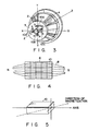
- Fig. 7 is an enlarged perspective view of the deflection device 64, which incorporates a pair of saddle-type horizontal deflection coils 80 symmetrically being disposed in the vertical (Y-axial) direction of a separator 83 and a pair of troidal-type vertical deflection coils 82 wound on a core 84, respectively. Synchronized currents each having a different value compatible with those deflection coils 80 and 83 are respectively delivered to passive circuits (not shown) which incorporates those elements like resistors and line concentrators.
- the ring-shaped permanent magnet 70 secured to the deflection device 64 on the side of the electron-gun assembly 62 is integrally provided with eight magnetic poles in the periphery of the tubular axis Z.
- those eight magnetic poles provided for the permanent magnet 70 are alternately disposed.
- the intervals provided between these magnetic poles which are disposed at specific positions close to both sides of the axes X and Y are substantially narrower than those intervals between those magnetic poles which are apart from those axes X and Y.
- those two pairs of magnetic poles in other words, four magnetic poles, which are disposed at specific positions close to both sides of the axis X respectively contain magnetic force being equal to each other.
- those two pairs of magnetic poles (i.e., four magnetic poles) which are disposed at specific positions close to both sides of the axis Y also contain magnetic force being equal to each other.
- those two pairs of magnetic poles i.e., four magnetic poles
- those two pairs of magnetic poles which are disposed at those positions close to both sides of the axis X respectively contain such magnetic force weaker than that is held by those two pairs (i.e., four magnetic poles) of magnetic poles disposed at those positions close to both sides of the axis Y.
- these magnetic poles alternately invert themselves clockwise based on the N-pole which is made of the magnetic pole closest to the axis Y in the first quadrant at the upper right position.
- the permanent magnet ring 70 has 30 mm of inner diameter, 33 mm of outer diameter, 5 mm of width, 6 mm of intervals La between those magnetic poles intersecting the axis Y, 5 mm of intervals Lb between those magnetic poles intersecting the axis x, and 26.5 mm of intervals La between those magnetic poles which do not intersect normal axis, respectively.
- This embodiment provides 1.300 Gauss per centimeter of superficial flux density for those magnetic pole intersecting the axis X, and provides 1,500 Gauss per centimeter of the superficial density for those magnetic poles intersecting the axis Y, respectively.
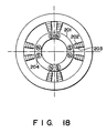
- Fig. 18 shows magnetizing method of the permanent magnet having eight magnetic poles.
- a magnetizing apparatus having eight cores 202 and eight coils 203 is arranged around a ring-shaped magnetic material 204. Electric current is provided for coils 203, so that eight magnetic poles are formed on magnetic material 204.
- eight cores 202 is correctly positioned on magnetizing apparatus, eight magnetic poles are formed on magnetic material 204 correctly.
- the strength of magnetic filed can be changed by current strength and winding times of the coil.
- magnetizing apparatus can be positioned on inside of ring-shaped magnetic material 204.
- the electron gun assembly 62 of the color cathode ray tube apparatus embodied by the invention incorporates the following; three units of independent cathodes 130 which are aligned on a rank in horizontal direction, an electron beam generator GE consisting of the first and second grids 131 and 132 which respectively control electrons emitted from those independent cathodes 130, and an electron lens section consisting of the third through sixth grids 133 through 136 which respectively accelerate and focus those three electron beams R, G, and B, emitted from the electron beam generator GE.
- a convergence cup 137 is provided for the sixth grid 136.
- a heater 138 is provided in order to heat those three independent cathodes 130.
- Those first, second and the fourth grids 131, 132, and 134 are substantially plate-like electrodes which are respectively provided with three through-holes allowing permeation of electron beams emitted from those three independent cathodes 130.
- the third, fifth, and the sixth grids 133, 135, and 136 are respectively the integrally structured cylindrical electrodes which are respectively provided with three through holes to allow permeation of electron beams emitted from those three independent cathodes 130.
- the intervals between those through holes allowing permeation of a pair of side electron beams concretely, those intervals Sg between the aligned direction of a pair of side electron beams passing through the main lens section are adjusted to about 6.6 mm.
- a magnetic field control element consisting of those magnetic members 141a and 141b affecting each other between the magnetic field leaked from the rear region of the deflection device is provided in the periphery of the side-beam permeating holes at the bottom of the convergence cup 137. The magnetic field control element compensates for the coma aberration.
- a pair of vertical deflection coils 82 respectively generate extremely intense barrel-like vertical deflection magnetic field 150.
- extremely intense Lorentz's force affects electron beams, and thus, all the electron beams are compulsorily subject to severe distortion.
- those magnetic poles on both sides of those regions intersecting the axis Y respectively generate intense pin-cushion type magnetic fields 151 and 152 which are inverse form the barrel-like vertical deflection magnetic field 150 so that the intense Lorentz's force can eventually be offset.
- those adverse phenomena like elliptical distortion of beam spots of those three electron beams and inclination of those side electron beams against the horizontal direction are effectively eliminated.
- those magnetic poles on both sides of those regions intersecting the axis X respectively generate intense pin-cushion type magnetic fields 153 and 154. Furthermore, in order to minimize adverse influence of the intense barrel-like vertical deflection magnetic field 150 affecting those side beams, those magnetic poles on both sides of those regions not intersecting axes X and Y respectively generate the other magnetic field 155 which consequently generates specific Lorentz' force inverse from the one generated by the barrel-like vertical deflection magnetic field 150. As a result, the preceding Lorentz's force is offset, thus cancelling the inclination of those side beams against the horizontal direction.
- the intervals La be provided between those magnetic poles on both sides of the axis Y by way of being narrower than the intervals Sg provided for a pair of those side beams in the aligned direction.
- the permanent magnet disc 70 embodied by the invention easily corrects spots of those three electron beams, and in addition, owing to its compact size, the permanent magnet ring 70 is inexpensive and promotes workability for implementing the mass production.
- the preceding color cathode ray tube apparatus added with the auxiliary coil cited above fluctuates the deflection magnetic field by effect of deflection current, and thus, when compensating for the spot shape of those three electron beams by applying the added auxiliary coil, depending on the position of electron beams, correction effect may become too short or excessive.
- the apparatus when applying the color cathode ray tube apparatus using the permanent magnet disc 70 embodied by the invention, the apparatus can stably correct magnetic field all the time. In other words, neither shortage nor excess occurs in the effect of correcting the beam spot shape irrelevant of the position of the electron beams. As a result, electron beam spot can constantly be shaped into perfectly circular form all over the phosphors screen.
- the line of magnetic force may deviate itself from the correct direction, and as a result, the magnetic poles cannot be set to correct positions.
- the permanent magnet ring 70 embodied by the invention can discretely provide a plurality of magnetic poles, all the magnetic poles can precisely be set to the predetermined positions.
- the disc-shaped permanent magnet 70 embodied by the invention can easily generate axially symmetrical corrective magnetic field, thus eventually achieving improved focus characteristic without causing the convergence characteristic to be lowered.
- Fig. 12 designates the second embodiment of the permanent magnet disc 70. Except for the ring-shaped permanent magnet 70 introduced to the first embodiment, the second embodiment uses those components exactly identical to those of the first embodiment.
- the second embodiment provides a pair of permanent magnet members for making up an integral permanent magnet disc. Concretely, those permanent magnet members 161a and 161b are respectively provided with four magnetic poles. These four magnetic poles provided for each of these permanent magnet members 161a and 161b are symmetrically positioned, which are conjunctionally united to complete a disc-shaped permanent magnet 162 like the one provided for the first embodiment.
- the complete permanent magnet disc 162 yields satisfactory effect identical to that is generated by the disc-shaped permanent magnet 70 of the first embodiment.
- Figs. 13 and 14 respectively designate modified examples of the permanent magnet 162 of the second embodiment.
- those magnet poles on a pair of permanent magnet member 171a and 171b and another pair of permanent magnet members 181a and 181b are positioned apart from each other in the structure of those permanent magnets 172 and 182. Provision of these magnetic poles at discrete positions minimizes mutual interference of those magnetic poles to effectively promote magnetization.
- the scope of the second embodiment does not solely specify the number of applicable permanent magnet to be only two pieces, but a minimum of three permanent magnet members may also be introduced as well.
- the above first and second embodiments respectively provided the ring-shaped permanent magnet at a specific position corresponding to an end of the electron gun.
- the third embodiment shown in Fig. 15 secures the permanent magnet disc 28 between the core 24 and the rear end region 27 of the electron gun.
- the ring-shaped permanent magnet may also be composed of a pair of semicircular shaped permanent magnet members 164a and 164b in union. Nevertheless, it is of course possible for the third embodiment to provide the permanent magnet disc which can be composed of three or more than three of component members instead of merely specifying the available number to be only two pieces of permanent magnet member. The same also applied to the second embodiment as well.
- the first, second and the third embodiments respectively secure the permanent magnet disc to the deflection device.
- the invention provides another embodiment which directly installs the permanent magnet disc to the electron-gun assembly 20.
- the electron-gun assembly 20 comprises the following; three independent cathodes 30 which are aligned on a rank in the horizontal direction, an electron beam generator incorporating the first and second grids 31 and 32 which respectively control electron beam emitted from those three independent cathodes 30, and an electron lens section incorporating the third and fourth grids 33 and 34 which respectively accelerate and focus those three electron beams emitted from the electron beams generator.
- a magnetic field control element consisting of a pair of magnetic members 41a and 41b is installed in the periphery of the side-beam permeating through holes at the bottom of the convergence cup 37 secured to the fourth grid 34.
- the permanent magnet disc 28 is secured to the internal surface of the convergence cup 37, where the permanent magnet ring 28 generates eight-pole magnetic field which is symmetrical of both sides of the center axis 55 of the electron gun assembly 20.
- the permanent magnet ring 28 substantially makes up a region allowing permeation of electron beams on the side of the electron gun assembly 20 of the deflection device, and yet, the permanent magnet disc 28 may be installed to a position much closer to the deflection device than the electron lens section of the electron gun assembly 20.
- the whole substance of the permanent magnet disc may not necessarily be magnetic, but the magnetism may merely be present in those regions accommodating those magnetic poles. Needless to say, the process for magnetizing the magnetic members shall precede the process for installing the color cathode ray tube to the apparatus.
- the color cathode ray tube apparatus embodied by the invention incorporates an electron gun which emits three electron beams aligned on a rank and a deflection device which generates deflected magnetic field deflecting those three electron beams emitted from the electron gun in the aligned direction and in the direction orthogonally intersecting the aligned direction.
- the ring-shaped permanent magnet generating eight-pole magnetic field is disposed at a position on the side of the electron gun of the deflection device or at a position close to electrons on the side of the phosphorous screen of the main lens section of the electron gun assembly.
- the circular permanent magnet disceasily promotes magnetization of magnetic poles, and yet, the permanent magnet disc itself is integrated with those magnetic poles which are precisely magnetized and secured to the predetermined positions, and as a result, the permanent magnet disc correctly generates eight-pole magnetic field in perfect symmetry.
Description
- The present invention relates to a deflection device for a color cathode ray tube apparatus featuring improved focus characteristic by effect of minimized deflection aberration.
- A color cathode ray tube apparatus of shadow mask type comprises a panel section having a generally rectangular face plate and a skirt extending from a lateral edge of the face plate, a funnel section connected to the panel section, and a neck section continuously formed with the funnel section. The interior of the cathode ray tube is maintained in a vacuum state by the panel section, the funnel section and the neck section. In the neck section is housed an electron gun assembly which generates three electron beams (R), (G) and (B). At the outer lateral side of the portion of the apparatus between the funnel section and the neck section is disposed a deflection device for generating magnetic fields which deflect electron beams vertically and horizontally. A phosphor screen is formed on the inner face of the face plate of the panel. In the tube, a generally rectangular shadow mask is opposed to the face plate at a predetermined spacing. The shadow mask is made of a thin metal plate and provided with a lot of slit apertures.
- The deflection device for use in the color cathode ray tube apparatus of shadow mask type has a horizontal deflection coil and a vertical deflection coil which produce magnetic fields for respectively horizontally and vertically deflecting the three electron beams (R), (G), (B) emitted from the electron gun assembly. After being deflected by the horizontal and vertical deflection coils, the three electron beams (R), (G) and (B) are converged towards the corresponding slit. The electron beams (R), (G) and (B) converged at the vicinity of the slit are landed on the phosphor screen which has three kinds of phosphor stripes alternately arranged to each other. The three electron beams (R), (G) and (B) pass the slit and are incident on the phosphor screen, thereby the red light, green light and blue light are emitted from the phosphor stripes. In other words, the three beams are landed on the corresponding phosphor stripes which emit the red, green and blue light.
- When the electron gun assembly is of inline type, the electron beam (G) which causes green light to be emitted is radiated from the electron gun so as to coincide with the tube axis. The electron beams (B) and (R) which cause blue light and red light to be emitted, respectively, are radiated, with the electron beam (G) disposed therebetween. The color cathode ray tube apparatus, which employs the characteristic of the inline type electron gun to produce specific non-uniform magnetic fields by means of deflection yokes, is a self-convergence type color cathode ray tube apparatus. With the color cathode ray tube of this type in which the three electron beams are radiated on the same horizontal plane, for example, a horizontal deflection magnetic field of mainly pincushion type and a vertical deflection magnetic field of mainly barrel type are applied. The impression of these magnetic fields enables the three electron beams radiated on the same horizontal plane to be converged on the phosphor screen.
- However, with this inline type color cathode ray tube apparatus, the center beam (G) and the side beams (B) and (R) do not converge well but produce coma aberration on the peripheral portion of the screen. Japanese Patent Publications No. Sho 51-26208 and Sho 54-23208 describe an apparatus wherein an electron gun assembly is provided, for the correction of the coma aberration, with magnetic substance which changes the shape of the after-leakage magnetic field which is a part of the magnetic field generated by the deflection device. Japanese Utility Model Publication No. Sho 57-45748 discloses another apparatus in which an auxiliary coil is provided at the side of the electron gun of a deflection device and is adapted to render an electrical current to flow in synchronism with the deflection current flowing in a vertical deflection coil, thereby generating a strong pincushion type magnetic field.
- Nevertheless, even when applying such a color cathode ray tube apparatus incorporating the structure mentioned above, the shape of the beam spot of those three electron beams hitting against the fluorescent surface is subject to distortion due to presence of magnetic field. Fig. 1 designates this condition. If these three electron beams where subject to deflection by effect of uniform magnetic filed, the shape of beam spots of these three electron beams remains circular all over the fluorescent surface. On the other hand, as shown in Fig. 2A, if these three electron beams were subject to deflection due to presence of non-uniform magnetic field, then, since each
electron beam 13 receives horizontal Lorentz's force, the shape of beam spots at the end of the horizontal axis (axis X) of thefluorescent surface 14 distorts into a horizontally extended elliptical state. On the other hand, as shown in Fig. 2B, the direction of Lorentz's force on both sides of the vertical axis (axis Y) also differs from each other. As a result, the beam-spot shapes - Furthermore, the method of disposing the auxiliary coil described in the Japanese Laid-Open Utility Model Publication No. 57-45748 of 1982 cited above still contains technical problems described below.
- Flow of current synchronized with deflection current flowing through the vertical deflection coil cause magnetic filed to be generated in the horizontal direction on the horizontal axis which is available for deflecting electron beams in the vertical direction. As a result of the presence of this magnetic field, each electron beam receives excessive effect of deflection in the direction of the vertical axis on the side of the electron-gun assembly in the deflection magnetic field range. As a result, each electron beam easily hits against the inner wall of the neck section. If this phenomenon occurs, some regions devoid of incoming electron beams (conventionally called "neck shadow") will be generated on the fluorescent surface. Furthermore, since the above-cited auxiliary coil contains a coil wound on a magnetic member in order to allow current to flow through the coil, considering the nature of being an auxiliary element, it is by no means economical to use.
- When assembling a TV set using a color cathode ray tube, in compliance with the request from the set maker, impedance of the deflection device is often variable. If the impedance of the deflection device were changed, then, current flowing through the deflection coil fluctuates. As a result, in order to offset influence of the auxiliary coil affecting the deflection device, it is essential for the TV manufacturers to change specification of the auxiliary coil in correspondence with the impedance of the deflection coil, and thus, the color cathode ray tube using the above auxiliary coil involves poor compatibility with the mass production.
- To solve those technical problems cited above, there is another color cathode ray tube apparatus disclosed in EP-A-348912. According to the structure of this color cathode ray tube apparatus, two pairs of permanent magnets 10a/10b and 10c/10d are respectively disposed between the electron lens side of the electron gun assembly and an
edge 3 of adeflection device 2 shown in Fig. 3. Magnetic poles of these permanent magnets are disposed in the direction inverse from each other by way of surrounding the periphery of the axis Z. Of these, a pair ofpermanent magnets 10a and 10b are disposed on the vertical axis (axis Y), whereas the other pair ofpermanent magnets 10c and 10d are respectively disposed on the horizontal axis (axis X). To compensate for the deflection aberration caused by deflection magnetic field generated by thesecond deflection coil 4, those two pairs of permanent magnets 10a through 10d respectively generate pin-cushion type magnetic field. - Those
permanent magnets 10a and 10b are disposed on the axis X orthogonally intersecting the aligned direction of three electron beams, where thesepermanent magnets 10a and 10b respectively generate pin-cushion type magnetic filed. The pin-cushion type magnetic field generates specific Lorentz's force which compensates for the deformation of the beam spot shape of three electron beams caused by the other Lorentz's force of the barrel-type deflection magnetic filed generated by the second deflection coil. By virtue of this inverse Lorentz's force, independent of influence from the barrel-type deflection magnetic field generated by the second deflection coil, those three electron beams can be prevented from deforming themselves into elliptical shape, and yet, a pair of side beams B and R can also be prevented from deforming themseleves in the oblique direction. - Furthermore, the other pair of permanent magnetic 10c and 10d are respectively disposed on the axis X which is in parallel with the aligned direction of these three electron beams, where these
permanent magnets 10c and 10d respectively generate specific Lorentz's force inverse from the other Lorentz's force of the barrel-type deflection magnetic filed generated by the second deflection coil. By virtue of this inverse Lorentz's force, independent of influence of the barrel-type deflection magnetic filed generated by thesecond deflection coil 4, a pair of side beams B and R can be prevented from deforming themseleves in the oblique direction. - Nevertheless, recently, still higher convergence characteristic and focus characteristic are demanded for the high-definition TV set containing 16:9 of the aspect ratio and the high-precision tube as well. Based on this reason, any conventional convergence and focus characteristics are no longer acceptable for application. More particularly, this is because of those reasons described below.
- In the course of producing bar-shaped
permanent magnets 10 available for the color cathode ray tube apparatus cited above, a large number ofpermanent magnets 6 are simultaneously magnetized in presence of the magnetizing magnetic filed 8 shown in Fig. 4. As shown in Fig. 4, strictly speaking, the magnetizing magnetic filed 8 curves itself, and thus, like the direction of magnetizing those bar-shapedpermanent magnets 10 shown in Fig. 5, the magnetizing magnetic filed 8 deviates itself from the center-axial direction. Because of this, the direction of the magnetic poles of the permanent magnet respectively deviate form the center-axial direction of the bar-shaped permanent magnet. Furthermore, since these fourpermanent magnets 10 conjunctionally generate eight-pole magnetic field, in order to symmetrically distribute magnetic field, these four permanent magnets must respectively be disposed at correct positions. Nevertheless, since four permanent magnets are needed, it is extremely difficult for the above conventional art to precisely dispose all of these fourpermanent magnets 10 to ensure perfectly symmetrically distribution of magnetic field. As a result, the prior apparatus cannot properly balance the convergence effect, and thus, it results in the incorrectly crossed convergence for example. In consequence, when disposing those four permanent magnets in the deflection device, beam shape cannot precisely be corrected, and therefore, the prior color cathode ray tube apparatus cannot correctly converge three electron beams. - Prior art document EP-A-59 004 discloses a picture display device having a display tube and a self-converging system of deflection coils. In this display device, focusing is substantially independent of the deflection by the system of the deflection coils and takes place by means of two quadrupole lenses and a focusing lens. Also an eight-pole magnetic lens can be used.
- Finally, prior art document EP-A-53 853 describes a cathode-ray tube and a deflection unit. In this cathode-ray tube an eight-pole magnetic field is generated in a region closer to the screen than the center of the deflection yoke.
- The object of the invention is to fully solve the technical problems as mentioned above by providing a novel deflection device capable of securely providing satisfactory focus characteristics throughout the whole screen surface without degrading the convergence characteristics at all.
- To solve this object the present invention provides a deflection device as specified in claim 1 or 8.
- The deflection device embodied by the invention characteristically incorporates a single unit of eight-pole permanent magnet disc capable of precisely positioning a plurality of magnetic poles between the end of the deflection device on the side of the electron gun and the electron gun itself. By virtue of this structural arrangement, spots of electron beams on the fluorescent surface is very close to circular shape.
- This invention can be more fully understood from the following detailed description when taken in conjunction with the accompanying drawings, in which:
- Fig. 1 designates shapes of electron beam spots generated by a conventional color cathode ray tube apparatus;
- Fig. 2A and 2B schematically designate Lorentz's force generated by a conventional color cathode ray apparatus when affecting electron beams;
- Fig. 3 is a perspective view of the deflection device of a conventional color cathode ray tube apparatus;
- Fig. 4 is a plan designating the state in which a permanent magnet is in the course of receiving magnetization;
- Fig. 5 is a perspective view of a magnetized permanent magnet;
- Fig. 6 is a sectional view of the color cathode ray tube apparatus according to an embodiment of the invention;
- Fig. 7 is a perspective view of the deflection device of the color cathode ray tube apparatus embodied by the invention;
- Figs. 8A and 8B are plans designating an eight-pole permanent magnet provided for the deflection device shown in Fig. 7;
- Figs. 9A and 9B are sectional views of the electron-gun assembly of the color cathode ray tube apparatus embodied by the invention;
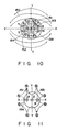
- Fig. 10 is a plan designating distribution of magnetic field in the periphery of the eight-pole permanent magnet provided for the color cathode ray tube apparatus embodied by the invention;
- Fig. 11 is a plan designating distribution of magnetic field in those regions neighboring the eight-pole permanent magnet provided for the color cathode ray tube apparatus embodied by the invention;
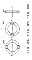
- Figs. 12A through 12C are respectively the plans designating the eight-pole permanent magnets of the deflection device of the color cathode ray tube apparatus according to the second embodiment of the invention;
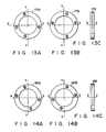
- Figs. 13A through 13C are respectively the plans designating modified examples of the eight-pole permanent magnet of the deflection device according to the second embodiment;
- Figs. 14A through 14C are respectively the plans designating other modified examples of the eight-pole permanent magnet of the deflection device according to the second embodiment;
- Fig. 15 is a plan designating another modified example of the eight-pole permanent magnet of the deflection device according to the third embodiment of the invention;
- Fig. 16 is a plan designating a still further modified example of the eight-pole permanent magnet of the deflection device according to the third embodiment of the invention;
- Fig. 17A is a sectional view of an electron-gun assembly according to the fourth embodiment;
- Fig. 17B is a plan designating an electron-gun assembly according to the fourth embodiment; and
- Fig. 18 is a plan designating a magnetizing apparatus and a magnetic material.
- Referring now more particularly to the accompanying drawing, details of the color cathode ray tube apparatus embodied by the invention are described below.
- Fig. 6 is a sectional view of the color cathode ray tube apparatus according to the first embodiment of the invention. The color cathode
ray tube apparatus 50 incorporates the following; apanel section 52 which is internally provided with a substantiallyrectangular face plate 54 and askirt 51 which extends itself from the side edge of theface plate 54, afunnel section 58 which is connected to thepanel section 52, and anenvelope member 61 which envelopes aneck section 60 connected to thefunnel section 58. Thepanel section 52, thefunnel section 58, and theneck section 60, conjunctionally hold the interior of the color cathode ray tube in perfect vacuum. Theneck section 60 incorporates an electron-gun assembly 62 which generates three electron beams R, G, and B. - A
deflection device 64 is provided with a pair of horizontal deflection coils 80 generating specific magnetic field which deflects those three electron beams R, G, and B in the horizontal direction and a pair of vertical deflection coils 82 generating specific magnetic field which deflects those three electron beams R, G, and B in the vertical direction. Thedeflection device 64 is secured to the external surface of thefunnel section 58 and theneck section 60. A ring-shapedpermanent magnet 70 incorporating eight magnetic poles is secured to thedeflection device 64 at the position close to the electron-gun assembly 62. - A
phosphor screen 74 is provided on the inner surface of theface plate 54 of thepanel section 52.Shadow mask 76 of substantially rectangular shape is disposed inside of the color cathode ray tube in opposition from thephosphor screen 74 at the predetermined intervals. Theshadow mask 76 is made of extremely thin metallic sheets and provided with a large number of through holes. Amask frame 78 is provided in the periphery of theseshadow masks 76 in order to support them. Themask frame 78 is secured to thepanel section 52 by means of a plurality of elastic supporters (not shown). - Fig. 7 is an enlarged perspective view of the
deflection device 64, which incorporates a pair of saddle-type horizontal deflection coils 80 symmetrically being disposed in the vertical (Y-axial) direction of aseparator 83 and a pair of troidal-type vertical deflection coils 82 wound on acore 84, respectively. Synchronized currents each having a different value compatible with those deflection coils 80 and 83 are respectively delivered to passive circuits (not shown) which incorporates those elements like resistors and line concentrators. The ring-shapedpermanent magnet 70 secured to thedeflection device 64 on the side of the electron-gun assembly 62 is integrally provided with eight magnetic poles in the periphery of the tubular axis Z. - As shown in Fig. 8A and 8B, those eight magnetic poles provided for the
permanent magnet 70 are alternately disposed. The intervals provided between these magnetic poles which are disposed at specific positions close to both sides of the axes X and Y are substantially narrower than those intervals between those magnetic poles which are apart from those axes X and Y. In addition, those two pairs of magnetic poles, in other words, four magnetic poles, which are disposed at specific positions close to both sides of the axis X respectively contain magnetic force being equal to each other. Likewise, those two pairs of magnetic poles (i.e., four magnetic poles) which are disposed at specific positions close to both sides of the axis Y also contain magnetic force being equal to each other. On the other hand, those two pairs of magnetic poles (i.e., four magnetic poles) which are disposed at those positions close to both sides of the axis X respectively contain such magnetic force weaker than that is held by those two pairs (i.e., four magnetic poles) of magnetic poles disposed at those positions close to both sides of the axis Y. When viewing from the phosphorous screen and assuming the presence of plan relied by the axes X and Y, these magnetic poles alternately invert themselves clockwise based on the N-pole which is made of the magnetic pole closest to the axis Y in the first quadrant at the upper right position. - Next, an actual example of the
permanent magnet disc 70 is described below. Actually, thepermanent magnet ring 70 has 30 mm of inner diameter, 33 mm of outer diameter, 5 mm of width, 6 mm of intervals La between those magnetic poles intersecting the axis Y, 5 mm of intervals Lb between those magnetic poles intersecting the axis x, and 26.5 mm of intervals La between those magnetic poles which do not intersect normal axis, respectively. This embodiment provides 1.300 Gauss per centimeter of superficial flux density for those magnetic pole intersecting the axis X, and provides 1,500 Gauss per centimeter of the superficial density for those magnetic poles intersecting the axis Y, respectively. - Fig. 18 shows magnetizing method of the permanent magnet having eight magnetic poles. A magnetizing apparatus having eight
cores 202 and eightcoils 203 is arranged around a ring-shapedmagnetic material 204. Electric current is provided forcoils 203, so that eight magnetic poles are formed onmagnetic material 204. As eightcores 202 is correctly positioned on magnetizing apparatus, eight magnetic poles are formed onmagnetic material 204 correctly. Furthermore, the strength of magnetic filed can be changed by current strength and winding times of the coil. In other method, magnetizing apparatus can be positioned on inside of ring-shapedmagnetic material 204. - As shown in Fig. 9A and 9B, the
electron gun assembly 62 of the color cathode ray tube apparatus embodied by the invention incorporates the following; three units ofindependent cathodes 130 which are aligned on a rank in horizontal direction, an electron beam generator GE consisting of the first andsecond grids independent cathodes 130, and an electron lens section consisting of the third throughsixth grids 133 through 136 which respectively accelerate and focus those three electron beams R, G, and B, emitted from the electron beam generator GE. - A
convergence cup 137 is provided for thesixth grid 136. Aheater 138 is provided in order to heat those threeindependent cathodes 130. Those first, second and thefourth grids independent cathodes 130. On the other hand, the third, fifth, and thesixth grids independent cathodes 130. - In contrast with the intervals (La = 6 mm) provided between those S-poles and N-poles of the
permanent magnet disc 70, the intervals between those through holes allowing permeation of a pair of side electron beams, concretely, those intervals Sg between the aligned direction of a pair of side electron beams passing through the main lens section are adjusted to about 6.6 mm. In addition, a magnetic field control element consisting of thosemagnetic members 141a and 141b affecting each other between the magnetic field leaked from the rear region of the deflection device is provided in the periphery of the side-beam permeating holes at the bottom of theconvergence cup 137. The magnetic field control element compensates for the coma aberration. - By virtue of the provision of the disc-shaped
permanent magnet 70 for thedeflection device 64 on the side of theelectron gun assembly 62, a variety of advantageous effects can be achieved, which are described below. - As shown in Fig. 10, a pair of vertical deflection coils 82 respectively generate extremely intense barrel-like vertical deflection
magnetic field 150. As a result, extremely intense Lorentz's force affects electron beams, and thus, all the electron beams are compulsorily subject to severe distortion. In order to minimize adverse effect of the intense barrel-like vertical deflection magnetic filed 150 affecting electron beams, those magnetic poles on both sides of those regions intersecting the axis Y respectively generate intense pin-cushion typemagnetic fields magnetic field 150 so that the intense Lorentz's force can eventually be offset. As a result, those adverse phenomena like elliptical distortion of beam spots of those three electron beams and inclination of those side electron beams against the horizontal direction are effectively eliminated. - Like the one taking place in the Y-axial direction, those magnetic poles on both sides of those regions intersecting the axis X respectively generate intense pin-cushion type
magnetic fields magnetic field 150 affecting those side beams, those magnetic poles on both sides of those regions not intersecting axes X and Y respectively generate the othermagnetic field 155 which consequently generates specific Lorentz' force inverse from the one generated by the barrel-like vertical deflectionmagnetic field 150. As a result, the preceding Lorentz's force is offset, thus cancelling the inclination of those side beams against the horizontal direction. - To effectively promote useful effect of the magnetic field in favor of those side electron beams, it is suggested that the intervals La be provided between those magnetic poles on both sides of the axis Y by way of being narrower than the intervals Sg provided for a pair of those side beams in the aligned direction.
- In contrast with the color cathode ray tube added with the auxiliary coil described in the preceding Japanese Laid-Open Utility Model Publication No. 57-45748 of 1982, the
permanent magnet disc 70 embodied by the invention easily corrects spots of those three electron beams, and in addition, owing to its compact size, thepermanent magnet ring 70 is inexpensive and promotes workability for implementing the mass production. The preceding color cathode ray tube apparatus added with the auxiliary coil cited above fluctuates the deflection magnetic field by effect of deflection current, and thus, when compensating for the spot shape of those three electron beams by applying the added auxiliary coil, depending on the position of electron beams, correction effect may become too short or excessive. - On the other hand, when applying the color cathode ray tube apparatus using the
permanent magnet disc 70 embodied by the invention, the apparatus can stably correct magnetic field all the time. In other words, neither shortage nor excess occurs in the effect of correcting the beam spot shape irrelevant of the position of the electron beams. As a result, electron beam spot can constantly be shaped into perfectly circular form all over the phosphors screen. - When magnetizing any conventional bar-shaped permanent magnet, the line of magnetic force may deviate itself from the correct direction, and as a result, the magnetic poles cannot be set to correct positions. On the other hand, since the
permanent magnet ring 70 embodied by the invention can discretely provide a plurality of magnetic poles, all the magnetic poles can precisely be set to the predetermined positions. As a result, the disc-shapedpermanent magnet 70 embodied by the invention can easily generate axially symmetrical corrective magnetic field, thus eventually achieving improved focus characteristic without causing the convergence characteristic to be lowered. - Fig. 12 designates the second embodiment of the
permanent magnet disc 70. Except for the ring-shapedpermanent magnet 70 introduced to the first embodiment, the second embodiment uses those components exactly identical to those of the first embodiment. The second embodiment provides a pair of permanent magnet members for making up an integral permanent magnet disc. Concretely, thosepermanent magnet members 161a and 161b are respectively provided with four magnetic poles. These four magnetic poles provided for each of thesepermanent magnet members 161a and 161b are symmetrically positioned, which are conjunctionally united to complete a disc-shapedpermanent magnet 162 like the one provided for the first embodiment. The completepermanent magnet disc 162 yields satisfactory effect identical to that is generated by the disc-shapedpermanent magnet 70 of the first embodiment. - Figs. 13 and 14 respectively designate modified examples of the
permanent magnet 162 of the second embodiment. To execute this modification, those magnet poles on a pair ofpermanent magnet member 171a and 171b and another pair ofpermanent magnet members 181a and 181b are positioned apart from each other in the structure of thosepermanent magnets - The above first and second embodiments respectively provided the ring-shaped permanent magnet at a specific position corresponding to an end of the electron gun. On the other hand, the third embodiment shown in Fig. 15 secures the
permanent magnet disc 28 between the core 24 and therear end region 27 of the electron gun. To introduce the third embodiment, as shown in Fig. 16, the ring-shaped permanent magnet may also be composed of a pair of semicircular shapedpermanent magnet members 164a and 164b in union. Nevertheless, it is of course possible for the third embodiment to provide the permanent magnet disc which can be composed of three or more than three of component members instead of merely specifying the available number to be only two pieces of permanent magnet member. The same also applied to the second embodiment as well. - The first, second and the third embodiments respectively secure the permanent magnet disc to the deflection device. The invention provides another embodiment which directly installs the permanent magnet disc to the electron-
gun assembly 20. The electron-gun assembly 20 comprises the following; threeindependent cathodes 30 which are aligned on a rank in the horizontal direction, an electron beam generator incorporating the first andsecond grids independent cathodes 30, and an electron lens section incorporating the third andfourth grids magnetic members 41a and 41b is installed in the periphery of the side-beam permeating through holes at the bottom of theconvergence cup 37 secured to thefourth grid 34. Thepermanent magnet disc 28 is secured to the internal surface of theconvergence cup 37, where thepermanent magnet ring 28 generates eight-pole magnetic field which is symmetrical of both sides of thecenter axis 55 of theelectron gun assembly 20. - According to this structural arrangement, the
permanent magnet ring 28 substantially makes up a region allowing permeation of electron beams on the side of theelectron gun assembly 20 of the deflection device, and yet, thepermanent magnet disc 28 may be installed to a position much closer to the deflection device than the electron lens section of theelectron gun assembly 20. - It should be understood that the whole substance of the permanent magnet disc may not necessarily be magnetic, but the magnetism may merely be present in those regions accommodating those magnetic poles. Needless to say, the process for magnetizing the magnetic members shall precede the process for installing the color cathode ray tube to the apparatus.
- The color cathode ray tube apparatus embodied by the invention incorporates an electron gun which emits three electron beams aligned on a rank and a deflection device which generates deflected magnetic field deflecting those three electron beams emitted from the electron gun in the aligned direction and in the direction orthogonally intersecting the aligned direction. The ring-shaped permanent magnet generating eight-pole magnetic field is disposed at a position on the side of the electron gun of the deflection device or at a position close to electrons on the side of the phosphorous screen of the main lens section of the electron gun assembly. The circular permanent magnet disceasily promotes magnetization of magnetic poles, and yet, the permanent magnet disc itself is integrated with those magnetic poles which are precisely magnetized and secured to the predetermined positions, and as a result, the permanent magnet disc correctly generates eight-pole magnetic field in perfect symmetry. By virtue of the above structural advantage, by effectively applying precisely controlled magnetic field generated by the permanent magnetic disc, deflective aberration affecting those electron beams from the deflection magnetic field generated by the deflection device can fully be corrected. As a result, the focus characteristic is securely promoted in the periphery of the phosphor screen.
Claims (8)
- A deflection device (64) which is suitable for a color cathode ray tube apparatus comprising a panel section (52), a funnel section (58), and a neck section (60) internally securing an electron-gun assembly (62), said deflection device comprising:a first deflection coil (80) which deflects three electron beams (B,R,G) emitted from said electron-gun assembly (62) in the in-line direction substantially in the horizontal X-axial direction;a second deflection coil (82) which deflects said three electron beams emitted from said electron-gun assembly (62) in the vertical Y-axial direction; andan eight-pole permanent magnet means (70) which is provided around the tubular axis (2-axis) between an end region of said deflection device (64) and a main electron lens section of said electron-gun assembly (62), for generating magnetic fields capable of minimizing deflective aberration of said three electron beams caused by the magnetic field of said deflection device,characterized in thatsaid eight-pole permanent magnet means (70) comprises a circular doughnut-like disc whereon the eight poles are formed.
- A deflection device according to claim 1, characterized in that said eight-pole permanent magnet means (70) is substantially composed of a plurality of circular doughnut-like plates.
- A deflection device according to claim 1, characterized in that said eight-pole permanent magnet means (70) comprises magnetic rings arranged along the tubular axis, or is divided into two pieces in the direction perpendicular to the tubular axis.
- A deflection device according to claim 1, characterized in that intervals between two pairs of magnetic poles which are disposed at specific positions close to both sides of an axis in X-axial direction of said eight-pole permanent magnet means (70) and intervals between other two pairs of magnetic poles disposed at specific positions close to both sides of an axis in Y-axial direction of said eight-pole permanent magnet means (70) are respectively narrower than those intervals between four pairs of magnetic poles which are apart from said axes in X- and Y-axial directions.
- A deflection device according to claim 1, characterized in that two pairs of magnetic poles which are disposed at specific positions close to both sides of an axis in X-axial direction and other two pairs of magnetic poles disposed at specific positions close to both sides of an axis in Y-axial direction are respectively provided with specific magnetic polar intensity equal to each other.
- A deflection device according to claim 1, characterized in that intervals between two pairs of magnetic poles disposed at specific positions close to both sides of an axis in Y-axial direction are narrower than the interval between a pair of side electron beams emitted from said electron gun assembly (62).
- A deflection device according to claim 1, characterized in that, assuming presence of a plane across axes in X- and Y-axial directions in said eight-pole permanent magnet means (70) viewing from a phosphorous screen, substantially, N-pole is the magnetic pole which is closest to the axis in X-axial direction in clockwise direction.
- A deflection device which is suitable for a color cathode ray tube apparatus comprising a panel section (52), a funnel section (58), and a neck section (60) internally securing an electron-gun assembly (62), comprising:a first deflection coil (80) which deflects three electron beams (B,R,G) emitted from said electron-gun assembly (62) in the in-line direction substantially in the horizontal X-axial direction;a second deflection coil (82) which deflects said three electron beams emitted from said electron-gun assembly (62) in the vertical Y-axial direction;a core (24) which accommodates said second deflection coil (82) wound thereon; andan eight-pole permanent magnet means (70) which is provided around the tubular axis (z-axis) for generating a magnetic field capable of minimizing deflective aberration of said three electron beams caused by the magnetic field of said deflection device,characterized in thatsaid eight-pole permanent magnet means (70) is provided between an end region of said deflection device and said core (24) and comprises a circular doughnut-like disc, whereon the eight poles are formed.
Applications Claiming Priority (2)
| Application Number | Priority Date | Filing Date | Title |
|---|---|---|---|
| JP118683/90 | 1990-05-10 | ||
| JP2118683A JP3034906B2 (en) | 1990-05-10 | 1990-05-10 | Color picture tube and deflection device |
Publications (3)
| Publication Number | Publication Date |
|---|---|
| EP0456224A2 EP0456224A2 (en) | 1991-11-13 |
| EP0456224A3 EP0456224A3 (en) | 1993-02-24 |
| EP0456224B1 true EP0456224B1 (en) | 1996-03-27 |
Family
ID=14742615
Family Applications (1)
| Application Number | Title | Priority Date | Filing Date |
|---|---|---|---|
| EP19910107505 Expired - Lifetime EP0456224B1 (en) | 1990-05-10 | 1991-05-08 | Color cathode ray tube apparatus |
Country Status (3)
| Country | Link |
|---|---|
| EP (1) | EP0456224B1 (en) |
| JP (1) | JP3034906B2 (en) |
| DE (1) | DE69118235T2 (en) |
Cited By (1)
| Publication number | Priority date | Publication date | Assignee | Title |
|---|---|---|---|---|
| TWI771003B (en) * | 2020-06-17 | 2022-07-11 | 漢辰科技股份有限公司 | Hybrid magnet structure |
Families Citing this family (3)
| Publication number | Priority date | Publication date | Assignee | Title |
|---|---|---|---|---|
| DE69507344T2 (en) | 1995-01-24 | 1999-09-09 | Ibm | METHOD AND DEVICE FOR GRID DEMODULATION |
| DE69818569T2 (en) * | 1997-07-15 | 2004-08-05 | Hitachi, Ltd. | Color cathode ray tube |
| TW412056U (en) * | 1998-10-26 | 2000-11-11 | Koninkl Philips Electronics Nv | Picture display device comprising a deflection unit, and deflection unit for such a picture display device |
Family Cites Families (7)
| Publication number | Priority date | Publication date | Assignee | Title |
|---|---|---|---|---|
| BE535542A (en) * | 1954-02-09 | |||
| FR2290029A1 (en) * | 1974-10-30 | 1976-05-28 | Videon Sa | Electron beam static convergence adjuster for colour CRT - has two pairs of permanent magnet ring, each pair with single rotation device |
| GB1534814A (en) * | 1976-07-05 | 1978-12-06 | Tdk Electronics Co Ltd | Convergence control unit for television set |
| NL8006628A (en) * | 1980-12-05 | 1982-07-01 | Philips Nv | CATHODE SPRAY TUBE - DEFLECTION UNIT COMBINATION WITH HIGH RESOLUTION. |
| NL8100785A (en) * | 1981-02-18 | 1982-09-16 | Philips Nv | DEVICE FOR DISPLAYING IMAGES. |
| NL8600355A (en) * | 1986-02-13 | 1987-09-01 | Philips Nv | DEVICE FOR DISPLAYING TELEVISION IMAGES AND DEFLECTOR THEREFOR. |
| KR920000940B1 (en) * | 1988-06-27 | 1992-01-31 | 가부시끼가이샤 도시바 | The color picture tube and the deflection yoke apparatus |
-
1990
- 1990-05-10 JP JP2118683A patent/JP3034906B2/en not_active Expired - Fee Related
-
1991
- 1991-05-08 EP EP19910107505 patent/EP0456224B1/en not_active Expired - Lifetime
- 1991-05-08 DE DE1991618235 patent/DE69118235T2/en not_active Expired - Fee Related
Cited By (1)
| Publication number | Priority date | Publication date | Assignee | Title |
|---|---|---|---|---|
| TWI771003B (en) * | 2020-06-17 | 2022-07-11 | 漢辰科技股份有限公司 | Hybrid magnet structure |
Also Published As
| Publication number | Publication date |
|---|---|
| JPH0417238A (en) | 1992-01-22 |
| EP0456224A2 (en) | 1991-11-13 |
| JP3034906B2 (en) | 2000-04-17 |
| DE69118235T2 (en) | 1996-08-22 |
| DE69118235D1 (en) | 1996-05-02 |
| EP0456224A3 (en) | 1993-02-24 |
Similar Documents
| Publication | Publication Date | Title |
|---|---|---|
| US5113112A (en) | Color cathode ray tube apparatus | |
| JPS5832892B2 (en) | Deflection yoke structure for inline beam color cathode ray tube | |
| JPS5811070B2 (en) | color color | |
| EP0456224B1 (en) | Color cathode ray tube apparatus | |
| US5225736A (en) | Color cathode ray tube apparatus | |
| JP3638311B2 (en) | Color picture tube | |
| EP0073005B1 (en) | Color cathode ray tube device | |
| US4857796A (en) | Cathode-ray tube with electrostatic convergence means and magnetic misconvergence correcting mechanism | |
| US5177399A (en) | Color cathode ray tube apparatus | |
| US6069438A (en) | Color cathode ray tube with convergence magnet | |
| US5177412A (en) | Color cathode ray tube apparatus | |
| US4881015A (en) | Color cathode-ray apparatus having an improved deflection unit | |
| EP0348912B1 (en) | Color cathode ray tube apparatus | |
| EP0310242B1 (en) | Colour display system including a self-converging deflection yoke providing raster distortion correction | |
| US6060824A (en) | Color cathode ray tube with specific placement of magnetic plate | |
| JP2825265B2 (en) | Color picture tube and deflection device | |
| KR950003512B1 (en) | Color television display tube with coma correction | |
| EP0415125B1 (en) | Cathode ray tube | |
| EP0399467B1 (en) | Color cathode ray tube apparatus | |
| CA1081311A (en) | Method of adjusting a magnetic deflection unit of a cathode ray tube, cathode ray tube having a deflection unit or reference points adjusted according to said method, and a deflection unit provided with reference points adjusted according to said method | |
| JPH1140079A (en) | Color cathode-ray tube and mis-convergence correcting method | |
| JP2862575B2 (en) | Color picture tube | |
| JP3130554B2 (en) | Color picture tube | |
| JP3396503B2 (en) | Color picture tube equipment | |
| JP2859900B2 (en) | Color picture tube |
Legal Events
| Date | Code | Title | Description |
|---|---|---|---|
| PUAI | Public reference made under article 153(3) epc to a published international application that has entered the european phase |
Free format text: ORIGINAL CODE: 0009012 |
|
| 17P | Request for examination filed |
Effective date: 19910605 |
|
| AK | Designated contracting states |
Kind code of ref document: A2 Designated state(s): DE FR GB |
|
| PUAL | Search report despatched |
Free format text: ORIGINAL CODE: 0009013 |
|
| AK | Designated contracting states |
Kind code of ref document: A3 Designated state(s): DE FR GB |
|
| 17Q | First examination report despatched |
Effective date: 19940727 |
|
| GRAH | Despatch of communication of intention to grant a patent |
Free format text: ORIGINAL CODE: EPIDOS IGRA |
|
| GRAA | (expected) grant |
Free format text: ORIGINAL CODE: 0009210 |
|
| AK | Designated contracting states |
Kind code of ref document: B1 Designated state(s): DE FR GB |
|
| REF | Corresponds to: |
Ref document number: 69118235 Country of ref document: DE Date of ref document: 19960502 |
|
| ET | Fr: translation filed | ||
| PLBE | No opposition filed within time limit |
Free format text: ORIGINAL CODE: 0009261 |
|
| STAA | Information on the status of an ep patent application or granted ep patent |
Free format text: STATUS: NO OPPOSITION FILED WITHIN TIME LIMIT |
|
| 26N | No opposition filed | ||
| REG | Reference to a national code |
Ref country code: GB Ref legal event code: 746 Effective date: 19981012 |
|
| REG | Reference to a national code |
Ref country code: FR Ref legal event code: D6 |
|
| REG | Reference to a national code |
Ref country code: GB Ref legal event code: IF02 |
|
| PGFP | Annual fee paid to national office [announced via postgrant information from national office to epo] |
Ref country code: DE Payment date: 20070503 Year of fee payment: 17 |
|
| PGFP | Annual fee paid to national office [announced via postgrant information from national office to epo] |
Ref country code: GB Payment date: 20070502 Year of fee payment: 17 |
|
| PGFP | Annual fee paid to national office [announced via postgrant information from national office to epo] |
Ref country code: FR Payment date: 20070510 Year of fee payment: 17 |
|
| GBPC | Gb: european patent ceased through non-payment of renewal fee |
Effective date: 20080508 |
|
| REG | Reference to a national code |
Ref country code: FR Ref legal event code: ST Effective date: 20090119 |
|
| PG25 | Lapsed in a contracting state [announced via postgrant information from national office to epo] |
Ref country code: FR Free format text: LAPSE BECAUSE OF NON-PAYMENT OF DUE FEES Effective date: 20080602 Ref country code: DE Free format text: LAPSE BECAUSE OF NON-PAYMENT OF DUE FEES Effective date: 20081202 |
|
| PG25 | Lapsed in a contracting state [announced via postgrant information from national office to epo] |
Ref country code: GB Free format text: LAPSE BECAUSE OF NON-PAYMENT OF DUE FEES Effective date: 20080508 |