EP0452485B1 - Disc-type coin sorter with retractable guide surfaces - Google Patents
Disc-type coin sorter with retractable guide surfaces Download PDFInfo
- Publication number
- EP0452485B1 EP0452485B1 EP91901042A EP91901042A EP0452485B1 EP 0452485 B1 EP0452485 B1 EP 0452485B1 EP 91901042 A EP91901042 A EP 91901042A EP 91901042 A EP91901042 A EP 91901042A EP 0452485 B1 EP0452485 B1 EP 0452485B1
- Authority
- EP
- European Patent Office
- Prior art keywords
- coins
- disc
- guide
- coin
- guide surfaces
- Prior art date
- Legal status (The legal status is an assumption and is not a legal conclusion. Google has not performed a legal analysis and makes no representation as to the accuracy of the status listed.)
- Expired - Lifetime
Links
Images

Classifications
-
- G—PHYSICS
- G07—CHECKING-DEVICES
- G07D—HANDLING OF COINS OR VALUABLE PAPERS, e.g. TESTING, SORTING BY DENOMINATIONS, COUNTING, DISPENSING, CHANGING OR DEPOSITING
- G07D3/00—Sorting a mixed bulk of coins into denominations
- G07D3/12—Sorting coins by means of stepped deflectors
- G07D3/128—Rotary devices
Definitions
- the present invention relates to a disc-type coin sorter with the features cited in the preamble of claim 1.
- a disc-type coin sorter of this type is known from US-A-4 681 128.
- the outer guide surfaces of this coin sorter are formed of small circular pins located along a coin path. The coins travel along the path and sharply impact the guiding surface of the pin corresponding to their diameter and are thereby forced over a tapered edge for being moved away after being sorted by the respective pin.
- each of said elongated second guide surfaces is elongated in the direction of coin movement and has a substantially constant radius from the axis of rotation of said disc so that the coins engaged thereby are not moved readily.
- a disc-type coin sorter typically has a motor-driven disc with a resilient pad on the upper surface of the disc. This disc is rotated beneath a stationary sorting head having a configured lower surface for manipulating and sorting mixed denominations of coins as they are moved circumferentially beneath the head by the rotating disc.
- the stationary head has a central opening through which coins are fed from a hopper on the top of the head onto the central portion of the resilient surface of the rotating disc. The rotation of the disc causes the coins to move outwardly across the surface of the disc into the space between the stationary head and the rotating disc.
- the configured surface on the underside of the head arranges the coins in a single row and a single layer.
- Various configurations are known in the art for achieving this "queueing" of the coins, and one example of a suitable coin-queueing arrangement is described in the aforementioned Ristvedt U.S. Patent No. 4,681,128. Another example is described in Raterman U.S. Patent No. 4,570,655 issued February 18, 1986.
- the single row and single layer of coins are led into a region of the space between the rotating disc and the stationary head where the coins are pressed by the bottom surface of the stationary head into the resilient surface of the rotating disc, so that the coins are held in a fixed radial position by the pressure applied to opposite surfaces of the coin.
- the coins are positioned with either the outer edges or the inner edges of the coins of all denominations at a constant radius from the axis of rotation of the disc. The coins continue to move circumferentially around the sorting head as long as the disc continues to rotate.
- the sorting head aligns the coins of all denominations with their outer edges located at a common radius illustrated by the broken-line arc 20.
- the coins of all denominations enter a recess 21 having an outer edge 22 which forms an outer guide surface facing inwardly for engaging the outer edges of the aligned coins.
- This guide surface 22 spirals inwardly so that it progressively moves the engaged coins radially inwardly as the coins move circumferentially along the guide surface.
- the outer guide surface 22 is tapered at an angle of less than 45° from vertical, for reasons which will be described in more detail below.
- each of these guide members has an outer surface which is spaced radially from, and faces outwardly toward, the guide surface 22.
- the guide members 23a-23f force the coins of different denominations outwardly past the guide surface 22 at different circumferential positions along the length of the guide surface 22.
- the illustrative sorter is designed for sorting the six coin denominations of United States currency.
- the largest of those six coins (the half dollars) engage the first guide member 23a, which is spaced further away from the guide surface 22 than any of the succeeding guide members 23b-23f.
- the outer surface of the guide member 23a follows a constant radius R1 from the axis of rotation of the rotating disc, while the opposed portion of the guide surface 22 has a progressively decreasing radius as measured from the axis of rotation. Consequently, the radial distance between the guide surface 22 and the outer surface of the guide member 23a decreases progressively in the direction of coin movement as the guide surface 22 converges toward the guide surface formed by the member 23a.
- this radial distance is at least as great as the diameter of the half dollar at the entry end of the guide member 23a, and is substantially less than the diameter of the half dollar at the exit end of the guide member 23a.
- the surface 24 of the sorting head outboard of the guiding surface 22 is a portion of the lowermost surface of the head. That is, this portion of the head surface is located closer to the top surface of the resilient pad on the spacing between the surface 24 and the uppermost surface of the disc is 0,0000254 m (0.001 inch) to 0,0000762 m (0.003 inch). Consequently, when a coin is forced past the guide surface 22, that coin is pressed firmly between the surface 24 of the sorting head and the resilient surface on the top of the rotating disc, thereby holding that coin in a fixed radial position as it continues to be moved circumferentially by the rotation of the disc.
- this fixed radial position is determined by the guide member 23a, i.e., every half dollar is positioned with its inner edge at the radius R1 defined by the outer surface of the guide member 23a.
- the half dollars continue to travel circumferentially with their inner edges at this radius R1 until they are exited from the sorting head.
- the distance between the guiding surface 22 and the outer surfaces of successive guide members 23b, 23c, 23d, 23e and 23f progressively decreases in the circumferential direction, so that coins of progressively smaller diameter are engaged by successive guide members 23b-23f.
- the dollar coins engage the guide member 23b
- the quarters engage the guide member 23c
- the nickels engage the guide member 23d
- the pennies engage the guide member 23e
- the dimes engage the guide member 23f.
- the guide member has the same effect described above for the guide member 23a on the half dollar, i.e., the guide member forces the corresponding coin engaged thereby outwardly past the guide surface 22 so that that particular denomination of coin continues to be rotated with its inner edge held at a constant radial position defined by the radius of the outer surface of the corresponding guide member.
- the outer surfaces of the successive guide members 23b-23f are located at different radial distances R2, R3, R4, R5 and R6 from the axis of rotation of the disc, so that the inner edges of each denomination of coin are located at a unique radial position.
- the inner edges of the dollar coins are located at radius R2, which is spaced inwardly from the radius R1 of the inner edges of the half dollars.
- the inner edges of the quarters are located at radius R3, the inner edges of the nickels are located at radius R4, the inner edges of the pennies are located at radius R5, and the inner edges of the dimes are located at radius R6.
- These different radii preferably differ from each other by at least 0,0127 m (0.50 inch), to facilitate discrimination among the different coin denominations.
- the radii R1-R6 have dimensions of 0,10795 m; 0,10668 m; 0,10541 m; 0,10414 m; 0,10287 m; 0,1016 m (4.250, 4.200, 4.150, 4.100, 4.050 and 4.000 inches), respectively.
- each successive guide member 23a-23f is spaced radially inwardly from the radius of the outer surface of all preceding guide members, so that any coin which engages a preceding guide member clears all succeeding guide members.
- the half dollars engage the guide member 23a which positions the half dollars engage the guide member 23a which positions the inner edge of that particular coin denomination at a radius R1, and then the half dollars remain with their inner edges at the radius R1 and thus clear all succeeding guide members 23b-23f.
- the exit end of the outer surface of each guide member is spaced from the outer guide surface 22 by a distance greater than the diameter of the next smaller coin. Each guide member, therefore, engages the coins of only one denomination.
- the sorter stops the discharge of coins after a preselected number of coins of a selected denomination have been discharged into a coin bag or box.
- Most coin sorters have automatic counters for each different denomination of coins.
- the guide members 23a-23f may be used as the sensing means for the counters by generating an electrical signal each time a coin engages one of the guide members 23a-23f. This is accomplished by insulating each of the guide members 23a-23f from the sorting head by means of an insulating sleeve 30 (FIGS.
- each guide member is provided with a circumferential groove for receiving a locking washer 34 above the mounting plate 31, and the pull rod is connected to the core of the solenoid by means of a locking pin.
- the solenoid 32 is supported on a mounting bracket 35 attached to the top surface of the sorting head by a pair of screws 35a and 35b.
- the guide members 23a-23f are normally held in their lowered, advanced positions shown in FIGS. 2 and 4, for engaging the coins passing thereby.
- This advanced position of the guide members is determined by a stop 36 which is mounted on the top surface of the sorting head for engaging the lower surface of the mounting plate 31.
- the mounting plate 31 is made of an insulating material so that it does not provide a short circuit between the guide members and the sorting head.
- On top of the mounting plate 31 four slide rods 37 extend upwardly therefrom, and each rod is surrounded by a return spring 38 for urging the mounting plate 31, downwardly against the stop 36.
- the return spring 38 is held in place by means of a washer 39 and a locking washer 40 received in a circumferential groove in the slide rod 37.
- the solenoid 32 When a preselected number of coins of a given denomination have been counted, the solenoid 32 is energized by the counter which has been receiving signals from the guide member 23 corresponding to that particular coin denomination. Energization of the solenoid 32 raises the mounting plate 31 upwardly against the biasing force of the spring 38. As already explained, this upward movement of the plate 31 retracts the guide members 23a-23f upwardly into the sorting head, thereby removing the guide members from the path of the coins being carried on the surface of the rotating disc. The solenoid remains energized, holding the plate 31 in the raised position, until it is desired to re-start the sorting operation.
- solenoid-operated coin deflector In order to prevent additional coins from entering the queuing region of the sorting head while the solenoid 32 is energized, it is preferred to provide a solenoid-operated coin deflector at the entry to the queuing region.
- Such solenoid-operated deflectors are known in prior art sorters, such as those described, for example, in Raterman U.S. Patent 4,570,655 issued February 18, 1986, and in Ristvedt published British Patent Application No. 2,193,364, published February 2, 1988.
- the coins may be initially aligned with their inner edges at a common radial position.
- the coins are then advanced so that the inner edges of the coins of all denominations follow an outwardly facing guide surface which spirals outwardly.
- the guide members 23a-23f are then located outboard of the inner guide surface, so that the inside surfaces of the guide members form outer guide surfaces facing the spiral inner guide surface. This arrangement causes the inner edges of the coins to be forced inwardly over the inner guide surface so that the inner edges of the coins of each denomination are positioned at a unique radius, different from the radial locations of the outer edges of the coins of all other denominations.
Landscapes
- Physics & Mathematics (AREA)
- General Physics & Mathematics (AREA)
- Testing Of Coins (AREA)
- Feeding Of Articles To Conveyors (AREA)
- Attitude Control For Articles On Conveyors (AREA)
Abstract
Description
- The present invention relates to a disc-type coin sorter with the features cited in the preamble of
claim 1. - A disc-type coin sorter of this type is known from US-A-4 681 128. The outer guide surfaces of this coin sorter are formed of small circular pins located along a coin path. The coins travel along the path and sharply impact the guiding surface of the pin corresponding to their diameter and are thereby forced over a tapered edge for being moved away after being sorted by the respective pin.
- It is the object of the present invention to provide an improved disc-type coin sorter of the above-mentioned type which minimises operation and wear on both the coins and the coin manipulating surfaces on the stationary head, which has a long operating life and requires a minimum amount of maintenance and infrequent replacement of parts and which can be efficiently fabricated at a relatively low cost as compared with the coin sorters providing a comparable performance.
- According to the invention, this object is attained in that each of said elongated second guide surfaces is elongated in the direction of coin movement and has a substantially constant radius from the axis of rotation of said disc so that the coins engaged thereby are not moved readily.
- Advantageous features and embodiments are cited in the dependent claims.
- In the drawings:
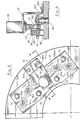
- FIG. 1 is a bottom plan view of a portion of the configured surface of a stationary sorting head embodying the present invention;
- FIG. 2 is an enlarged section taken generally along line 2-2 in FIG. 1;
- FIG. 3 is a top plan view of the same portion of the sorting head shown in FIG. 1; and
- FIG. 4 is a section taken generally along line 4-4 in FIG. 3.
- While the invention will be described in connection with certain preferred embodiments, it will be understood that it is not intended to limit the invention to these particular embodiments. On the contrary, it is intended to cover all alternatives, modifications and equivalent arrangements as may be included within the scope of the invention as defined by the appended claims.
- Turning now to the drawings and referring to FIG. 1, there is shown a portion of a sorting head for use in a disc-type coin sorter of the type described, for example, in Ristvedt U.S. Patent No. 4,681,128, issued July 21, 1987. As is well known in the coin-sorting art, a disc-type coin sorter typically has a motor-driven disc with a resilient pad on the upper surface of the disc. This disc is rotated beneath a stationary sorting head having a configured lower surface for manipulating and sorting mixed denominations of coins as they are moved circumferentially beneath the head by the rotating disc. The stationary head has a central opening through which coins are fed from a hopper on the top of the head onto the central portion of the resilient surface of the rotating disc. The rotation of the disc causes the coins to move outwardly across the surface of the disc into the space between the stationary head and the rotating disc.
- After the coins have entered the space between the stationary head and the rotating disc, the configured surface on the underside of the head arranges the coins in a single row and a single layer. Various configurations are known in the art for achieving this "queueing" of the coins, and one example of a suitable coin-queueing arrangement is described in the aforementioned Ristvedt U.S. Patent No. 4,681,128. Another example is described in Raterman U.S. Patent No. 4,570,655 issued February 18, 1986.
- After queueing, the single row and single layer of coins are led into a region of the space between the rotating disc and the stationary head where the coins are pressed by the bottom surface of the stationary head into the resilient surface of the rotating disc, so that the coins are held in a fixed radial position by the pressure applied to opposite surfaces of the coin. Normally, the coins are positioned with either the outer edges or the inner edges of the coins of all denominations at a constant radius from the axis of rotation of the disc. The coins continue to move circumferentially around the sorting head as long as the disc continues to rotate.
- In the particular embodiment of the present invention illustrated in FIG. 1, the sorting head aligns the coins of all denominations with their outer edges located at a common radius illustrated by the broken-
line arc 20. As the coins are rotated with their outer edges following thearc 20, the coins of all denominations enter arecess 21 having anouter edge 22 which forms an outer guide surface facing inwardly for engaging the outer edges of the aligned coins. Thisguide surface 22 spirals inwardly so that it progressively moves the engaged coins radially inwardly as the coins move circumferentially along the guide surface. As can be seen more clearly in the sectional view in FIG. 2, theouter guide surface 22 is tapered at an angle of less than 45° from vertical, for reasons which will be described in more detail below. - As the coins are advanced along the
guide surface 22, the inner edges of the coins of each different denomination engage one of a series of circumferentially spacedguide members guide surface 22. As will be described in more detail below, theguide members 23a-23f force the coins of different denominations outwardly past theguide surface 22 at different circumferential positions along the length of theguide surface 22. - The illustrative sorter is designed for sorting the six coin denominations of United States currency. Thus, the largest of those six coins (the half dollars) engage the
first guide member 23a, which is spaced further away from theguide surface 22 than any of the succeedingguide members 23b-23f. The outer surface of theguide member 23a follows a constant radius R1 from the axis of rotation of the rotating disc, while the opposed portion of theguide surface 22 has a progressively decreasing radius as measured from the axis of rotation. Consequently, the radial distance between theguide surface 22 and the outer surface of theguide member 23a decreases progressively in the direction of coin movement as theguide surface 22 converges toward the guide surface formed by themember 23a. More specifically, this radial distance is at least as great as the diameter of the half dollar at the entry end of theguide member 23a, and is substantially less than the diameter of the half dollar at the exit end of theguide member 23a. Thus, as a half dollar traverses theguide member 23a, the outer edge of the half dollar is forced outwardly past theguide surface 22, as illustrated by the two half dollars shown in broken lines in FIG. 1. The taper of theguide surface 22 enables the coins to pass thereunder. - The
surface 24 of the sorting head outboard of the guidingsurface 22 is a portion of the lowermost surface of the head. That is, this portion of the head surface is located closer to the top surface of the resilient pad on the spacing between thesurface 24 and the uppermost surface of the disc is 0,0000254 m (0.001 inch) to 0,0000762 m (0.003 inch). Consequently, when a coin is forced past theguide surface 22, that coin is pressed firmly between thesurface 24 of the sorting head and the resilient surface on the top of the rotating disc, thereby holding that coin in a fixed radial position as it continues to be moved circumferentially by the rotation of the disc. In the case of the half dollar, this fixed radial position is determined by theguide member 23a, i.e., every half dollar is positioned with its inner edge at the radius R1 defined by the outer surface of theguide member 23a. As will be apparent from the ensuing description, the half dollars continue to travel circumferentially with their inner edges at this radius R1 until they are exited from the sorting head. - As can be seen in FIG. 1, the distance between the guiding
surface 22 and the outer surfaces ofsuccessive guide members successive guide members 23b-23f. Specifically, the dollar coins engage theguide member 23b, the quarters engage the guide member 23c, the nickels engage theguide member 23d, the pennies engage theguide member 23e, and the dimes engage theguide member 23f. In each case, the guide member has the same effect described above for theguide member 23a on the half dollar, i.e., the guide member forces the corresponding coin engaged thereby outwardly past theguide surface 22 so that that particular denomination of coin continues to be rotated with its inner edge held at a constant radial position defined by the radius of the outer surface of the corresponding guide member. - As can also be seen in FIG. 1, the outer surfaces of the
successive guide members 23b-23f are located at different radial distances R2, R3, R4, R5 and R6 from the axis of rotation of the disc, so that the inner edges of each denomination of coin are located at a unique radial position. Thereby permits subsequent discrimination of coins of different denominations according to the radial positions of the inner edges of the coins. For example, the inner edges of the dollar coins are located at radius R2, which is spaced inwardly from the radius R1 of the inner edges of the half dollars. Similarly, the inner edges of the quarters are located at radius R3, the inner edges of the nickels are located at radius R4, the inner edges of the pennies are located at radius R5, and the inner edges of the dimes are located at radius R6. These different radii preferably differ from each other by at least 0,0127 m (0.50 inch), to facilitate discrimination among the different coin denominations. For example, in one particular embodiment, the radii R1-R6 have dimensions of 0,10795 m; 0,10668 m; 0,10541 m; 0,10414 m; 0,10287 m; 0,1016 m (4.250, 4.200, 4.150, 4.100, 4.050 and 4.000 inches), respectively. - It will be noted that the outer surface of each
successive guide member 23a-23f is spaced radially inwardly from the radius of the outer surface of all preceding guide members, so that any coin which engages a preceding guide member clears all succeeding guide members. For example, the half dollars engage theguide member 23a which positions the half dollars engage theguide member 23a which positions the inner edge of that particular coin denomination at a radius R1, and then the half dollars remain with their inner edges at the radius R1 and thus clear all succeedingguide members 23b-23f. Also, the exit end of the outer surface of each guide member is spaced from theouter guide surface 22 by a distance greater than the diameter of the next smaller coin. Each guide member, therefore, engages the coins of only one denomination. - As the coins continue to be carried by the rotating disc, after they have all been moved outwardly past the
guide surface 22, they are ultimately discharged from the space between the rotating disc and the sorting head by providing an inwardly spiraling outer edge on the sorting head. As the outer edge of the head spirals inwardly, it releases the coins of different denominations successively at different circumferential locations according to the radial positions of the inner edges of the coins. Because the half dollars have their inner edges at the radially outermost positions, the half dollars exit first, then the dollars, then the quarters and so on. This discharge arrangement is not shown in the drawings, because it is the same arrangement shown in the aforementioned Ristvedt U.S. Patent No. 4,681,128. - It is often desirable for coin sorters to have what is commonly referred to as a "bagstop" feature. This means that the sorter stops the discharge of coins after a preselected number of coins of a selected denomination have been discharged into a coin bag or box. Most coin sorters have automatic counters for each different denomination of coins. In the illustrative sorting head shown in FIG. 1, the
guide members 23a-23f may be used as the sensing means for the counters by generating an electrical signal each time a coin engages one of theguide members 23a-23f. This is accomplished by insulating each of theguide members 23a-23f from the sorting head by means of an insulating sleeve 30 (FIGS. 2 and 4) and applying an electrical voltage across theguide member 23 and the sorting head. The electrical circuit remains open except when the guide member is physically engaged by a coin, which of course is also in contact with the sorting head. Thus, whenever a coin engages theguide member 23, an electrical signal is supplied to one of the corresponding counter which accumulate numbers representing the number of coins of each denomination that have contacted therespective guide members - After a preselected number of coins of a selected denomination have been counted, the discharge of additional coins is stopped by retracting all the
guide members 23a-23f upwardly into the sorting head so that the six guide members are all withdrawn from the coin path. As long as the guide members are in this retracted position, the coins of all denominations will simply follow theguide surface 22 and be returned to the central portion of the sorting head for another cycle. The mechanism for retracting theguide members 23a-23f is illustrated in FIGS. 3 and 4. All sixguide members 23a-23f are fastened to a single mountingplate 31, which in turn is connected to asolenoid 32 by means of apull rod 33. In the particular arrangement illustrated, each guide member is provided with a circumferential groove for receiving a lockingwasher 34 above the mountingplate 31, and the pull rod is connected to the core of the solenoid by means of a locking pin. Thesolenoid 32 is supported on a mountingbracket 35 attached to the top surface of the sorting head by a pair ofscrews 35a and 35b. - The
guide members 23a-23f are normally held in their lowered, advanced positions shown in FIGS. 2 and 4, for engaging the coins passing thereby. This advanced position of the guide members is determined by astop 36 which is mounted on the top surface of the sorting head for engaging the lower surface of the mountingplate 31. The mountingplate 31 is made of an insulating material so that it does not provide a short circuit between the guide members and the sorting head. On top of the mountingplate 31, fourslide rods 37 extend upwardly therefrom, and each rod is surrounded by areturn spring 38 for urging the mountingplate 31, downwardly against thestop 36. Thereturn spring 38 is held in place by means of awasher 39 and a lockingwasher 40 received in a circumferential groove in theslide rod 37. - When a preselected number of coins of a given denomination have been counted, the
solenoid 32 is energized by the counter which has been receiving signals from theguide member 23 corresponding to that particular coin denomination. Energization of thesolenoid 32 raises the mountingplate 31 upwardly against the biasing force of thespring 38. As already explained, this upward movement of theplate 31 retracts theguide members 23a-23f upwardly into the sorting head, thereby removing the guide members from the path of the coins being carried on the surface of the rotating disc. The solenoid remains energized, holding theplate 31 in the raised position, until it is desired to re-start the sorting operation. This gives the operator time to remove the bag or box of coins containing the desired number of coins of the selected denomination, and to replace that full bag or box with an empty receptacle. The operator then activates a switch which deenergizes thesolenoid 32, enabling thereturn spring 38 to return theplate 31 to its advanced position against thestop member 36, thereby returning theguide members 23a-23f to their operative, lowered positions. - In order to prevent additional coins from entering the queuing region of the sorting head while the
solenoid 32 is energized, it is preferred to provide a solenoid-operated coin deflector at the entry to the queuing region. Such solenoid-operated deflectors are known in prior art sorters, such as those described, for example, in Raterman U.S. Patent 4,570,655 issued February 18, 1986, and in Ristvedt published British Patent Application No. 2,193,364, published February 2, 1988. - Instead of initially aligning the coins with their outer edges at a common radial position, the coins may be initially aligned with their inner edges at a common radial position. The coins are then advanced so that the inner edges of the coins of all denominations follow an outwardly facing guide surface which spirals outwardly. The
guide members 23a-23f are then located outboard of the inner guide surface, so that the inside surfaces of the guide members form outer guide surfaces facing the spiral inner guide surface. This arrangement causes the inner edges of the coins to be forced inwardly over the inner guide surface so that the inner edges of the coins of each denomination are positioned at a unique radius, different from the radial locations of the outer edges of the coins of all other denominations. This permits discrimination among the coins of different denominations according to the radial positions of the inner edges of the coins in the same manner described above. With this arrangement, the coins are all discharged at a common circumferential location (rather than being recycled to the central region of the sorter) when the guide members are retracted.
Claims (3)
- A disc-type coin sorter having a rotatable disc with a resilient top surface and a stationary sorting head positioned above said disc with the lowermost surface of the sorting head only slightly spaced from the resilient top surface of the disc, said sorting head havingcoin queuing means for arranging coins of mixed denominations in a single row and a single layer with selected edges of the coins aligned at a common radial position,a first guide surface (22) for engaging selected edges of the aligned coins and progressively moving the engaged coins radially as the coins move circumferentially along said first guide surface (22),a plurality of second guide surfaces (23a-f) spaced radially from, and facing toward, said first guide surface (22) for forcing coins of selected denominations under and past said first guide surface (22) at selected circumferential locations,the distance between said first and second guide surfaces (22, 23a-f) progressively decreasing in the circumferential direction so that coins of progressively smaller diameter are engaged by successive second guide surfaces (23a-f), andsaid plurality of second guide surfaces (23a-f) being located at different radial distances (R1-R6), from said axis of rotation so that the edges of each denomination of coin forced past said first guide surfaces (22) are located at a unique radial position, thereby permitting discrimination among coins of different denominations according to the radial positions of the edges of said coins,characterised in that each of said elongated second guide surfaces (23a-f) is elongated in the direction of coin movement and has a substantially constant radius from the axis of rotation of said disc so that the coins engaged thereby are not moved radially.
- The coin sorter of claim 1, characterised in that it includes means (31, 32, 33) for retracting said second guide surfaces (23a-f) from the path of the coins on said disc so that the coins can be recycled in response to the detection of a selected condition.
- The coin sorter of claim 1 or 2, characterised in that it includes counting means connected to said second guide surfaces (23a-f) for sensing the engagement of each separate coin with one of said second guide surfaces (23a-f).
Applications Claiming Priority (3)
| Application Number | Priority Date | Filing Date | Title |
|---|---|---|---|
| US432625 | 1982-10-04 | ||
| US07/432,625 US5026320A (en) | 1989-11-06 | 1989-11-06 | Disc-type coin sorter with retractable guide surfaces |
| PCT/US1990/006676 WO1991006927A1 (en) | 1989-11-06 | 1990-10-31 | Disc-type coin sorter with retractable guide surfaces |
Publications (3)
| Publication Number | Publication Date |
|---|---|
| EP0452485A1 EP0452485A1 (en) | 1991-10-23 |
| EP0452485A4 EP0452485A4 (en) | 1994-04-20 |
| EP0452485B1 true EP0452485B1 (en) | 1996-12-11 |
Family
ID=23716928
Family Applications (1)
| Application Number | Title | Priority Date | Filing Date |
|---|---|---|---|
| EP91901042A Expired - Lifetime EP0452485B1 (en) | 1989-11-06 | 1990-10-31 | Disc-type coin sorter with retractable guide surfaces |
Country Status (7)
| Country | Link |
|---|---|
| US (1) | US5026320A (en) |
| EP (1) | EP0452485B1 (en) |
| JP (1) | JP3102883B2 (en) |
| AU (1) | AU635602B2 (en) |
| CA (1) | CA2044262C (en) |
| DE (1) | DE69029386D1 (en) |
| WO (1) | WO1991006927A1 (en) |
Families Citing this family (49)
| Publication number | Priority date | Publication date | Assignee | Title |
|---|---|---|---|---|
| US4966570A (en) * | 1987-07-30 | 1990-10-30 | Ristvedt Victor G | Coin sorting apparatus for sorting coins of selected denominations |
| US5141472A (en) * | 1990-10-30 | 1992-08-25 | Cummins-Allison Corp. | Disc-type coin sorter with adjustable gaging device |
| US5205780A (en) * | 1991-04-29 | 1993-04-27 | Cummins-Allison Corporation | Disc-type coin sorter with eccentric feed |
| US5163866A (en) * | 1991-04-29 | 1992-11-17 | Cummins-Allison Corp. | Disc-type coin sorter with multiple-path queuing |
| US5163867A (en) * | 1991-05-15 | 1992-11-17 | Cummins-Allison Corp. | Disc-type coin sorter with multiple-path queuing |
| US5145455A (en) * | 1991-05-15 | 1992-09-08 | Cummins-Allison Corp. | Wave-type coin sorter |
| WO1992022044A1 (en) * | 1991-06-03 | 1992-12-10 | Cummins-Allison Corp. | Disc-type coin sorter |
| US5382191A (en) * | 1993-03-26 | 1995-01-17 | Cummins-Allison Corp. | Coin queuing device and power rail sorter |
| US5372542A (en) * | 1993-07-09 | 1994-12-13 | Cummins-Allison Corp. | Disc coin sorter with improved exit channel |
| US5401211A (en) * | 1993-08-05 | 1995-03-28 | Cummins-Allison Corp. | Disc coin sorter with positive guide wall between exit channels |
| US5468182A (en) * | 1993-08-05 | 1995-11-21 | Cummins-Allison Corp. | Disc-type coin sorter with adjustable targeting inserts |
| US5514034A (en) * | 1993-09-28 | 1996-05-07 | Cummins-Allison Corp. | Apparatus and method for terminating coin sorting using pressureless exit channels and immediate stopping |
| US5370575A (en) * | 1994-01-06 | 1994-12-06 | Cummins-Allison Corp. | Coin sorting mechanism |
| US5501631A (en) * | 1994-01-06 | 1996-03-26 | Cummins-Allison Corp. | Coin handling device with an improved lubrication system |
| US5425669A (en) * | 1994-01-07 | 1995-06-20 | Cummins-Allison Corp. | Coin queuing and sorting arrangement |
| US5607351A (en) * | 1994-11-10 | 1997-03-04 | Automated Currency Instruments, Inc. | Coin counting machine |
| US6363164B1 (en) | 1996-05-13 | 2002-03-26 | Cummins-Allison Corp. | Automated document processing system using full image scanning |
| US6748101B1 (en) | 1995-05-02 | 2004-06-08 | Cummins-Allison Corp. | Automatic currency processing system |
| US5865673A (en) * | 1996-01-11 | 1999-02-02 | Cummins-Allison Corp. | Coin sorter |
| US8950566B2 (en) | 1996-05-13 | 2015-02-10 | Cummins Allison Corp. | Apparatus, system and method for coin exchange |
| US5997395A (en) * | 1998-03-17 | 1999-12-07 | Cummins-Allison Corp. | High speed coin sorter having a reduced size |
| US8701857B2 (en) | 2000-02-11 | 2014-04-22 | Cummins-Allison Corp. | System and method for processing currency bills and tickets |
| US6896118B2 (en) | 2002-01-10 | 2005-05-24 | Cummins-Allison Corp. | Coin redemption system |
| US7743902B2 (en) | 2002-03-11 | 2010-06-29 | Cummins-Allison Corp. | Optical coin discrimination sensor and coin processing system using the same |
| US6892871B2 (en) | 2002-03-11 | 2005-05-17 | Cummins-Allison Corp. | Sensor and method for discriminating coins of varied composition, thickness, and diameter |
| US6755730B2 (en) | 2002-03-11 | 2004-06-29 | Cummins-Allison Corp. | Disc-type coin processing device having improved coin discrimination system |
| AU2003239234A1 (en) | 2002-06-14 | 2003-12-31 | Cummins-Allison Corp. | Coin redemption machine having gravity feed coin input tray and foreign object detection system |
| US8171567B1 (en) | 2002-09-04 | 2012-05-01 | Tracer Detection Technology Corp. | Authentication method and system |
| US8393455B2 (en) | 2003-03-12 | 2013-03-12 | Cummins-Allison Corp. | Coin processing device having a moveable coin receptacle station |
| US7783349B2 (en) * | 2006-04-10 | 2010-08-24 | Cardiac Pacemakers, Inc. | System and method for closed-loop neural stimulation |
| US9934640B2 (en) | 2004-09-15 | 2018-04-03 | Cummins-Allison Corp. | System, method and apparatus for repurposing currency |
| US8523641B2 (en) | 2004-09-15 | 2013-09-03 | Cummins-Allison Corp. | System, method and apparatus for automatically filling a coin cassette |
| US8602200B2 (en) | 2005-02-10 | 2013-12-10 | Cummins-Allison Corp. | Method and apparatus for varying coin-processing machine receptacle limits |
| WO2007044570A2 (en) | 2005-10-05 | 2007-04-19 | Cummins-Allison Corp. | Currency processing system with fitness detection |
| US7980378B2 (en) | 2006-03-23 | 2011-07-19 | Cummins-Allison Corporation | Systems, apparatus, and methods for currency processing control and redemption |
| US8042732B2 (en) | 2008-03-25 | 2011-10-25 | Cummins-Allison Corp. | Self service coin redemption card printer-dispenser |
| US20130004490A1 (en) | 2009-12-14 | 2013-01-03 | The United States of America, as represented by the Secretary, Department | Delivery of transthyretin across the blood-brain barrier as a treatment for alzheimer's disease |
| US8545295B2 (en) | 2010-12-17 | 2013-10-01 | Cummins-Allison Corp. | Coin processing systems, methods and devices |
| US9092924B1 (en) | 2012-08-31 | 2015-07-28 | Cummins-Allison Corp. | Disk-type coin processing unit with angled sorting head |
| US10685523B1 (en) | 2014-07-09 | 2020-06-16 | Cummins-Allison Corp. | Systems, methods and devices for processing batches of coins utilizing coin imaging sensor assemblies |
| US9501885B1 (en) | 2014-07-09 | 2016-11-22 | Cummins-Allison Corp. | Systems, methods and devices for processing coins utilizing near-normal and high-angle of incidence lighting |
| US9916713B1 (en) | 2014-07-09 | 2018-03-13 | Cummins-Allison Corp. | Systems, methods and devices for processing coins utilizing normal or near-normal and/or high-angle of incidence lighting |
| US9508208B1 (en) | 2014-07-25 | 2016-11-29 | Cummins Allison Corp. | Systems, methods and devices for processing coins with linear array of coin imaging sensors |
| US9430893B1 (en) | 2014-08-06 | 2016-08-30 | Cummins-Allison Corp. | Systems, methods and devices for managing rejected coins during coin processing |
| US10089812B1 (en) | 2014-11-11 | 2018-10-02 | Cummins-Allison Corp. | Systems, methods and devices for processing coins utilizing a multi-material coin sorting disk |
| US9875593B1 (en) | 2015-08-07 | 2018-01-23 | Cummins-Allison Corp. | Systems, methods and devices for coin processing and coin recycling |
| US10679449B2 (en) | 2016-10-18 | 2020-06-09 | Cummins-Allison Corp. | Coin sorting head and coin processing system using the same |
| US10181234B2 (en) | 2016-10-18 | 2019-01-15 | Cummins-Allison Corp. | Coin sorting head and coin processing system using the same |
| CA3066598A1 (en) | 2019-01-04 | 2020-07-04 | Cummins-Allison Corp. | Coin pad for coin processing system |
Family Cites Families (6)
| Publication number | Priority date | Publication date | Assignee | Title |
|---|---|---|---|---|
| US4564036A (en) * | 1983-09-15 | 1986-01-14 | Ristvedt-Johnson, Inc. | Coin sorting system with controllable stop |
| US4570655A (en) * | 1983-09-28 | 1986-02-18 | Raterman Donald E | Apparatus and method for terminating coin sorting |
| US4607649A (en) * | 1983-12-21 | 1986-08-26 | Brandt, Inc. | Coin sorter |
| US4681128A (en) * | 1986-06-23 | 1987-07-21 | Ristvedt Victor G | Coin sorter |
| US4863414A (en) * | 1986-06-23 | 1989-09-05 | Ristvedt Victor G | Coin sorter |
| US5022889A (en) * | 1986-06-23 | 1991-06-11 | Ristvedt Victor G | Coin sorter |
-
1989
- 1989-11-06 US US07/432,625 patent/US5026320A/en not_active Expired - Lifetime
-
1990
- 1990-10-31 AU AU69570/91A patent/AU635602B2/en not_active Ceased
- 1990-10-31 CA CA002044262A patent/CA2044262C/en not_active Expired - Fee Related
- 1990-10-31 JP JP03501479A patent/JP3102883B2/en not_active Expired - Fee Related
- 1990-10-31 EP EP91901042A patent/EP0452485B1/en not_active Expired - Lifetime
- 1990-10-31 WO PCT/US1990/006676 patent/WO1991006927A1/en active IP Right Grant
- 1990-10-31 DE DE69029386T patent/DE69029386D1/en not_active Expired - Lifetime
Also Published As
| Publication number | Publication date |
|---|---|
| WO1991006927A1 (en) | 1991-05-16 |
| CA2044262C (en) | 1997-02-04 |
| AU635602B2 (en) | 1993-03-25 |
| CA2044262A1 (en) | 1991-05-07 |
| AU6957091A (en) | 1991-05-31 |
| DE69029386D1 (en) | 1997-01-23 |
| EP0452485A4 (en) | 1994-04-20 |
| EP0452485A1 (en) | 1991-10-23 |
| US5026320A (en) | 1991-06-25 |
| JP3102883B2 (en) | 2000-10-23 |
| JPH05504641A (en) | 1993-07-15 |
Similar Documents
| Publication | Publication Date | Title |
|---|---|---|
| EP0452485B1 (en) | Disc-type coin sorter with retractable guide surfaces | |
| US4275751A (en) | Coin sorter with expanded capability | |
| AU675571B2 (en) | Coin sorter with wall between exit channels | |
| AU660244B2 (en) | Coin sorter with automatic bag-switching or stopping | |
| US5468182A (en) | Disc-type coin sorter with adjustable targeting inserts | |
| EP0557428B1 (en) | Coin sorting mechanism | |
| EP0442441B1 (en) | Coin sorter with automatic bagswitching | |
| EP0360532B1 (en) | Coin sorting mechanism | |
| US7188720B2 (en) | Disc-type coin processing device having improved coin discrimination system | |
| US4111216A (en) | Centrifugal coin sorter | |
| US5542881A (en) | Coin sorting mechanism having dual recycle channels | |
| US5141472A (en) | Disc-type coin sorter with adjustable gaging device | |
| EP0387795A2 (en) | Coin sorting mechanism | |
| EP0149906A2 (en) | A coin sorter | |
| US5607351A (en) | Coin counting machine | |
| EP0285240B1 (en) | Coin sorting mechanism |
Legal Events
| Date | Code | Title | Description |
|---|---|---|---|
| PUAI | Public reference made under article 153(3) epc to a published international application that has entered the european phase |
Free format text: ORIGINAL CODE: 0009012 |
|
| AK | Designated contracting states |
Kind code of ref document: A1 Designated state(s): DE FR GB IT NL |
|
| 17P | Request for examination filed |
Effective date: 19911115 |
|
| A4 | Supplementary search report drawn up and despatched |
Effective date: 19940303 |
|
| AK | Designated contracting states |
Kind code of ref document: A4 Designated state(s): DE FR GB IT NL |
|
| 17Q | First examination report despatched |
Effective date: 19950719 |
|
| GRAG | Despatch of communication of intention to grant |
Free format text: ORIGINAL CODE: EPIDOS AGRA |
|
| GRAH | Despatch of communication of intention to grant a patent |
Free format text: ORIGINAL CODE: EPIDOS IGRA |
|
| GRAH | Despatch of communication of intention to grant a patent |
Free format text: ORIGINAL CODE: EPIDOS IGRA |
|
| GRAA | (expected) grant |
Free format text: ORIGINAL CODE: 0009210 |
|
| AK | Designated contracting states |
Kind code of ref document: B1 Designated state(s): DE FR GB IT NL |
|
| PG25 | Lapsed in a contracting state [announced via postgrant information from national office to epo] |
Ref country code: IT Free format text: LAPSE BECAUSE OF FAILURE TO SUBMIT A TRANSLATION OF THE DESCRIPTION OR TO PAY THE FEE WITHIN THE PRE;WARNING: LAPSES OF ITALIAN PATENTS WITH EFFECTIVE DATE BEFORE 2007 MAY HAVE OCCURRED AT ANY TIME BEFORE 2007. THE CORRECT EFFECTIVE DATE MAY BE DIFFERENT FROM THE ONE RECORDED.SCRIBED TIME-LIMIT Effective date: 19961211 Ref country code: FR Effective date: 19961211 Ref country code: NL Free format text: LAPSE BECAUSE OF FAILURE TO SUBMIT A TRANSLATION OF THE DESCRIPTION OR TO PAY THE FEE WITHIN THE PRESCRIBED TIME-LIMIT Effective date: 19961211 |
|
| REF | Corresponds to: |
Ref document number: 69029386 Country of ref document: DE Date of ref document: 19970123 |
|
| PG25 | Lapsed in a contracting state [announced via postgrant information from national office to epo] |
Ref country code: DE Effective date: 19970312 |
|
| NLV1 | Nl: lapsed or annulled due to failure to fulfill the requirements of art. 29p and 29m of the patents act | ||
| EN | Fr: translation not filed | ||
| PLBE | No opposition filed within time limit |
Free format text: ORIGINAL CODE: 0009261 |
|
| STAA | Information on the status of an ep patent application or granted ep patent |
Free format text: STATUS: NO OPPOSITION FILED WITHIN TIME LIMIT |
|
| 26N | No opposition filed | ||
| REG | Reference to a national code |
Ref country code: GB Ref legal event code: IF02 |
|
| PGFP | Annual fee paid to national office [announced via postgrant information from national office to epo] |
Ref country code: GB Payment date: 20021030 Year of fee payment: 13 |
|
| PG25 | Lapsed in a contracting state [announced via postgrant information from national office to epo] |
Ref country code: GB Free format text: LAPSE BECAUSE OF NON-PAYMENT OF DUE FEES Effective date: 20031031 |
|
| GBPC | Gb: european patent ceased through non-payment of renewal fee |
Effective date: 20031031 |