US5607351A - Coin counting machine - Google Patents
Coin counting machine Download PDFInfo
- Publication number
- US5607351A US5607351A US08/337,666 US33766694A US5607351A US 5607351 A US5607351 A US 5607351A US 33766694 A US33766694 A US 33766694A US 5607351 A US5607351 A US 5607351A
- Authority
- US
- United States
- Prior art keywords
- coin
- coins
- rotating disk
- disk assembly
- disk
- Prior art date
- Legal status (The legal status is an assumption and is not a legal conclusion. Google has not performed a legal analysis and makes no representation as to the accuracy of the status listed.)
- Expired - Lifetime
Links
Images


Classifications
-
- G—PHYSICS
- G07—CHECKING-DEVICES
- G07D—HANDLING OF COINS OR VALUABLE PAPERS, e.g. TESTING, SORTING BY DENOMINATIONS, COUNTING, DISPENSING, CHANGING OR DEPOSITING
- G07D9/00—Counting coins; Handling of coins not provided for in the other groups of this subclass
- G07D9/008—Feeding coins from bulk
-
- G—PHYSICS
- G07—CHECKING-DEVICES
- G07D—HANDLING OF COINS OR VALUABLE PAPERS, e.g. TESTING, SORTING BY DENOMINATIONS, COUNTING, DISPENSING, CHANGING OR DEPOSITING
- G07D3/00—Sorting a mixed bulk of coins into denominations
- G07D3/16—Sorting a mixed bulk of coins into denominations in combination with coin-counting
Definitions
- the present invention relates to coin and token counting machines for use in multi-denominational transactions requiring speed and accuracy.
- U.S. Pat. No. 4,570,655 to Raterman teaches a coin sorting apparatus similar to that of Rasmissen utilizing the rotating disk assembly with grooved surfaces for transporting coins in outward radial directions according to their size. Exit recesses equidistant from each other about the periphery of the disk provide a means to separate and sort the coins. A sensory device is located by each recess which, when a pre-determined number of coins are sorted, automatically signals a bridge guide and a diameter guide which redirect the rotating coins and terminate the sorting process for each respective denomination.
- U.S. Pat. No. 4,564,036 to Risvedt discloses a similar apparatus whereby sensors count coins separated according to size and when a predetermined number is sorted the remaining coins are redirected back to the center of the disk.
- U.S. Pat. No. 4,921,463 to Primdahl et. al. discloses a rotating disk assembly wherein the coins are sorted as they are ejected through equidistantly-spaced recesses in the periphery of the lower disk which are counted by a sensor. Once a predetermined number is reached, a brake mechanism is operatively connected to the sensor through an electromagnetic actuating assembly and shuts the sorting process off when that number of coins is sorted.
- U.S. Pat. No. 4,098,280 and 4,444,212 both to Risvedt et. al. disclose rotating disk assemblies with a flexible surface and an annular guide plate suspension thereon to direct radially moving coins towards the periphery. Counters calibrated to the denomination at each exit allow for the determination of the number of coins of each denomination.
- U.S. Pat. Nos. 4,531,531 and 4,549,561 to Johnson et. al. discloses a coin sorting apparatus comprising a rotating disk which, like the rest of the prior art, separates the coins using grooves and recesses which direct the coins in their radial movement outward due to centrifugal force to designated exit portals which sort them according to size.
- Coin counters may be of the type employing light, radiation, magnetic or other forms of conventional sensing devices to verify each different sized coin. The coins move single file about the periphery until each one exits through an appropriately sized recess.
- the present invention is a digitally controlled coin/token counting system that permits the fast and accurate valuation of a mixed aggregate of multi-denominational coins.
- a rotating disk containing integral radial guides centrifugally moves the coins from a centrally located coin deposit tray outward until the coins are flung uncontrollably off the disk and downward into a temporary storage bin.
- the value of the coin is determined by an electronic sensor disposed within the guide that relays this information to a microprocessor-based programmable logic controller which records and qualifies the coins passing thereto. After completing the count of a given batch, the coins may be returned to the customer if the determined value is challenged or can be sorted and accounted for as a complete transaction.
- FIG. 1 is an overall side view of the coin counting machine of the present invention showing a cross-sectional view of the rotating disk assembly.
- FIG. 2 is an overhead, isolated view of the grooved disk embodiment of the rotating disk assembly of the present invention.
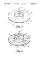
- FIG. 3 is an overhead, isolated view of the intact wedge embodiment of the rotating disk assembly of the present invention.
- FIG. 4 is an isolated transparent view of the rotating disk assembly of the present invention.
- FIG. 5 is an isolated transparent view of the rotating disk assembly of the present invention showing disbursement of coins during operation.
- FIG. 6 is an overhead, cross-sectional view of the rotating disk assembly showing the sensor locations, wedges and jam clearing means.
- FIG. 7 is a cross-sectional side view of the rotating disk assembly of the present invention showing the sensors and jam clearing means.
- FIG. 8 is a schematic representation of the sensor counting system of the present invention.
- the coin counting apparatus of the present invention enables one to quickly count and value a mixed assortment of coins or tokens prior to sorting and allows for an immediate and simple recount if necessary.
- the coin counting apparatus is comprised of a cabinet for containment of the component parts (1), a rotating disk assembly (2), an electronic sensor device operatively attached thereto (4), a microprocessor logic control unit (6) for assimilation and analysis of the data from the sensor and a deposit bin for eventual collection and storage of the counted coins (7).
- Each multi-denomination or single denominational aggregate of coins that is collected may be packaged and marked as to their value using a bar coding device (not shown) or can be returned to the counting device for verification if so desired.
- the rotating disk assembly can be comprised of several different embodiments.
- the most simplistic design for the rotating disk assembly can consist of one lower disk (8) with a centrally disposed coin deposit tray (10) a motorized drive shaft (12) and equally spaced guides or channels (14) that are partially grooved or recessed into the upper surface of the disk (16) and are approximately two (2) inches wide and one-eighth (1/8) of an inch deep.
- the grooves (14) run from the periphery of the disk (8) under and into the space (18) formed within the coin deposit tray by means of contiguous portals (20) in the walls of the tray (10).
- the disk assembly can comprise a solid lower disk (8) with no grooves but with equally sized and spaced pie-shaped wedges (22) superimposed thereon.
- the wedges correspond to the top surface (16) of the integral disk in FIG. 2 and the placement of the wedges forms passageways or guides for the coins deposited in the coin collection tray to be moved radially outward through the application of centrifugal force by spinning the rotating disk assembly.
- the preferred embodiment of the present invention comprises a three-layered rotating disk assembly (2) consisting of a lower disk (8, not shown), a series of equally sized, equidistantly spaced wedges (22) overlapping the lower disks periphery and an upper disk (24) that extends beyond the periphery of the lower disk (8) and is contiguous with the peripheral edges of the wedges (22).
- the wedges (22) so placed form passageways or guides (26) that functionally correspond to the grooves (14) in FIG. 2 and connect the central area (18) of the coin deposit tray (10) with the outer perimeter of the disks.
- An alternative to this embodiment would be a two-layered disk assembly in which the wedges (22) are removed and the lower disk is grooved as in FIG. 2 so that the grooves provide the directional functionality served by the passageways (14) formed by the equally spaced wedges (22). A larger, upper disk (24) is then superimposed over the lower disk (8).
- the size of the passageways or grooves is not of great importance but preferably should be about two (2) inches in width and one-eight (1/8) of an inch in depth so as to be able to disperse and register any sized coin up to a five dollar gaming piece.
- the rotating disk assembly (2) of FIG. 3 is shown in phantom whereby the lower disk (8) and upper disk (24) are aligned so as to sandwich a number of the pie-shaped wedges (22) therebetween.
- the peripheral edge of the upper disk (24) is aligned with that of the pie-shaped wedges (22) and this extends over the circumference of the lower disk (8).
- the symmetrical arrangement of the wedges (22) about the periphery of the upper disk (24) and coin deposit tray (10) which is superimposed upon the wedges apices (15) provides channels or guides (14) through which the coins may pass when pushed outward by the centrifugal force created by the spinning motion of the rotating disk assembly (2).
- the wedges (22) and the periphery of the upper disk (24) extend over beyond the circumference or periphery of the lower disk (8). This, as before, creates a gap (26) which results in the coins immediately falling down prior to reaching the far edges of the disk assembly (2) created by the circumference of the upper disk (24). This allows for the construction of containment walls (not shown) immediately proximate to the upper disk edge and maximizes space efficiency while lowering constructions costs. There is no specific requirement as to the size of the disks themselves which would only depend on the size of the machine which in turn is dictated by space restrictions and the volume of coins to the counted. Generally, disks of one to two feet in diameter is sufficient.
- the rotating disk assembly (2) is again shown in phantom with the coins (28) placed as they would be during a counting procedure.
- the coins (28) that are dumped into the coin feed tray (10) are urged outwards against the wall of the tray (arrow A) due to centrifugal forces exerted against them from the spinning motion of the disk assembly (2) when the motor (not shown) attached to the drive shaft (12) is turned on.
- the constant revolution of the disk (8,24) and deposit tray (10) continually move the coins about in the tray and result in the eventual placement of each coin at the entrance (22) to one of the grooves (14) of the lower disk (8).
- the rotating disk assembly 2 of the preferred embodiment of the present invention (FIGS. 4 and 5) is viewed in greater detail showing the additional component parts.
- coins to be counted are initially placed within the centrally disposed coin deposit tray (10) which is connected at its base with either the radially extending grooves constructed within the top (16) of the lower disk (8) or as in this case passageways or guides (14) formed between the lateral edges of the pie-shaped wedges (22) so that upon rotation of the disk assembly (2), coins deposited in the feed tray (10) exit through the entrance (20) to the guides (14) and move in an outward radial direction through the passageways or grooves (14) due to the exertion of centrifugal forces resulting from the spinning of the disk assembly.
- the grooved disk design with the definitive grooves or the symmetrically arranged wedges (22) which form the passageways (14) insures that the coins will move in a predetermined direction in a single file manner so that each coin will pass over a judicially placed sensor device (30) that is shown in phantom located in each of the grooves or passageways (14).
- Each sensor device is essentially a light sensitive phototransistor which detects the variance of a light source that is relative to a specific coin size. Suitable sensors are those such as Panasonic's Optoelectionic LED and transistor Digi-Key #F5F1QT-ND and #HZ1A1QT-ND manufactured by Pansonic Ltd. Tokyo, Japan.
- the sensor is calibrated with a microprocessor logic control unit known in the art (FIG. 1) located apart from the rotating disk assembly.
- This can be any of the personal computers available in the market.
- This programmable control consists of a miniature controller card with job specific programming capabilities such as the value of a coin according to its size.
- Such hardware is available through Z-World, Inc., Davis, Calif.
- sensors can be calibrated so as to detect a coins denomination through its diameter size, weight and the like. The information relaying the type of each coin which passes over the sensor is fed to the microprocessor which then records the type of coin counted, calculates its value and adds the totals.
- Such calculations can be made instantaneously with each passing coin so hundreds or even thousands of coins can be counted, valued and collected within a relatively short period of time. Pennies, nickels, dimes, quarters, half and silver dollars, gold dollars and gaming pieces used in the gambling industry can all be counted in this fashion.
- the microprocessor/sensor system could also be calibrated to count and value foreign currency as well.
- the (20) entrance to the guides (20) between the interior of the coin deposit tray (10) and the grooves or passageways (14) may also be adjustable and will be set so that in a given collection of coin denominations the coin to be counted with the largest diameter will pass through unencumbered.
- a strip of resilient material (36) such as polyethylene, natural or synthetic rubber may be positioned at the top of the inlet guide (20) across the lower surface of the upper disk (24) and a slight degree of drag is encountered by each coin entering the guide so that no "piggybacking" of coins can occur.
- spring-actuated clearing posts (38) are positioned at equally spaced intervals so that with each revolution of the disks, the entrance guide (20) is swept by one of the clearing posts (38) insuring that no coins will jam and clog any of the inlets thereby disrupting and slowing the counting process.
- FIG. 7 a cross-sectional view of the rotating disk assembly (2) is shown in spatial relation with the top of the coin counting device (1) of the preferred embodiment of the present invention.
- the upper disk (24) is superimposed upon the pie-shaped wedges (22) and placed upon the circular lower disk (8) arranged so as to form passageways or grooves (14) therebetween about the centrally disposed drive shaft (12) circumferentially surrounded by the coin deposit tray (10).
- the coin feed tray (10) in this embodiment sits below the electric motor (40) that spins the disk assembly (2) and forces the coins outward (arrow A) through the slots formed by the contiguous connection (20) of the grooves or passageways (14) with the coin deposit tray.
- the spring-actuated clearing posts (38) are shown positioned upon the upper surface of the upper disk (24). Upon operation of the machine, there are times when more than one coin may be centrifugally positioned and forced through the outlet openings of the coin deposit tray (20) connecting the grooves or passageway (14) with the interior (18) of the coin deposit tray (10). When this happens, jamming occurs and the outlets become clogged thereby preventing any coin from exiting at that point.
- a spring-actuated pivot arm (42) is operatively positioned against a hemispherically shaped sweeper means (44) which rotates about a pivot (46) in juxtaposition to the guide exit slot (20).
- a bar code printer may be directly connected to the microprocessor logic control unit and immediately produce a bar code indicating the bags value after evaluation which is then attached to the bag for accounting control.
- FIG. 8 is a schematic representation of the entire photoelectric sensor system of the coin counting device of the present invention.
- Each individual photoelectric sensor (30) located within the respective grooves or passageways formed by the symmetrical arrangement of pie-shaped wedges (22) between the rotating disks are connected to the main control board (6) of the microprocessor unit by means of a rotary mercury switch (51).
- a rotary mercury switch (51) This allows for the continual spinning of the sensors (30) in a circular rotation without an entanglement of wires, connectors and the like.
- An LED display and keyboard (52) attached to the unit allows for the programming of what types of currency the sensors (30) will differentiate and count.
- a printer (54) for the printing of the bar codes that state a respective aggrigatious value may be attached to the unit and operated as is known in the art.
Abstract
Description
Claims (23)
Priority Applications (1)
| Application Number | Priority Date | Filing Date | Title |
|---|---|---|---|
| US08/337,666 US5607351A (en) | 1994-11-10 | 1994-11-10 | Coin counting machine |
Applications Claiming Priority (1)
| Application Number | Priority Date | Filing Date | Title |
|---|---|---|---|
| US08/337,666 US5607351A (en) | 1994-11-10 | 1994-11-10 | Coin counting machine |
Publications (1)
| Publication Number | Publication Date |
|---|---|
| US5607351A true US5607351A (en) | 1997-03-04 |
Family
ID=23321494
Family Applications (1)
| Application Number | Title | Priority Date | Filing Date |
|---|---|---|---|
| US08/337,666 Expired - Lifetime US5607351A (en) | 1994-11-10 | 1994-11-10 | Coin counting machine |
Country Status (1)
| Country | Link |
|---|---|
| US (1) | US5607351A (en) |
Cited By (16)
| Publication number | Priority date | Publication date | Assignee | Title |
|---|---|---|---|---|
| US6092731A (en) * | 1997-09-25 | 2000-07-25 | Eversharp Pen Company | Easy opening money wrapper with graduated scale and bar code and a system and method for managing inventory of money using same |
| US6200213B1 (en) | 1998-12-31 | 2001-03-13 | Joseph Cole | Coin delivery, storage and dispensing system for coin operated machines and method for same |
| US6379239B1 (en) * | 1998-06-15 | 2002-04-30 | Sugai General Industries Ltd. | Device for counting coins or the like |
| US20020106984A1 (en) * | 2000-11-24 | 2002-08-08 | Terry Brown | Coin pick up wheels |
| US6431342B1 (en) * | 1999-09-13 | 2002-08-13 | Andrew Schwartz | Object routing system |
| US20030019716A1 (en) * | 2001-07-26 | 2003-01-30 | Katsumi Sugai | Token counting and sorting apparatus |
| US6522946B1 (en) * | 1997-03-27 | 2003-02-18 | Cec Entertainment, Inc. | Automatic token dispensing apparatus and method |
| US6609966B1 (en) * | 1998-10-20 | 2003-08-26 | Asahi Seiko Co., Ltd. | Coin hopper device |
| US6679770B1 (en) | 1999-08-20 | 2004-01-20 | Sugai General Industries Ltd. | Coin counting and sorting device |
| AU777255B2 (en) * | 2000-11-24 | 2004-10-07 | Queensland Motorways Limited | Improvements in coin pick up wheels |
| US20050126960A1 (en) * | 2001-12-19 | 2005-06-16 | Aas Per C. | Apparatus method and system for receiving and distributing coins and notes |
| US7926638B2 (en) | 2008-09-25 | 2011-04-19 | Transtoll Pty Ltd | Coin mechanism and validator improvements |
| CN103419952A (en) * | 2013-06-25 | 2013-12-04 | 高应金 | Automatic coin counting, sorting and packaging device |
| GB2515516A (en) * | 2013-06-26 | 2014-12-31 | Innovative Technology Ltd | A coin transport mechanism |
| CN105825575A (en) * | 2016-03-21 | 2016-08-03 | 湘潭大学 | Quick coin sorting and counting device |
| CN106934909A (en) * | 2017-03-06 | 2017-07-07 | 桂林电子科技大学 | Coin separator |
Citations (23)
| Publication number | Priority date | Publication date | Assignee | Title |
|---|---|---|---|---|
| US902067A (en) * | 1907-11-23 | 1908-10-27 | Magni Gustafson Froeberg | Calculating-machine for money and similar objects. |
| US4098280A (en) * | 1976-10-22 | 1978-07-04 | Ristvedt Victor G | Coin handling machine |
| US4230136A (en) * | 1979-03-29 | 1980-10-28 | Friedrich Heinrichs | Device for counting and sorting coins |
| US4234003A (en) * | 1978-06-30 | 1980-11-18 | Ristvedt Victor G | Coin handling machine |
| US4360034A (en) * | 1980-04-09 | 1982-11-23 | Joseph C. Gianotti, Trustee | Coin sorter-counter |
| US4444212A (en) * | 1978-06-30 | 1984-04-24 | Ristvedt-Johnson, Inc. | Coin handling machine |
| US4531531A (en) * | 1980-11-18 | 1985-07-30 | Ristvedt-Johnson, Inc. | Coin handling machine |
| US4543969A (en) * | 1983-05-06 | 1985-10-01 | Cummins-Allison Corporation | Coin sorter apparatus and method utilizing coin thickness as a discriminating parameter |
| US4549561A (en) * | 1983-06-13 | 1985-10-29 | Ristvedt-Johnson, Inc. | Coin handling machine |
| US4564036A (en) * | 1983-09-15 | 1986-01-14 | Ristvedt-Johnson, Inc. | Coin sorting system with controllable stop |
| US4570655A (en) * | 1983-09-28 | 1986-02-18 | Raterman Donald E | Apparatus and method for terminating coin sorting |
| US4598724A (en) * | 1984-08-22 | 1986-07-08 | Wellman Company, Inc. | Coin counter |
| US4731043A (en) * | 1983-12-14 | 1988-03-15 | Ristvedt-Johnson, Inc. | Coin sorter |
| US4775354A (en) * | 1987-06-29 | 1988-10-04 | Cummins-Allison Corp. | Coin sorting apparatus with rotating disc stationary guide plate for sorting coins by their different diameters |
| US4798558A (en) * | 1986-10-24 | 1989-01-17 | Coin Controls Limited | Coin dispensing apparatus with ejecting member |
| US4921463A (en) * | 1987-10-27 | 1990-05-01 | Cummins-Allison Corporation | Coin sorter with counter and brake mechanism |
| US4964495A (en) * | 1989-04-05 | 1990-10-23 | Cummins-Allison Corporation | Pivoting tray for coin sorter |
| US4966570A (en) * | 1987-07-30 | 1990-10-30 | Ristvedt Victor G | Coin sorting apparatus for sorting coins of selected denominations |
| US5009627A (en) * | 1989-03-14 | 1991-04-23 | Cummins-Allison Corp. | Coin sorting mechanism |
| US5011455A (en) * | 1990-02-12 | 1991-04-30 | Cummins-Allison Corporation | Coin sorter with automatic bag-switching |
| US5022889A (en) * | 1986-06-23 | 1991-06-11 | Ristvedt Victor G | Coin sorter |
| US5026320A (en) * | 1989-11-06 | 1991-06-25 | Cummins-Allison Corporation | Disc-type coin sorter with retractable guide surfaces |
| US5141443A (en) * | 1990-05-14 | 1992-08-25 | Cummins-Allison Corp. | Coin sorter with automatic bag-switching or stopping |
-
1994
- 1994-11-10 US US08/337,666 patent/US5607351A/en not_active Expired - Lifetime
Patent Citations (23)
| Publication number | Priority date | Publication date | Assignee | Title |
|---|---|---|---|---|
| US902067A (en) * | 1907-11-23 | 1908-10-27 | Magni Gustafson Froeberg | Calculating-machine for money and similar objects. |
| US4098280A (en) * | 1976-10-22 | 1978-07-04 | Ristvedt Victor G | Coin handling machine |
| US4234003A (en) * | 1978-06-30 | 1980-11-18 | Ristvedt Victor G | Coin handling machine |
| US4444212A (en) * | 1978-06-30 | 1984-04-24 | Ristvedt-Johnson, Inc. | Coin handling machine |
| US4230136A (en) * | 1979-03-29 | 1980-10-28 | Friedrich Heinrichs | Device for counting and sorting coins |
| US4360034A (en) * | 1980-04-09 | 1982-11-23 | Joseph C. Gianotti, Trustee | Coin sorter-counter |
| US4531531A (en) * | 1980-11-18 | 1985-07-30 | Ristvedt-Johnson, Inc. | Coin handling machine |
| US4543969A (en) * | 1983-05-06 | 1985-10-01 | Cummins-Allison Corporation | Coin sorter apparatus and method utilizing coin thickness as a discriminating parameter |
| US4549561A (en) * | 1983-06-13 | 1985-10-29 | Ristvedt-Johnson, Inc. | Coin handling machine |
| US4564036A (en) * | 1983-09-15 | 1986-01-14 | Ristvedt-Johnson, Inc. | Coin sorting system with controllable stop |
| US4570655A (en) * | 1983-09-28 | 1986-02-18 | Raterman Donald E | Apparatus and method for terminating coin sorting |
| US4731043A (en) * | 1983-12-14 | 1988-03-15 | Ristvedt-Johnson, Inc. | Coin sorter |
| US4598724A (en) * | 1984-08-22 | 1986-07-08 | Wellman Company, Inc. | Coin counter |
| US5022889A (en) * | 1986-06-23 | 1991-06-11 | Ristvedt Victor G | Coin sorter |
| US4798558A (en) * | 1986-10-24 | 1989-01-17 | Coin Controls Limited | Coin dispensing apparatus with ejecting member |
| US4775354A (en) * | 1987-06-29 | 1988-10-04 | Cummins-Allison Corp. | Coin sorting apparatus with rotating disc stationary guide plate for sorting coins by their different diameters |
| US4966570A (en) * | 1987-07-30 | 1990-10-30 | Ristvedt Victor G | Coin sorting apparatus for sorting coins of selected denominations |
| US4921463A (en) * | 1987-10-27 | 1990-05-01 | Cummins-Allison Corporation | Coin sorter with counter and brake mechanism |
| US5009627A (en) * | 1989-03-14 | 1991-04-23 | Cummins-Allison Corp. | Coin sorting mechanism |
| US4964495A (en) * | 1989-04-05 | 1990-10-23 | Cummins-Allison Corporation | Pivoting tray for coin sorter |
| US5026320A (en) * | 1989-11-06 | 1991-06-25 | Cummins-Allison Corporation | Disc-type coin sorter with retractable guide surfaces |
| US5011455A (en) * | 1990-02-12 | 1991-04-30 | Cummins-Allison Corporation | Coin sorter with automatic bag-switching |
| US5141443A (en) * | 1990-05-14 | 1992-08-25 | Cummins-Allison Corp. | Coin sorter with automatic bag-switching or stopping |
Cited By (29)
| Publication number | Priority date | Publication date | Assignee | Title |
|---|---|---|---|---|
| US6522946B1 (en) * | 1997-03-27 | 2003-02-18 | Cec Entertainment, Inc. | Automatic token dispensing apparatus and method |
| US6092731A (en) * | 1997-09-25 | 2000-07-25 | Eversharp Pen Company | Easy opening money wrapper with graduated scale and bar code and a system and method for managing inventory of money using same |
| US6379239B1 (en) * | 1998-06-15 | 2002-04-30 | Sugai General Industries Ltd. | Device for counting coins or the like |
| US6609966B1 (en) * | 1998-10-20 | 2003-08-26 | Asahi Seiko Co., Ltd. | Coin hopper device |
| US6200213B1 (en) | 1998-12-31 | 2001-03-13 | Joseph Cole | Coin delivery, storage and dispensing system for coin operated machines and method for same |
| US6679770B1 (en) | 1999-08-20 | 2004-01-20 | Sugai General Industries Ltd. | Coin counting and sorting device |
| US6431342B1 (en) * | 1999-09-13 | 2002-08-13 | Andrew Schwartz | Object routing system |
| US20020106984A1 (en) * | 2000-11-24 | 2002-08-08 | Terry Brown | Coin pick up wheels |
| US6716098B2 (en) * | 2000-11-24 | 2004-04-06 | Queensland Motorways Limited | Coin pick up wheels |
| AU777255B2 (en) * | 2000-11-24 | 2004-10-07 | Queensland Motorways Limited | Improvements in coin pick up wheels |
| US20030019716A1 (en) * | 2001-07-26 | 2003-01-30 | Katsumi Sugai | Token counting and sorting apparatus |
| US6772870B2 (en) | 2001-07-26 | 2004-08-10 | Sugai General Industries Ltd. | Token counting and sorting apparatus |
| US20080149455A1 (en) * | 2001-12-19 | 2008-06-26 | Per Christian Aas | Apparatus for Receiving and Distributing Cash |
| US8100250B2 (en) | 2001-12-19 | 2012-01-24 | Scan Coin Ab | Apparatus method and system for receiving and distributing coins and notes |
| US20050126960A1 (en) * | 2001-12-19 | 2005-06-16 | Aas Per C. | Apparatus method and system for receiving and distributing coins and notes |
| US20090050440A1 (en) * | 2001-12-19 | 2009-02-26 | Per Christian Aas | Apparatus for receiving and distributing cash |
| US20090051103A1 (en) * | 2001-12-19 | 2009-02-26 | Per Christian Aas | Apparatus for receiving and distributing cash |
| US7699155B2 (en) | 2001-12-19 | 2010-04-20 | Scan Coin Ab | Apparatus for receiving and distributing cash |
| US7810628B2 (en) | 2001-12-19 | 2010-10-12 | Scan Coin Ab | Apparatus for receiving and distributing cash |
| US7896148B2 (en) | 2001-12-19 | 2011-03-01 | Scan Coin Ab | Apparatus for receiving and distributing cash |
| US20050183927A1 (en) * | 2001-12-19 | 2005-08-25 | Scan Coin Industries Ab | Apparatus for receiving and distributing cash |
| US7926638B2 (en) | 2008-09-25 | 2011-04-19 | Transtoll Pty Ltd | Coin mechanism and validator improvements |
| CN103419952A (en) * | 2013-06-25 | 2013-12-04 | 高应金 | Automatic coin counting, sorting and packaging device |
| GB2515516A (en) * | 2013-06-26 | 2014-12-31 | Innovative Technology Ltd | A coin transport mechanism |
| US9189906B2 (en) | 2013-06-26 | 2015-11-17 | Innovative Technology Limited | Coin transport mechanism |
| GB2515516B (en) * | 2013-06-26 | 2017-10-11 | Innovative Tech Ltd | A coin transport mechanism |
| CN105825575A (en) * | 2016-03-21 | 2016-08-03 | 湘潭大学 | Quick coin sorting and counting device |
| CN105825575B (en) * | 2016-03-21 | 2018-10-02 | 湘潭大学 | The quick sorting of coin and counting device |
| CN106934909A (en) * | 2017-03-06 | 2017-07-07 | 桂林电子科技大学 | Coin separator |
Similar Documents
| Publication | Publication Date | Title |
|---|---|---|
| US6431342B1 (en) | Object routing system | |
| US5607351A (en) | Coin counting machine | |
| US6612921B2 (en) | High speed coin sorter having a reduced size | |
| US7188720B2 (en) | Disc-type coin processing device having improved coin discrimination system | |
| US3788440A (en) | Coin operated apparatus | |
| US6080056A (en) | Coin handling apparatus and a coin deposit machine incorporating such an apparatus | |
| US4360034A (en) | Coin sorter-counter | |
| US4564037A (en) | Coin-queueing head for high-speed coin-sorting and counting apparatus | |
| KR100610029B1 (en) | Coin hopper device and coin processor for vending machine | |
| US4444212A (en) | Coin handling machine | |
| KR100512053B1 (en) | Coin distributor | |
| US5684597A (en) | Method and device for coin diameter discrimination | |
| US9070240B2 (en) | Method and apparatus for offsorting coins in a coin handling machine | |
| EP2188786B1 (en) | Method and apparatus for offsorting coins in a coin handling machine | |
| GB2198274A (en) | Coin dispensers | |
| EP0061302A2 (en) | Coin discrimination | |
| EP2737458B1 (en) | Coin sorting plate with recessed coin slots | |
| GB2060970A (en) | Coin sorting device | |
| EP3220363A1 (en) | Coin handling apparatus | |
| GB2357886A (en) | Apparatus for coin discrimination | |
| KR100636644B1 (en) | Digital auto cash counter | |
| KR20050075479A (en) | Coin sort counting machine | |
| JP2000163619A (en) | Coin denomination sorting device | |
| JPS58101388A (en) | Chip selector for ticket and selector for fare or the like using same | |
| JPS6252915B2 (en) |
Legal Events
| Date | Code | Title | Description |
|---|---|---|---|
| AS | Assignment |
Owner name: AUTOMATED CURRENCY INSTRUMENTS, PENNSYLVANIA Free format text: ASSIGNMENT OF ASSIGNORS INTEREST;ASSIGNOR:SCHWARTZ, ANDREW J.;REEL/FRAME:007256/0819 Effective date: 19941110 |
|
| FEPP | Fee payment procedure |
Free format text: PAYOR NUMBER ASSIGNED (ORIGINAL EVENT CODE: ASPN); ENTITY STATUS OF PATENT OWNER: SMALL ENTITY |
|
| FPAY | Fee payment |
Year of fee payment: 4 |
|
| FEPP | Fee payment procedure |
Free format text: PETITION RELATED TO MAINTENANCE FEES FILED (ORIGINAL EVENT CODE: PMFP); ENTITY STATUS OF PATENT OWNER: SMALL ENTITY |
|
| FEPP | Fee payment procedure |
Free format text: PETITION RELATED TO MAINTENANCE FEES DENIED/DISMISSED (ORIGINAL EVENT CODE: PMFD); ENTITY STATUS OF PATENT OWNER: SMALL ENTITY |
|
| PRDP | Patent reinstated due to the acceptance of a late maintenance fee |
Effective date: 20020418 |
|
| SULP | Surcharge for late payment | ||
| STCH | Information on status: patent discontinuation |
Free format text: PATENT EXPIRED DUE TO NONPAYMENT OF MAINTENANCE FEES UNDER 37 CFR 1.362 |
|
| AS | Assignment |
Owner name: ATLANTEACH INTERNATIONAL, INC., PENNSYLVANIA Free format text: ASSIGNMENT OF ASSIGNORS INTEREST;ASSIGNOR:SCHWARTZ, ANDREW;REEL/FRAME:013821/0364 Effective date: 20030221 |