EP0428779B2 - Unit for sensing magnetic codes - Google Patents
Unit for sensing magnetic codes Download PDFInfo
- Publication number
- EP0428779B2 EP0428779B2 EP89121610A EP89121610A EP0428779B2 EP 0428779 B2 EP0428779 B2 EP 0428779B2 EP 89121610 A EP89121610 A EP 89121610A EP 89121610 A EP89121610 A EP 89121610A EP 0428779 B2 EP0428779 B2 EP 0428779B2
- Authority
- EP
- European Patent Office
- Prior art keywords
- regions
- magnetic
- code
- different
- coercivity
- Prior art date
- Legal status (The legal status is an assumption and is not a legal conclusion. Google has not performed a legal analysis and makes no representation as to the accuracy of the status listed.)
- Expired - Lifetime
Links
- 238000000034 method Methods 0.000 claims description 5
- 239000000696 magnetic material Substances 0.000 description 4
- 239000000463 material Substances 0.000 description 4
- UQSXHKLRYXJYBZ-UHFFFAOYSA-N Iron oxide Chemical compound [Fe]=O UQSXHKLRYXJYBZ-UHFFFAOYSA-N 0.000 description 2
- UCNNJGDEJXIUCC-UHFFFAOYSA-L hydroxy(oxo)iron;iron Chemical compound [Fe].O[Fe]=O.O[Fe]=O UCNNJGDEJXIUCC-UHFFFAOYSA-L 0.000 description 2
- 230000004075 alteration Effects 0.000 description 1
- 230000008859 change Effects 0.000 description 1
- 230000008021 deposition Effects 0.000 description 1
- 230000000670 limiting effect Effects 0.000 description 1
- 238000004519 manufacturing process Methods 0.000 description 1
- 230000004048 modification Effects 0.000 description 1
- 238000012986 modification Methods 0.000 description 1
- 230000008719 thickening Effects 0.000 description 1
Images
Classifications
-
- G—PHYSICS
- G07—CHECKING-DEVICES
- G07F—COIN-FREED OR LIKE APPARATUS
- G07F7/00—Mechanisms actuated by objects other than coins to free or to actuate vending, hiring, coin or paper currency dispensing or refunding apparatus
- G07F7/08—Mechanisms actuated by objects other than coins to free or to actuate vending, hiring, coin or paper currency dispensing or refunding apparatus by coded identity card or credit card or other personal identification means
- G07F7/086—Mechanisms actuated by objects other than coins to free or to actuate vending, hiring, coin or paper currency dispensing or refunding apparatus by coded identity card or credit card or other personal identification means by passive credit-cards adapted therefor, e.g. constructive particularities to avoid counterfeiting, e.g. by inclusion of a physical or chemical security-layer
-
- G—PHYSICS
- G06—COMPUTING; CALCULATING OR COUNTING
- G06K—GRAPHICAL DATA READING; PRESENTATION OF DATA; RECORD CARRIERS; HANDLING RECORD CARRIERS
- G06K19/00—Record carriers for use with machines and with at least a part designed to carry digital markings
- G06K19/06—Record carriers for use with machines and with at least a part designed to carry digital markings characterised by the kind of the digital marking, e.g. shape, nature, code
- G06K19/08—Record carriers for use with machines and with at least a part designed to carry digital markings characterised by the kind of the digital marking, e.g. shape, nature, code using markings of different kinds or more than one marking of the same kind in the same record carrier, e.g. one marking being sensed by optical and the other by magnetic means
- G06K19/10—Record carriers for use with machines and with at least a part designed to carry digital markings characterised by the kind of the digital marking, e.g. shape, nature, code using markings of different kinds or more than one marking of the same kind in the same record carrier, e.g. one marking being sensed by optical and the other by magnetic means at least one kind of marking being used for authentication, e.g. of credit or identity cards
- G06K19/12—Record carriers for use with machines and with at least a part designed to carry digital markings characterised by the kind of the digital marking, e.g. shape, nature, code using markings of different kinds or more than one marking of the same kind in the same record carrier, e.g. one marking being sensed by optical and the other by magnetic means at least one kind of marking being used for authentication, e.g. of credit or identity cards the marking being sensed by magnetic means
Definitions
- the present invention relates to a method and a unit for sensing magnetic codes.
- EP - A- 0310707 filed on December 20, 1987 discloses a magnetically detectable identification code which has a plurality of regions or bars with diversifiable magnetic intensity which are mutually divided by blank spaces.
- Said regions have a different magnetic intensity due to magnetic oxide layers with different thicknesses in the direction which is perpendicular to the laying plane of these regions or possibly regions in which the density of the magnetic oxide is diversified, so as to have different magnetic intensities which can be sensed or detected by a magnetic read head which generates a signal, the duration whereof is a function of the width of the regions and of the blank spaces in the read direction and the amplitude whereof is a function of the intensity of the magnetic field generated by each of said regions.
- Said identification code which is applied inside documents, for example by applying it onto a strip of plastic material which is embedded into the document or can possibly be applied directly onto the document or product, has proven itself to be very valid, since it allows to have a wide range of readouts which are determined not just by the presence or not of the magnetic region but also by its intensity.
- This kind of code has turned out to be further improvable so as to significantly increase its security in terms of not allowing its fraudulent reproduction.
- US-A-4 114 029 discloses a record medium in tape form of permanent magnetic structure disposed on a support.
- the magnetic tape recording medium is arranged to have regions of the body of magnetically anisotropic material formed so that one overlies some others and the overlain regions form a conventional pattern having a permanent distinct magnetic property known as a "watermark".
- the conventional pattern of the overlain layer or watermark is formed during manufacture of the medium and it is considered to be permanent in that alteration would involve damage to the medium.
- the pattern may be detected and examined for determining whether or not a document containing the pattern is genuine or not.
- the invention of US-A-4 114 029 resides in the provision of the overlying layer of magnetic material above the conventional watermark overlain layer, which overlying layer in particular is formed of material of a coercivity which is less than the coercivity of the overlain magnetic layer.
- a protection signal is recorded on the overlying layer using a coercive force above the coercivity of the magnetic material of the overlying region but below the coercivity of the magnetic material of the watermark layer, thereby to leave unaffected the pattern or information of the watermark layer.
- the protection signal recorded on the overlying information layer is compared, in content and level, with a reference signal. If the overlying information layer is uniform than the read-out signal will agree with the reference signal.
- the overlain watermark pattern is read and checked in a conventional manner, which reading and checking however does not change the character of the permanent watermark pattern.
- DE-A-2 245 028 discloses a card comprising an identification code.
- the code comprises a plurality of magnetic regions A,B arranged in a line. Regions A have a "hard” magnetic coercive force whereas the regions B have a “soft” magnetic coercive force.
- the regions A which have a "hard” magnetic coercive force are understood to have a higher coercivity than the regions B which have a "soft” magnetic coercive force.
- the method of reading the code on the card involves the steps of:
- the identification code for documents and the like comprises a plurality of magnetic regions, generally indicated by the reference numeral 1, which are mutually spaced apart and are obtained by deposition for example of magnetic iron oxide.
- Said regions 1 in practice constitute a bar code, since the various magnetic regions are separated by blank spaces 2.
- the regions 1 have a different magnetic intensity which is obtained according to the characteristics illustrated in the above mentioned European patent application.
- the peculiarity of the code resides in that at least one part of said regions 1, indicated at 1a, has a magnetic coercivity which differs with respect to the remaining regions, indicated at 1b.
- the regions 1a may have a high magnetic coercivity, for example 4000 Oe, whereas the regions 1b may have a low magnetic coercivity, for example 350 Oe.
- This different coercivity is obtained by using different ranges of products, for example of the kind commercially known by the trade-name Bayferrox; it is also possible to obtain a plurality of groups of regions with different magnetic coercivity, further increasing the degree of security for magnetic sensing.
- the code is read and an electrical signal is obtained, which has two pulses at each magnetic region, the intensity of these pulses corresponding to the magnetic intensity of said region.
- a second magnetic field is applied having such an intensity as to modify the orientation exclusively of the regions which have a low coercivity or in any case such a coercivity as to be affected by the applied magnetic field.
- some regions preserve the North-South orientation in the readout direction, while other regions, i.e. those with lower coercivity, have a North-South orientation which is perpendicular to the read direction; in these conditions, the electrical signal obtained in the subsequent sensing step, has pulses only at the regions with North-South orientation in the readout direction, providing a readout which is different from the one performed earlier though it is done on the same plurality of regions.
- a magnetic sensing unit as illustrated in figure 6 and comprising an entry magnet, indicated at 10, which generates a magnetic field capable of orientating all the regions along the North-South direction in the readout direction; a first read head 11 is arranged to the side of the entry magnet 10 and magnetically reads all the regions, generating an electrical signal which is a function of the position of such regions and of their intensity.
- the unit is provided with a de-orientation magnet, indicated at 15, which generates a magnetic field according to a different direction with respect to the direction generated by the entry magnet and along a perpendicular direction.
- the magnetic intensity of the de-orientation magnet 15 is such as to vary the magnetic orientation exclusively of the part of regions which has low coercivity, whereas the regions with high coercivity are in practice not influenced by the de-orientation magnet.
- a second magnetic read head is provided next to the de-orientation magnet, downstream with respect to the readout direction of the document, and detects exclusively the regions which are not de-orientated, i.e. the regions which still have the North-South magnetic orientation in the read direction, while in practice it does not sense the regions in which the orientation has been varied and arranged perpendicular to the read direction.
- An exit magnet is arranged next to the second read head and has the function of re-orientating all the regions, i.e. both with low and high coercivity, so that the document is ready for a subsequent readout, and so that if it is examined with a magnetic lens it does not allow to point out regions with a different magnetic orientation.
- the invention provides two different sensing levels and consequently two different readouts which can be individually detected and decoded, ensure authenticity in the most absolute manner.
- the sensing unit may present more than one de-orientation magnet.
- the materials employed, as well as the dimensions and contingent shapes may be any according to the requirements.
Abstract
Description
- The present invention relates to a method and a unit for sensing magnetic codes.
- EP - A- 0310707 filed on December 20, 1987 discloses a magnetically detectable identification code which has a plurality of regions or bars with diversifiable magnetic intensity which are mutually divided by blank spaces.
- Said regions have a different magnetic intensity due to magnetic oxide layers with different thicknesses in the direction which is perpendicular to the laying plane of these regions or possibly regions in which the density of the magnetic oxide is diversified, so as to have different magnetic intensities which can be sensed or detected by a magnetic read head which generates a signal, the duration whereof is a function of the width of the regions and of the blank spaces in the read direction and the amplitude whereof is a function of the intensity of the magnetic field generated by each of said regions.
- Said identification code, which is applied inside documents, for example by applying it onto a strip of plastic material which is embedded into the document or can possibly be applied directly onto the document or product, has proven itself to be very valid, since it allows to have a wide range of readouts which are determined not just by the presence or not of the magnetic region but also by its intensity.
- This kind of code has turned out to be further improvable so as to significantly increase its security in terms of not allowing its fraudulent reproduction.
- US-A-4 114 029 discloses a record medium in tape form of permanent magnetic structure disposed on a support. The magnetic tape recording medium is arranged to have regions of the body of magnetically anisotropic material formed so that one overlies some others and the overlain regions form a conventional pattern having a permanent distinct magnetic property known as a "watermark". The conventional pattern of the overlain layer or watermark is formed during manufacture of the medium and it is considered to be permanent in that alteration would involve damage to the medium. The pattern may be detected and examined for determining whether or not a document containing the pattern is genuine or not.
- The invention of US-A-4 114 029 resides in the provision of the overlying layer of magnetic material above the conventional watermark overlain layer, which overlying layer in particular is formed of material of a coercivity which is less than the coercivity of the overlain magnetic layer. In this manner, a protection signal is recorded on the overlying layer using a coercive force above the coercivity of the magnetic material of the overlying region but below the coercivity of the magnetic material of the watermark layer, thereby to leave unaffected the pattern or information of the watermark layer. The protection signal recorded on the overlying information layer is compared, in content and level, with a reference signal. If the overlying information layer is uniform than the read-out signal will agree with the reference signal. However if an attempt has been made to simulate a watermark in a fraudulent card by thickening parts of the overlying layer, of some other layer, then the thickened regions will distort the protection signal from the reference and the fraudulent card will be detected. After the protection signal has been verified as being authentic, the overlain watermark pattern is read and checked in a conventional manner, which reading and checking however does not change the character of the permanent watermark pattern.
- DE-A-2 245 028 discloses a card comprising an identification code. The code comprises a plurality of magnetic regions A,B arranged in a line. Regions A have a "hard" magnetic coercive force whereas the regions B have a "soft" magnetic coercive force. The regions A which have a "hard" magnetic coercive force are understood to have a higher coercivity than the regions B which have a "soft" magnetic coercive force. The method of reading the code on the card involves the steps of:
- a) writing with a weak current so that only the "soft" coercive regions B are magnetized with a given polarity;
- b) reading the "soft" coercive regions B;
- c) writing with a strong current so that all magnetic regions A,B are polarized in the same direction;
- d) writing with a weak current so as to polarize the "soft" coercive regions B in the opposite direction to the direction in step c thereby "deleting" the magnetic regions B; and
- e) reading the "hard" coercive regions A.
-
- According to the invention there are provided a method for sensing an identification code as defined in the appended claim 1, and a unit for sensing an identification code as defined in the appended
claim 2. - The characteristics and advantages of the invention will become apparent from the detailed description of a preferred but not exclusive embodiment of a unit for sensing magnetic codes, illustrated only by way of non-limitative example in the accompanying drawings, wherein:
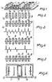
- figure 1 is a schematic perspective view of a practical representation of the identification code, in which the regions with greater magnetic intensity are indicated by a greater thickness and the different coercivity of the magnetic material which constitutes said regions is schematically indicated by sloping lines and dots;
- figure 2 is a schematic plan view of the code regions of fig. 1 pointing out the different coercivity thereof;
- figure 3 is a plan view, with orientation indication, of the code regions after a first orientation step, and the corresponding electrical signal as generated by the magnetic read head;
- figure 4 is a view of the code regions after a second different orientation step, and the corresponding electrical signal as generated by the magnetic head;
- figure 5 is a view of the orientation of all the code regions after code readout has been performed;
- figure 6 is a schematic view of the magnetic code sensing unit.
-
- With reference to the above figures, the identification code for documents and the like comprises a plurality of magnetic regions, generally indicated by the reference numeral 1, which are mutually spaced apart and are obtained by deposition for example of magnetic iron oxide.
- Said regions 1 in practice constitute a bar code, since the various magnetic regions are separated by
blank spaces 2. - Advantageously, the regions 1 have a different magnetic intensity which is obtained according to the characteristics illustrated in the above mentioned European patent application.
- The peculiarity of the code resides in that at least one part of said regions 1, indicated at 1a, has a magnetic coercivity which differs with respect to the remaining regions, indicated at 1b.
- As a specific example, the regions 1a may have a high magnetic coercivity, for example 4000 Oe, whereas the regions 1b may have a low magnetic coercivity, for example 350 Oe.
- This different coercivity is obtained by using different ranges of products, for example of the kind commercially known by the trade-name Bayferrox; it is also possible to obtain a plurality of groups of regions with different magnetic coercivity, further increasing the degree of security for magnetic sensing.
- With the above described specific example, it is possible to perform two different sensings of the same plurality of regions by varying the magnetic field which orientates the regions.
- Again with reference to the above described specific example, in which two different groups of regions with two different coercivities are provided, it is possible to perform a first readout by applying a first magnetic field for orientating all the regions 1; thus, for example, as illustrated in figure 3, it is possible to orientate the magnetic regions with a N-S, N-S, ..., N-S arrangement along the direction in which the code is read or sensed, which is advantageously perpendicular to the extension of said regions, i.e. in the direction in which the various regions are side-by-side.
- Then, by means of a magnetic sensing head, the code is read and an electrical signal is obtained, which has two pulses at each magnetic region, the intensity of these pulses corresponding to the magnetic intensity of said region.
- Once this first readout has been performed, a second magnetic field is applied having such an intensity as to modify the orientation exclusively of the regions which have a low coercivity or in any case such a coercivity as to be affected by the applied magnetic field. In this manner, as illustrated in figure 4, some regions (with higher coercivity) preserve the North-South orientation in the readout direction, while other regions, i.e. those with lower coercivity, have a North-South orientation which is perpendicular to the read direction; in these conditions, the electrical signal obtained in the subsequent sensing step, has pulses only at the regions with North-South orientation in the readout direction, providing a readout which is different from the one performed earlier though it is done on the same plurality of regions.
- In order to perform said readouts it is possible to use a magnetic sensing unit as illustrated in figure 6 and comprising an entry magnet, indicated at 10, which generates a magnetic field capable of orientating all the regions along the North-South direction in the readout direction; a first read head 11 is arranged to the side of the
entry magnet 10 and magnetically reads all the regions, generating an electrical signal which is a function of the position of such regions and of their intensity. After the first read head, the unit is provided with a de-orientation magnet, indicated at 15, which generates a magnetic field according to a different direction with respect to the direction generated by the entry magnet and along a perpendicular direction. The magnetic intensity of thede-orientation magnet 15 is such as to vary the magnetic orientation exclusively of the part of regions which has low coercivity, whereas the regions with high coercivity are in practice not influenced by the de-orientation magnet. - A second magnetic read head, indicated at 16, is provided next to the de-orientation magnet, downstream with respect to the readout direction of the document, and detects exclusively the regions which are not de-orientated, i.e. the regions which still have the North-South magnetic orientation in the read direction, while in practice it does not sense the regions in which the orientation has been varied and arranged perpendicular to the read direction.
- An exit magnet, indicated at 18, is arranged next to the second read head and has the function of re-orientating all the regions, i.e. both with low and high coercivity, so that the document is ready for a subsequent readout, and so that if it is examined with a magnetic lens it does not allow to point out regions with a different magnetic orientation.
- With this code, i.e. by virtue of the presence of magnetic regions with different coercivity, it is possible to read in practice a code within the code, i.e. to perform two different readouts, both of which can be decoded for authentic documents, thus constituting a further degree of anti-forgery security.
- From what has been described above it can thus be seen that the invention provides two different sensing levels and consequently two different readouts which can be individually detected and decoded, ensure authenticity in the most absolute manner.
- The invention thus conceived is susceptible to numerous modifications and variations, all of which are within the scope of the inventive concept. In particular, since the code regions may have more than two different coercivities, the sensing unit may present more than one de-orientation magnet.
- In practice, the materials employed, as well as the dimensions and contingent shapes, may be any according to the requirements.
- Where technical features mentioned in any claim are followed by reference signs, those reference signs have been included for the sole purpose of increasing the intelligibility of the claims and accordingly, such reference signs do not have any limiting effect on the scope of each element identified by way of example by such reference signs.
Claims (2)
- A method for sensing an identification code defined by a plurality of magnetic regions (1) arranged in a line and mutually separated by blank spaces i.e. non-magnetic (2) and including at least one first part (1a) of said regions having a magnetic coercivity which differs from that of the remaining second part of said regions (1b), the different coercivities of said first and second parts being such that upon application of at least two different magnetic fields to said regions, the regions of said first and second parts respectively, have different magnetic orientations, said regions thereby being able to generate at least two different electrical signal readouts from the same said plurality of regions, the method comprising the following sequential steps of:generating a magnetic field for orientating all of the plurality of magnetic regions (1) in the same first direction;reading the code by generating an electrical signal having pulses the position whereof is a function of the width of each of the magnetic regions (1) and the amplitude whereof is a function of the intensity of the magnetic field generated by each magnetic region (1);varying the orientation in a direction substantially perpendicular to said first direction selectively only of said one part of the magnetic regions which has the lower coercivity; andreading the code by generating an electrical signal having pulses the position whereof is a function of the width of only each of the magnetic regions of said other part which has the higher coercivity.
- A unit for sensing an identification code defined by a plurality of magnetic regions (1) arranged in a line and mutually separated by blank spaces i.e. non-magnetic areas (2) and including at least one first part (1a) of said plurality of regions having a magnetic coercivity which differs from that of the remaining second part (1b) of said regions, the different coercivities of said first and second parts being such that upon application of at least two different magnetic fields to said regions, the regions of said first and second parts respectively, have different magnetic orientations, said regions thereby being able to generate at least two different electrical signal readouts from the same said plurality of regions, the unit comprising: an entry magnet (10) which generates a magnetic field adapted to orientate all of the plurality of magnetic regions (1) defining the code in the same direction; a first magnetic read head (11) which is arranged downstream in the direction of travel of the code in the unit with respect to said entry magnet which generates an electrical signal having pulses the position whereof is a function of the width of the magnetic regions (1) and of the said blank spaces (2) interposed therebetween in the read direction, and the amplitude whereof is a function of the intensity of the magnetic field generated by each magnetic region (1); a de-orientation magnet (15) which is arranged downstream in the direction of travel of the code in the unit with respect to said first magnetic read head and which varies the orientation only of the one said part of said plurality of magnetic regions which has the lower coercivity, and said de-orientation magnet (15) generates a magnetic field in a direction which is substantially perpendicular to the field generated by said entry magnet (10); a second read head (16), which is arranged downstream in the direction of travel of the code in the unit with respect to said de-orientation magnet and which generates an electrical signal having pulses the position whereof is a function of the width of only the other said part of said plurality of magnetic regions which has the higher coercivity; and an exit magnet (18) which is arranged downstream in the direction of travel of the code in the unit with respect to said second read head and which generates a magnetic field adapted for re-orientating all of the regions of said plurality of magnetic regions in the same direction.
Priority Applications (7)
| Application Number | Priority Date | Filing Date | Title |
|---|---|---|---|
| DE68926714T DE68926714T3 (en) | 1989-11-23 | 1989-11-23 | Unit for scanning magnetic codes |
| EP89121610A EP0428779B2 (en) | 1989-11-23 | 1989-11-23 | Unit for sensing magnetic codes |
| ES89121610T ES2088884T5 (en) | 1989-11-23 | 1989-11-23 | UNIT TO DETECT MAGNETIC CODES. |
| AT89121610T ATE139636T1 (en) | 1989-11-23 | 1989-11-23 | CODE FOR IDENTIFYING DOCUMENTS AND THE LIKE AND UNIT FOR SENSING MAGNETIC CODES |
| US07/441,668 US5196681A (en) | 1989-11-23 | 1989-11-27 | Magnetic ink medium and corresponding reading unit, and method for using same |
| GR960401485T GR3020650T3 (en) | 1989-11-23 | 1996-07-31 | Identification code for documents and the like and unit for sensing magnetic codes |
| GR990403238T GR3032152T3 (en) | 1989-11-23 | 1999-12-15 | Identification code for documents and the like and unit for sensing magnetic codes. |
Applications Claiming Priority (1)
| Application Number | Priority Date | Filing Date | Title |
|---|---|---|---|
| EP89121610A EP0428779B2 (en) | 1989-11-23 | 1989-11-23 | Unit for sensing magnetic codes |
Publications (3)
| Publication Number | Publication Date |
|---|---|
| EP0428779A1 EP0428779A1 (en) | 1991-05-29 |
| EP0428779B1 EP0428779B1 (en) | 1996-06-19 |
| EP0428779B2 true EP0428779B2 (en) | 1999-10-06 |
Family
ID=8202152
Family Applications (1)
| Application Number | Title | Priority Date | Filing Date |
|---|---|---|---|
| EP89121610A Expired - Lifetime EP0428779B2 (en) | 1989-11-23 | 1989-11-23 | Unit for sensing magnetic codes |
Country Status (6)
| Country | Link |
|---|---|
| US (1) | US5196681A (en) |
| EP (1) | EP0428779B2 (en) |
| AT (1) | ATE139636T1 (en) |
| DE (1) | DE68926714T3 (en) |
| ES (1) | ES2088884T5 (en) |
| GR (2) | GR3020650T3 (en) |
Cited By (1)
| Publication number | Priority date | Publication date | Assignee | Title |
|---|---|---|---|---|
| CN108629885A (en) * | 2011-12-13 | 2018-10-09 | 捷德货币技术有限责任公司 | The method and apparatus for checking valuable document |
Families Citing this family (29)
| Publication number | Priority date | Publication date | Assignee | Title |
|---|---|---|---|---|
| GB2261847B (en) * | 1991-11-23 | 1995-09-27 | Pentagon Trading Ltd | Document with security devices for verifying the authenticity and completeness of the document by means of scanning equipment |
| US5418458A (en) * | 1993-08-31 | 1995-05-23 | Eastman Kodak Company | Apparatus and method for authentication of documents printed with magnetic ink |
| US5480685A (en) * | 1993-10-22 | 1996-01-02 | Tomoegawa Paper Co., Ltd. | Method of making a magnetic recording medium comprising two magnetic layers |
| US5643686A (en) * | 1994-01-06 | 1997-07-01 | Tokyo Magnetic Printing Co., Ltd. | Magnetic recording medium and method for manufacturing the same |
| GB2290897B (en) * | 1994-06-28 | 1998-07-01 | Lee Ming Cheng | Magnetic cards |
| US5697649A (en) * | 1995-05-11 | 1997-12-16 | Crane & Co., Inc. | Articles employing a magnetic security feature |
| US5614824A (en) * | 1995-05-15 | 1997-03-25 | Crane & Co., Inc. | Harmonic-based verifier device for a magnetic security thread having linear and non-linear ferromagnetic characteristics |
| US5616911A (en) * | 1995-05-24 | 1997-04-01 | Eastman Kodak Company | Read-only magnetic security pattern |
| JPH09167308A (en) * | 1995-12-19 | 1997-06-24 | Canon Electron Inc | Magnetic reproducing method, magnetic detecting element, magnetic detector and magnetic recording medium |
| US6053406A (en) * | 1996-05-17 | 2000-04-25 | Aveka, Inc. | Antiforgery security system |
| US5988500A (en) * | 1996-05-17 | 1999-11-23 | Aveka, Inc. | Antiforgery security system |
| GB2324644B (en) * | 1997-04-22 | 2001-09-12 | Central Research Lab Ltd | Apparatus for reading permanently structured magnetic records |
| US6930606B2 (en) * | 1997-12-02 | 2005-08-16 | Crane & Co., Inc. | Security device having multiple security detection features |
| UA52804C2 (en) | 1997-12-02 | 2003-01-15 | Текнікал Графікс Сек'Юріті Продактс, Ллс | Device for protecting documents by using magnetic and metallic protective elements (variants); method for producing the protection device (variants); method for identifying documents |
| DE29822967U1 (en) * | 1998-12-23 | 2000-05-11 | Espe Dental Ag | Device for spreading flowable masses |
| WO2001026060A2 (en) | 1999-10-07 | 2001-04-12 | Technical Graphics Security Products, Llc | Security device with foil camouflaged magnetic regions and methods of making same |
| DE10317810A1 (en) * | 2003-04-16 | 2004-11-04 | Giesecke & Devrient Gmbh | Security element and test method for a value document |
| US7243951B2 (en) * | 2003-08-19 | 2007-07-17 | Technical Graphics, Inc. | Durable security devices and security articles employing such devices |
| JP4525242B2 (en) * | 2004-08-23 | 2010-08-18 | 富士ゼロックス株式会社 | Medium provided with magnetic substance and magnetic substance detection device |
| DE102004049999A1 (en) * | 2004-10-14 | 2006-04-20 | Giesecke & Devrient Gmbh | security element |
| ITMI20080053A1 (en) | 2008-01-15 | 2009-07-16 | Fabriano Securities Srl | SECURITY ELEMENT, PARTICULARLY FOR BANKNOTES, SECURITY CARDS AND THE LIKE, WITH AN ANTI-COUNTERFEIT CHARACTERISTICS. |
| ITMI20080261A1 (en) | 2008-02-19 | 2009-08-20 | Fabriano Securities Srl | BANKNOTES READING SENSOR, SECURITY CARDS AND THE LIKE, CONTAINING AT LEAST A SECURITY ELEMENT. |
| UA100203C2 (en) | 2009-04-01 | 2012-11-26 | Федригони С.П.А. | Security element comprising magnetic areas of different coercivity, security card, method of manufacturing security element and method of readinginformation coded in security element |
| DE102009039588A1 (en) | 2009-09-01 | 2011-03-03 | Giesecke & Devrient Gmbh | Method and device for checking value documents |
| US8910869B2 (en) | 2010-06-09 | 2014-12-16 | Giesecke & Devrient Gmbh | Method and apparatus for checking value documents |
| US9000759B2 (en) * | 2010-12-22 | 2015-04-07 | Ncr Corporation | Magnetic sensor |
| WO2022096241A1 (en) | 2020-11-05 | 2022-05-12 | Mantegazza Patrizia Giuseppina | Magnetic security element and its method of fabrication |
| CN113011209B (en) * | 2021-04-08 | 2022-07-08 | 浙江新凯迪数字科技股份有限公司 | Physical industry Internet system and transfer box information acquisition method |
| WO2023274728A1 (en) | 2021-06-29 | 2023-01-05 | Eptainks S.P.A. | High-security magnetic security element for valued papers |
Family Cites Families (7)
| Publication number | Priority date | Publication date | Assignee | Title |
|---|---|---|---|---|
| US3790754A (en) * | 1972-08-04 | 1974-02-05 | Burroughs Machines Ltd | Security access medium |
| US4114029A (en) * | 1974-10-16 | 1978-09-12 | E M I Limited | Magnetic recording |
| GB1534859A (en) * | 1976-06-04 | 1978-12-06 | De La Rue Crosfield | Detector for documents comprising magnetizable material |
| FR2435778A1 (en) * | 1978-08-01 | 1980-04-04 | Pyral Soc | SECURITY MAGNETIC RECORDING MEDIUM |
| DE2950174A1 (en) * | 1979-12-13 | 1981-06-19 | Basf Ag, 6700 Ludwigshafen | METHOD AND DEVICE FOR CHECKING THE AUTHENTICITY OF RECORDING CARRIERS TO BE SECURED AGAINST COUNTERFEITING |
| US4734643A (en) * | 1985-08-05 | 1988-03-29 | Electrocom Automation, Inc. | Method and apparatus for detecting the presence of magnetic ink within a package by magnetizing and selectively remagnitizing the ferro-magnetic materials in the package |
| IT1222851B (en) * | 1987-10-08 | 1990-09-12 | Mantegazza A Arti Grafici | MAGNETICALLY DETECTABLE IDENTIFICATION CODE TO MARK PRODUCTS, DOCUMENTS AND SIMILAR |
-
1989
- 1989-11-23 DE DE68926714T patent/DE68926714T3/en not_active Expired - Lifetime
- 1989-11-23 EP EP89121610A patent/EP0428779B2/en not_active Expired - Lifetime
- 1989-11-23 ES ES89121610T patent/ES2088884T5/en not_active Expired - Lifetime
- 1989-11-23 AT AT89121610T patent/ATE139636T1/en not_active IP Right Cessation
- 1989-11-27 US US07/441,668 patent/US5196681A/en not_active Expired - Lifetime
-
1996
- 1996-07-31 GR GR960401485T patent/GR3020650T3/en unknown
-
1999
- 1999-12-15 GR GR990403238T patent/GR3032152T3/en unknown
Cited By (1)
| Publication number | Priority date | Publication date | Assignee | Title |
|---|---|---|---|---|
| CN108629885A (en) * | 2011-12-13 | 2018-10-09 | 捷德货币技术有限责任公司 | The method and apparatus for checking valuable document |
Also Published As
| Publication number | Publication date |
|---|---|
| EP0428779A1 (en) | 1991-05-29 |
| US5196681A (en) | 1993-03-23 |
| GR3032152T3 (en) | 2000-04-27 |
| DE68926714D1 (en) | 1996-07-25 |
| EP0428779B1 (en) | 1996-06-19 |
| DE68926714T3 (en) | 2000-01-05 |
| DE68926714T2 (en) | 1996-10-31 |
| GR3020650T3 (en) | 1996-10-31 |
| ES2088884T5 (en) | 1999-11-16 |
| ES2088884T3 (en) | 1996-10-01 |
| ATE139636T1 (en) | 1996-07-15 |
Similar Documents
| Publication | Publication Date | Title |
|---|---|---|
| EP0428779B2 (en) | Unit for sensing magnetic codes | |
| EP0632398B1 (en) | Method and apparatus for checking whether or not objects are authentic | |
| EP0625766B1 (en) | Authenticity checking of objects | |
| US4507550A (en) | High security credit card, system and method | |
| US5601931A (en) | Object to be checked for authenticity and a method for manufacturing the same | |
| US3566356A (en) | Magnetic recording document and method | |
| US5583333A (en) | Checking objects including bistable magnetic devices, to be checked for authenticity | |
| US5616911A (en) | Read-only magnetic security pattern | |
| US4982076A (en) | Magnetic recording medium | |
| EP0589195B1 (en) | A method and an apparatus for checking objects to be checked for authenticity | |
| US4197989A (en) | Magnetic recording | |
| JPH06103423A (en) | Method for preventing illicit usage of magnetic card and the like and magnetic card | |
| EP0094775B1 (en) | A method of preparing and reading information which is permananently recorded on a magnetic layer | |
| JP2821367B2 (en) | Card-like object to be checked for authenticity and method of manufacturing the same | |
| JP2718624B2 (en) | Detected object whose authenticity is checked and method of manufacturing the same | |
| JP2687344B2 (en) | Magnetic medium and its confirmation method | |
| EP0815541A1 (en) | Security system for documents with a magnetic track for recording information | |
| JP2680980B2 (en) | Method and apparatus for checking authenticity of an object to be detected | |
| JPS63133321A (en) | Magnetic recording medium | |
| JPH09277767A (en) | Product to be sensed for checking its genuinness and checking method for product to be sensed | |
| JPH0732777A (en) | Matter to be checked for genuineness and method and apparatus for checking genuineness of the same | |
| JP3051133B2 (en) | Identification code and magnetic code detector for documents etc. | |
| JPH06274848A (en) | Information recording medium | |
| JP3501537B2 (en) | An object whose authenticity is to be checked and a method of checking the authenticity of this object | |
| JP2554078B2 (en) | Magnetic recording medium and reproducing method thereof |
Legal Events
| Date | Code | Title | Description |
|---|---|---|---|
| PUAI | Public reference made under article 153(3) epc to a published international application that has entered the european phase |
Free format text: ORIGINAL CODE: 0009012 |
|
| 17P | Request for examination filed |
Effective date: 19901109 |
|
| AK | Designated contracting states |
Kind code of ref document: A1 Designated state(s): AT BE CH DE ES FR GB GR LI LU NL SE |
|
| 17Q | First examination report despatched |
Effective date: 19940114 |
|
| GRAH | Despatch of communication of intention to grant a patent |
Free format text: ORIGINAL CODE: EPIDOS IGRA |
|
| GRAH | Despatch of communication of intention to grant a patent |
Free format text: ORIGINAL CODE: EPIDOS IGRA |
|
| GRAA | (expected) grant |
Free format text: ORIGINAL CODE: 0009210 |
|
| AK | Designated contracting states |
Kind code of ref document: B1 Designated state(s): AT BE CH DE ES FR GB GR LI LU NL SE |
|
| REF | Corresponds to: |
Ref document number: 139636 Country of ref document: AT Date of ref document: 19960715 Kind code of ref document: T |
|
| REG | Reference to a national code |
Ref country code: CH Ref legal event code: NV Representative=s name: PATENTANWALTSBUERO JEAN HUNZIKER |
|
| REF | Corresponds to: |
Ref document number: 68926714 Country of ref document: DE Date of ref document: 19960725 |
|
| ET | Fr: translation filed | ||
| REG | Reference to a national code |
Ref country code: GR Ref legal event code: FG4A Free format text: 3020650 |
|
| REG | Reference to a national code |
Ref country code: ES Ref legal event code: FG2A Ref document number: 2088884 Country of ref document: ES Kind code of ref document: T3 |
|
| REG | Reference to a national code |
Ref country code: ES Ref legal event code: FG2A Ref document number: 2088884 Country of ref document: ES Kind code of ref document: T3 |
|
| PLBI | Opposition filed |
Free format text: ORIGINAL CODE: 0009260 |
|
| PLBF | Reply of patent proprietor to notice(s) of opposition |
Free format text: ORIGINAL CODE: EPIDOS OBSO |
|
| 26 | Opposition filed |
Opponent name: GIESECKE & DEVRIENT GMBH Effective date: 19970319 |
|
| NLR1 | Nl: opposition has been filed with the epo |
Opponent name: GIESECKE & DEVRIENT GMBH |
|
| PLBF | Reply of patent proprietor to notice(s) of opposition |
Free format text: ORIGINAL CODE: EPIDOS OBSO |
|
| PLBF | Reply of patent proprietor to notice(s) of opposition |
Free format text: ORIGINAL CODE: EPIDOS OBSO |
|
| PLAW | Interlocutory decision in opposition |
Free format text: ORIGINAL CODE: EPIDOS IDOP |
|
| PLAW | Interlocutory decision in opposition |
Free format text: ORIGINAL CODE: EPIDOS IDOP |
|
| RTI2 | Title (correction) |
Free format text: UNIT FOR SENSING MAGNETIC CODES |
|
| PUAH | Patent maintained in amended form |
Free format text: ORIGINAL CODE: 0009272 |
|
| STAA | Information on the status of an ep patent application or granted ep patent |
Free format text: STATUS: PATENT MAINTAINED AS AMENDED |
|
| 27A | Patent maintained in amended form |
Effective date: 19991006 |
|
| AK | Designated contracting states |
Kind code of ref document: B2 Designated state(s): AT BE CH DE ES FR GB GR LI LU NL SE |
|
| REG | Reference to a national code |
Ref country code: CH Ref legal event code: AEN Free format text: AUFRECHTERHALTUNG DES PATENTES IN GEAENDERTER FORM |
|
| REG | Reference to a national code |
Ref country code: ES Ref legal event code: DC2A Kind code of ref document: T5 Effective date: 19991013 |
|
| NLR2 | Nl: decision of opposition | ||
| ET3 | Fr: translation filed ** decision concerning opposition | ||
| NLR3 | Nl: receipt of modified translations in the netherlands language after an opposition procedure | ||
| REG | Reference to a national code |
Ref country code: GB Ref legal event code: IF02 |
|
| REG | Reference to a national code |
Ref country code: CH Ref legal event code: PUE Owner name: FABRIANO SECURITIES S.R.L. Free format text: MANTEGAZZA ANTONIO ARTI GRAFICHE S.R.L.#VIA MILANO 71#20021 OSPIATE DI BOLLATE (MILAN) (IT) -TRANSFER TO- FABRIANO SECURITIES S.R.L.#VIA DEL LINFANO, 16#38062 ARCO (TRENTO) (IT) |
|
| REG | Reference to a national code |
Ref country code: GB Ref legal event code: 732E |
|
| NLS | Nl: assignments of ep-patents |
Owner name: FABRIANO SECURITIES S.R.L. Effective date: 20050621 |
|
| REG | Reference to a national code |
Ref country code: FR Ref legal event code: TP |
|
| PGFP | Annual fee paid to national office [announced via postgrant information from national office to epo] |
Ref country code: DE Payment date: 20081127 Year of fee payment: 20 Ref country code: NL Payment date: 20081128 Year of fee payment: 20 Ref country code: CH Payment date: 20081022 Year of fee payment: 20 Ref country code: LU Payment date: 20081016 Year of fee payment: 20 |
|
| PGFP | Annual fee paid to national office [announced via postgrant information from national office to epo] |
Ref country code: ES Payment date: 20080929 Year of fee payment: 20 Ref country code: AT Payment date: 20081110 Year of fee payment: 20 |
|
| PGFP | Annual fee paid to national office [announced via postgrant information from national office to epo] |
Ref country code: BE Payment date: 20081003 Year of fee payment: 20 Ref country code: SE Payment date: 20081112 Year of fee payment: 20 |
|
| PGFP | Annual fee paid to national office [announced via postgrant information from national office to epo] |
Ref country code: FR Payment date: 20080929 Year of fee payment: 20 |
|
| PGFP | Annual fee paid to national office [announced via postgrant information from national office to epo] |
Ref country code: GR Payment date: 20080930 Year of fee payment: 20 Ref country code: GB Payment date: 20081020 Year of fee payment: 20 |
|
| BE20 | Be: patent expired |
Owner name: *FABRIANO SECURITIES S.R.L. Effective date: 20091123 |
|
| REG | Reference to a national code |
Ref country code: CH Ref legal event code: PL |
|
| REG | Reference to a national code |
Ref country code: GB Ref legal event code: PE20 Expiry date: 20091122 |
|
| REG | Reference to a national code |
Ref country code: ES Ref legal event code: FD2A Effective date: 20091124 |
|
| NLV7 | Nl: ceased due to reaching the maximum lifetime of a patent |
Effective date: 20091123 |
|
| PG25 | Lapsed in a contracting state [announced via postgrant information from national office to epo] |
Ref country code: NL Free format text: LAPSE BECAUSE OF EXPIRATION OF PROTECTION Effective date: 20091123 |
|
| PG25 | Lapsed in a contracting state [announced via postgrant information from national office to epo] |
Ref country code: ES Free format text: LAPSE BECAUSE OF EXPIRATION OF PROTECTION Effective date: 20091124 Ref country code: GB Free format text: LAPSE BECAUSE OF EXPIRATION OF PROTECTION Effective date: 20091122 |