EP0428134A2 - Fault diagnosing apparatus and method - Google Patents
Fault diagnosing apparatus and method Download PDFInfo
- Publication number
- EP0428134A2 EP0428134A2 EP90121714A EP90121714A EP0428134A2 EP 0428134 A2 EP0428134 A2 EP 0428134A2 EP 90121714 A EP90121714 A EP 90121714A EP 90121714 A EP90121714 A EP 90121714A EP 0428134 A2 EP0428134 A2 EP 0428134A2
- Authority
- EP
- European Patent Office
- Prior art keywords
- fault
- choices
- question
- repair items
- respect
- Prior art date
- Legal status (The legal status is an assumption and is not a legal conclusion. Google has not performed a legal analysis and makes no representation as to the accuracy of the status listed.)
- Withdrawn
Links
Images


Classifications
-
- G—PHYSICS
- G06—COMPUTING; CALCULATING OR COUNTING
- G06F—ELECTRIC DIGITAL DATA PROCESSING
- G06F11/00—Error detection; Error correction; Monitoring
- G06F11/22—Detection or location of defective computer hardware by testing during standby operation or during idle time, e.g. start-up testing
- G06F11/2257—Detection or location of defective computer hardware by testing during standby operation or during idle time, e.g. start-up testing using expert systems
-
- G—PHYSICS
- G05—CONTROLLING; REGULATING
- G05B—CONTROL OR REGULATING SYSTEMS IN GENERAL; FUNCTIONAL ELEMENTS OF SUCH SYSTEMS; MONITORING OR TESTING ARRANGEMENTS FOR SUCH SYSTEMS OR ELEMENTS
- G05B19/00—Programme-control systems
- G05B19/02—Programme-control systems electric
- G05B19/04—Programme control other than numerical control, i.e. in sequence controllers or logic controllers
- G05B19/042—Programme control other than numerical control, i.e. in sequence controllers or logic controllers using digital processors
- G05B19/0428—Safety, monitoring
-
- G—PHYSICS
- G05—CONTROLLING; REGULATING
- G05B—CONTROL OR REGULATING SYSTEMS IN GENERAL; FUNCTIONAL ELEMENTS OF SUCH SYSTEMS; MONITORING OR TESTING ARRANGEMENTS FOR SUCH SYSTEMS OR ELEMENTS
- G05B2219/00—Program-control systems
- G05B2219/20—Pc systems
- G05B2219/23—Pc programming
- G05B2219/23157—Display process, synoptic, legend, pictogram, mimic
-
- G—PHYSICS
- G05—CONTROLLING; REGULATING
- G05B—CONTROL OR REGULATING SYSTEMS IN GENERAL; FUNCTIONAL ELEMENTS OF SUCH SYSTEMS; MONITORING OR TESTING ARRANGEMENTS FOR SUCH SYSTEMS OR ELEMENTS
- G05B2219/00—Program-control systems
- G05B2219/20—Pc systems
- G05B2219/24—Pc safety
- G05B2219/24018—Computer assisted repair, diagnostic
-
- G—PHYSICS
- G05—CONTROLLING; REGULATING
- G05B—CONTROL OR REGULATING SYSTEMS IN GENERAL; FUNCTIONAL ELEMENTS OF SUCH SYSTEMS; MONITORING OR TESTING ARRANGEMENTS FOR SUCH SYSTEMS OR ELEMENTS
- G05B2219/00—Program-control systems
- G05B2219/20—Pc systems
- G05B2219/24—Pc safety
- G05B2219/24053—Diagnostic of controlled machine
-
- G—PHYSICS
- G05—CONTROLLING; REGULATING
- G05B—CONTROL OR REGULATING SYSTEMS IN GENERAL; FUNCTIONAL ELEMENTS OF SUCH SYSTEMS; MONITORING OR TESTING ARRANGEMENTS FOR SUCH SYSTEMS OR ELEMENTS
- G05B2219/00—Program-control systems
- G05B2219/20—Pc systems
- G05B2219/24—Pc safety
- G05B2219/24085—Analyze, trace fault signals according to tree, table
-
- G—PHYSICS
- G05—CONTROLLING; REGULATING
- G05B—CONTROL OR REGULATING SYSTEMS IN GENERAL; FUNCTIONAL ELEMENTS OF SUCH SYSTEMS; MONITORING OR TESTING ARRANGEMENTS FOR SUCH SYSTEMS OR ELEMENTS
- G05B2219/00—Program-control systems
- G05B2219/20—Pc systems
- G05B2219/24—Pc safety
- G05B2219/24086—Expert system, guidance operator, locate fault and indicate how to repair
-
- G—PHYSICS
- G05—CONTROLLING; REGULATING
- G05B—CONTROL OR REGULATING SYSTEMS IN GENERAL; FUNCTIONAL ELEMENTS OF SUCH SYSTEMS; MONITORING OR TESTING ARRANGEMENTS FOR SUCH SYSTEMS OR ELEMENTS
- G05B2219/00—Program-control systems
- G05B2219/20—Pc systems
- G05B2219/24—Pc safety
- G05B2219/24087—After correct repair, update fault tree
-
- G—PHYSICS
- G05—CONTROLLING; REGULATING
- G05B—CONTROL OR REGULATING SYSTEMS IN GENERAL; FUNCTIONAL ELEMENTS OF SUCH SYSTEMS; MONITORING OR TESTING ARRANGEMENTS FOR SUCH SYSTEMS OR ELEMENTS
- G05B2219/00—Program-control systems
- G05B2219/20—Pc systems
- G05B2219/24—Pc safety
- G05B2219/24093—Display, show place of error, fault
Definitions
- the present invention relates to a fault diagnosing apparatus for detecting the cause of a fault when a control target in, e.g., a sequence control system failed, and to a corresponding diagnosing method.
- a control target such as a plant, a processing apparatus, or an equipment system
- a control target is properly operated by controlling a large number of sensors and actuators, e.g., limit switches and solenoid valves, at predetermined timings based on a sequence program using a sequence controller in accordance with signals from various sensors arranged at the respective portions of the control target.
- sensors and actuators e.g., limit switches and solenoid valves
- a system has a function of diagnosing a fault in a control target during an operation. When a fault is detected, the fault is displayed by means of a lamp, a message, or the like.
- faults are very roughly diagnosed, and the number of items of faults which can be detected is very small.
- the number of items is about 10 to 250.
- fault diagnosis of the above-mentioned sequence controller itself including a large number of contacts and actuators, various sensors, and the like, is performed.
- the display contents of abnormal states are limited to only phenomena, and true causes thereof are not displayed at all.
- sequence program includes a control program and a program for fault diagnosis.
- the two programs are alternately executed. Therefore, the total capacity of programs is increased to increase a programming load. This may also interfere with the execution of the control program, and pose other problems, e.g., that fault diagnosis cannot be performed at high speed.
- an operator in charge of maintenance checks a portion at which the fault has occurred, and also checks an operation manual. The operator then determines the cause of the fault or the repair items and performs a proper operation.
- MTTR total time to repair faults/total number of faults to be repaired
- the present invention has been made to solve the above problem, and has as its object to provide a fault diagnosing apparatus which can detect the cause of a fault within a short period of time and can inform an operator of repair items indicating a repair method.
- a fault diagnosing apparatus comprising a fault tree in which a plurality of choices are set with respect to one question associated with a cause of a fault of a fault diagnosis target, answers and choices branch off from each of the choices, and final choices reach causes of the fault, storage means for storing fault repair items with respect to the causes of the fault, read control means for, in response to an input operation to select one of the choices, reading out the selected choice, a corresponding question, choices branching off therefrom, and fault repair items, and display means for displaying the question, the choices, and the fault repair items which are read out by the read control means.
- one or more repair items indicating a repair method of the fault can be displayed.
- reference numeral 1 denotes a sequence controller; 2, a large press machine as a control target to be controlled by the sequence controller 1; 1a, a fault detecting section, of the sequence controller 1, for detecting an abnormal state (fault) of the press machine 2; 1b, a control section, of the sequence controller 1, for controlling an operation of the press machine 2 and roughly detecting a fault; 3, a fault diagnosis apparatus, constituted by a memory 3a, a CPU, and the like, for checking the cause of a fault on the basis of a fault detection signal from the sequence controller 1; 4, a display section, constituted by a CRT or the like and connected to the fault diagnosing apparatus 3, for displaying questions, answers, probabilities, and the like in accordance with the interaction between an operator and the apparatus 3; and 5, a keyboard for inputting an answer selected by the operator with respect to the apparatus 3.
- a fault diagnosis apparatus constituted by a memory 3a, a CPU, and the like, for checking the cause of a fault on the basis of a fault detection signal from
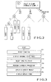
- Fig. 2 shows various data including a fault tree and the like registered in the memory 3a.
- a first question Q1 is set in relation to one fault.
- Three answers A1, A2, and A3 are prepared as choices with respect to the question Q1.
- Questions Q2, Q3, and Q4 are respectively set after the choices. These questions then branch out into choices.
- Final choices reach a cause 1, a cause 2, cause 3,....
- the memory 3a serves to store data representing the number of times the states of the answers A1, A2, and A3 as the choices constituting the fault tree occur, and data representing the number of times the respective answers are used (selected) in the past.
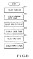
- step ST1 When a fault occurs in the press machine 2, the operator operates the keyboard 5 in step ST1 to select an abnormal state monitor function of the fault diagnosing apparatus. With this operation, a schematic representation of the press machine 2 shown in Fig. 4 is displayed on the display section 4. In this case, the display section 4 displays the occurrence of an abnormal state in a die clamper by changing the display color of hatched portions in Fig. 4.
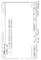
- step ST2 an abnormal state table shown in Fig. 5 is displayed.
- step ST4 When a specific point is designated from this table in step ST3, the flow advances to step ST4 to perform diagnosis processing in which selection of questions and answers is performed in an interactive mode in accordance with the above-mentioned fault tree. With this operation, a diagnosis result, i.e., the cause of the fault can be detected in step ST5.
- step ST5 a message shown in Fig. 7 is displayed, and a manual key is designated as one of function keys.
- An operator in charge of repair can perform a repair operation by referring to the above-mentioned repair items.
- Fig. 10 is a flow chart showing the diagnosis processing in step ST4 in more detail.
- step ST41 it is determined in step ST41 whether diagnosis processing is performed with respect to a specific abnormal state. If the keyboard 5 is operated to perform this processing, the display section 4 displays the first question Q1 (shown in Fig. 2) with respect to the designated point and the probabilities (frequencies) that the states of the answers (choices) A1, A2, and A3 for the question Q1 occur. These probabilities can be arbitrarily set and changed and can be displayed in an arbitrary order instead of displaying them in the order of decreasing values as in Fig. 6.
- step ST43 If the operator selects the answer A1 in step ST43, stack processing is performed in step ST44 to store the selected question Q1 and answer A1. Thereafter, it is checked in step ST45 whether the answer A1 is a final answer. If NO in step ST45, the flow returns to step ST42 to display the next question Q2 and its answers and waits for selection of an answer in step ST43. The above operation is repeated until the flow reaches to a final answer, and a selected question and answer are stored for each operation.
- a learning key is displayed on the display section 4 as one of function keys in step ST46. If this learning key is depressed once in step ST47, the counts of all the selected answers are updated in the memory 3a in step ST49 through step ST48. Note that if the learning key is consecutively depressed twice, the flow advances to step ST51 to perform error processing. Subsequently, in step ST50, the probabilities of the associated answers are calculated by using the counts updated in step ST49, and the memory 3a is updated on the basis of the calculation result.
- a learning function is added to the fault diagnosis function. That is, the accuracy of probabilities respectively displayed with respect to a plurality of answers for one question is increased every time diagnosis is performed to facilitate selection by an operator. Therefore, the cause of a fault can be detected within a short period of time.
- Fig. 11 is a flow chart showing another method of detecting the cause of a fault and fault repair items. Processing in steps ST1 to ST3 is executed in the same manner as described with reference to Fig. 3.
- a specific point is selected in step ST3
- a plurality of causes associated with the point are displayed together with their probabilities.
- Fig. 2 shows a case wherein the causes 1, 2, 3, ... associated with the question Q1 with respect to the specific point are displayed in the order of decreasing probabilities, as shown in Fig. 9.
- the fault repair items shown in Fig. 8 are displayed in step ST6.
- the present invention when selection of questions and answers is performed in the interactive mode by using a fault tree, one cause of a fault is obtained, and fault repair items are displayed.
- the cause of a fault can be detected within a short period of time.
- repair items for the fault can be detected. Therefore, the above-mentioned MTTR can be increased.
Landscapes
- Engineering & Computer Science (AREA)
- General Physics & Mathematics (AREA)
- Theoretical Computer Science (AREA)
- General Engineering & Computer Science (AREA)
- Physics & Mathematics (AREA)
- Quality & Reliability (AREA)
- Computer Hardware Design (AREA)
- Automation & Control Theory (AREA)
- Testing And Monitoring For Control Systems (AREA)
- Programmable Controllers (AREA)
- Testing Or Calibration Of Command Recording Devices (AREA)
- Testing Of Devices, Machine Parts, Or Other Structures Thereof (AREA)
- Test And Diagnosis Of Digital Computers (AREA)
Abstract
A fault diagnosing apparatus includes a fault tree, a storage section (3a), a read control section (3), a display section (4), a designating section (3), and a rewrite section (3). The fault tree is designed such that a plurality of choices are set with respect to one question associated with a cause of a fault of a fault diagnosing target, answers and choices branch off from each of the choices, and final choices reach causes of the fault. The storage section (3a) stores fault repair items with respect to the causes of the fault. In response to an input operation to select one of the choices, the read control section (3) reads out the selected choice, a corresponding question, choices branching off therefrom, and fault repair items. The display section (4) displays the question, the choices, and the fault repair items which are read out by the read control section.
Description
- The present invention relates to a fault diagnosing apparatus for detecting the cause of a fault when a control target in, e.g., a sequence control system failed, and to a corresponding diagnosing method.
- In a sequence control system, a control target, such as a plant, a processing apparatus, or an equipment system, is properly operated by controlling a large number of sensors and actuators, e.g., limit switches and solenoid valves, at predetermined timings based on a sequence program using a sequence controller in accordance with signals from various sensors arranged at the respective portions of the control target. In addition, such a system has a function of diagnosing a fault in a control target during an operation. When a fault is detected, the fault is displayed by means of a lamp, a message, or the like.
- In the conventional fault diagnosis, therefore, faults are very roughly diagnosed, and the number of items of faults which can be detected is very small. For example, in a press machine or the like, the number of items is about 10 to 250. In addition to fault diagnosis of a control target, fault diagnosis of the above-mentioned sequence controller itself, including a large number of contacts and actuators, various sensors, and the like, is performed. However, in the above-described fault diagnosis function, the display contents of abnormal states are limited to only phenomena, and true causes thereof are not displayed at all.
- Furthermore, the sequence program includes a control program and a program for fault diagnosis. The two programs are alternately executed. Therefore, the total capacity of programs is increased to increase a programming load. This may also interfere with the execution of the control program, and pose other problems, e.g., that fault diagnosis cannot be performed at high speed.
- In the above-described fault diagnosis function, when a fault is detected, an operation of a control target is stopped as needed and only a message of an abnormal state is displayed. However, more detailed fault diagnosis, e.g., information of the cause of the fault or repair items indicating a repair method of the fault, cannot be informed to a user.
- For this reason, when a fault is detected and displayed, an operator in charge of maintenance checks a portion at which the fault has occurred, and also checks an operation manual. The operator then determines the cause of the fault or the repair items and performs a proper operation.
- For this purpose, therefore, the operator is required to have experience and skill. In addition, it is generally difficult to properly read a large volume of an operation manual within a short period of time. For this reason, a fault repair may require a long period of time.
- Especially when a control target is a manufacturing machine such as a press machine, MTTR (mean time to repair = total time to repair faults/total number of faults to be repaired) is considered as an important factor. That is, it is important to repair a fault within a short period of time. For this purpose, it is very important to detect the cause of a fault within a short period of time.
- The present invention has been made to solve the above problem, and has as its object to provide a fault diagnosing apparatus which can detect the cause of a fault within a short period of time and can inform an operator of repair items indicating a repair method.
- In order to achieve the above object, according to the present invention, there is provided a fault diagnosing apparatus comprising a fault tree in which a plurality of choices are set with respect to one question associated with a cause of a fault of a fault diagnosis target, answers and choices branch off from each of the choices, and final choices reach causes of the fault, storage means for storing fault repair items with respect to the causes of the fault, read control means for, in response to an input operation to select one of the choices, reading out the selected choice, a corresponding question, choices branching off therefrom, and fault repair items, and display means for displaying the question, the choices, and the fault repair items which are read out by the read control means.
- After one cause of a fault is reached through a fault tree in an interactive mode, one or more repair items indicating a repair method of the fault can be displayed.
-
- Fig. 1 is a block diagram showing a sequence control system using a fault diagnosing apparatus according to the present invention;
- Fig. 2 is a view showing an arrangement of data, such as a fault tree, stored in a memory of the apparatus in Fig. 1;
- Fig. 3 is a flow chart showing an operation method to be executed by the apparatus in Fig. 1;
- Figs. 4 to 9 are views each showing a display screen of a display section used by the apparatus in Fig. 1;
- Fig. 10 is a flow chart showing diagnosis processing of the apparatus in Fig. 1; and
- Fig. 11 is a flow chart showing another operation method to be executed by the apparatus in Fig. 1.
- An embodiment of the present invention will be described below with reference to the accompanying drawings.
- Referring to Fig. 1,
reference numeral 1 denotes a sequence controller; 2, a large press machine as a control target to be controlled by thesequence controller 1; 1a, a fault detecting section, of thesequence controller 1, for detecting an abnormal state (fault) of thepress machine 2; 1b, a control section, of thesequence controller 1, for controlling an operation of thepress machine 2 and roughly detecting a fault; 3, a fault diagnosis apparatus, constituted by amemory 3a, a CPU, and the like, for checking the cause of a fault on the basis of a fault detection signal from thesequence controller 1; 4, a display section, constituted by a CRT or the like and connected to thefault diagnosing apparatus 3, for displaying questions, answers, probabilities, and the like in accordance with the interaction between an operator and theapparatus 3; and 5, a keyboard for inputting an answer selected by the operator with respect to theapparatus 3. - Fig. 2 shows various data including a fault tree and the like registered in the
memory 3a. - In this fault tree, a first question Q₁ is set in relation to one fault. Three answers A₁, A₂, and A₃ are prepared as choices with respect to the question Q₁. Questions Q₂, Q₃, and Q₄ are respectively set after the choices. These questions then branch out into choices. Final choices reach a
cause 1, acause 2,cause 3,.... Thememory 3a serves to store data representing the number of times the states of the answers A₁, A₂, and A₃ as the choices constituting the fault tree occur, and data representing the number of times the respective answers are used (selected) in the past. - An operation will be described below with reference to a flow chart in Fig. 3.
- When a fault occurs in the
press machine 2, the operator operates thekeyboard 5 in step ST1 to select an abnormal state monitor function of the fault diagnosing apparatus. With this operation, a schematic representation of thepress machine 2 shown in Fig. 4 is displayed on thedisplay section 4. In this case, thedisplay section 4 displays the occurrence of an abnormal state in a die clamper by changing the display color of hatched portions in Fig. 4. When thekeyboard 5 is operated again in step ST2, an abnormal state table shown in Fig. 5 is displayed. When a specific point is designated from this table in step ST3, the flow advances to step ST4 to perform diagnosis processing in which selection of questions and answers is performed in an interactive mode in accordance with the above-mentioned fault tree. With this operation, a diagnosis result, i.e., the cause of the fault can be detected in step ST5. In step ST5, a message shown in Fig. 7 is displayed, and a manual key is designated as one of function keys. - When the manual key designated by the
keyboard 5 is depressed, repair items with respect to the cause of a fault are displayed, as shown in Fig. 8. - An operator in charge of repair can perform a repair operation by referring to the above-mentioned repair items.
- Fig. 10 is a flow chart showing the diagnosis processing in step ST4 in more detail.
- Referring to Fig. 10, it is determined in step ST41 whether diagnosis processing is performed with respect to a specific abnormal state. If the
keyboard 5 is operated to perform this processing, thedisplay section 4 displays the first question Q₁ (shown in Fig. 2) with respect to the designated point and the probabilities (frequencies) that the states of the answers (choices) A₁, A₂, and A₃ for the question Q₁ occur. These probabilities can be arbitrarily set and changed and can be displayed in an arbitrary order instead of displaying them in the order of decreasing values as in Fig. 6. - If the operator selects the answer A₁ in step ST43, stack processing is performed in step ST44 to store the selected question Q₁ and answer A₁. Thereafter, it is checked in step ST45 whether the answer A₁ is a final answer. If NO in step ST45, the flow returns to step ST42 to display the next question Q₂ and its answers and waits for selection of an answer in step ST43. The above operation is repeated until the flow reaches to a final answer, and a selected question and answer are stored for each operation.
- The above-described operation is repeated in accordance with the fault tree until a final answer is obtained. If an answer for a question is erroneously selected, the flow can return to the step for the previous question.
- If a final answer, i.e., the cause of the fault, is selected and displayed, a learning key is displayed on the
display section 4 as one of function keys in step ST46. If this learning key is depressed once in step ST47, the counts of all the selected answers are updated in thememory 3a in step ST49 through step ST48. Note that if the learning key is consecutively depressed twice, the flow advances to step ST51 to perform error processing. Subsequently, in step ST50, the probabilities of the associated answers are calculated by using the counts updated in step ST49, and thememory 3a is updated on the basis of the calculation result. - As described above, by sequentially updating the above-mentioned probabilities, a learning function is added to the fault diagnosis function. That is, the accuracy of probabilities respectively displayed with respect to a plurality of answers for one question is increased every time diagnosis is performed to facilitate selection by an operator. Therefore, the cause of a fault can be detected within a short period of time.
- Fig. 11 is a flow chart showing another method of detecting the cause of a fault and fault repair items. Processing in steps ST1 to ST3 is executed in the same manner as described with reference to Fig. 3. When a specific point is selected in step ST3, a plurality of causes associated with the point are displayed together with their probabilities. For example, Fig. 2 shows a case wherein the
causes - According to the above-described method, an interactive operation of following choices of a fault tree one by one can be omitted.
- As has been described above, according to the present invention, when selection of questions and answers is performed in the interactive mode by using a fault tree, one cause of a fault is obtained, and fault repair items are displayed. With this arrangement, the cause of a fault can be detected within a short period of time. In addition, repair items for the fault can be detected. Therefore, the above-mentioned MTTR can be increased.
Claims (3)
1. A fault diagnosing apparatus comprising:
- a fault tree in which a plurality of choices are set with respect to one question associated with a cause of a fault of a fault diagnosing target, answers and choices branch off from each of the choices, and final choices reach causes of the fault;
- storage means (3a) for storing fault repair items with respect to the causes of the fault;
- read control means (3) for, in response to an input operation to select one of the choices, reading out the selected choice, a corresponding question, choices branching off therefrom, and fault repair items; and
- display means (4) for displaying the question, the choices, and the fault repair items which are read out by the read control means.
2. A fault diagnosing method comprising the steps:
- providing a fault tree in which a plurality of choices are set with respect to one question associated with a cause of a fault of a fault diagnosing target, answers and choices branch off from each of the choices, and final choices reach causes of the fault;
- storing fault repair items with respect to the causes of the fault;
- reading out in response to an input operation to select one of the choices the selected choice, a corresponding question, choices branching off therefrom, and fault repair items; and
- displaying the question, the choices, and the fault repair items which are read out.
3. The method of claim 2, further comprising the step of providing a learning function for updating said fault tree by a result of a fault diagnosis.
Applications Claiming Priority (2)
| Application Number | Priority Date | Filing Date | Title |
|---|---|---|---|
| JP294743/89 | 1989-11-13 | ||
| JP1294743A JPH03154846A (en) | 1989-11-13 | 1989-11-13 | Fault diagnostic device |
Publications (2)
| Publication Number | Publication Date |
|---|---|
| EP0428134A2 true EP0428134A2 (en) | 1991-05-22 |
| EP0428134A3 EP0428134A3 (en) | 1993-02-24 |
Family
ID=17811735
Family Applications (1)
| Application Number | Title | Priority Date | Filing Date |
|---|---|---|---|
| EP19900121714 Withdrawn EP0428134A3 (en) | 1989-11-13 | 1990-11-13 | Fault diagnosing apparatus and method |
Country Status (2)
| Country | Link |
|---|---|
| EP (1) | EP0428134A3 (en) |
| JP (1) | JPH03154846A (en) |
Cited By (3)
| Publication number | Priority date | Publication date | Assignee | Title |
|---|---|---|---|---|
| WO2006043993A1 (en) * | 2004-10-14 | 2006-04-27 | Snap-On Incorporated | Prioritized test procedure and step display using statistical feedback |
| WO2013104419A1 (en) * | 2012-01-11 | 2013-07-18 | Siemens Aktiengesellschaft | Assistance in preventing failure of an industrial system using a fault model |
| CN109857049A (en) * | 2017-11-30 | 2019-06-07 | 上海梅山钢铁股份有限公司 | Blast furnace valve PLC logical order controls failure cause judgment method |
Families Citing this family (8)
| Publication number | Priority date | Publication date | Assignee | Title |
|---|---|---|---|---|
| JP3231536B2 (en) * | 1993-02-25 | 2001-11-26 | トヨタ自動車株式会社 | Diagnosis method of press machine abnormality |
| JP3573559B2 (en) * | 1996-03-04 | 2004-10-06 | 株式会社日立製作所 | Maintenance support system |
| JP2000210800A (en) | 1999-01-27 | 2000-08-02 | Komatsu Ltd | Method for monitoring industrial machine and device therefor |
| JP2000353094A (en) * | 1999-06-10 | 2000-12-19 | Ishikawajima Harima Heavy Ind Co Ltd | Device and method for faulty diagnosis for equipment |
| JP2001202125A (en) * | 2000-01-20 | 2001-07-27 | Snap On Tools Corp | Dynamic diagnosis system for device driving state |
| JP4706890B2 (en) * | 2001-05-08 | 2011-06-22 | マツダ株式会社 | In-vehicle remote fault diagnosis device |
| JP2004227175A (en) * | 2003-01-21 | 2004-08-12 | Sony Corp | Maintenance system |
| CN102393666B (en) * | 2011-09-21 | 2013-05-01 | 哈尔滨工业大学 | Embedded autonomous fault monitoring and abnormal data recording device for detector |
Citations (1)
| Publication number | Priority date | Publication date | Assignee | Title |
|---|---|---|---|---|
| US4571679A (en) * | 1983-09-06 | 1986-02-18 | The United States Of America As Represented By The Secretary Of The Navy | Fault tree data array |
Family Cites Families (2)
| Publication number | Priority date | Publication date | Assignee | Title |
|---|---|---|---|---|
| JPS63284641A (en) * | 1987-05-18 | 1988-11-21 | Mitsubishi Electric Corp | Expert trouble diagnosis system |
| JPS6481008A (en) * | 1987-09-22 | 1989-03-27 | Fanuc Ltd | Expert system for machine tool containing nc device |
-
1989
- 1989-11-13 JP JP1294743A patent/JPH03154846A/en active Pending
-
1990
- 1990-11-13 EP EP19900121714 patent/EP0428134A3/en not_active Withdrawn
Patent Citations (1)
| Publication number | Priority date | Publication date | Assignee | Title |
|---|---|---|---|---|
| US4571679A (en) * | 1983-09-06 | 1986-02-18 | The United States Of America As Represented By The Secretary Of The Navy | Fault tree data array |
Non-Patent Citations (4)
| Title |
|---|
| PATENT ABSTRACTS OF JAPAN vol. 15, no. 356 (P-1249)September 1991 & JP-A-31 37 518 ( KOMATSU ) * |
| PROCEEDINGS OF THE INTERNATIONAL AUTOMATIC TESTING CONFERENCE - AUTOTESTCON '83. 1983, NEW YORK, US pages 331 - 335 W. SIMPSON & J. AGRE 'Adaptative Fault Isolation with Learning' * |
| PROCEEDINGS OF THE INTERNATIONAL WORKSHOP ON INDUSTRIAL APPLICATIONS OF MACHINE VISION AND MACHINE INTELLIGENCE. 1987, NEW YORK, USA pages 65 - 69 M. MIKI & H. TAKI 'The Knowledge Acquisition System with Fault Tree and Diagnostic Flow Interface' * |
| PROCEEDINGS OF THE WESTERN CONFERENCE ON EXPERT SYSTEMS - WESTEX '87. 1987, WASHINGTON, US pages 50 - 56 L. KESKEY & D SYKES 'Expert Systems in Aircraft Maintenance Training' * |
Cited By (5)
| Publication number | Priority date | Publication date | Assignee | Title |
|---|---|---|---|---|
| WO2006043993A1 (en) * | 2004-10-14 | 2006-04-27 | Snap-On Incorporated | Prioritized test procedure and step display using statistical feedback |
| US7142960B2 (en) | 2004-10-14 | 2006-11-28 | Snap-On Incorporated | Prioritized test procedure and step display using statistical feedback |
| WO2013104419A1 (en) * | 2012-01-11 | 2013-07-18 | Siemens Aktiengesellschaft | Assistance in preventing failure of an industrial system using a fault model |
| CN109857049A (en) * | 2017-11-30 | 2019-06-07 | 上海梅山钢铁股份有限公司 | Blast furnace valve PLC logical order controls failure cause judgment method |
| CN109857049B (en) * | 2017-11-30 | 2022-02-22 | 上海梅山钢铁股份有限公司 | Method for judging fault reason of PLC (programmable logic controller) logic instruction control of blast furnace valve |
Also Published As
| Publication number | Publication date |
|---|---|
| JPH03154846A (en) | 1991-07-02 |
| EP0428134A3 (en) | 1993-02-24 |
Similar Documents
| Publication | Publication Date | Title |
|---|---|---|
| EP0428135A2 (en) | Fault diagnosing apparatus and method | |
| EP0424869A1 (en) | Fault diagnosing apparatus | |
| US5321829A (en) | Graphical interfaces for monitoring ladder logic programs | |
| US4991076A (en) | Method and apparatus for creating custom displays for monitoring ladder logic programs | |
| EP0428134A2 (en) | Fault diagnosing apparatus and method | |
| US3975622A (en) | Programmable logic controller system | |
| EP0251699A2 (en) | A logic diagram compiler executor | |
| CN100578437C (en) | Displaying editor and displaying method | |
| JPH0836682A (en) | Device and method for monitoring plant | |
| JPH06507991A (en) | Formation of knowledge base and its simulation | |
| EP0292914B1 (en) | Trouble diagnosis apparatus for controlled device | |
| JPS6365966B2 (en) | ||
| JP3098199B2 (en) | Combustion equipment repair support device and failure data collection / use method | |
| JPH10143232A (en) | Machine management system for numerically controlled machine tool | |
| JP2000163259A (en) | Simulator and control logic construction tool | |
| JPH07149268A (en) | Nonconformity information input device | |
| JP2525867B2 (en) | Fault diagnosis device for plant distributed control system | |
| JP3165927B2 (en) | Plant monitoring and control equipment | |
| GB2112974A (en) | Monitoring interlock instructions for programmable controller | |
| US5315500A (en) | Diagnostic system and method for detecting retardation of an object controlled by a programmable controller | |
| JPH11325559A (en) | Method and device for diagnosing failure of air conditioner | |
| JPS63284641A (en) | Expert trouble diagnosis system | |
| JP3309434B2 (en) | PC programming device | |
| JPH06274298A (en) | Monitoring device for control apparatus | |
| JPH04320925A (en) | Displaying device for process condition |
Legal Events
| Date | Code | Title | Description |
|---|---|---|---|
| PUAI | Public reference made under article 153(3) epc to a published international application that has entered the european phase |
Free format text: ORIGINAL CODE: 0009012 |
|
| 17P | Request for examination filed |
Effective date: 19901129 |
|
| AK | Designated contracting states |
Kind code of ref document: A2 Designated state(s): DE GB |
|
| PUAL | Search report despatched |
Free format text: ORIGINAL CODE: 0009013 |
|
| AK | Designated contracting states |
Kind code of ref document: A3 Designated state(s): DE GB |
|
| STAA | Information on the status of an ep patent application or granted ep patent |
Free format text: STATUS: THE APPLICATION HAS BEEN WITHDRAWN |
|
| 18W | Application withdrawn |
Withdrawal date: 19930528 |