EP0415747A2 - Méthode de conditionnement d'air confortable et économique en énergie - Google Patents
Méthode de conditionnement d'air confortable et économique en énergie Download PDFInfo
- Publication number
- EP0415747A2 EP0415747A2 EP90309473A EP90309473A EP0415747A2 EP 0415747 A2 EP0415747 A2 EP 0415747A2 EP 90309473 A EP90309473 A EP 90309473A EP 90309473 A EP90309473 A EP 90309473A EP 0415747 A2 EP0415747 A2 EP 0415747A2
- Authority
- EP
- European Patent Office
- Prior art keywords
- air
- temperature
- conditioned space
- dehumidifier
- space
- Prior art date
- Legal status (The legal status is an assumption and is not a legal conclusion. Google has not performed a legal analysis and makes no representation as to the accuracy of the status listed.)
- Withdrawn
Links
Images


Classifications
-
- F—MECHANICAL ENGINEERING; LIGHTING; HEATING; WEAPONS; BLASTING
- F24—HEATING; RANGES; VENTILATING
- F24F—AIR-CONDITIONING; AIR-HUMIDIFICATION; VENTILATION; USE OF AIR CURRENTS FOR SCREENING
- F24F3/00—Air-conditioning systems in which conditioned primary air is supplied from one or more central stations to distributing units in the rooms or spaces where it may receive secondary treatment; Apparatus specially designed for such systems
- F24F3/044—Systems in which all treatment is given in the central station, i.e. all-air systems
-
- F—MECHANICAL ENGINEERING; LIGHTING; HEATING; WEAPONS; BLASTING
- F24—HEATING; RANGES; VENTILATING
- F24F—AIR-CONDITIONING; AIR-HUMIDIFICATION; VENTILATION; USE OF AIR CURRENTS FOR SCREENING
- F24F11/00—Control or safety arrangements
- F24F11/70—Control systems characterised by their outputs; Constructional details thereof
- F24F11/72—Control systems characterised by their outputs; Constructional details thereof for controlling the supply of treated air, e.g. its pressure
- F24F11/74—Control systems characterised by their outputs; Constructional details thereof for controlling the supply of treated air, e.g. its pressure for controlling air flow rate or air velocity
- F24F11/77—Control systems characterised by their outputs; Constructional details thereof for controlling the supply of treated air, e.g. its pressure for controlling air flow rate or air velocity by controlling the speed of ventilators
-
- F—MECHANICAL ENGINEERING; LIGHTING; HEATING; WEAPONS; BLASTING
- F24—HEATING; RANGES; VENTILATING
- F24F—AIR-CONDITIONING; AIR-HUMIDIFICATION; VENTILATION; USE OF AIR CURRENTS FOR SCREENING
- F24F11/00—Control or safety arrangements
- F24F11/70—Control systems characterised by their outputs; Constructional details thereof
- F24F11/80—Control systems characterised by their outputs; Constructional details thereof for controlling the temperature of the supplied air
- F24F11/83—Control systems characterised by their outputs; Constructional details thereof for controlling the temperature of the supplied air by controlling the supply of heat-exchange fluids to heat-exchangers
- F24F11/84—Control systems characterised by their outputs; Constructional details thereof for controlling the temperature of the supplied air by controlling the supply of heat-exchange fluids to heat-exchangers using valves
-
- F—MECHANICAL ENGINEERING; LIGHTING; HEATING; WEAPONS; BLASTING
- F24—HEATING; RANGES; VENTILATING
- F24F—AIR-CONDITIONING; AIR-HUMIDIFICATION; VENTILATION; USE OF AIR CURRENTS FOR SCREENING
- F24F11/00—Control or safety arrangements
- F24F11/30—Control or safety arrangements for purposes related to the operation of the system, e.g. for safety or monitoring
-
- F—MECHANICAL ENGINEERING; LIGHTING; HEATING; WEAPONS; BLASTING
- F24—HEATING; RANGES; VENTILATING
- F24F—AIR-CONDITIONING; AIR-HUMIDIFICATION; VENTILATION; USE OF AIR CURRENTS FOR SCREENING
- F24F3/00—Air-conditioning systems in which conditioned primary air is supplied from one or more central stations to distributing units in the rooms or spaces where it may receive secondary treatment; Apparatus specially designed for such systems
- F24F3/044—Systems in which all treatment is given in the central station, i.e. all-air systems
- F24F2003/0446—Systems in which all treatment is given in the central station, i.e. all-air systems with a single air duct for transporting treated air from the central station to the rooms
-
- F—MECHANICAL ENGINEERING; LIGHTING; HEATING; WEAPONS; BLASTING
- F24—HEATING; RANGES; VENTILATING
- F24F—AIR-CONDITIONING; AIR-HUMIDIFICATION; VENTILATION; USE OF AIR CURRENTS FOR SCREENING
- F24F3/00—Air-conditioning systems in which conditioned primary air is supplied from one or more central stations to distributing units in the rooms or spaces where it may receive secondary treatment; Apparatus specially designed for such systems
- F24F3/12—Air-conditioning systems in which conditioned primary air is supplied from one or more central stations to distributing units in the rooms or spaces where it may receive secondary treatment; Apparatus specially designed for such systems characterised by the treatment of the air otherwise than by heating and cooling
- F24F3/14—Air-conditioning systems in which conditioned primary air is supplied from one or more central stations to distributing units in the rooms or spaces where it may receive secondary treatment; Apparatus specially designed for such systems characterised by the treatment of the air otherwise than by heating and cooling by humidification; by dehumidification
- F24F2003/144—Air-conditioning systems in which conditioned primary air is supplied from one or more central stations to distributing units in the rooms or spaces where it may receive secondary treatment; Apparatus specially designed for such systems characterised by the treatment of the air otherwise than by heating and cooling by humidification; by dehumidification by dehumidification only
-
- F—MECHANICAL ENGINEERING; LIGHTING; HEATING; WEAPONS; BLASTING
- F24—HEATING; RANGES; VENTILATING
- F24F—AIR-CONDITIONING; AIR-HUMIDIFICATION; VENTILATION; USE OF AIR CURRENTS FOR SCREENING
- F24F11/00—Control or safety arrangements
- F24F11/0001—Control or safety arrangements for ventilation
- F24F2011/0002—Control or safety arrangements for ventilation for admittance of outside air
-
- F—MECHANICAL ENGINEERING; LIGHTING; HEATING; WEAPONS; BLASTING
- F24—HEATING; RANGES; VENTILATING
- F24F—AIR-CONDITIONING; AIR-HUMIDIFICATION; VENTILATION; USE OF AIR CURRENTS FOR SCREENING
- F24F2110/00—Control inputs relating to air properties
- F24F2110/10—Temperature
-
- F—MECHANICAL ENGINEERING; LIGHTING; HEATING; WEAPONS; BLASTING
- F24—HEATING; RANGES; VENTILATING
- F24F—AIR-CONDITIONING; AIR-HUMIDIFICATION; VENTILATION; USE OF AIR CURRENTS FOR SCREENING
- F24F2110/00—Control inputs relating to air properties
- F24F2110/20—Humidity
-
- F—MECHANICAL ENGINEERING; LIGHTING; HEATING; WEAPONS; BLASTING
- F24—HEATING; RANGES; VENTILATING
- F24F—AIR-CONDITIONING; AIR-HUMIDIFICATION; VENTILATION; USE OF AIR CURRENTS FOR SCREENING
- F24F2110/00—Control inputs relating to air properties
- F24F2110/30—Velocity
-
- F—MECHANICAL ENGINEERING; LIGHTING; HEATING; WEAPONS; BLASTING
- F24—HEATING; RANGES; VENTILATING
- F24F—AIR-CONDITIONING; AIR-HUMIDIFICATION; VENTILATION; USE OF AIR CURRENTS FOR SCREENING
- F24F2110/00—Control inputs relating to air properties
- F24F2110/40—Pressure, e.g. wind pressure
-
- F—MECHANICAL ENGINEERING; LIGHTING; HEATING; WEAPONS; BLASTING
- F24—HEATING; RANGES; VENTILATING
- F24F—AIR-CONDITIONING; AIR-HUMIDIFICATION; VENTILATION; USE OF AIR CURRENTS FOR SCREENING
- F24F2120/00—Control inputs relating to users or occupants
- F24F2120/10—Occupancy
- F24F2120/14—Activity of occupants
-
- G—PHYSICS
- G05—CONTROLLING; REGULATING
- G05B—CONTROL OR REGULATING SYSTEMS IN GENERAL; FUNCTIONAL ELEMENTS OF SUCH SYSTEMS; MONITORING OR TESTING ARRANGEMENTS FOR SUCH SYSTEMS OR ELEMENTS
- G05B2219/00—Program-control systems
- G05B2219/20—Pc systems
- G05B2219/26—Pc applications
- G05B2219/2642—Domotique, domestic, home control, automation, smart house
Definitions
- This invention relates to a method of air conditioning and a means of controlling an air conditioner in such manner as to achieve thermal conditions which closely approximate those recommended by the ASHRAE Standard on Thermal Environmental Conditions for Human Occupancy, or other similar standards based on the "comfort equation", over a broad range of operating conditions.
- the ASHRAE Standard 55-1981 entitled "Thermal Environment Conditions for Human Occupancy” sets out the following parameters which require design attention: Operative Temperature (typical ranges for a building in which occupants are mostly sedentary depend on humidity but span approximately 3.5°C within the global ranges, summer 22°C - 27°C, winter 20°C - 23°C) Humidity (4.2 - 12 g/kg moisture ratio) Air movement (summer not exceeding 0.25 m/sec.), (winter not exceeding 0.15 m/sec.) Mean radiant temperature (operative temperature normally being an average of air temperature and mean radiant temperature) Thermal resistance of clothing Occupants' average metabolic rate (having regard to activity level).
- a revision of this Standard designated AINSI/ASHRAE Standard 55-81R has been released for public review and proposes tighter limits by specifying that the relative humidity should lie between 60% and 30% and narrowing the temperature range by approximately 0.5°C.
- This invention addresses all the above parameters, and, in addition, addresses the ventilation requirements which require a minimum air velocity through air distribution registers for proper diffusion of the supply air. It does not directly address other parameters listed in the Standard, such as non-steady and non-uniform temperature, radiant asymmetry and floor temperatures. It does, however, provide a means and method whereby operative temperature and the insulating effect of most people's clothing may be estimated, and whereby a conditioned space may be retained within that portion of the "comfort zone", illustrated for a specific example situation in the psychrometric chart on page 5 of the ASHRAE Standard, necessary to ensure also that the relative air velocity requirements, illustrated for example in Fig 17 of Chapter 8 of ASHRAE Fundamentals 1985, are satisfied at all times.
- VAV Variable Air Volume
- CAV Constant Air Volume
- the invention is applicable to both existing and new VAV or CAV systems.
- the comfort equation expresses the energy balance between a person and their surroundings assuming that steady state equilibrium has been established.
- the total rate of energy output by the person in a steady state situation is equal to the metabolic rate.
- Some of this energy may be expended in performing mechanical work such as lifting a weight, as when walking up stairs, but the remainder appears as heat which must be lost to the surroundings if the person's basal temperature is to remain constant without the body invoking the thermoregulatory reactions of heavy sweating if too hot or shivering (to increase metabolic rate) if too cold.
- M-W the net rate of heat loss from the person per unit of skin surface area
- the mechanisms by which the heat is lost are by transfer through the skin, Q sk , and by transfer through the lungs, that is by respiration, Q res .
- the loss from the skin can be subdivided into a loss of sensible heat by convection, C, and by radiation, R, and a loss of latent heat through evaporation of moisture from the skin, E sk .
- the loss by respiration is substantial. It can be divided into a convective loss C res and an evaporative loss E res .
- the surface area of skin can be determined and the skin temperature measured at representative points. Furthermore the heat transfer coefficients for convection and radiation, hence the sensible heat exchange with the surroundings, and the rate of evaporation of moisture from the skin can be determined. Similarly the sensible heat and the moisture losses from the lungs can be obtained from empirical equations deduced by Professor Fanger. Thus, all parameters of the comfort equation may be determined for the nude subject.
- the effect of clothing is to add a layer of insulation to parts of the body. This insulation may be described as if it is a single equivalent uniform layer over the whole body.
- the clothing also changes the surface area through which heat and moisture are exchanged with the surroundings and hence a small correction must be made to the Dubois surface area.
- the clo values for a wide range of garments from underwear to fur top coats have been tabulated in various reference books and are summarised in the aforesaid ASHRAE Standard.
- V relative velocity of air, m/s.
- the difference between the left hand and right hand sides of the comfort equation is the thermal load on the body.
- the thermal load L is defined in ASHRAE 1989 Fundamentals Handbook as the difference between the internal heat production and the heat loss to the actual environment for a person hypothetically kept at comfortable skin temperatures and thermoregulatory sweat secretion rate for the actual activity level.
- Fanger devised a voting scale for comfort and means of determining the predicted mean vote (PMV) of a large group of subjects for a given environment.
- the sale is +3 hot +2 warm +1 slightly warm 0 neutral
- the percentage of people dissatisfied with a given thermal environment may be related to the predicted mean vote and it has been found that not more than 10 percent of occupants will be dissatisfied, that is 90 percent will be satisfied, if -0.5 ⁇ PMV ⁇ + 0.5.
- the Applicants herein have ascertained that under most climatic conditions the LFV/HCV air conditioning system, the subject of aforesaid U.S. Patent 4942740, can inherently restrain humidity in the occupied space from rising above the limit recommended by the aforesaid Standard.
- Control of relative air velocity, supply air dry bulb temperature and dehumidifier size can, in this invention, achieve a design condition within the required very narrow target zone within the general comfort zone.
- the location of the target zone itself may be "moved" on a psychrometric chart, manually or automatically (or a combination of both), by changing control set points to accommodate changes in occupant clothing or activity, changes in the level of direct solar or other thermal radiation and changes in ambient conditions. Provided the building design avoids excessive direct solar input through windows, diurnal adjustment is rarely required.
- an air conditioned space is cooled within a narrow comfort target zone (as depicted on a psychrometrio type chart), wherein factors including the heat transfer resistance of occupants' clothing and level of physical activity determine the target zone, by a method which includes mutual and sympathetic correction of operative temperature, relative air velocity and humidity within the conditioned space, inherently controlling humidity by control of effective dehumidifier size while maintaining a low face velocity of air and a high velocity of coolant flow, but increasing either, or both, dehumidifier size and surface temperature if humidity ratio falls below four point two grams of water per kilogram of dry air.
- an electronic controller is employed which either directly or indirectly indicates to the means controlling the flow of supply air and to an Air Handling Unit controller the change in the requirements for the target zone so they may adjust appropriately.
- the difference between the ambient air enthalpy and that in the conditioned space may also be sensed conventionally where economy cycle operation is required.
- the preset parameters include adjustment for clothing and occupant activity, and in some instances for air flow velocity.
- the subject of said patents especially in association with variable air volume since the increased dehumidification available at peak load due to reduction of the air flow velocity through the dehumidifier coil of the Air Handling Unit greatly widens the range of simultaneous loads in different zones which can be accommodated; but as set out hereunder, a CAV system can also utilise this invention with considerable advantage if differences between the requirements of different rooms are not large, and/or if the CAV system allows stepwise changes of air flow volume.
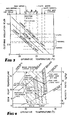
- Fig. 1 is a psychrometric representation of this invention compared with that for a conventional VAV system (dashed lines).
- the equilibrium room condition of a conventional VAV system, 3′ is at a higher room humidity ratio than that for the LFV-HCV room condition, 3.
- the equilibrium condition for the conventional system may rise to a moisture level which lies outside and above the area of acceptable comfort.
- Fig. 2 indicates the importance of relative air motion and level of activity.
- Three bands each traversed by four curves are presented.
- the first band and set of four curves on the right hand side represent thermal comfort conditions for clothing values 0.5 clo respectively for relative air velocities of 1.5 m/s, 0.5 m/s, 0.2 m/s and less than or equal to 0.10 m/s, and mainly sedentary activity typical of that in an office building for which the metabolic rate is 1 met.
- the second band and set of four curves (dashed lines) represent comfort conditions, also for medium clothing (1.0 clo) when sedentary (1 met), while the left hand band and set of chain dashed lines represent comfort conditions for high activity (3 met) and light clothing (0.5 clo).
- the "target zone" within the right hand band is for temperatures about 26°C., clothing 0.5 clo, relative velocity between ⁇ 0.1 m/s and 0.25 m/s and relative humidity between 30% and 60%. At relative velocities above 0.25 m/s, although occupants may feel thermally comfortable, they find the direct effects of the relative velocity disturbing.
- the curves indicate the large influences of activity and attire on the required operative temperature. For example, on a marginal day for a given relative velocity, equal satisfaction is felt by sedentary subjects wearing medium clothing (1.0 clo) in an operative temperature of 24°C and by lightly attired (0.5 clo) subjects performing high activity in an operative temperature of 14°C. Similarly on a hot summer day (right hand and left hand sets of curves which assume that occupants are attired in light clothing) 26°C, 19°C and 14°C are all equally comfortable operative temperature conditions for sedentary (26°C) and for high activity respectively, where the 19°C relates to a very high air velocity (1.5 m/s) and 14°C relates to air velocity ⁇ 0.1 m/s. (The 1.5 m/s figure greatly exceeds ASHRAE recommendations but is shown to illustrate the effect of velocity).
- zone temperatures higher than 26°C in the summer would be considered comfortable.
- comfort within the Standard allows the temperature to increase to 28°C if accompanied by an increase in air movement of 0.275 m/s for each degree C increase in zone temperature.
- the increase in air movement increases the rate of heat transfer from occupants to compensate for the higher temperature air in the room so maintaining comfortable skin temperatures and skin wettedness.
- variable air volume (VAV) system designed for a high-rise offioe building in a temperate climate on the western seaboard of Australia.
- VAV variable air volume
- Many types of air conditioning systems could be employed.
- the superior performance of the LFV-HCV system in maintaining sensible temperatures and humidity ratios which are always within the area of comfort shown in Fig. 1 has already been established, and proven in practice.
- the performance of this already superior low energy multizone LFV-HCV system is now contrasted with a system which incorporates the comfort integration of the present invention into the design.
- a constant supply air temperature is maintained, the coolant flow rate is controlled to maintain the constancy of the supply air temperature, each zone has a thermostat which controls the damper settings to maintain the zone dry bulb temperature, the fan volume flow rate is regulated by one of a number of conventional methods to be compatible with the combined effect of the damper settings in the various zones.
- the LFV-HCV method is different from the conventional VAV system in that: the system operates at a substantially lower face velocity, the coolant velocity is higher, particularly at part load conditions during which the active size of the dehumidifier is reduced, the fin density, circuiting and coolant temperature are important design factors in optimization of performance over the full operating range, the system has a greater capacity to accommodate simultaneous multizone range variation, and the system uses less energy.
- a coil is selected to satisfy the design requirements of an air handling unit to supply a number of zones on a typical level of a high-rise office building located in a temperate climate.
- a room summer dry bulb temperature of 24°C is considered good design when coupled with a system which maintains humidity safely within the comfort areas shown in Fig. 4 (see for example Fig. 1).
- the standard broad comfort zone is shown in dashed lines and is cross-hatched.
- the seleotion provides a room condition of 24°C and 48 per cent relative humidity, and offsets the room sensible heat ratio of 0.87 for the local climatic design condition.
- the selection provides a room condition of 24°C and 57 per cent relative humidity and offsets the room sensible heat ratio of 0.67 for a mild but humid part-load design condition, hereinafter called the humid part-load design condition.
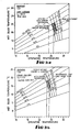
- Fig. 5A is the appropriate figure on which to indicate by an open circle the performance of the LFV-HCV system for peak conditions, without comfort integration.
- Fig. 5B is applicable.
- the part load condition without comfort integration is again indicated by an open circle.
- the room condition lies significantly below the relative velocity for comfort marked "less than 0.1 m/s".
- the air flow velocity must be less than 0.1 m/s.
- the fact that it appears that it must be significantly less than 0.1 m/s is not important as there is no minimum air movement specified as being necessary for thermal comfort if the operative temperature and humidity are satisfactory.
- the performance is within the "acceptable" range.
- the air distribution system is identical for both peak and humid part load operation, the latter of which requires only 65 percent of the air flow volume required by the former. Thus it would be impossible to provide the performances indicated on Fig. 5A as being required for comfort at both peak and humid, or indeed any other part load conditions.
- the air required to offset part loads could not possibly be delivered through the same supply air system in a way which results in a higher relative velocity than that at peak load.
- Fig. 1 of ASHRAE Standards 55-1981 "Thermal Environmental Conditions for Human Occupancy" which provides the basis for Fig 3 indicates the operative temperature range within which 80% of occupants feel comfortable, if the humidity and air movement are also within acceptable limits. For summer conditions assuming clothing insulation is approximately 0.5 clo, the range is 22.8°C to 26.1°C.
- the range is 19.5°C to 23.2°C.
- the room operative temperature is set for peak load conditions to be 26°C and that for humid part load conditions to be 23°C, both of which temperatures are within the respective 80% acceptability ranges.
- These ranges are not mandatory but are selected to allow ready comparison with ASHRAE Standard 55-1981. It should be noted that they can be refined as indicated below.
- Fig. 3 the temperature ranges have been modified to allow for the typically lighter clothing generally worn in Australia, and to accommodate a mix of clothing weights being worn by occupants. This narrows the range of acceptable operative temperatures as indicated by the ranges designated by 'A', 'B' and 'C', in Fig. 3: SUMMER RANGE 'A' is the operative temperature range for 80% acceptability assuming no jackets shed or donned. MARGINAL RANGE 'B' is the similarly restricted comfort range during spring and autumn. WINTER RANGE 'C' is the similarly restricted comfort range for heating.
- Fig. 4 is indicated the area of the ASHRAE Standard 55-1981 charts within which are satisfied the presently acknowledged human comfort conditions for peak (right hand area, 0.5 clo) and for humid part-load (left hand area, 1.0 clo) conditions for the design considered herein.
- a four sided area is marked in with the left side representing the boundary designating a relative velocity of ⁇ 0.1 m/s and the right side a relative velocity of 0.25 m/s to define the range of acceptable relative velocities.
- the top border of the area would be represented by a dew point temperature of 16.6°C and the bottom border by a dew point temperature of 2.7°C.
- Fig. 4 indicates the mutually compatible area for eaoh operating condition by close cross hatching.
- Fig. 4 indicates the peak load and the humid part load performance conditions achieved by allowing flexibility of the room operative temperature. Both conditions then fall within the range in which 80% of the occupants will feel that the conditions are comfortable.
- the left hand column of Table 1 appended to this specification indicates the probable performance of the system with a room thermostat which varies its setting progressively as the sensible load changes from its peak value.
- the system performances at sensible loads which are 65 per cent and 50 per cent of the peak value are shown.
- Figs. 5A and 5B reveal a LFV-HCV-VAV system which is completely compatible with the air conditioning design loads and with human thermal comfort requirements over the full range from peak to the 65 per cent part load condition. Should the system move to a 50 per cent part load condition the chart relative velocity lines would also move slightly to the left to accommodate the heavier clothing which is likely to be worn. The room operative air temperature on the chart would change only from 23°C at 65 per cent part load to 22.8°C at a part load which is 50 per cent of the peak sensible load.
- the required relative velocity for optimum comfort would vary from 0.14 m/s at peak load conditions to 0.12 m/s at 65 per cent part load and to 0.09 m/s at 50 per cent part load. If the relative velocity in the room varies proportionally with the variation in volume flow of air supplied to the room and the room and supply air temperature is kept constant, the relative velocity at the 65 per cent condition would be 0.09 m/s and at 50 per cent, 0.07 m/s. If an increase in humidity is possible without exceeding the comfort level the small discrepancy between the relative velocity optimally desired and to relative velocity achieved could be eliminated by a small increase in the supply air temperature. This contrasts with the incompatibilities found in the earlier example design to the identical specification wherein it was found that a higher relative velocity was required for comfort at part load than that at peak load, an impossible situation.
- the left hand column of Table 1 reveals the superior performance of this method in offsetting the thermal loads, meeting the ventilation loads, and achieving compatibility of the air supply requirements and the relative velocities required for comfort, thus simultaneously optimising performance and the known human comfort principles.
- ASHRAE Standard 55-81 Operating conditions which fall within the comfort area defined by ASHRAE Standard 55-81 may be necessary for creating "that condition of mind in which satisfaction is expressed with the thermal environment", but in most cases they will not be sufficient at all operating load conditions.
- the relative velocity limits restrict acceptable conditions to a narrow band within the general comfort area and, in the example above, it was shown that this narrow band traverses from right to left in response to the changes from peak to minimum load conditions of the air conditioning system. It is this movement which is accommodated by the present invention.
- the aim is the simultaneous energy efficient integration of load, ventilation and human comfort requirements into the design of air conditioning systems.
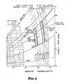
- a Constant Air volume air conditioner comprises a fan 101 which propels air through a dehumidifier 102, a duct 103, and through a conditioned space 104.
- the air is returned to the fan 101 through duct 105 and filters 106.
- Some return air is spilled through one or more controlled or uncontrolled vents 107 and this is replaced with fresh air drawn from outside via a controlled or uncontrolled damper 108.
- Coolant is supplied to the dehumidifier from a chiller plant (not shown).
- the controller controls coolant valves collectively designated 116 and throttle valve 117, as well as spill and ventilation air dampers 107 and 108 if same are active.
- flow control dampers in the supply air duct are not used but the fan motor may have the facility of being switched between two or more speeds under the command of the controller 110.
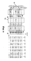
- a Variable Air Volume air conditioner comprises a fan 101 which draws air through a dehumidifier 102 and passes it via a duct 103 and dampers 109 to a conditioned space 104 from which it is returned to the dehumidifier 102 through a duct 105 and filters 106.
- some return air is spilled through one or more controlled or uncontrolled vents 107 and is replaced with fresh air drawn from outside via a controlled or uncontrolled damper 108.
- a spill fan 131 and/or a return air fan 132 and/or return air dampers 133 also in the return air path.
- a supply air damper 125 may be used to effect change in the volume of air delivered by the fan. Preferably such change would be effected by variation of the speed of the fan motor by means of variable speed drive 134.
- the control function is shown in Fig. 6B to be divided between a local zone VAV controller 120 and the Air Handling Unit (AHU) controller 110.
- the two controllers can be combined into a single unit but for clarity here and for larger systems involving several zones it is convenient to locate the zone controllers 120, 220, 320, etc. within the several zones and use a Local Area Network (LAN) 140 or similar communication means to send and receive information to and from the Air Handling Unit controller.
- LAN Local Area Network
- zone VAV controller 120 receives both sensed and processed intelligence from the AHU controller 110, for example information about ambient conditions.
- Zone controller 120 has various manual inputs 119, some of which are set during commissioning of the system, some of which may be set seasonally, and in simple systems some of which may be input at intervals throughout a day. These manual inputs are delineated below in the discussion of the control function. Manual inputs common to all zones are best input directly to the AHU controller, as indicated by 121, and then communicated to all zones via the LAN 140 if a distributed control system, as illustrated, is employed.
- the zone VAV controller could be a conventional thermostat which could be reset manually by the occupants of the zone with the aid of a look-up table of 40 settings for different times of year, levels of activity, sun angle and daily weather forecast.
- the above parameters are either sensed directly or determined by calculation or from information stored in the memory banks of the controllers 110 and 120.
- AHU controller sends information to and receives information from the various zone controllers and maintains communication with the central building system controller 118 via the building Local Area Network (LAN) 140.
- LAN Local Area Network
- Fig. 7 shows diagrammatically one possible configuration of the dehumidifier 102, which comprises three coil rows each with eight passes. It will be seen from Fig. 7 how, even with minimum effective size, the full area of air flow always intercepts active cooling coils. By bypassing flow in some coils (bypass tubes 135), high coolant velocity is maintained (U.S. patent 4942740).
- Each zone served by an air handling unit has a local controller, preferably but not essentially of the programmable type.
- a zone thermostat which is manually adjustable according to a table of settings is required. The following description relates to the use of a programmable controller in the absence of direct sensing of humidity. With humidity sensing the complete comfort equation and predicted mean vote can be solved as detailed earlier in this specifioation.
- Factors of the first type may be sensed by conventional means.
- Factors of the second type may be deduced with the aid of tabulated data.
- the local zone control function requires
- items (b) and (c) require a knowledge of the insulating values of the range of clothing most likely to be being worn by the occupants of the building or of a particular room or zone of the building.
- this may be determined or estimated may be envisaged.
- the occupants may all be required to wear a particular uniform or protective clothing at all times.
- An alternative to use of the observing skills of a doorman would be to estimate the most probable range of clothing being worn.
- the choice of clothing depends on the local culture, on the type of activity, on the time of year and on the early morning weather forecast. Within a given culture and type of activity, the time of year can be determined from the block within the computer or controller and the likely variation about the clothing typical of that time of year is dependent largely on the outside ambient temperature, which can be measured directly. Thus estimates of the likely range of clo values for that particular day may be made. It is good practice to err on the high side in making this estimate during the cooling period as it is usually easier for a well clad person to remove a coat or jacket than for a lightly clad person to find means to keep warm.
- the Air Handling Unit operation is also supervised by a controller.
- this controller is an air-off thermostat, which actuates a valve or valves to adjust the flow of coolant through the dehumidifier coil so to maintain the air-off temperature oonstant, and conventional means of measuring and controlling the air supply volume for a VAV system, or to keep the zone temperature at the set point determined by the zone controller for the CAV system.
- controller it is better practice for the controller to be a programmable controller which receives data from each of the zone controllers and, from a pre-programmed "performance map" for the partioular system, determines the optimum combination of operating point for the air flow fan, active coil area, coolant flow rate and, in the case of a direct expansion (DX) system, the speed of the compressor.
- DX direct expansion
- control system described herein maintains an ongoing record of past actions and of the results of those actions. These data can be used to update and refine the aforesaid performance map.
- the thermal mass of the building fabric will cause the building to respond only slowly to changes in either ambient or room temperature.
- the actual value of Q strans at any given time will be determined by the values of t amb and t a at earlier and usually different times. For this reason these values are stored and then retrieved after a time delay determined by the building time constant.
- the values of Q strans are similarly stored for use in determining the internally generated sensible load in the zone as a function of time. This information is of value to building managers for planning purposes.
- the zone dampers can then be adjusted and information relayed to the AHU controller.
- any discrepancy between the actual damper angle ( ⁇ ), and the angle determined by the controller can be reported immediately the computer based maintenance log.
- Limit alarms may be set and operating costs can be accurately recorded and reported in a readily understandable form.
- the system when used in association with the LFV/HCV method of air conditioning which is the subject of US Patent 4942740, where the occupancy of the zones served by an AHU falls to zero in the evening, the system can be set to run on a maximum dehumidification cycle for a defined period to dry out all ducts, carpets, fabrics and papers. This may be achieved by operating with maximum coolant velocity in the portion of the coil which operates at minimum load, and reducing the face velocity, and hence the air flow volume, to not more than 0.5 metres per second. This procedure eliminates the possibility of mould or bacterial growth in the ductwork and on the building fabric and furnishings.
- the air handling unit (AHU) controller receives information from all local controllers (Fig. 8), adds together the sensible heat loads and the volumes of air demanded, sets the ventilation air quantity on the basis of the needs of the most lightly loaded zone and calculates the best combination of effective dehumidifier size, coolant flow rate, fan speed and main supply air damper position to satisfy the air supply needs of the conditioned zones.
- a time delay ensures that zone dampers are set after the setting of the AHU parameters.
- the compressor speed suction pressure
- the air temperature does not equal the operative temperature and the diurnal and seasonal variations then ideally require a measure of mean radiant temperature, or a direct measurement of operative temperature, to be input to the control system, as indicated above. Nevertheless it is possible to achieve improved results from cheaper options such as allowing sensible load only to determine the room temperature, or the least expensive option of all, relying on the manual adjustment of each zone or room thermostat setting according to tabulated or calculated values derived from the comfort equation.
- the control logic for a CAV system differs from that for the VAV system, Fig. 8, only in the control action which is taken.
- the CAV control system (which will usually be an integral part of the AHU control system) reports to the AHU controller the air temperature required in the zone to achieve the required operative temperature.
- the AHU controller determines from the requirements of other zones, if any the optimum supply air temperature to minimise the reheat throughout the system.
- CAV constant air volume
- the air flow rate is kept constant to all areas served and all areas are sufficiently similar for them to be treated as a single zone.
- the coolant flow rate is throttled with reduction in load, as in the case of the VAV system, but unlike the VAV system the leaving dry bulb temperature from the coil is allowed to rise to maintain a fixed room dry bulb temperature.
- This characteristic of the CAV system has an adverse effect on part load performance.
- the slope of the coil condition curve decreases during part load conditions resulting in reduced dehumidification per unit of cooling; this is precisely the opposite of that which is required to offset the lower sensible heat ratio. It is for this reason that in the past CAV systems have often employed overcooling to satisfy latent heat load and reheating to re-balance the sensible heat load.
- supply air temperature and dehumidifier capacity are initially held substantially constant while the room or zone thermostat or controller is first reset to offset the load and to achieve as closely as possible the required operative temperature. lf insufficient control is available by this means, and coil size is fixed, coolant flow through the dehumidifier is varied to result in a change in supply air temperature. This strategy maintains dehumidification capacity more effectively than does conventional practice. If zone diversity is present, part load rooms or zones are set to maintain a lower temperature than are peak load rooms. Terminal reheat requirements are thus reduced to "trimming".
- zones should, according to good design practice have very nearly the same behaviour of thermal load conditions. Where variations do occur, the zone with the consistently least thermal load would serve as a master zone governing all the zones on the same system and would determine the sensible temperature setting in that "master" zone. However reheat coils would be provided to the associated similar zones to permit adjustment of room temperatures to the same room sensible setting. Only when these other rooms have different mean radiant temperatures would it be necessary too to have variable room temperature thermostats to establish the appropriate room sensible setting given the mean radiant temperature and the seasonal operative temperature.
- the mean radiant temperature is equal to the room sensible temperature in which case the seasonal operative temperature will also be equal to the "master" zone sensible temperature setting and no separate measurement of mean radiant temperature is required. If perimeter zones are involved, measurement of radiant temperature in one zone only, together with predetermined information on diurnal diversity and tabulation of the typical seasonal operative temperatures will allow automatic (or manual) determination of the required room sensible temperature setting without the need for additional globe thermometers.
- the required room sensible temperature will be established through control of the chilled water throttling valve.
- the temperature regulating means and valves controlled by the controller operate in such manner as to limit the range of temperatures within the conditioned space to between 22°C and 27°C as established by comfort standards.
- the systems described use more energy than do the VAV systems for the same duties, they are far less wasteful than the conventional CAV system which seeks to maintain a constant room dry bulb temperature in all rooms at all times.
- the important difference between the conventional CAV system and the CAV system with comfort integration is that in the latter the coil condition curve initially becomes steeper as load decreases so allowing the latent load to be offset without the need for such severe overcooling as that required by the conventional system.
- Table 1 In addition to satisfying thermal loads successfully and achieving optimum comfort, an examination of Table 1 reveals several further advantages contributed by the method of this invention.
- the same system of air conditioning, the LFV HCV-VAV system is compared for the same design specification for the same office building, with and without comfort integration.
- the individual peak load energies which occur at different times in each of the three zones, are equal.
- the air handling unit reaches the simultaneous peak load at 4 pm in the afternoon of a midsummer day.
- the 100% load stage indicated in Table 1 represents the west zone and that this zone consumes 55 per cent of the total air handling unit energy.
- the north, south and east facades are combined to form a second zone which at 4 pm is operating at an average of 60 per cent of the maximum load in this second zone, and is found to consume 35 per cent of the air handling unit energy.
- the interior of the building is the third zone which at the time of the simultaneous peak load is operating at its almost steady state level of ten percent of the air handling unit energy.
Landscapes
- Engineering & Computer Science (AREA)
- Chemical & Material Sciences (AREA)
- Combustion & Propulsion (AREA)
- Mechanical Engineering (AREA)
- General Engineering & Computer Science (AREA)
- Physics & Mathematics (AREA)
- Fluid Mechanics (AREA)
- Air Conditioning Control Device (AREA)
Applications Claiming Priority (2)
| Application Number | Priority Date | Filing Date | Title |
|---|---|---|---|
| AUPJ603589 | 1989-08-30 | ||
| AU6035/89 | 1989-08-30 |
Publications (2)
| Publication Number | Publication Date |
|---|---|
| EP0415747A2 true EP0415747A2 (fr) | 1991-03-06 |
| EP0415747A3 EP0415747A3 (en) | 1992-01-15 |
Family
ID=3774145
Family Applications (1)
| Application Number | Title | Priority Date | Filing Date |
|---|---|---|---|
| EP19900309473 Withdrawn EP0415747A3 (en) | 1989-08-30 | 1990-08-30 | Comfort integration and energy efficient method of air conditioning |
Country Status (7)
| Country | Link |
|---|---|
| US (1) | US5058388A (fr) |
| EP (1) | EP0415747A3 (fr) |
| JP (1) | JPH0399150A (fr) |
| KR (1) | KR910005004A (fr) |
| CN (1) | CN1050762A (fr) |
| CA (1) | CA2024221A1 (fr) |
| NZ (1) | NZ235064A (fr) |
Cited By (26)
| Publication number | Priority date | Publication date | Assignee | Title |
|---|---|---|---|---|
| EP0643271A1 (fr) * | 1993-09-10 | 1995-03-15 | Fa. Rud. Otto Meyer | Procédé pour la régulation de la température et de l'humidité dans les enceintes utilisant une installation de climatisation d'air |
| GB2308679B (en) * | 1995-12-23 | 2000-06-21 | Honeywell Control Syst | Control apparatus and method |
| EP1355212A1 (fr) * | 2002-04-16 | 2003-10-22 | Honeywell Control Systems Ltd. | Système de regulation de température |
| WO2007062843A1 (fr) * | 2005-12-01 | 2007-06-07 | Black Box Gmbh & Co. Kg | Regulation de reference de densite atmospherique |
| WO2009007727A1 (fr) * | 2007-07-10 | 2009-01-15 | Davies Philip J | Dispositif de commande de système de transfert thermique |
| WO2011088270A3 (fr) * | 2010-01-13 | 2011-11-10 | Gtr Technologies, Inc. | Système et procédé de commande de ventilation |
| WO2012024534A3 (fr) * | 2010-08-20 | 2012-05-31 | Ecofactor, Inc. | Système et procédé pour optimiser l'utilisation de climatiseurs et radiateurs portatifs électriques |
| EP2508811A1 (fr) * | 2011-04-08 | 2012-10-10 | Zehnder Verkaufs- und Verwaltungs AG | Dispositif de détermination d'un débit volumique transporté par un ventilateur |
| US8412488B2 (en) | 2007-08-03 | 2013-04-02 | Ecofactor, Inc. | System and method for using a network of thermostats as tool to verify peak demand reduction |
| US8423322B2 (en) | 2007-09-17 | 2013-04-16 | Ecofactor, Inc. | System and method for evaluating changes in the efficiency of an HVAC system |
| CN103182645A (zh) * | 2013-03-01 | 2013-07-03 | 杭州沃镭科技有限公司 | 一种汽车空气干燥器装配及检测生产线 |
| US8498753B2 (en) | 2009-05-08 | 2013-07-30 | Ecofactor, Inc. | System, method and apparatus for just-in-time conditioning using a thermostat |
| US8556188B2 (en) | 2010-05-26 | 2013-10-15 | Ecofactor, Inc. | System and method for using a mobile electronic device to optimize an energy management system |
| US8596550B2 (en) | 2009-05-12 | 2013-12-03 | Ecofactor, Inc. | System, method and apparatus for identifying manual inputs to and adaptive programming of a thermostat |
| US8740100B2 (en) | 2009-05-11 | 2014-06-03 | Ecofactor, Inc. | System, method and apparatus for dynamically variable compressor delay in thermostat to reduce energy consumption |
| US8751186B2 (en) | 2007-09-17 | 2014-06-10 | Ecofactor, Inc. | System and method for calculating the thermal mass of a building |
| KR20150064346A (ko) * | 2013-12-03 | 2015-06-11 | 삼성전자주식회사 | 공조장치 또는 공조시스템의 온도 제어장치 및 방법 |
| US9134710B2 (en) | 2008-07-07 | 2015-09-15 | Ecofactor, Inc. | System and method for using ramped setpoint temperature variation with networked thermostats to improve efficiency |
| US9244470B2 (en) | 2008-07-14 | 2016-01-26 | Ecofactor, Inc. | System and method for using a wireless device as a sensor for an energy management system |
| FR3035709A1 (fr) * | 2015-04-30 | 2016-11-04 | Thermor Pacific | Procede de regulation d'un appareil de chauffage et/ou de climatisation en fonction du niveau d'activite et appareil de chauffage et/ou de climatisation associe |
| US10048706B2 (en) | 2012-06-14 | 2018-08-14 | Ecofactor, Inc. | System and method for optimizing use of individual HVAC units in multi-unit chiller-based systems |
| WO2019014605A1 (fr) | 2017-07-14 | 2019-01-17 | Ebtron, Inc. | Dispositifs de capteurs de flux d'air, systèmes et procédés |
| EP3578887A1 (fr) * | 2018-06-07 | 2019-12-11 | Koninklijke Philips N.V. | Système et procédé de contrôle de la qualité de l'air |
| US10584890B2 (en) | 2010-05-26 | 2020-03-10 | Ecofactor, Inc. | System and method for using a mobile electronic device to optimize an energy management system |
| WO2021086684A1 (fr) * | 2019-10-31 | 2021-05-06 | Carrier Corporation | Procédé de surveillance des performances de chauffage, ventilation et climatisation (hvac) |
| CN113446712A (zh) * | 2021-06-09 | 2021-09-28 | 海信(山东)空调有限公司 | 空调器的控制方法及装置、空调器和计算机可读存储介质 |
Families Citing this family (159)
| Publication number | Priority date | Publication date | Assignee | Title |
|---|---|---|---|---|
| US5436852A (en) * | 1990-09-21 | 1995-07-25 | Yamatake-Honeywell Co., Ltd. | Method and apparatus for calculating predicted mean thermal sensitivity |
| WO1992020973A1 (fr) * | 1991-05-24 | 1992-11-26 | Luminis Pty. Ltd. | Climatisation pour climats humides |
| US5351855A (en) * | 1992-04-02 | 1994-10-04 | Honeywell Inc. | Humidistat reset control |
| US5303561A (en) * | 1992-10-14 | 1994-04-19 | Copeland Corporation | Control system for heat pump having humidity responsive variable speed fan |
| US5446677A (en) * | 1994-04-28 | 1995-08-29 | Johnson Service Company | Diagnostic system for use in an environment control network |
| US5555195A (en) * | 1994-07-22 | 1996-09-10 | Johnson Service Company | Controller for use in an environment control network capable of storing diagnostic information |
| US5682329A (en) * | 1994-07-22 | 1997-10-28 | Johnson Service Company | On-line monitoring of controllers in an environment control network |
| DE19719792B4 (de) * | 1997-05-10 | 2004-03-25 | Behr Gmbh & Co. | Verfahren und Vorrichtung zur Regulierung der Temperatur eines Mediums |
| US6059652A (en) * | 1997-12-16 | 2000-05-09 | Summit Polymers, Inc. | Register for a vehicle |
| BR0007811B1 (pt) | 1999-01-12 | 2009-01-13 | sistema de compressço a vapor e mÉtodo para operar o sistema. | |
| CZ20012527A3 (cs) | 1999-01-12 | 2002-07-17 | Xdx, Llc | Parní kompresní systém a způsob jeho provozování |
| US6185958B1 (en) | 1999-11-02 | 2001-02-13 | Xdx, Llc | Vapor compression system and method |
| US6314747B1 (en) | 1999-01-12 | 2001-11-13 | Xdx, Llc | Vapor compression system and method |
| US6505475B1 (en) | 1999-08-20 | 2003-01-14 | Hudson Technologies Inc. | Method and apparatus for measuring and improving efficiency in refrigeration systems |
| US6401470B1 (en) | 2000-09-14 | 2002-06-11 | Xdx, Llc | Expansion device for vapor compression system |
| US6393851B1 (en) | 2000-09-14 | 2002-05-28 | Xdx, Llc | Vapor compression system |
| US6324854B1 (en) * | 2000-11-22 | 2001-12-04 | Copeland Corporation | Air-conditioning servicing system and method |
| US6415617B1 (en) * | 2001-01-10 | 2002-07-09 | Johnson Controls Technology Company | Model based economizer control of an air handling unit |
| US6892546B2 (en) | 2001-05-03 | 2005-05-17 | Emerson Retail Services, Inc. | System for remote refrigeration monitoring and diagnostics |
| US6668240B2 (en) | 2001-05-03 | 2003-12-23 | Emerson Retail Services Inc. | Food quality and safety model for refrigerated food |
| AU2002365545B2 (en) * | 2001-11-30 | 2008-08-14 | National University Of Singapore | Single-coil twin-fan variable-air volume (VAV) system for energy-efficient conditioning of independent fresh and return air streams |
| US6889173B2 (en) | 2002-10-31 | 2005-05-03 | Emerson Retail Services Inc. | System for monitoring optimal equipment operating parameters |
| US8463441B2 (en) | 2002-12-09 | 2013-06-11 | Hudson Technologies, Inc. | Method and apparatus for optimizing refrigeration systems |
| DK1664638T3 (da) | 2003-08-25 | 2009-08-17 | Computer Process Controls Inc | Kölestyresystem |
| WO2005065355A2 (fr) * | 2003-12-30 | 2005-07-21 | Copeland Corporation | Systeme de diagnostic et de protection de compresseur |
| US7412842B2 (en) | 2004-04-27 | 2008-08-19 | Emerson Climate Technologies, Inc. | Compressor diagnostic and protection system |
| US20060010891A1 (en) * | 2004-07-15 | 2006-01-19 | York International Corporation | HVAC&R humidity control system and method |
| US7275377B2 (en) | 2004-08-11 | 2007-10-02 | Lawrence Kates | Method and apparatus for monitoring refrigerant-cycle systems |
| EP1851959B1 (fr) | 2005-02-21 | 2012-04-11 | Computer Process Controls, Inc. | Systeme de surveillance et de commande d'entreprise |
| US7665315B2 (en) | 2005-10-21 | 2010-02-23 | Emerson Retail Services, Inc. | Proofing a refrigeration system operating state |
| US7594407B2 (en) | 2005-10-21 | 2009-09-29 | Emerson Climate Technologies, Inc. | Monitoring refrigerant in a refrigeration system |
| US7752853B2 (en) | 2005-10-21 | 2010-07-13 | Emerson Retail Services, Inc. | Monitoring refrigerant in a refrigeration system |
| US7752854B2 (en) | 2005-10-21 | 2010-07-13 | Emerson Retail Services, Inc. | Monitoring a condenser in a refrigeration system |
| US7596959B2 (en) | 2005-10-21 | 2009-10-06 | Emerson Retail Services, Inc. | Monitoring compressor performance in a refrigeration system |
| US8590325B2 (en) | 2006-07-19 | 2013-11-26 | Emerson Climate Technologies, Inc. | Protection and diagnostic module for a refrigeration system |
| US20080216494A1 (en) | 2006-09-07 | 2008-09-11 | Pham Hung M | Compressor data module |
| US7584021B2 (en) * | 2006-11-08 | 2009-09-01 | Hewlett-Packard Development Company, L.P. | Energy efficient CRAC unit operation using heat transfer levels |
| KR20090104063A (ko) * | 2007-01-17 | 2009-10-05 | 다이킨 고교 가부시키가이샤 | 공조 제어 시스템 |
| US20080217419A1 (en) * | 2007-03-06 | 2008-09-11 | Ranco Incorporated Of Delaware | Communicating Environmental Control System |
| US7774102B2 (en) * | 2007-06-22 | 2010-08-10 | Emerson Electric Co. | System including interactive controllers for controlling operation of climate control system |
| US20090037142A1 (en) | 2007-07-30 | 2009-02-05 | Lawrence Kates | Portable method and apparatus for monitoring refrigerant-cycle systems |
| US8393169B2 (en) | 2007-09-19 | 2013-03-12 | Emerson Climate Technologies, Inc. | Refrigeration monitoring system and method |
| US9140728B2 (en) | 2007-11-02 | 2015-09-22 | Emerson Climate Technologies, Inc. | Compressor sensor module |
| US8160827B2 (en) | 2007-11-02 | 2012-04-17 | Emerson Climate Technologies, Inc. | Compressor sensor module |
| KR100830095B1 (ko) * | 2007-11-12 | 2008-05-20 | 충남대학교산학협력단 | 냉방부하 예측방법 |
| US7821218B2 (en) * | 2008-04-22 | 2010-10-26 | Emerson Electric Co. | Universal apparatus and method for configurably controlling a heating or cooling system |
| CN101965492B (zh) | 2008-05-15 | 2015-02-25 | Xdx创新制冷有限公司 | 减少除霜的浪涌式蒸汽压缩传热系统 |
| US9261888B2 (en) | 2008-10-27 | 2016-02-16 | Lennox Industries Inc. | System and method of use for a user interface dashboard of a heating, ventilation and air conditioning network |
| US9152155B2 (en) | 2008-10-27 | 2015-10-06 | Lennox Industries Inc. | Device abstraction system and method for a distributed-architecture heating, ventilation and air conditioning system |
| US8855825B2 (en) | 2008-10-27 | 2014-10-07 | Lennox Industries Inc. | Device abstraction system and method for a distributed-architecture heating, ventilation and air conditioning system |
| US8442693B2 (en) | 2008-10-27 | 2013-05-14 | Lennox Industries, Inc. | System and method of use for a user interface dashboard of a heating, ventilation and air conditioning network |
| US9432208B2 (en) | 2008-10-27 | 2016-08-30 | Lennox Industries Inc. | Device abstraction system and method for a distributed architecture heating, ventilation and air conditioning system |
| US8548630B2 (en) | 2008-10-27 | 2013-10-01 | Lennox Industries, Inc. | Alarm and diagnostics system and method for a distributed-architecture heating, ventilation and air conditioning network |
| US8977794B2 (en) | 2008-10-27 | 2015-03-10 | Lennox Industries, Inc. | Communication protocol system and method for a distributed-architecture heating, ventilation and air conditioning network |
| US8774210B2 (en) * | 2008-10-27 | 2014-07-08 | Lennox Industries, Inc. | Communication protocol system and method for a distributed-architecture heating, ventilation and air conditioning network |
| US8725298B2 (en) | 2008-10-27 | 2014-05-13 | Lennox Industries, Inc. | Alarm and diagnostics system and method for a distributed architecture heating, ventilation and conditioning network |
| US8352081B2 (en) | 2008-10-27 | 2013-01-08 | Lennox Industries Inc. | Communication protocol system and method for a distributed-architecture heating, ventilation and air conditioning network |
| US8437878B2 (en) | 2008-10-27 | 2013-05-07 | Lennox Industries Inc. | Alarm and diagnostics system and method for a distributed architecture heating, ventilation and air conditioning network |
| US9678486B2 (en) | 2008-10-27 | 2017-06-13 | Lennox Industries Inc. | Device abstraction system and method for a distributed-architecture heating, ventilation and air conditioning system |
| US8744629B2 (en) | 2008-10-27 | 2014-06-03 | Lennox Industries Inc. | System and method of use for a user interface dashboard of a heating, ventilation and air conditioning network |
| US8798796B2 (en) | 2008-10-27 | 2014-08-05 | Lennox Industries Inc. | General control techniques in a heating, ventilation and air conditioning network |
| US8564400B2 (en) | 2008-10-27 | 2013-10-22 | Lennox Industries, Inc. | Communication protocol system and method for a distributed-architecture heating, ventilation and air conditioning network |
| US8463442B2 (en) | 2008-10-27 | 2013-06-11 | Lennox Industries, Inc. | Alarm and diagnostics system and method for a distributed architecture heating, ventilation and air conditioning network |
| US8874815B2 (en) | 2008-10-27 | 2014-10-28 | Lennox Industries, Inc. | Communication protocol system and method for a distributed architecture heating, ventilation and air conditioning network |
| US8994539B2 (en) | 2008-10-27 | 2015-03-31 | Lennox Industries, Inc. | Alarm and diagnostics system and method for a distributed-architecture heating, ventilation and air conditioning network |
| US8463443B2 (en) | 2008-10-27 | 2013-06-11 | Lennox Industries, Inc. | Memory recovery scheme and data structure in a heating, ventilation and air conditioning network |
| US8600559B2 (en) | 2008-10-27 | 2013-12-03 | Lennox Industries Inc. | Method of controlling equipment in a heating, ventilation and air conditioning network |
| US9377768B2 (en) | 2008-10-27 | 2016-06-28 | Lennox Industries Inc. | Memory recovery scheme and data structure in a heating, ventilation and air conditioning network |
| US9651925B2 (en) | 2008-10-27 | 2017-05-16 | Lennox Industries Inc. | System and method for zoning a distributed-architecture heating, ventilation and air conditioning network |
| US8255086B2 (en) | 2008-10-27 | 2012-08-28 | Lennox Industries Inc. | System recovery in a heating, ventilation and air conditioning network |
| US8560125B2 (en) | 2008-10-27 | 2013-10-15 | Lennox Industries | Communication protocol system and method for a distributed-architecture heating, ventilation and air conditioning network |
| US8655491B2 (en) | 2008-10-27 | 2014-02-18 | Lennox Industries Inc. | Alarm and diagnostics system and method for a distributed architecture heating, ventilation and air conditioning network |
| US8452456B2 (en) | 2008-10-27 | 2013-05-28 | Lennox Industries Inc. | System and method of use for a user interface dashboard of a heating, ventilation and air conditioning network |
| US9325517B2 (en) | 2008-10-27 | 2016-04-26 | Lennox Industries Inc. | Device abstraction system and method for a distributed-architecture heating, ventilation and air conditioning system |
| US8615326B2 (en) | 2008-10-27 | 2013-12-24 | Lennox Industries Inc. | System and method of use for a user interface dashboard of a heating, ventilation and air conditioning network |
| US8655490B2 (en) | 2008-10-27 | 2014-02-18 | Lennox Industries, Inc. | System and method of use for a user interface dashboard of a heating, ventilation and air conditioning network |
| US8437877B2 (en) | 2008-10-27 | 2013-05-07 | Lennox Industries Inc. | System recovery in a heating, ventilation and air conditioning network |
| US8295981B2 (en) | 2008-10-27 | 2012-10-23 | Lennox Industries Inc. | Device commissioning in a heating, ventilation and air conditioning network |
| US8762666B2 (en) | 2008-10-27 | 2014-06-24 | Lennox Industries, Inc. | Backup and restoration of operation control data in a heating, ventilation and air conditioning network |
| US9268345B2 (en) | 2008-10-27 | 2016-02-23 | Lennox Industries Inc. | System and method of use for a user interface dashboard of a heating, ventilation and air conditioning network |
| US8661165B2 (en) | 2008-10-27 | 2014-02-25 | Lennox Industries, Inc. | Device abstraction system and method for a distributed architecture heating, ventilation and air conditioning system |
| US8239066B2 (en) | 2008-10-27 | 2012-08-07 | Lennox Industries Inc. | System and method of use for a user interface dashboard of a heating, ventilation and air conditioning network |
| US8694164B2 (en) | 2008-10-27 | 2014-04-08 | Lennox Industries, Inc. | Interactive user guidance interface for a heating, ventilation and air conditioning system |
| US8802981B2 (en) | 2008-10-27 | 2014-08-12 | Lennox Industries Inc. | Flush wall mount thermostat and in-set mounting plate for a heating, ventilation and air conditioning system |
| US9632490B2 (en) | 2008-10-27 | 2017-04-25 | Lennox Industries Inc. | System and method for zoning a distributed architecture heating, ventilation and air conditioning network |
| US8352080B2 (en) | 2008-10-27 | 2013-01-08 | Lennox Industries Inc. | Communication protocol system and method for a distributed-architecture heating, ventilation and air conditioning network |
| US8788100B2 (en) | 2008-10-27 | 2014-07-22 | Lennox Industries Inc. | System and method for zoning a distributed-architecture heating, ventilation and air conditioning network |
| US8543243B2 (en) | 2008-10-27 | 2013-09-24 | Lennox Industries, Inc. | System and method of use for a user interface dashboard of a heating, ventilation and air conditioning network |
| US8892797B2 (en) | 2008-10-27 | 2014-11-18 | Lennox Industries Inc. | Communication protocol system and method for a distributed-architecture heating, ventilation and air conditioning network |
| US8433446B2 (en) | 2008-10-27 | 2013-04-30 | Lennox Industries, Inc. | Alarm and diagnostics system and method for a distributed-architecture heating, ventilation and air conditioning network |
| US8452906B2 (en) | 2008-10-27 | 2013-05-28 | Lennox Industries, Inc. | Communication protocol system and method for a distributed-architecture heating, ventilation and air conditioning network |
| US8600558B2 (en) | 2008-10-27 | 2013-12-03 | Lennox Industries Inc. | System recovery in a heating, ventilation and air conditioning network |
| US9562700B2 (en) * | 2009-02-20 | 2017-02-07 | Mitsubishi Electric Corporation | Use-side unit and air conditioner |
| US8903553B1 (en) | 2009-05-01 | 2014-12-02 | Comverge, Inc. | Method and system for controlling unitary air conditioners for reducing peak loads |
| BRPI1014993A8 (pt) | 2009-05-29 | 2016-10-18 | Emerson Retail Services Inc | sistema e método para o monitoramento e avaliação de modificações de parâmetro de operação de equipamento |
| US8239068B1 (en) | 2009-06-26 | 2012-08-07 | Comverge, Inc. | Method and system for cooperative powering of unitary air conditioners |
| USD648642S1 (en) | 2009-10-21 | 2011-11-15 | Lennox Industries Inc. | Thin cover plate for an electronic system controller |
| USD648641S1 (en) | 2009-10-21 | 2011-11-15 | Lennox Industries Inc. | Thin cover plate for an electronic system controller |
| US8260444B2 (en) | 2010-02-17 | 2012-09-04 | Lennox Industries Inc. | Auxiliary controller of a HVAC system |
| CN102192569B (zh) * | 2010-03-11 | 2013-08-07 | 珠海格力电器股份有限公司 | 基于热舒适区的空调控制方法 |
| JP5525960B2 (ja) * | 2010-08-10 | 2014-06-18 | アズビル株式会社 | 空調制御装置および方法 |
| US9906029B2 (en) | 2010-12-16 | 2018-02-27 | Lennox Industries Inc. | Priority-based energy management |
| JP5561196B2 (ja) | 2011-02-08 | 2014-07-30 | 株式会社デンソー | シート空調装置を備えた車両用空調装置 |
| WO2012118830A2 (fr) | 2011-02-28 | 2012-09-07 | Arensmeier Jeffrey N | Solutions de contrôle et de diagnostic d'un système hvac destinées à des habitations |
| US8700227B2 (en) * | 2011-03-11 | 2014-04-15 | Honeywell International Inc. | Room thermal comfort monitor |
| TWI432681B (zh) * | 2011-04-01 | 2014-04-01 | Delta Electronics Inc | 具有手動除濕功能之空調裝置及其操作方法 |
| US8964338B2 (en) | 2012-01-11 | 2015-02-24 | Emerson Climate Technologies, Inc. | System and method for compressor motor protection |
| WO2013105087A1 (fr) * | 2012-01-12 | 2013-07-18 | Lncon Systems Ltd. | Régulation de refroidisseur |
| US9892472B2 (en) * | 2012-02-27 | 2018-02-13 | Siemens Corporation | Cost optimization for buildings with hybrid ventilation systems |
| US9480177B2 (en) | 2012-07-27 | 2016-10-25 | Emerson Climate Technologies, Inc. | Compressor protection module |
| US9310439B2 (en) | 2012-09-25 | 2016-04-12 | Emerson Climate Technologies, Inc. | Compressor having a control and diagnostic module |
| US9551504B2 (en) | 2013-03-15 | 2017-01-24 | Emerson Electric Co. | HVAC system remote monitoring and diagnosis |
| US9803902B2 (en) | 2013-03-15 | 2017-10-31 | Emerson Climate Technologies, Inc. | System for refrigerant charge verification using two condenser coil temperatures |
| AU2014229103B2 (en) | 2013-03-15 | 2016-12-08 | Emerson Electric Co. | HVAC system remote monitoring and diagnosis |
| AU2014248049B2 (en) | 2013-04-05 | 2018-06-07 | Emerson Climate Technologies, Inc. | Heat-pump system with refrigerant charge diagnostics |
| US9714770B2 (en) * | 2014-04-01 | 2017-07-25 | Hoffman Enclosures, Inc. | Fresh air cooling device |
| JP5879516B2 (ja) * | 2014-04-04 | 2016-03-08 | パナソニックIpマネジメント株式会社 | 空気調和機 |
| BR112017021842A2 (pt) | 2014-11-20 | 2018-07-10 | Univ Arizona State | sistemas e métodos para geração de água líquida a partir do ar |
| CN104406256A (zh) * | 2014-12-10 | 2015-03-11 | 安徽金鑫实验设备科技有限公司 | 一种实验室空气净化系统 |
| US10166841B2 (en) * | 2015-09-09 | 2019-01-01 | International Truck Intellectual Property Company, Llc | Vehicle climate control system |
| US10161662B2 (en) | 2015-11-30 | 2018-12-25 | Lennox Industries LLC | Method and apparatus for reheat dehumidification with variable speed outdoor fan |
| US10386089B2 (en) * | 2015-11-30 | 2019-08-20 | Lennox Industries Inc. | Method and apparatus for re-heat dehumidification utilizing a variable speed compressor system |
| US10337755B2 (en) | 2015-11-30 | 2019-07-02 | Lennox Industries LLC | Method and apparatus for reheat dehumidification with variable air volume |
| EP3208561A1 (fr) | 2016-02-16 | 2017-08-23 | Lennox Industries Inc. | Procédé et appareil pour déshumidification pré-chauffée utilisant un système de compresseur à vitesse variable |
| TWI718284B (zh) | 2016-04-07 | 2021-02-11 | 美商零質量純水股份有限公司 | 太陽能加熱單元 |
| TWI817925B (zh) | 2016-05-20 | 2023-10-11 | 美商資源環球公司 | 用於水萃取控制之系統及方法及水產生之網路 |
| CN107462390A (zh) * | 2016-06-06 | 2017-12-12 | 苏州中尧节能环保设备有限公司 | 一种双流路多功能流动与换热试验装置 |
| US10295217B2 (en) | 2016-06-09 | 2019-05-21 | Lennox Industries Inc. | Method and apparatus for optimizing latent capacity of a variable speed compressor system |
| US10072862B2 (en) | 2016-06-09 | 2018-09-11 | Lennox Industries Inc. | Method and system for optimizing a speed of at least one of a variable speed compressor and a variable speed circulation fan to improve latent capacity |
| CN106678991B (zh) * | 2017-03-07 | 2022-05-10 | 重庆大学 | 一种适用于辐射空调的新风机组调控系统及其控制方法 |
| CN107166636B (zh) * | 2017-04-26 | 2019-10-08 | 北京小米移动软件有限公司 | 空调控制方法及装置 |
| WO2019014599A2 (fr) | 2017-07-14 | 2019-01-17 | Zero Mass Water, Inc. | Systèmes de traitement commandé d'eau avec de l'ozone et procédés associés |
| MX2020002482A (es) | 2017-09-05 | 2021-02-15 | Zero Mass Water Inc | Sistemas y metodos para administrar la produccion y distribucion de agua liquida extraida del aire. |
| US11384517B2 (en) | 2017-09-05 | 2022-07-12 | Source Global, PBC | Systems and methods to produce liquid water extracted from air |
| CN107560082A (zh) * | 2017-09-11 | 2018-01-09 | 珠海格力电器股份有限公司 | 一种自适应空调器及智能控制方法 |
| AU2018346803B2 (en) | 2017-10-06 | 2024-03-14 | Source Global, PBC | Systems for generating water with waste heat and related methods therefor |
| CA3023404A1 (fr) | 2017-11-09 | 2019-05-09 | William D. Carson | Systeme de controle environnemental de gestion de la croissance de vegetaux |
| AU2018380168B2 (en) | 2017-12-06 | 2023-11-02 | Source Global, PBC | Systems for constructing hierarchical training data sets for use with machine-learning and related methods therefor |
| CN108317692B (zh) * | 2018-01-26 | 2020-03-31 | 青岛海尔空调器有限总公司 | 基于穿衣补偿的温冷感空调器控制方法和空调器 |
| CN108413589B (zh) * | 2018-01-26 | 2020-02-04 | 青岛海尔空调器有限总公司 | 一种基于温冷感的空调器控制方法和空调器 |
| US11160223B2 (en) | 2018-02-18 | 2021-11-02 | Source Global, PBC | Systems for generating water for a container farm and related methods therefor |
| JP7062475B2 (ja) * | 2018-03-14 | 2022-05-06 | 株式会社東芝 | 空調制御装置、空調システム、空調制御方法及びプログラム |
| CN108644955B (zh) * | 2018-04-12 | 2020-07-14 | 东南大学 | 一种地板供冷复合置换通风系统的空间湿度控制方法 |
| US11268729B2 (en) * | 2018-05-07 | 2022-03-08 | Johnson Controls Tyco IP Holdings LLP | Building management system with apparent indoor temperature and comfort mapping |
| AU2019265024A1 (en) | 2018-05-11 | 2020-12-03 | Source Global, PBC | Systems for generating water using exogenously generated heat, exogenously generated electricity, and exhaust process fluids and related methods therefor |
| AU2019359894A1 (en) | 2018-10-19 | 2021-06-10 | Source Global, PBC | Systems and methods for generating liquid water using highly efficient techniques that optimize production |
| US20200124566A1 (en) | 2018-10-22 | 2020-04-23 | Zero Mass Water, Inc. | Systems and methods for detecting and measuring oxidizing compounds in test fluids |
| AU2020262259A1 (en) | 2019-04-22 | 2021-12-16 | Source Global, PBC | Water vapor adsorption air drying system and method for generating liquid water from air |
| CN110375406B (zh) * | 2019-07-29 | 2021-11-26 | 江苏碳元绿色建筑科技有限公司 | 一种辐射空调系统 |
| CN110596181B (zh) * | 2019-09-26 | 2022-04-05 | 安徽高梵电子商务有限公司 | 一种羽绒服保暖性能检测验收方法 |
| KR20220113719A (ko) * | 2019-12-23 | 2022-08-16 | 베스텔 일렉트로닉 사나이 베 티카레트 에이에스 | 자기 냉각을 위한 장치 및 가전 제품 |
| US11692729B2 (en) * | 2020-07-01 | 2023-07-04 | Haier Us Appliance Solutions, Inc. | Single-package air conditioner and methods of operation |
| CN112797493B (zh) * | 2021-01-13 | 2023-12-22 | 青岛海信日立空调系统有限公司 | 一种新风空调器及其控制方法 |
| US11814820B2 (en) | 2021-01-19 | 2023-11-14 | Source Global, PBC | Systems and methods for generating water from air |
| CN112859973A (zh) * | 2021-02-02 | 2021-05-28 | 邱子轩 | 一种防护服内环境降温除湿的方法及装置 |
| CN113606755B (zh) * | 2021-07-30 | 2022-08-30 | 浙江容大电力工程有限公司 | 基于需求响应的空调管理方法 |
| CN113932418A (zh) * | 2021-11-16 | 2022-01-14 | 广东百朗新风系统有限公司 | 新风空调除湿机及其控制方法 |
| US11815275B2 (en) * | 2022-01-18 | 2023-11-14 | Radiant Innovation Inc. | Portable electronic device for providing graphical information obtained by combining temperature humidity index with comfortability index |
| CN114893890B (zh) * | 2022-05-07 | 2024-01-30 | 合肥美的暖通设备有限公司 | 空调器及其控制方法、装置、组件和计算机设备 |
Citations (2)
| Publication number | Priority date | Publication date | Assignee | Title |
|---|---|---|---|---|
| US2828464A (en) * | 1953-10-21 | 1958-03-25 | Stone J & Co Ltd | Control of air-conditioning apparatus |
| DE2852761A1 (de) * | 1977-12-07 | 1979-10-25 | Hitachi Ltd | Steueranordnung fuer klimageraet |
Family Cites Families (3)
| Publication number | Priority date | Publication date | Assignee | Title |
|---|---|---|---|---|
| AU530554B2 (en) * | 1979-03-28 | 1983-07-21 | Luminis Pty Limited | Method of air conditioning |
| AU597757B2 (en) * | 1986-11-24 | 1990-06-07 | Luminis Pty Limited | Air conditioner and method of dehumidifier control |
| US4841733A (en) * | 1988-01-07 | 1989-06-27 | Dussault David R | Dri-Pc humidity and temperature controller |
-
1990
- 1990-08-27 US US07/573,233 patent/US5058388A/en not_active Expired - Fee Related
- 1990-08-28 NZ NZ235064A patent/NZ235064A/xx unknown
- 1990-08-29 CA CA002024221A patent/CA2024221A1/fr not_active Abandoned
- 1990-08-30 JP JP2229539A patent/JPH0399150A/ja active Pending
- 1990-08-30 KR KR1019900013478A patent/KR910005004A/ko not_active Application Discontinuation
- 1990-08-30 CN CN90108235A patent/CN1050762A/zh active Pending
- 1990-08-30 EP EP19900309473 patent/EP0415747A3/en not_active Withdrawn
Patent Citations (2)
| Publication number | Priority date | Publication date | Assignee | Title |
|---|---|---|---|---|
| US2828464A (en) * | 1953-10-21 | 1958-03-25 | Stone J & Co Ltd | Control of air-conditioning apparatus |
| DE2852761A1 (de) * | 1977-12-07 | 1979-10-25 | Hitachi Ltd | Steueranordnung fuer klimageraet |
Cited By (55)
| Publication number | Priority date | Publication date | Assignee | Title |
|---|---|---|---|---|
| EP0643271A1 (fr) * | 1993-09-10 | 1995-03-15 | Fa. Rud. Otto Meyer | Procédé pour la régulation de la température et de l'humidité dans les enceintes utilisant une installation de climatisation d'air |
| GB2308679B (en) * | 1995-12-23 | 2000-06-21 | Honeywell Control Syst | Control apparatus and method |
| EP1355212A1 (fr) * | 2002-04-16 | 2003-10-22 | Honeywell Control Systems Ltd. | Système de regulation de température |
| WO2007062843A1 (fr) * | 2005-12-01 | 2007-06-07 | Black Box Gmbh & Co. Kg | Regulation de reference de densite atmospherique |
| EP1954988A1 (fr) | 2005-12-01 | 2008-08-13 | Black Box Gmbh & CO. KG. | Regulation de reference de densite atmospherique |
| JP2009517624A (ja) * | 2005-12-01 | 2009-04-30 | ブラック ボックス ゲーエムベーハー アンド コー.カーゲー | 空気密度基準制御 |
| US8554375B2 (en) | 2005-12-01 | 2013-10-08 | Delta Green Box Patent Gmbh & Co. Kg | Air density comparison control |
| WO2009007727A1 (fr) * | 2007-07-10 | 2009-01-15 | Davies Philip J | Dispositif de commande de système de transfert thermique |
| GB2459994A (en) * | 2007-07-10 | 2009-11-18 | Philip J Davies | Heat Transfer System Controller |
| US8738327B2 (en) | 2007-08-03 | 2014-05-27 | Ecofactor, Inc. | System and method for using a network of thermostats as tool to verify peak demand reduction |
| US8412488B2 (en) | 2007-08-03 | 2013-04-02 | Ecofactor, Inc. | System and method for using a network of thermostats as tool to verify peak demand reduction |
| US9939333B2 (en) | 2007-09-17 | 2018-04-10 | Ecofactor, Inc. | System and method for evaluating changes in the efficiency of an HVAC system |
| US9057649B2 (en) | 2007-09-17 | 2015-06-16 | Ecofactor, Inc. | System and method for evaluating changes in the efficiency of an HVAC system |
| US8423322B2 (en) | 2007-09-17 | 2013-04-16 | Ecofactor, Inc. | System and method for evaluating changes in the efficiency of an HVAC system |
| US10612983B2 (en) | 2007-09-17 | 2020-04-07 | Ecofactor, Inc. | System and method for evaluating changes in the efficiency of an HVAC system |
| US8886488B2 (en) | 2007-09-17 | 2014-11-11 | Ecofactor, Inc. | System and method for calculating the thermal mass of a building |
| US8751186B2 (en) | 2007-09-17 | 2014-06-10 | Ecofactor, Inc. | System and method for calculating the thermal mass of a building |
| US10254775B2 (en) | 2008-07-07 | 2019-04-09 | Ecofactor, Inc. | System and method for using ramped setpoint temperature variation with networked thermostats to improve efficiency |
| US9134710B2 (en) | 2008-07-07 | 2015-09-15 | Ecofactor, Inc. | System and method for using ramped setpoint temperature variation with networked thermostats to improve efficiency |
| US9244470B2 (en) | 2008-07-14 | 2016-01-26 | Ecofactor, Inc. | System and method for using a wireless device as a sensor for an energy management system |
| US10289131B2 (en) | 2008-07-14 | 2019-05-14 | Ecofactor, Inc. | System and method for using a wireless device as a sensor for an energy management system |
| US10534382B2 (en) | 2008-07-14 | 2020-01-14 | Ecofactor, Inc. | System and method for using a wireless device as a sensor for an energy management system |
| US8498753B2 (en) | 2009-05-08 | 2013-07-30 | Ecofactor, Inc. | System, method and apparatus for just-in-time conditioning using a thermostat |
| US8740100B2 (en) | 2009-05-11 | 2014-06-03 | Ecofactor, Inc. | System, method and apparatus for dynamically variable compressor delay in thermostat to reduce energy consumption |
| US9279594B2 (en) | 2009-05-11 | 2016-03-08 | Ecofactor, Inc. | System, method and apparatus for use of dynamically variable compressor delay in thermostat to reduce energy consumption |
| US9982905B2 (en) | 2009-05-11 | 2018-05-29 | Ecofactor, Inc. | System, method and apparatus for use of dynamically variable compressor delay in thermostat to reduce energy consumption |
| US8596550B2 (en) | 2009-05-12 | 2013-12-03 | Ecofactor, Inc. | System, method and apparatus for identifying manual inputs to and adaptive programming of a thermostat |
| US9194597B2 (en) | 2009-05-12 | 2015-11-24 | Ecofactor, Inc. | System, method and apparatus for identifying manual inputs to and adaptive programming of a thermostat |
| US10018371B2 (en) | 2009-05-12 | 2018-07-10 | Ecofactor, Inc. | System, method and apparatus for identifying manual inputs to and adaptive programming of a thermostat |
| WO2011088270A3 (fr) * | 2010-01-13 | 2011-11-10 | Gtr Technologies, Inc. | Système et procédé de commande de ventilation |
| US10584890B2 (en) | 2010-05-26 | 2020-03-10 | Ecofactor, Inc. | System and method for using a mobile electronic device to optimize an energy management system |
| US8840033B2 (en) | 2010-05-26 | 2014-09-23 | Ecofactor, Inc. | System and method for using a mobile electronic device to optimize an energy management system |
| US8556188B2 (en) | 2010-05-26 | 2013-10-15 | Ecofactor, Inc. | System and method for using a mobile electronic device to optimize an energy management system |
| US9709292B2 (en) | 2010-05-26 | 2017-07-18 | Ecofactor, Inc. | System and method for using a mobile electronic device to optimize an energy management system |
| US9188994B2 (en) | 2010-08-20 | 2015-11-17 | Ecofactor, Inc. | System and method for optimizing use of plug-in air conditioners and portable heaters |
| US10393398B2 (en) | 2010-08-20 | 2019-08-27 | Ecofactor, Inc. | System and method for optimizing use of plug-in air conditioners and portable heaters |
| US8712590B2 (en) | 2010-08-20 | 2014-04-29 | Ecofactor, Inc. | System and method for optimizing use of plug-in air conditioners and portable heaters |
| US8340826B2 (en) | 2010-08-20 | 2012-12-25 | Ecofactor, Inc. | System and method for optimizing use of plug-in air conditioners and portable heaters |
| WO2012024534A3 (fr) * | 2010-08-20 | 2012-05-31 | Ecofactor, Inc. | Système et procédé pour optimiser l'utilisation de climatiseurs et radiateurs portatifs électriques |
| EP2508810A1 (fr) * | 2011-04-08 | 2012-10-10 | Zehnder Verkaufs- und Verwaltungs AG | Module de ventilateur |
| EP2508811A1 (fr) * | 2011-04-08 | 2012-10-10 | Zehnder Verkaufs- und Verwaltungs AG | Dispositif de détermination d'un débit volumique transporté par un ventilateur |
| US10048706B2 (en) | 2012-06-14 | 2018-08-14 | Ecofactor, Inc. | System and method for optimizing use of individual HVAC units in multi-unit chiller-based systems |
| CN103182645B (zh) * | 2013-03-01 | 2015-05-20 | 杭州沃镭科技有限公司 | 一种汽车空气干燥器装配及检测生产线 |
| CN103182645A (zh) * | 2013-03-01 | 2013-07-03 | 杭州沃镭科技有限公司 | 一种汽车空气干燥器装配及检测生产线 |
| US11169499B2 (en) | 2013-12-03 | 2021-11-09 | Samsung Electronics Co., Ltd. | Apparatus and method for controlling comfort temperature of air conditioning device or air conditioning system |
| KR20150064346A (ko) * | 2013-12-03 | 2015-06-11 | 삼성전자주식회사 | 공조장치 또는 공조시스템의 온도 제어장치 및 방법 |
| FR3035709A1 (fr) * | 2015-04-30 | 2016-11-04 | Thermor Pacific | Procede de regulation d'un appareil de chauffage et/ou de climatisation en fonction du niveau d'activite et appareil de chauffage et/ou de climatisation associe |
| EP3645948A4 (fr) * | 2017-07-14 | 2020-07-15 | Ebtron, Inc. | Dispositifs de capteurs de flux d'air, systèmes et procédés |
| WO2019014605A1 (fr) | 2017-07-14 | 2019-01-17 | Ebtron, Inc. | Dispositifs de capteurs de flux d'air, systèmes et procédés |
| WO2019233964A1 (fr) * | 2018-06-07 | 2019-12-12 | Koninklijke Philips N.V. | Système et procédé de régulation de la qualité de l'air |
| CN112272746A (zh) * | 2018-06-07 | 2021-01-26 | 皇家飞利浦有限公司 | 空气质量控制系统和方法 |
| EP3578887A1 (fr) * | 2018-06-07 | 2019-12-11 | Koninklijke Philips N.V. | Système et procédé de contrôle de la qualité de l'air |
| CN112272746B (zh) * | 2018-06-07 | 2022-08-30 | 皇家飞利浦有限公司 | 空气质量控制系统和方法 |
| WO2021086684A1 (fr) * | 2019-10-31 | 2021-05-06 | Carrier Corporation | Procédé de surveillance des performances de chauffage, ventilation et climatisation (hvac) |
| CN113446712A (zh) * | 2021-06-09 | 2021-09-28 | 海信(山东)空调有限公司 | 空调器的控制方法及装置、空调器和计算机可读存储介质 |
Also Published As
| Publication number | Publication date |
|---|---|
| CA2024221A1 (fr) | 1991-03-01 |
| EP0415747A3 (en) | 1992-01-15 |
| CN1050762A (zh) | 1991-04-17 |
| KR910005004A (ko) | 1991-03-29 |
| NZ235064A (en) | 1993-02-25 |
| US5058388A (en) | 1991-10-22 |
| JPH0399150A (ja) | 1991-04-24 |
Similar Documents
| Publication | Publication Date | Title |
|---|---|---|
| US5058388A (en) | Method and means of air conditioning | |
| Houghton et al. | Determining equal comfort lines | |
| EP1685351B8 (fr) | Procede et appareil de commande pour climatiseur d'air utilisant une retroaction de l'occupant | |
| Fountain et al. | Expectations of indoor climate control | |
| Fanger | Thermal environment—Human requirements | |
| US6698219B2 (en) | Energy-efficient variable-air-volume (VAV) system with zonal ventilation control | |
| Conceição et al. | Application of HVAC systems with control based on PMV index in university buildings with complex topology | |
| US1949735A (en) | Apparatus for ventilating and conditioning buildings | |
| CN102449406A (zh) | 用于基于个体舒适的气候控制设定点优化的系统和方法 | |
| JP5334097B2 (ja) | 換気併用型の輻射空調システム | |
| Jin et al. | Prediction-based online optimal control of outdoor air of multi-zone VAV air conditioning systems | |
| EP2203687B1 (fr) | Système d'énergie commandé par prédiction par modèle | |
| JPH0331977B2 (fr) | ||
| US2004927A (en) | Method and apparatus for ventilating buildings | |
| Umeno et al. | Prediction of skin and clothing temperatures under thermal transient considering moisture accumulation in clothing/discussion | |
| US4258615A (en) | Ceiling construction for a heating, ventilation and air conditioning system | |
| JP3361017B2 (ja) | 快適性指標pmv学習装置 | |
| Hensen et al. | Energy simulation of traditional vs. adaptive thermal comfort for two moderate climate regions | |
| CN114234356A (zh) | 一种基于人员舒适需求的分区送风环境营造方法 | |
| Nassif | Using Dual-Duct, Dual-VAV to Reduce Cooling & Heating Loads. | |
| JPH0861751A (ja) | 空調制御装置 | |
| US3459257A (en) | Room cooling system | |
| JP2000257941A (ja) | 空調機運転制御装置 | |
| Du et al. | An experimental study on moisture distribution and a way of mitigating condensation in a bedroom with a radiation-based task air conditioning system applied to sleeping environments | |
| KR20240035262A (ko) | 열쾌적, 공기질을 고려한 환기 장치, 에어컨 제어 장치 및 방법 |
Legal Events
| Date | Code | Title | Description |
|---|---|---|---|
| PUAI | Public reference made under article 153(3) epc to a published international application that has entered the european phase |
Free format text: ORIGINAL CODE: 0009012 |
|
| AK | Designated contracting states |
Kind code of ref document: A2 Designated state(s): AT CH DE ES FR GB GR IT LI NL |
|
| PUAL | Search report despatched |
Free format text: ORIGINAL CODE: 0009013 |
|
| AK | Designated contracting states |
Kind code of ref document: A3 Designated state(s): AT CH DE ES FR GB GR IT LI NL |
|
| 17P | Request for examination filed |
Effective date: 19920515 |
|
| 17Q | First examination report despatched |
Effective date: 19930723 |
|
| STAA | Information on the status of an ep patent application or granted ep patent |
Free format text: STATUS: THE APPLICATION IS DEEMED TO BE WITHDRAWN |
|
| 18D | Application deemed to be withdrawn |
Effective date: 19931203 |