EP0404056A2 - Information processing system comprising a main memory having an area for memorizing a state signal related to a diagnosing operation - Google Patents
Information processing system comprising a main memory having an area for memorizing a state signal related to a diagnosing operation Download PDFInfo
- Publication number
- EP0404056A2 EP0404056A2 EP90111552A EP90111552A EP0404056A2 EP 0404056 A2 EP0404056 A2 EP 0404056A2 EP 90111552 A EP90111552 A EP 90111552A EP 90111552 A EP90111552 A EP 90111552A EP 0404056 A2 EP0404056 A2 EP 0404056A2
- Authority
- EP
- European Patent Office
- Prior art keywords
- signal
- diagnosing
- unit
- communication
- processor
- Prior art date
- Legal status (The legal status is an assumption and is not a legal conclusion. Google has not performed a legal analysis and makes no representation as to the accuracy of the status listed.)
- Granted
Links
Images

Classifications
-
- G—PHYSICS
- G06—COMPUTING; CALCULATING OR COUNTING
- G06F—ELECTRIC DIGITAL DATA PROCESSING
- G06F11/00—Error detection; Error correction; Monitoring
- G06F11/22—Detection or location of defective computer hardware by testing during standby operation or during idle time, e.g. start-up testing
-
- G—PHYSICS
- G06—COMPUTING; CALCULATING OR COUNTING
- G06F—ELECTRIC DIGITAL DATA PROCESSING
- G06F11/00—Error detection; Error correction; Monitoring
- G06F11/07—Responding to the occurrence of a fault, e.g. fault tolerance
- G06F11/0703—Error or fault processing not based on redundancy, i.e. by taking additional measures to deal with the error or fault not making use of redundancy in operation, in hardware, or in data representation
- G06F11/0751—Error or fault detection not based on redundancy
- G06F11/0754—Error or fault detection not based on redundancy by exceeding limits
- G06F11/0757—Error or fault detection not based on redundancy by exceeding limits by exceeding a time limit, i.e. time-out, e.g. watchdogs
-
- G—PHYSICS
- G06—COMPUTING; CALCULATING OR COUNTING
- G06F—ELECTRIC DIGITAL DATA PROCESSING
- G06F11/00—Error detection; Error correction; Monitoring
- G06F11/07—Responding to the occurrence of a fault, e.g. fault tolerance
- G06F11/14—Error detection or correction of the data by redundancy in operation
- G06F11/1402—Saving, restoring, recovering or retrying
-
- G—PHYSICS
- G06—COMPUTING; CALCULATING OR COUNTING
- G06F—ELECTRIC DIGITAL DATA PROCESSING
- G06F11/00—Error detection; Error correction; Monitoring
- G06F11/22—Detection or location of defective computer hardware by testing during standby operation or during idle time, e.g. start-up testing
- G06F11/2205—Detection or location of defective computer hardware by testing during standby operation or during idle time, e.g. start-up testing using arrangements specific to the hardware being tested
- G06F11/2215—Detection or location of defective computer hardware by testing during standby operation or during idle time, e.g. start-up testing using arrangements specific to the hardware being tested to test error correction or detection circuits
Definitions
- This invention relates to an information processing system comprising a main memory, at least one standard processor, a system controller, and a diagnostic processor.
- the standard processor is, for example, a control processor, an arithmetic processor, or the like.
- the diagnostic processor comprises a diagnosing unit connected to the main memory, the standard processor, and the system controller.
- the diagnosing unit carries out a diagnosing operation on the main memory, the standard processor, and the system controller in response to an activation signal.
- a monitoring unit detects a failure in the diagnosing unit, namely, monitors the diagnosing unit to produce a state signal indicative of whether or not the diagnosing unit can carry out the diagnosing operation.
- a diagnosis control unit carries out a controlling operation of restart or retry of the diagnosing operation in response to the state signal when the state signal indicates that the diagnosing unit can not deal with the diagnosing operation. Such a controlling operation of retry of the diagnosing operation will later be described.
- the information processing system comprises first and second standard processors.
- Each of the first and the second standard processors can put the diagnosing unit into a normal state of carrying out the diagnosing operation by sending, as the activation signal, a communication request signal to the diagnosing unit through the system controller.
- the communication request signal is sent to inform the diagnosing unit that a failure occurs in the standard processor in question.
- the communication request signal is sent to make a request for log-out which is known in the art.
- the diagnosing unit is put in the normal state by a first communication request signal sent by the first standard processor and that the monitoring unit finds a failure to put the diagnosis control unit into the controlling operation of retry of the diagnosing operation. In this event, the diagnosing unit is temporarily put in an interrupted state of interrupting the diagnosing operation.
- the second standard processor sends, as the activation signal, a second communication request signal to the diagnosing unit through the system controller while the diagnosing unit is kept in the interrupted state.
- the system controller reserves, in such a case, the second communication request without delivering the second communication request signal from the system controller to the diagnostic processor until the diagnosing operation is fully retried.
- the second standard processor can not receive a reply communication signal from the diagnosing unit through the system controller within a predetermined time duration after the second communication request signal is sent to the system controller. Therefore, the second standard processor is subjected to a time-out error. This puts the information processing system into system down.
- an information processing system comprises a main memory, a standard processor, a system controller, and a diagnostic processor comprising: diagnosing means connected to the main memory, the standard processor, and the system controller for carrying out a diagnosing operation on the main memory, the standard processor, and the system controller in response to an activation signal; monitoring means connected to the diagnosing means for monitoring the diagnosing means to produce a state signal indicative of whether or not the diagnosing means is capable of carrying out the diagnosing operation; and diagnosis control means connected to the diagnosing means and the monitoring means for controlling retry of the diagnosing operation in response to the state signal indicating that the diagnosing means is not capable of carrying out the diagnosing operation.
- the main memory comprises, in the above-understood information processing system, a state indication area connected to the monitoring means for memorizing the state signal as a state indication signal.
- the standard processor comprises: signal producing means for producing a communication request signal and a read request signal; and delivery control means connected to the signal producing means for controlling deliery of the communication request signal from the delivery control means.
- the system controller comprises: communication request supply means connected to the diagnosing means and the delivery control means for supplying the communication request signal delivered from the delivery control means to the diagnosing means as the activation signal; and read request supply means connected to the state indication area and the signal producing means for supplying the state indication area with the read request signal to receive the state indication signal as a read-out state signal.
- the standard processor further comprises judging means connected to the delivery control means and the read request supply means for judging the read-out state signal to produce first and second control signals when the diagnosing means is and is not capable of carrying out the diagnosing operation, respectively.
- the judging means sends the first and the second control signals to the delivery control means to allow and inhibit the delivery, respectively.
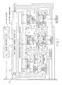
- an information processing system comprises a main memory 10, a control processor 11, an arithmetic processor 12, a system controller 13, and a diagnostic processor 14.
- a control processor 11 an arithmetic processor 12
- a system controller 13 a system controller 13
- a diagnostic processor 14 Each of the control and the arithmetic processors 11 and 12 is herein referred to as a standard processor.
- the diagnostic processor 14 comprises a diagnosing unit 15 which is connected to the main memory 10, the control processor 11, the arithmetic processor 12, and the system controller 13 through a diagnostic bus 16.
- the diagnosing unit 15 carries out a diagnosing operation on the main memory 10, the control processor 11, the arithmetic processor 12, and the system controller 13.
- a monitoring unit 18 monitors the diagnosing unit 15 and produces a state signal indicative of whether or not the diagnosing unit 15 is capable of carrying out the diagnosing operation. More specifically, when the monitoring unit 18 detects a failure in the diagnosing unit 15, the monitoring unit 18 produces the state signal indicating that the diagnosing unit 15 is not capable of carrying out the diagnosing operation.
- a diagnosis control unit 19 controls retry of the diagnosing operation in response to the state signal indicating that the diagnosing unit 15 is not capable of carrying out the diagnosing operation.
- the restart of the diagnosing operation is carried out as follows.
- the diagnostic control unit 19 saves data indispensable for a retry of the diagnosing unit 15 in a save area (not shown) as saved data at first. Subsequently, initialization is carried out for the diagnosing unit 15. Thereafter, restart of the diagnosing unit 15 is carried out. When the diagnosing unit 15 is thereby put into a state in which the retry can be made, the retry is actually carried out by using the saved data.
- the main memory 10 comprises a state indication area 20 connected to the monitoring unit 18 in the manner which will become clear as the description proceeds.
- the state indication area 20 memorizes the state signal as a state indication signal.
- the control processor 11 comprises a signal producing unit 21 which produces a communication request signal 22 and a read request signal 23.
- a communication control unit 24 of the control processor 11 receives the communication request signal 22 and controls delivery of the communication request signal 22 outwardly of the communication control unit 24.
- the communication control unit 24 of the control processor 11 serves as a delivery control unit.
- the delivery control unit controls delivery of the communication request signal 22 from the deliery control unit.
- the system controller 13 comprises an interprocessor communication controller 25 which is connected to the diagnosing unit 15 through a communication control unit 26 of the diagnostic processor 14 and is connected to the communication control unit 24 of the control processor 11 directly.
- the interprocessor communication controller 25 supplies the communication request signal 22 delivered from the communication control unit 24 of the control processor 11 to the diagnosing unit 15 as the activation signal 17.
- the interprocessor communication controller 25 serves as a communication request supply unit connected to the diagnosing unit 15 for supplying the communication request signal 22 delivered from the communication control unit 24 to the diagnosing unit 15 as the activation signal 17.
- a main memory request controller 27 supplies the read request signal 23 to the state indication area 20 to receive the state indication signal as a read-out state signal through the main memory access controller 28.
- the main memory request controller 27 acts as a read request supply unit which supplies the state indication area 20 with the read request signal 23 to receive the state indication signal as the read-out state signal.
- the control processor 11 further comprises a judging unit 29 which is connected to the communication control unit 24 of the control processor 11 directly and to the main memory request controller 27.
- the judging unit 29 judges the read-out state signal and produces first and second control signals when the read-out state signal indicates that the diagnosing unit 15 is and is not capable of carrying out the diagnosing operation, respectively.
- the judging unit 29 sends the first and the second control signals to the communication control unit 24 of the control processor 11 to allow and inhibit the delivery of the communication request signal 22 towards the interprocessor communication controller 25, respectively.
- the arithmetic processor 12 is similar in structure and in operation to the control processor 11.
- FIG. 2 With reference to Fig. 1 continued, description will be made as regards operation of the information processing system illustrated in Fig. 1. Although description will now be made only about an interprocessor communication operation from the control processor 11 to the diagnostic processor 14, another interprocessor communication operation from the arithmetic processor 12 to the diagnostic processor 14 is carried out in the manner similar to the interprocessor communication operation from the control processor 11 to the diagnostic processor 14.
- the signal producing unit 21 of the control processor 11 produces the communication request signal 22 and the read request signal 23 and that the communication control unit 24 of the control processor 11 receives the communication request signal 22 and controls delivery of the communication request signal 22 from the communication control unit 24.
- the main memory access controller 28 of the control processor 11 receives the read request signal 23 and sends the read request signal 23 to the main memory request controller 27.
- the first stage S1 proceeds to a second stage S2.
- the memory request controller 27 receives the read request signal 23 and supplies the state indication area 20 of the main memory 10 with the read request signal 23.
- the second stage S2 is succeeded by a third stage S3.
- the state indication area 20 of the main memory 10 receives the read request signal 23 and sends the state indication signal to the main memory request controller 27.
- the state indication area 20 has one byte length.
- the state indication signal has a hexadecimal value "00”
- the state indication signal indicates that the diagnosing unit 15 is capable of carrying out the diagnosing operation.
- the state indication signal has another hexadecimal value "FF”
- the state indication signal indicates that the diagnosing unit 15 is not capable of carrying out the diagnosing operation.
- the third stage S3 is followed by a fourth stage S4.
- the main memory request controller 27 receives the state indication signal as a read-out state signal and sends the read-out state signal to the judging unit 29 through the main memory access controller 28 of the control processor 11.
- the fourth stage S4 is succeeded by a fifth stage S5.
- the judging unit 29 judges the read-out state signal and produces the first and the second control signals when the read-out state signal indicates that the diagnosing unit 15 is and is not capable of carrying out the diagnosing operation, respectively. More specifically, the judging unit 29 produces the first and the second control signals when the read-out state sgnal has the hexadecimal values "00" and "FF", respectively.
- the judging unit 29 sends the first and the second control signals to the communication control unit 24 of the control processor 11 to allow and inhibit the delivery of the communication request signal 22 towards the interprocessor communication controller 25, respectively. That is, the communication control unit 24 delivers the communication request signal 22 to the interprocessor communication controller 25 when the communication control unit 24 receives the first control signal. When the communication control unit 24 receives the second control signal, the communication control unit 24 reserves the communication request signal 22 without delivering the communication request signal 22 from the communication control unit 24 to the interprocessor communication controller 25.
- the interprocessor communication controller 25 receives the communication request signal 22 and supplies the communication request signal 22 to the diagnosing unit 15 through the communication control unit 26 of the diagnosing processor 14 as the activation signal 17.
- a seventh stage S7 follows the sixth stage S6.
- the diagnosing unit 15 carries out the diagnosing operation in response to the activation signal 17. More specifically, the diagnosing unit 15 decodes the communication request signal 22 into a decoded signal which specifies a specific one of diagnosing programs. Thereafter, the diagnosing unit 15 carries out a specific diagnosing operation in accordance to the specific program. When the diagnosing unit 15 finishes the specific diagnosing operation, the diagnosing unit 15 produces a reply communication signal as an end report of the specific diagnosing operation. The diagnosing unit 15 sends the reply communication signal to the interprocessor communication controller 25 through the communication control unit 26 of the diagnostic processor 14.
- the interprocessor communication controller 25 receives the reply communication signal and sends the reply communication signal to the communication control unit 24 of the control processor 11.
- Fig. 3 with reference to Fig. 1 continued, description will be made as regards a writing operation of writing the state signal in the state indication area 20. It will be assumed that the monitoring unit 18 detects, at a first stage S′1 indicated by a cross, a failure in the diagnosing unit 15 and produces an abnormal state signal indicating that the diagnosing unit 15 is not capable of carrying out the diagnosing operation.
- the first stage S′1 is followed by second and third stages S′2 and S′3.
- the diagnosis control unit 19 controls retry of the diagnosing operation in response to the abnormal state signal.
- the diagnosis control unit 19 produces, in response to the abnormal state signal, a write request signal and delivers the write request signal together with the abnormal state signal to the main memory request controller 27 of the system controller 13 through a main memory access controller 30 of the diagnostic processor 14.
- the third stage S′3 is succeeded by a fourth stage S′4.
- the main memory request controller 27 supplies the write request signal and the abnormal state signal to the state indication area 20 of the main memory 10 to write the abnormal state signal in the state indication area 20 as the state indication signal. That is, the hexadecimal value "FF" is memorized in the state indication area 20 instead of the hexadecimal value "00" as depicted along a top line.
- the diagnosis control unit 19 of the diagnostic processor 14 finishes the retry of the diagnosing operation.
- the monitoring unit 18 of the diagnostic processor 14 produces a normal state signal indicating that the diagnosing unit 15 is capable of carrying out the diagnosing operation.
- the diagnosis control unit 19 produces first and second communication request signals to inform the control and the arithmetic processors 11 and 12 about an end of the retry, respectively.
- the diagnosis control unit 19 delivers not only the first communication signal directed to the control processor 11 but also the normal state signal to the interprocessor communication controller 25 of the system controller 13 through the communication control unit 26 of the diagnostic processor 14. Simultaneously, the diagnosis control unit 19 delivers the second communication request signal directed to the arithmetic processor 12.
- the interprocessor communication controller 25 of the system controller 13 supplies the first communication request signal and the normal state signal to the control processor 11. Simultaneously, the interprocessor communication controller 25 supplies the second communication request signal to the arithmetic processor 12.
- the control processor 11 receives the first communication request signal and the normal state signal and, thereby, knows the end of the retry of the diagnosing operation.
- the arithmetic processor 12 receives the second communication request signal, the arithmetic processor 12 knows the end of the diagnosing operation.
- the signal producing unit 21 of the control processor 11 receives the first communication request signal and the normal state signal through the communication control unit 24. In response to the first communication request signal, the signal producing unit 21 produces a write request signal and delivers the write request signal together with the normal state signal to the main memory request controller 27 of the system controller 13 through the main memory access controller 28 of the control processor 11.
- the seventh stage S′7 is succeeded by an eighth stage S′8.
- the main memory request controller 27 supplies the write request signal and the normal state signal to the state indication area 20 of the main memory 10 to write the normal state signal in the state indication area 20 as the state indication signal. That is, the hexadecimal value "00" is memorized in the state indication area 20 instead of the hexadecimal value "FF" as depicted along the top line.
- Fig. 4 with reference to Fig. 1 continued, description will proceed to another writing operation. It will be presumed that the signal producing unit 21 of the arithmetic processor 12 delivers a communication signal to the interprocessor communication controller 25 of the system controller 13 through the communication control unit 24 at a first stage S ⁇ 1. The communication signal is directed to the diagnostic processor 14.
- a timer unit 40 of the arithmetic processor 12 starts a measuring operation of a predetermined time interval in response to the communication signal.
- the timer unit 40 produces a time-out signal when the timer unit 40 can not receive a reply communication signal from the diagnostic processor 14 within the predetermined time duration.
- the monitoring unit 18 of the diagnostic processor 14 detects a failure in the diagnosing unit 15 immediately after the arithmetic processor 12 delivers the communication signal towards the system controller 13 at a third stage S ⁇ 3.
- the monitoring unit 18 thereby produces the abnormal state signal indicating that the diagnosing unit 15 is not capable of carrying out the diagnosing operation.
- the third stage S ⁇ 3 is followed by a fourth stage S ⁇ 4.
- the diagnosis control unit 19 of the diagnostic processor 14 controls retry of the diagnosing operation in response to the abnormal state signal.
- the communication control unit 26 of the diagnostic processor 14 receives the communication signal through the interprocessor communication controller 25 during the fourth stage S ⁇ 4, the communication control unit 26 makes the communication signal become invalid.
- the diagnosis control unit 19 delivers an invalidation instruction signal to the communication control unit 26 while the diagnosis control unit 19 controls the retry of the diagnosing operation.
- the communication control unit 26 renders the communication signal invalid.
- the diagnostic processor 14 Inasmuch as the communication signal is not supplied to the diagnosing unit 15, the diagnostic processor 14 never produces the reply communication signal. Therefore, the timer unit 40 of the arithmetic processor 12 can not receive the reply communication signal within the predetermined time duration and produces the time-out signal at the second stage S ⁇ 2.
- the second stage S ⁇ 2 is succeeded by a fifth stage S ⁇ 5.
- the signal producing unit 21 of the arithmetic processor 12 produces, in response to the time-out signal, a write request signal and the abnormal state signal and delivers the write request signal and the abnormal signal to the main memory request controller 27 of the system controller 13 through the main memory access controller 28 of the arithmetic processor 12.
- the main memory request controller 27 supplies the write request signal and the abnormal state signal to the state indication area 20 of the main memory 10 to write the abnormal state signal in the state indication area 20 as the indication signal. That is, the hexadecimal value "FF" is memorized in the state indication area 20 instead of the hexadecimal value "00" as depicted along a top line.
- the diagnosis control unit 19 of the diagnostic processor 14 finishes the retry of the diagnosing operation.
- the monitoring unit 18 of the diagnostic processor 14 produces a normal state signal indicating that the diagnosing unit 15 is capable of carrying out the diagnosing operation.
- the diagnosis control unit 19 produces first and second communication request signals to inform the control and the arithmetic processors 11 and 12 about an end of the retry, respectively.
- the diagnosis control unit 19 delivers not only the first communication signal directed to the control processor 11 but also the normal state signal to the interprocessor communication controller 25 of the system controller 13 through the communication control unit 26 of the diagnostic processor 14. Simultaneously, the diagnosis control unit 19 delivers the second communication request signal directed to the arithmetic processor 12.
- the interprocessor communication controller 25 of the system controller 13 supplies the first communication request signal and the normal state signal to the control processor 11. Simultaneously, the interprocessor communication controller 25 supplies the second communication request signal to the arithmetic processor 12.
- the control processor 11 receives the first communication request signal and the normal state signal and, thereby, knows the end of the retry of the diagnosing operation.
- the arithmetic processor 12 receives the second communication request signal, the arithmetic processor 12 knows the end of the diagnosing operation.
- the signal producing unit 21 of the control processor 11 receives the first communication request signal and the normal state signal through the communication control unit 24. In response to the first communication request signal, the signal producing unit 21 produces a write request signal and delivers the write request signal together with the normal state signal to the main memory request controller 27 of the system controller 13 through the main memory access controller 28 of the control processor 11.
- the ninth stage S ⁇ 9 is succeeded by a tenth stage S ⁇ 10.
- the main memory request controller 27 supplies the write request signal and the normal state signal to the state indication area 20 of the main memory 10 to write the normal state signal in the state indication area 20 as the state indication signal. That is, the hexadecimal value "00" is memorized in the state indication area 20 instead of the hexadecimal value "FF" as depicted along the top line.
Abstract
Description
- This invention relates to an information processing system comprising a main memory, at least one standard processor, a system controller, and a diagnostic processor. The standard processor is, for example, a control processor, an arithmetic processor, or the like.
- In an information processing system of the type described, the diagnostic processor comprises a diagnosing unit connected to the main memory, the standard processor, and the system controller. The diagnosing unit carries out a diagnosing operation on the main memory, the standard processor, and the system controller in response to an activation signal. Connected to the diagnosing unit, a monitoring unit detects a failure in the diagnosing unit, namely, monitors the diagnosing unit to produce a state signal indicative of whether or not the diagnosing unit can carry out the diagnosing operation. Connected to the diagnosing unit and the monitoring unit, a diagnosis control unit carries out a controlling operation of restart or retry of the diagnosing operation in response to the state signal when the state signal indicates that the diagnosing unit can not deal with the diagnosing operation. Such a controlling operation of retry of the diagnosing operation will later be described.
- It will be assumed that the information processing system comprises first and second standard processors. Each of the first and the second standard processors can put the diagnosing unit into a normal state of carrying out the diagnosing operation by sending, as the activation signal, a communication request signal to the diagnosing unit through the system controller. For example, the communication request signal is sent to inform the diagnosing unit that a failure occurs in the standard processor in question. Alternatively, the communication request signal is sent to make a request for log-out which is known in the art. It will also be assumed that the diagnosing unit is put in the normal state by a first communication request signal sent by the first standard processor and that the monitoring unit finds a failure to put the diagnosis control unit into the controlling operation of retry of the diagnosing operation. In this event, the diagnosing unit is temporarily put in an interrupted state of interrupting the diagnosing operation.
- It will furthermore be assumed that the second standard processor sends, as the activation signal, a second communication request signal to the diagnosing unit through the system controller while the diagnosing unit is kept in the interrupted state.
- In a conventional information processing system, the system controller reserves, in such a case, the second communication request without delivering the second communication request signal from the system controller to the diagnostic processor until the diagnosing operation is fully retried. In many cases, the second standard processor can not receive a reply communication signal from the diagnosing unit through the system controller within a predetermined time duration after the second communication request signal is sent to the system controller. Therefore, the second standard processor is subjected to a time-out error. This puts the information processing system into system down.
- It is therefore an object of this invention to provide an information processing system which is not subjected to system down even when a diagnostic processor carries out retry of a diagnosing operation thereof.
- It is another object of this invention to provide an information processing system of the type described, which is capable of effectively making use of a time-out error occurred in a standard processor when a diagnostic processor carries out retry of a diagnosing operation thereof.
- On describing the gist of this invention, it is possible to understand that an information processing system comprises a main memory, a standard processor, a system controller, and a diagnostic processor comprising: diagnosing means connected to the main memory, the standard processor, and the system controller for carrying out a diagnosing operation on the main memory, the standard processor, and the system controller in response to an activation signal; monitoring means connected to the diagnosing means for monitoring the diagnosing means to produce a state signal indicative of whether or not the diagnosing means is capable of carrying out the diagnosing operation; and diagnosis control means connected to the diagnosing means and the monitoring means for controlling retry of the diagnosing operation in response to the state signal indicating that the diagnosing means is not capable of carrying out the diagnosing operation.
- According to this invention, the main memory comprises, in the above-understood information processing system, a state indication area connected to the monitoring means for memorizing the state signal as a state indication signal. The standard processor comprises: signal producing means for producing a communication request signal and a read request signal; and delivery control means connected to the signal producing means for controlling deliery of the communication request signal from the delivery control means. The system controller comprises: communication request supply means connected to the diagnosing means and the delivery control means for supplying the communication request signal delivered from the delivery control means to the diagnosing means as the activation signal; and read request supply means connected to the state indication area and the signal producing means for supplying the state indication area with the read request signal to receive the state indication signal as a read-out state signal. The standard processor further comprises judging means connected to the delivery control means and the read request supply means for judging the read-out state signal to produce first and second control signals when the diagnosing means is and is not capable of carrying out the diagnosing operation, respectively. The judging means sends the first and the second control signals to the delivery control means to allow and inhibit the delivery, respectively.
-
- Fig. 1 is a block diagram of an information processing system according to an embodiment of this invention;
- Fig. 2 is a time chart for use in describing operation of the information processing system illustrated in Fig. 1;
- Fig. 3 is another time chart for use in describing another operation of the information processing system illustrated in Fig. 1; and
- Fig. 4 is still another time chart for use in describing still another operation of the information processing system illustrated in Fig. 1.
- Referring to Fig. 1, an information processing system according to a preferred embodiment of this invention comprises a
main memory 10, acontrol processor 11, anarithmetic processor 12, asystem controller 13, and adiagnostic processor 14. Each of the control and thearithmetic processors - The
diagnostic processor 14 comprises adiagnosing unit 15 which is connected to themain memory 10, thecontrol processor 11, thearithmetic processor 12, and thesystem controller 13 through adiagnostic bus 16. In response to anactivation signal 17 which will later be described, thediagnosing unit 15 carries out a diagnosing operation on themain memory 10, thecontrol processor 11, thearithmetic processor 12, and thesystem controller 13. Connected to thediagnosing unit 15, amonitoring unit 18 monitors thediagnosing unit 15 and produces a state signal indicative of whether or not thediagnosing unit 15 is capable of carrying out the diagnosing operation. More specifically, when themonitoring unit 18 detects a failure in thediagnosing unit 15, themonitoring unit 18 produces the state signal indicating that thediagnosing unit 15 is not capable of carrying out the diagnosing operation. Connected to thediagnosing unit 15 and themonitoring unit 18, adiagnosis control unit 19 controls retry of the diagnosing operation in response to the state signal indicating that thediagnosing unit 15 is not capable of carrying out the diagnosing operation. - More specifically, the restart of the diagnosing operation is carried out as follows. The
diagnostic control unit 19 saves data indispensable for a retry of thediagnosing unit 15 in a save area (not shown) as saved data at first. Subsequently, initialization is carried out for thediagnosing unit 15. Thereafter, restart of thediagnosing unit 15 is carried out. When thediagnosing unit 15 is thereby put into a state in which the retry can be made, the retry is actually carried out by using the saved data. - The
main memory 10 comprises astate indication area 20 connected to themonitoring unit 18 in the manner which will become clear as the description proceeds. Thestate indication area 20 memorizes the state signal as a state indication signal. - The
control processor 11 comprises asignal producing unit 21 which produces acommunication request signal 22 and aread request signal 23. Connected to thesignal producing unit 21, acommunication control unit 24 of thecontrol processor 11 receives thecommunication request signal 22 and controls delivery of thecommunication request signal 22 outwardly of thecommunication control unit 24. Thus, thecommunication control unit 24 of thecontrol processor 11 serves as a delivery control unit. Connected to thesignal producing unit 21, the delivery control unit controls delivery of thecommunication request signal 22 from the deliery control unit. - The
system controller 13 comprises aninterprocessor communication controller 25 which is connected to thediagnosing unit 15 through acommunication control unit 26 of thediagnostic processor 14 and is connected to thecommunication control unit 24 of thecontrol processor 11 directly. Theinterprocessor communication controller 25 supplies thecommunication request signal 22 delivered from thecommunication control unit 24 of thecontrol processor 11 to thediagnosing unit 15 as theactivation signal 17. Thus, theinterprocessor communication controller 25 serves as a communication request supply unit connected to thediagnosing unit 15 for supplying thecommunication request signal 22 delivered from thecommunication control unit 24 to thediagnosing unit 15 as theactivation signal 17. - Connected to the
state indication area 20 directly and to thesignal producing unit 21 through a mainmemory access controller 28 of thecontrol processor 11, a mainmemory request controller 27 supplies theread request signal 23 to thestate indication area 20 to receive the state indication signal as a read-out state signal through the mainmemory access controller 28. Thus, the mainmemory request controller 27 acts as a read request supply unit which supplies thestate indication area 20 with theread request signal 23 to receive the state indication signal as the read-out state signal. - The
control processor 11 further comprises ajudging unit 29 which is connected to thecommunication control unit 24 of thecontrol processor 11 directly and to the mainmemory request controller 27. Thejudging unit 29 judges the read-out state signal and produces first and second control signals when the read-out state signal indicates that thediagnosing unit 15 is and is not capable of carrying out the diagnosing operation, respectively. Thejudging unit 29 sends the first and the second control signals to thecommunication control unit 24 of thecontrol processor 11 to allow and inhibit the delivery of thecommunication request signal 22 towards theinterprocessor communication controller 25, respectively. - The
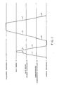
arithmetic processor 12 is similar in structure and in operation to thecontrol processor 11. - Turning to Fig. 2 with reference to Fig. 1 continued, description will be made as regards operation of the information processing system illustrated in Fig. 1. Although description will now be made only about an interprocessor communication operation from the
control processor 11 to thediagnostic processor 14, another interprocessor communication operation from thearithmetic processor 12 to thediagnostic processor 14 is carried out in the manner similar to the interprocessor communication operation from thecontrol processor 11 to thediagnostic processor 14. - It will be assumed that the
signal producing unit 21 of thecontrol processor 11 produces thecommunication request signal 22 and theread request signal 23 and that thecommunication control unit 24 of thecontrol processor 11 receives thecommunication request signal 22 and controls delivery of thecommunication request signal 22 from thecommunication control unit 24. - At a first stage S1, the main
memory access controller 28 of thecontrol processor 11 receives theread request signal 23 and sends theread request signal 23 to the mainmemory request controller 27. The first stage S1 proceeds to a second stage S2. - At the second stage S2, the
memory request controller 27 receives the readrequest signal 23 and supplies thestate indication area 20 of themain memory 10 with the readrequest signal 23. The second stage S2 is succeeded by a third stage S3. - At the third stage S3, the
state indication area 20 of themain memory 10 receives the readrequest signal 23 and sends the state indication signal to the mainmemory request controller 27. For example, thestate indication area 20 has one byte length. When the state indication signal has a hexadecimal value "00", the state indication signal indicates that the diagnosingunit 15 is capable of carrying out the diagnosing operation. When the state indication signal has another hexadecimal value "FF", the state indication signal indicates that the diagnosingunit 15 is not capable of carrying out the diagnosing operation. The third stage S3 is followed by a fourth stage S4. - At the fourth stage S4, the main
memory request controller 27 receives the state indication signal as a read-out state signal and sends the read-out state signal to the judgingunit 29 through the mainmemory access controller 28 of thecontrol processor 11. The fourth stage S4 is succeeded by a fifth stage S5. - At the fifth stage S5, the judging
unit 29 judges the read-out state signal and produces the first and the second control signals when the read-out state signal indicates that the diagnosingunit 15 is and is not capable of carrying out the diagnosing operation, respectively. More specifically, the judgingunit 29 produces the first and the second control signals when the read-out state sgnal has the hexadecimal values "00" and "FF", respectively. - The judging
unit 29 sends the first and the second control signals to thecommunication control unit 24 of thecontrol processor 11 to allow and inhibit the delivery of thecommunication request signal 22 towards theinterprocessor communication controller 25, respectively. That is, thecommunication control unit 24 delivers thecommunication request signal 22 to theinterprocessor communication controller 25 when thecommunication control unit 24 receives the first control signal. When thecommunication control unit 24 receives the second control signal, thecommunication control unit 24 reserves thecommunication request signal 22 without delivering thecommunication request signal 22 from thecommunication control unit 24 to theinterprocessor communication controller 25. - At a sixth stage S6 which follows the fifth stage S5, the
interprocessor communication controller 25 receives thecommunication request signal 22 and supplies thecommunication request signal 22 to the diagnosingunit 15 through thecommunication control unit 26 of the diagnosingprocessor 14 as theactivation signal 17. - A seventh stage S7 follows the sixth stage S6. At the seventh stage S7, the diagnosing
unit 15 carries out the diagnosing operation in response to theactivation signal 17. More specifically, the diagnosingunit 15 decodes thecommunication request signal 22 into a decoded signal which specifies a specific one of diagnosing programs. Thereafter, the diagnosingunit 15 carries out a specific diagnosing operation in accordance to the specific program. When the diagnosingunit 15 finishes the specific diagnosing operation, the diagnosingunit 15 produces a reply communication signal as an end report of the specific diagnosing operation. The diagnosingunit 15 sends the reply communication signal to theinterprocessor communication controller 25 through thecommunication control unit 26 of thediagnostic processor 14. - At an eighth stage S8 which succeeds the seventh stage S7, the
interprocessor communication controller 25 receives the reply communication signal and sends the reply communication signal to thecommunication control unit 24 of thecontrol processor 11. - Turning to Fig. 3 with reference to Fig. 1 continued, description will be made as regards a writing operation of writing the state signal in the
state indication area 20. It will be assumed that themonitoring unit 18 detects, at a first stage S′1 indicated by a cross, a failure in the diagnosingunit 15 and produces an abnormal state signal indicating that the diagnosingunit 15 is not capable of carrying out the diagnosing operation. The first stage S′1 is followed by second and third stages S′2 and S′3. - At the second stage S′2, the
diagnosis control unit 19 controls retry of the diagnosing operation in response to the abnormal state signal. - At the third stage S′3, the
diagnosis control unit 19 produces, in response to the abnormal state signal, a write request signal and delivers the write request signal together with the abnormal state signal to the mainmemory request controller 27 of thesystem controller 13 through a mainmemory access controller 30 of thediagnostic processor 14. The third stage S′3 is succeeded by a fourth stage S′4. - At the fourth stage S′4, the main
memory request controller 27 supplies the write request signal and the abnormal state signal to thestate indication area 20 of themain memory 10 to write the abnormal state signal in thestate indication area 20 as the state indication signal. That is, the hexadecimal value "FF" is memorized in thestate indication area 20 instead of the hexadecimal value "00" as depicted along a top line. - At a fifth stage S′5 which succeeds the second stage S′2, the
diagnosis control unit 19 of thediagnostic processor 14 finishes the retry of the diagnosing operation. In this event, themonitoring unit 18 of thediagnostic processor 14 produces a normal state signal indicating that the diagnosingunit 15 is capable of carrying out the diagnosing operation. When thediagnosis control unit 19 completes the retry of the diagnosing operation, thediagnosis control unit 19 produces first and second communication request signals to inform the control and thearithmetic processors diagnosis control unit 19 delivers not only the first communication signal directed to thecontrol processor 11 but also the normal state signal to theinterprocessor communication controller 25 of thesystem controller 13 through thecommunication control unit 26 of thediagnostic processor 14. Simultaneously, thediagnosis control unit 19 delivers the second communication request signal directed to thearithmetic processor 12. - At a sixth stage S′6 which follows the fifth stage S′5, the
interprocessor communication controller 25 of thesystem controller 13 supplies the first communication request signal and the normal state signal to thecontrol processor 11. Simultaneously, theinterprocessor communication controller 25 supplies the second communication request signal to thearithmetic processor 12. Thecontrol processor 11 receives the first communication request signal and the normal state signal and, thereby, knows the end of the retry of the diagnosing operation. When thearithmetic processor 12 receives the second communication request signal, thearithmetic processor 12 knows the end of the diagnosing operation. - At a seventh stage S′7 which follows the sixth stage S′6, the
signal producing unit 21 of thecontrol processor 11 receives the first communication request signal and the normal state signal through thecommunication control unit 24. In response to the first communication request signal, thesignal producing unit 21 produces a write request signal and delivers the write request signal together with the normal state signal to the mainmemory request controller 27 of thesystem controller 13 through the mainmemory access controller 28 of thecontrol processor 11. The seventh stage S′7 is succeeded by an eighth stage S′8. - At the eighth stage S′8, the main
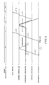
memory request controller 27 supplies the write request signal and the normal state signal to thestate indication area 20 of themain memory 10 to write the normal state signal in thestate indication area 20 as the state indication signal. That is, the hexadecimal value "00" is memorized in thestate indication area 20 instead of the hexadecimal value "FF" as depicted along the top line. - Turning to Fig. 4 with reference to Fig. 1 continued, description will proceed to another writing operation. It will be presumed that the
signal producing unit 21 of thearithmetic processor 12 delivers a communication signal to theinterprocessor communication controller 25 of thesystem controller 13 through thecommunication control unit 24 at a first stage S˝1. The communication signal is directed to thediagnostic processor 14. - At a second stage S˝2, a
timer unit 40 of thearithmetic processor 12 starts a measuring operation of a predetermined time interval in response to the communication signal. Thetimer unit 40 produces a time-out signal when thetimer unit 40 can not receive a reply communication signal from thediagnostic processor 14 within the predetermined time duration. - It will also be presumed that the
monitoring unit 18 of thediagnostic processor 14 detects a failure in the diagnosingunit 15 immediately after thearithmetic processor 12 delivers the communication signal towards thesystem controller 13 at a third stage S˝3. Themonitoring unit 18 thereby produces the abnormal state signal indicating that the diagnosingunit 15 is not capable of carrying out the diagnosing operation. The third stage S˝3 is followed by a fourth stage S˝4. - At the fourth stage S˝4, the
diagnosis control unit 19 of thediagnostic processor 14 controls retry of the diagnosing operation in response to the abnormal state signal. When thecommunication control unit 26 of thediagnostic processor 14 receives the communication signal through theinterprocessor communication controller 25 during the fourth stage S˝4, thecommunication control unit 26 makes the communication signal become invalid. More specifically, thediagnosis control unit 19 delivers an invalidation instruction signal to thecommunication control unit 26 while thediagnosis control unit 19 controls the retry of the diagnosing operation. In accordance with the invalidation instruction signal, thecommunication control unit 26 renders the communication signal invalid. - Attention will be directed to the second stage S˝2. Inasmuch as the communication signal is not supplied to the diagnosing
unit 15, thediagnostic processor 14 never produces the reply communication signal. Therefore, thetimer unit 40 of thearithmetic processor 12 can not receive the reply communication signal within the predetermined time duration and produces the time-out signal at the second stage S˝2. The second stage S˝2 is succeeded by a fifth stage S˝5. - At the fifth stage S˝5, the
signal producing unit 21 of thearithmetic processor 12 produces, in response to the time-out signal, a write request signal and the abnormal state signal and delivers the write request signal and the abnormal signal to the mainmemory request controller 27 of thesystem controller 13 through the mainmemory access controller 28 of thearithmetic processor 12. - At a sixth stage S˝6 which follows the fifth stage S˝5, the main
memory request controller 27 supplies the write request signal and the abnormal state signal to thestate indication area 20 of themain memory 10 to write the abnormal state signal in thestate indication area 20 as the indication signal. That is, the hexadecimal value "FF" is memorized in thestate indication area 20 instead of the hexadecimal value "00" as depicted along a top line. - At a seventh stage S˝7 which succeeds the second stage S˝5, the
diagnosis control unit 19 of thediagnostic processor 14 finishes the retry of the diagnosing operation. In this event, themonitoring unit 18 of thediagnostic processor 14 produces a normal state signal indicating that the diagnosingunit 15 is capable of carrying out the diagnosing operation. When thediagnosis control unit 19 completes the retry of the diagnosing operation, thediagnosis control unit 19 produces first and second communication request signals to inform the control and thearithmetic processors diagnosis control unit 19 delivers not only the first communication signal directed to thecontrol processor 11 but also the normal state signal to theinterprocessor communication controller 25 of thesystem controller 13 through thecommunication control unit 26 of thediagnostic processor 14. Simultaneously, thediagnosis control unit 19 delivers the second communication request signal directed to thearithmetic processor 12. - At an eighth stage S˝8 which follows the seventh stage S˝7, the
interprocessor communication controller 25 of thesystem controller 13 supplies the first communication request signal and the normal state signal to thecontrol processor 11. Simultaneously, theinterprocessor communication controller 25 supplies the second communication request signal to thearithmetic processor 12. Thecontrol processor 11 receives the first communication request signal and the normal state signal and, thereby, knows the end of the retry of the diagnosing operation. When thearithmetic processor 12 receives the second communication request signal, thearithmetic processor 12 knows the end of the diagnosing operation. - At a ninth stage S˝9 which follows the eighth stage S˝8 for the
control processor 11, thesignal producing unit 21 of thecontrol processor 11 receives the first communication request signal and the normal state signal through thecommunication control unit 24. In response to the first communication request signal, thesignal producing unit 21 produces a write request signal and delivers the write request signal together with the normal state signal to the mainmemory request controller 27 of thesystem controller 13 through the mainmemory access controller 28 of thecontrol processor 11. The ninth stage S˝9 is succeeded by a tenth stage S˝10. - At the tenth stage S˝10, the main
memory request controller 27 supplies the write request signal and the normal state signal to thestate indication area 20 of themain memory 10 to write the normal state signal in thestate indication area 20 as the state indication signal. That is, the hexadecimal value "00" is memorized in thestate indication area 20 instead of the hexadecimal value "FF" as depicted along the top line.
Claims (1)
said main memory comprising a state indication area operatively connected to said monitoring means for memorizing said state signal as a state indication signal;
said standard processor comprising:
signal producing means for producing a communication request signal and a read request signal; and
delivery control means connected to said signal producing means for controlling delivery of said communication request signal from said delivery control means;
said system controller comprising:
communication request supply means connected to said diagnosing means and said delivery control means for supplying the communication request signal delivered from said delivery control means to said diagnosing means as said activation signal; and
read request supply means connected to said state indication area and said signal producing means for supplying said state indication area with said read request signal to receive said state indication signal as a read-out state signal;
said standard processor further comprising judging means connected to said delivery control means and said read request supply means for judging said read-out state signal to produce first and second control signals when said diagnosing means is and is not capable of carrying out said diagnosing operation, respectively, said judging means sending said first and said second control signals to said delivery control means to allow and inhibit said delivery, respectively.
Applications Claiming Priority (2)
| Application Number | Priority Date | Filing Date | Title |
|---|---|---|---|
| JP1154727A JPH07120292B2 (en) | 1989-06-19 | 1989-06-19 | Information processing system |
| JP154727/89 | 1989-06-19 |
Publications (3)
| Publication Number | Publication Date |
|---|---|
| EP0404056A2 true EP0404056A2 (en) | 1990-12-27 |
| EP0404056A3 EP0404056A3 (en) | 1991-12-18 |
| EP0404056B1 EP0404056B1 (en) | 1994-10-19 |
Family
ID=15590631
Family Applications (1)
| Application Number | Title | Priority Date | Filing Date |
|---|---|---|---|
| EP90111552A Expired - Lifetime EP0404056B1 (en) | 1989-06-19 | 1990-06-19 | Information processing system comprising a main memory having an area for memorizing a state signal related to a diagnosing operation |
Country Status (6)
| Country | Link |
|---|---|
| US (1) | US5249299A (en) |
| EP (1) | EP0404056B1 (en) |
| JP (1) | JPH07120292B2 (en) |
| AU (1) | AU626431B2 (en) |
| CA (1) | CA2019150C (en) |
| DE (1) | DE69013406T2 (en) |
Families Citing this family (8)
| Publication number | Priority date | Publication date | Assignee | Title |
|---|---|---|---|---|
| US5825989A (en) * | 1992-06-12 | 1998-10-20 | Xerox Corporation | System for diagnosing a source of malfunction resulting from the execution of a print job in a network printing system |
| EP0590175B1 (en) * | 1992-09-28 | 1996-07-24 | Siemens Aktiengesellschaft | System for controlling a process |
| US5363501A (en) * | 1992-12-22 | 1994-11-08 | Sony Electronics, Inc. | Method for computer system development verification and testing using portable diagnostic/testing programs |
| GB2290891B (en) * | 1994-06-29 | 1999-02-17 | Mitsubishi Electric Corp | Multiprocessor system |
| JP6119518B2 (en) | 2013-02-12 | 2017-04-26 | ソニー株式会社 | Sensor device, input device and electronic apparatus |
| JP6288073B2 (en) | 2013-03-18 | 2018-03-07 | ソニー株式会社 | Sensor device, input device and electronic device |
| JP6142745B2 (en) | 2013-09-10 | 2017-06-07 | ソニー株式会社 | Sensor device, input device and electronic apparatus |
| JP2015190859A (en) | 2014-03-28 | 2015-11-02 | ソニー株式会社 | Sensor device, input device, and electronic apparatus |
Citations (2)
| Publication number | Priority date | Publication date | Assignee | Title |
|---|---|---|---|---|
| US3876987A (en) * | 1972-04-26 | 1975-04-08 | Robin Edward Dalton | Multiprocessor computer systems |
| US3916177A (en) * | 1973-12-10 | 1975-10-28 | Honeywell Inf Systems | Remote entry diagnostic and verification procedure apparatus for a data processing unit |
Family Cites Families (4)
| Publication number | Priority date | Publication date | Assignee | Title |
|---|---|---|---|---|
| IN155448B (en) * | 1980-03-19 | 1985-02-02 | Int Computers Ltd | |
| JPS6053339B2 (en) * | 1980-10-09 | 1985-11-25 | 日本電気株式会社 | Logical unit error recovery method |
| US4703446A (en) * | 1984-07-03 | 1987-10-27 | Nec Corporation | Data processing unit diagnosis control apparatus |
| EP0256267B1 (en) * | 1986-08-12 | 1994-03-02 | Hitachi, Ltd. | Microprocessor for retrying data transfer |
-
1989
- 1989-06-19 JP JP1154727A patent/JPH07120292B2/en not_active Expired - Lifetime
-
1990
- 1990-06-18 CA CA002019150A patent/CA2019150C/en not_active Expired - Fee Related
- 1990-06-19 AU AU57634/90A patent/AU626431B2/en not_active Ceased
- 1990-06-19 US US07/539,822 patent/US5249299A/en not_active Expired - Fee Related
- 1990-06-19 DE DE69013406T patent/DE69013406T2/en not_active Expired - Fee Related
- 1990-06-19 EP EP90111552A patent/EP0404056B1/en not_active Expired - Lifetime
Patent Citations (2)
| Publication number | Priority date | Publication date | Assignee | Title |
|---|---|---|---|---|
| US3876987A (en) * | 1972-04-26 | 1975-04-08 | Robin Edward Dalton | Multiprocessor computer systems |
| US3916177A (en) * | 1973-12-10 | 1975-10-28 | Honeywell Inf Systems | Remote entry diagnostic and verification procedure apparatus for a data processing unit |
Non-Patent Citations (2)
| Title |
|---|
| CONTROL ENGINEERING vol. 30, no. 11, October 1983, ST. PONTIAC, USA pages 76 - 78; T. BALPH: 'Multipe Processor Control Systems Provide Higher Performance and Improved Diagnostics' * |
| IBM TECHNICAL DISCLOSURE BULLETIN vol. 30, no. 1, June 1987, ARMONK, USA pages 300 - 303; 'Background Diagnostics in a Diskette Machine' * |
Also Published As
| Publication number | Publication date |
|---|---|
| JPH07120292B2 (en) | 1995-12-20 |
| US5249299A (en) | 1993-09-28 |
| CA2019150C (en) | 1994-01-11 |
| EP0404056A3 (en) | 1991-12-18 |
| AU626431B2 (en) | 1992-07-30 |
| DE69013406D1 (en) | 1994-11-24 |
| CA2019150A1 (en) | 1990-12-19 |
| DE69013406T2 (en) | 1995-05-04 |
| AU5763490A (en) | 1990-12-20 |
| JPH0320832A (en) | 1991-01-29 |
| EP0404056B1 (en) | 1994-10-19 |
Similar Documents
| Publication | Publication Date | Title |
|---|---|---|
| US4729124A (en) | Diagnostic system | |
| EP0486304B1 (en) | Initialising computer systems | |
| US6874103B2 (en) | Adapter-based recovery server option | |
| EP0404056B1 (en) | Information processing system comprising a main memory having an area for memorizing a state signal related to a diagnosing operation | |
| US4999838A (en) | Failure recovery informing arrangement with simplified hardware in a data processing system | |
| EP0477385B1 (en) | Method of resetting adapter module at failing time and computer system executing said method | |
| JPH08178976A (en) | Power breakage detector | |
| JPH08329006A (en) | Fault information system | |
| JP2998804B2 (en) | Multi-microprocessor system | |
| JPH1185569A (en) | Processor | |
| JPS6052459B2 (en) | Microprogram control method | |
| JPH02281343A (en) | Cpu operation monitor system | |
| JPH08263320A (en) | System operation management method and operation management device | |
| JP2595697B2 (en) | Message processing system | |
| JP2679575B2 (en) | I / O channel fault handling system | |
| JPH02224170A (en) | Multiprocessor control device | |
| JPH0353345A (en) | Controller with automatic self-diagnostic function | |
| JPS59119451A (en) | Diagnosing system of electronic computer system | |
| JPH09198334A (en) | Fault managing method for data transmission system | |
| JP3472051B2 (en) | Transmission device and internal control method | |
| JPS6034132B2 (en) | programmable controller | |
| JPH10283029A (en) | Plant control controller | |
| JPS6367651A (en) | Data processor with monitoring program supervisory function | |
| KR19980014207A (en) | Apparatus and method for processing data protocol of a multiprocessor system | |
| JPH0353663B2 (en) |
Legal Events
| Date | Code | Title | Description |
|---|---|---|---|
| PUAI | Public reference made under article 153(3) epc to a published international application that has entered the european phase |
Free format text: ORIGINAL CODE: 0009012 |
|
| 17P | Request for examination filed |
Effective date: 19900713 |
|
| AK | Designated contracting states |
Kind code of ref document: A2 Designated state(s): BE DE FR GB NL SE |
|
| PUAL | Search report despatched |
Free format text: ORIGINAL CODE: 0009013 |
|
| AK | Designated contracting states |
Kind code of ref document: A3 Designated state(s): BE DE FR GB NL SE |
|
| 17Q | First examination report despatched |
Effective date: 19930916 |
|
| GRAA | (expected) grant |
Free format text: ORIGINAL CODE: 0009210 |
|
| AK | Designated contracting states |
Kind code of ref document: B1 Designated state(s): BE DE FR GB NL SE |
|
| PG25 | Lapsed in a contracting state [announced via postgrant information from national office to epo] |
Ref country code: FR Effective date: 19941019 Ref country code: BE Effective date: 19941019 |
|
| REF | Corresponds to: |
Ref document number: 69013406 Country of ref document: DE Date of ref document: 19941124 |
|
| PG25 | Lapsed in a contracting state [announced via postgrant information from national office to epo] |
Ref country code: SE Effective date: 19950119 |
|
| EN | Fr: translation not filed | ||
| RAP2 | Party data changed (patent owner data changed or rights of a patent transferred) |
Owner name: NEC CORPORATION |
|
| K2C3 | Correction of patent specification (complete document) published |
Effective date: 19941019 |
|
| PLBE | No opposition filed within time limit |
Free format text: ORIGINAL CODE: 0009261 |
|
| STAA | Information on the status of an ep patent application or granted ep patent |
Free format text: STATUS: NO OPPOSITION FILED WITHIN TIME LIMIT |
|
| K2C2 | Correction of patent specification (partial reprint) published |
Effective date: 19941019 |
|
| 26N | No opposition filed | ||
| PGFP | Annual fee paid to national office [announced via postgrant information from national office to epo] |
Ref country code: GB Payment date: 19990616 Year of fee payment: 10 |
|
| PGFP | Annual fee paid to national office [announced via postgrant information from national office to epo] |
Ref country code: DE Payment date: 19990618 Year of fee payment: 10 |
|
| PGFP | Annual fee paid to national office [announced via postgrant information from national office to epo] |
Ref country code: NL Payment date: 19990628 Year of fee payment: 10 |
|
| PG25 | Lapsed in a contracting state [announced via postgrant information from national office to epo] |
Ref country code: GB Free format text: LAPSE BECAUSE OF NON-PAYMENT OF DUE FEES Effective date: 20000619 |
|
| PG25 | Lapsed in a contracting state [announced via postgrant information from national office to epo] |
Ref country code: NL Free format text: LAPSE BECAUSE OF NON-PAYMENT OF DUE FEES Effective date: 20010101 |
|
| GBPC | Gb: european patent ceased through non-payment of renewal fee |
Effective date: 20000619 |
|
| NLV4 | Nl: lapsed or anulled due to non-payment of the annual fee |
Effective date: 20010101 |
|
| PG25 | Lapsed in a contracting state [announced via postgrant information from national office to epo] |
Ref country code: DE Free format text: LAPSE BECAUSE OF NON-PAYMENT OF DUE FEES Effective date: 20010403 |