EP0404035B1 - Powered screwdriver - Google Patents
Powered screwdriver Download PDFInfo
- Publication number
- EP0404035B1 EP0404035B1 EP19900111491 EP90111491A EP0404035B1 EP 0404035 B1 EP0404035 B1 EP 0404035B1 EP 19900111491 EP19900111491 EP 19900111491 EP 90111491 A EP90111491 A EP 90111491A EP 0404035 B1 EP0404035 B1 EP 0404035B1
- Authority
- EP
- European Patent Office
- Prior art keywords
- coupling
- power wrench
- gear
- output shaft
- wrench according
- Prior art date
- Legal status (The legal status is an assumption and is not a legal conclusion. Google has not performed a legal analysis and makes no representation as to the accuracy of the status listed.)
- Expired - Lifetime
Links
Images


Classifications
-
- B—PERFORMING OPERATIONS; TRANSPORTING
- B25—HAND TOOLS; PORTABLE POWER-DRIVEN TOOLS; MANIPULATORS
- B25B—TOOLS OR BENCH DEVICES NOT OTHERWISE PROVIDED FOR, FOR FASTENING, CONNECTING, DISENGAGING OR HOLDING
- B25B21/00—Portable power-driven screw or nut setting or loosening tools; Attachments for drilling apparatus serving the same purpose
- B25B21/008—Portable power-driven screw or nut setting or loosening tools; Attachments for drilling apparatus serving the same purpose with automatic change-over from high speed-low torque mode to low speed-high torque mode
Definitions
- the invention relates to a power wrench according to the preamble of claim 1.
- Motor-driven power screwdrivers are known in which the speed and the torque associated with the speed can be switched over manually or automatically as a function of the screwing torque.
- the supply pressure is measured and the screwdriver is switched to a higher torque when the supply pressure exceeds a certain limit.
- the tightening torque is automatically switched depending on the current consumed.
- the required reduction of the high speed of the motor output shaft takes place via several conventional gear stages with toothed wheels which are offset laterally with respect to one another.
- the gear stages have a relatively large space requirement and a relatively high weight.
- a power wrench is known (DE 37 20 633 A1), which has three planetary gears arranged in series between an input shaft and an output shaft.
- the ring gears of the input and output-side planetary gears are both axially displaceable and rotatably mounted in the housing of the power wrench, the ring gear of the input-side planetary gear being fixed by a clutch in a first position on the planet gear carrier and in a second position on the housing.
- the clutch is in the first position, so that the ring gear of the input-side planetary gear is frictionally fixed on the planet carrier and rotates together with it at the same relatively high speed.
- the clutch When a certain torque is exceeded, the clutch is moved into the second position by a spring-loaded cam mechanism. As a result, the ring gear of the input-side planetary gear is blocked against rotation in the housing and the clamping force between the ring gear and the planet carrier is released. The planet carrier consequently rotates at a relatively low speed. Furthermore, the power wrench also has a second clutch designed as a slip clutch, which interrupts the torque transmission when a maximum torque is exceeded.
- the switching mechanism for switching the gear ratio of the input-side gear stage is relatively complex.
- the ring gears of the planetary gears are both rotatably and axially displaceably mounted in the housing and must be shifted against each other by a complicated mechanism in such a way that the ring gear of the input-side planetary gear can be fixed either on the housing or on the planet carrier.
- the clutch which fixes the ring gear of the input-side planetary gear on the planet carrier or on the housing, forms a structural unit with the planetary gear, so that the structure of the switching mechanism is relatively complicated.
- the axially movable parts have to be manufactured with low manufacturing tolerances. There is a risk that the axially displaceable parts jam in their guides and block the switching mechanism.
- a power wrench with a torque-dependent manual transmission the type specified in the preamble of claim 1 is known from US-A-3 430 521.
- the known power screwdriver has a first gear stage containing a planetary gear and a second gear stage arranged in series with the first gear stage.
- the gear stages form two parallel drive branches that run continuously.
- the first drive branch can be coupled to the output shaft of the power wrench via a first clutch and the second drive branch can be coupled to the output shaft via a second clutch.
- the couplings have a coupling body which consists of two mutually coupled, counter-rotating coupling parts which are mounted on the output shaft so as to be displaceable in the axial direction and can be brought into engagement with corresponding coupling parts of the two coupling branches.
- the coupling surfaces of the coupling parts are tooth-shaped.
- the inner clutch part When a certain limit torque is exceeded, the inner clutch part is pushed back on the output shaft, so that one clutch is disengaged.
- the outer clutch part which is coupled to the inner clutch part, is advanced so that the other clutch is engaged and the output shaft rotates at a lower speed and greater torque.
- a disadvantage of the known power screwdriver is that a relatively complex mechanism is required in order to be able to switch the power screwdriver back from the gear position with lower speed and greater torque back to the gear position with higher speed and smaller torque.
- the invention has for its object to provide a power wrench of the type specified in the preamble of claim 1, which has a simple structure and works without problems.
- two separate drive branches with different transmission ratios are available for transmission of the torque, which run continuously. Depending on the tightening torque, one or the other drive branch can then be accessed to drive the output shaft at a higher or lower speed.
- Switching takes place via two clutches, one of which is arranged in a drive branch.
- the common movable coupling part of both clutches is biased such that one of the two clutches is engaged and the other clutch is disengaged.
- the speed of the drive shaft of the gearbox is always reduced regardless of the torque of the power wrench via a first gear stage. If the tightening torque is low (load torque), the output of the first gear stage is connected directly to the output shaft, so that the output shaft is driven at a relatively high speed.
- the power transmission via the other drive branch is interrupted. As soon as a certain limit torque is exceeded, the joint movable coupling part assumes the other position.
- the transfer of the torque of the drive shaft now takes place via the second gear stage with a lower speed and higher torque.
- the changeover takes place without external control by means of a changeover clutch or double clutch designed as an overload clutch, the clutch part of which is always coupled to one of the drive branches and thus never runs idle.
- the gear stages are easy to set up, since they have a fixed transmission ratio and an elaborate control mechanism, which is prone to malfunctions, for changing the transmission ratio can be dispensed with at least one of the two transmission stages.
- planetary gears enable a compact tubular construction of the torque-dependent clutch with a low weight.
- a guide curve is provided on the output shaft, in which a guide element attached to the coupling part engages. If the limit torque is exceeded, the common coupling part is axially displaced against the preload.
- the preload of the coupling part can be applied by a spring device or also hydraulically. This preload can preferably be changed by external adjustment in order to be able to adjust the level of the load torque at which the switchover takes place.
- One of the two couplings is advantageously designed as a ball coupling.
- the coupling between a coupling body, which is connected to the planet carrier of the first planetary gear, and the movable coupling part takes place by spring-loaded balls which act against a non-circular one Web are pressed.
- Such a ball coupling forms a slip clutch in which the coupling body and the coupling part can move relative to one another.
- a free idling path is provided adjacent to a carrier track which contains the recesses of the ball coupling and which receives the balls when the coupling of the second drive branch is engaged .
- the planet carrier of the first planetary gear advantageously has an output shaft which runs coaxially to the drive shaft and has an extension which extends beyond the second gear stage.
- the output shaft can carry the sun gear of the second downstream planetary gear, while the shoulder is connected to the clutch body of the first clutch.
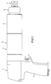
- Fig. 1 shows the entire power wrench in a side view.
- the power wrench is designed in the manner of a hand drill and has a drive device 1 which contains a rotary motor, not shown.
- the rotary motor can be switched on by pressing the operating lever 2.
- the drive device 1 is housed in a separate housing with a handle 3.
- a torque-controlled manual transmission 4 is fastened, the housing 5 of which is rotatably mounted relative to the housing of the drive device 1, so that the drive device 1 can be rotated with the handle 3 to any screw position.
- the torque-controlled manual transmission 4 is followed by a planetary gear which is inserted in the front housing part 6 of the power wrench.
- the front housing part 6 On the output shaft of the planetary gear, a head 7 is attached, on which a key nut for turning a screw can be attached.
- the front housing part 6 has a profile section 8 for fastening a support foot, not shown, which presses the front housing part and the housing 5 of the gearbox connected thereto against a stationary abutment.
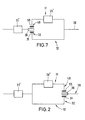
- Fig. 2 shows the functional diagram of the torque-operated manual transmission 4.
- the manual transmission has a first gear stage 21 ', the output shaft drives the output shaft 38 of the manual transmission via two individually switchable drive branches 11, 12.
- One of the two drive branches contains a second gear stage 26 '.
- Each of the two drive branches 11, 12 can be connected via a clutch 32, 48, one of the two clutches always being engaged and the other clutch being disengaged. Both clutches have a common coupling part 36. Is the on the output side of the second gear stage 26 'arranged clutch 48 is engaged, the output shaft 38 of the gearbox is driven with higher torque and lower speed than when the other clutch 32 is engaged and the torque without the second gear stage directly on the Output shaft 38 is transmitted.
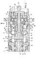
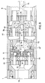
- FIG. 3 shows the torque-dependent manual transmission 4 constructed in accordance with the functional diagram from FIG. 2 in a sectional illustration.
- the housing 5 of the gearbox 4 is rotatably supported with a ball bearing 18 relative to the housing of the drive device 1.
- the drive shaft 19 driven by the rotary motor projects into the interior of the housing 5 from the end wall of the housing of the drive device 1.
- the wave-shaped shoulder of a sun gear 20 of the first gear stage 21 'forming the first planetary gear 21 is rotatably connected.
- the wavy shoulder of the sun gear 20 is mounted with the bearings 23, 23 'in the housing 5 of the gearbox.
- the toothing of the sun gear 20 is in engagement with the toothing of the planet gears 22, which are arranged around the sun gear 20.
- the planet gears 22 are mounted in a planet carrier 29, which also forms the output shaft 24 of the first gear 21. Furthermore, the planet carrier 29 carries the sun gear 25 of a second planetary gear 26 which is connected downstream of the first planetary gear 21 and which second gear stage 26 'forms. The sun gear 25 of the second planetary gear 26 drives the planet gears 27 which, like the planet gears 22 of the first planetary gear 21, engage in the internal toothing 17 of the housing 5.
- the output shaft 24 of the planet carrier 29 has a wave-shaped extension 30 which extends coaxially in the housing 5 and extends beyond the second planetary gear 26.
- the planet carrier 52 of the second planetary gear 26 is rotatably mounted on the shaft-shaped extension 30.
- the coupling body 31 of the first coupling 32 is connected in a rotationally fixed manner to the wave-shaped extension 30.
- the coupling body 31 contains a plurality of radially extending blind bores 50, in which ball catches 33 are inserted. In the position shown in FIG. 1, the balls 34 of the ball catches 33 engage in a driving path 35 of a movable coupling part 36.
- the coupling part 36 is surrounded by a cylindrical extension 37 of the output shaft 38, which with the ball bearing 54 on the shaft-shaped extension 30 and the Ball bearing 53 is mounted in the housing 5.
- two guide curves 39 are provided in the form of opposite triangular openings 40, which are shown in the top view in FIG. 4.
- the ends of two pin-shaped guide elements 41 protrude into these openings.
- the guide curves 39 and the guide elements 41 engaging therein ensure that the output shaft 38 always rotates with the coupling part 36, although slight relative rotations are possible within the openings formed by the guide curves 39 .
- Each of the openings 40 has the shape of a isosceles triangle (Fig.4), the tip of which is directed to the output shaft 38.
- the guide elements 41 connected to the movable coupling part 36 are pressed axially in the direction of the tips of the triangles by a spring 46 which is supported on the planet carrier 52 of the second planetary gear 26.
- the balls 34 of the ball catches 33 run in the driving path 35 of the coupling part 36, so that the coupling body 31 and the coupling part 36 are engaged.
- the triangular openings 40 are symmetrical with respect to the axis of the output shaft 38, so that each guide curve 39 forms two inclined flanks 40a, 40b with opposite bevels, along which the guide elements 41 can slide.
- the guide elements 41 disengage from the tips of the triangular guide curves 39 and slide along the flanks 40a or 40b, as a result of which the coupling part 36 counteracts the force of the spring 46 in the direction of the drive shaft 19 is moved.
- the balls 34 of the ball catches 33 slide into an idle track 47 provided on the side of the driving track 35 on the clutch part, so that the clutch part 36 is released from engagement with the clutch body 31.
- a clutch body 55 is attached to the planet carrier 52 of the second planetary gear 26 and forms a second clutch 48 with the movable clutch part 36. If the movable coupling part 36 in the direction of the coupling body 55 of the load torque occurring at the output shaft 38 is exceeded second clutch 48 moves, the claws 49, 49 'of the second clutch 48 are engaged and the first clutch 32 is disengaged.
- an axial bore 56 is provided, which runs through the sun gear 20 of the first planetary gear and the planet carrier 29 with the wave-shaped shoulder and the output shaft 38.
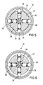
- the coupling body 31 contains the ball catches 33, each of which has a spring 60 contained in the radial blind bore 50 of the coupling body 31 and the balls 34 pressed outwards by the spring 60.
- the balls 34 run in the driving path 35, which is provided on the inside of the coupling body 31.
- This driving path 35 has a circumferentially varying diameter, so that there are recesses 61 into which the balls 34 can penetrate. For each ball 34 there is a recess 61 and all recesses are arranged such that all balls 34 can be located in the associated recess at the same time, as shown in FIG. 5.
- the coupling body 31 is in engagement with the coupling part 36 and the cylindrical extension of the output shaft 38 is carried along via the guide element 41. Since the clutch 32 can slip even when the balls 34 are in the driving path and are pressed into the blind bores 50 against the spring forces, increased security of the clutch against damage is achieved. Furthermore, drive shocks are prevented from being transmitted during the switching process.
- the idle track 47 has a constant diameter and has no recesses distributed around the circumferential surface.
- the power screwdriver described according to FIGS. 1-6 works as follows: To tighten a screw, a nut is placed on the head 7 of the power screwdriver, which is connected to the screw to be turned. The drive device 1 rotates the drive shaft 19, whereby the planet gears 22 of the first planetary gear 21 are driven. As long as the tightening torque is still low, the first clutch is engaged and the torque is transmitted via the planet carrier 29 of the first planetary gear 21 directly to the output shaft 38 of the torque-dependent manual transmission 4. The output shaft 38 drives the third downstream planetary gear, which is located in the front housing part 6 and moves the head 7 at a relatively high speed and a low torque.
- the common clutch part 36 of the two clutches 32, 48 shifts and the first clutch disengages.
- the second clutch 48 is engaged.
- the torque is now transmitted with the interposition of the second planetary gear 26, the planet carrier of which Coupling part 36 takes the output shaft 38 of the manual transmission.
- the rotation of the planet carrier 29 of the first planetary gear 21 is further reduced by the second downstream planetary gear 26, so that the head 7 of the power wrench is driven via the output shaft 38 at a lower speed but with a higher torque. This drive with higher torque and lower speed continues until the screw is tightened. There is no constant switching back and forth between high and low speed.
- Fig. 7 shows the functional diagram of a second embodiment of the torque-operated manual transmission.
- the manual transmission of the second exemplary embodiment also has two planetary gears 21, 26 and two clutches 32, 48.
- the only difference between the two manual transmissions is that in the manual transmission according to the second exemplary embodiment, the second clutch 48 is not arranged on the output side of the second planetary gear 26, but rather on the drive side thereof.
- Fig. 8 shows a section through the manual transmission according to the second embodiment.
- the drive shaft 19 protruding from the drive device 1 carries the sun gear 20 of the first planetary gear 21.
- the external toothing of the sun gear 20 engages with the internal teeth of the planet gears 22, which move the planet carrier 29.
- the planet carrier 29 drives, via the first clutch 32 with the ball catches 33, a shaft 64 which is axially rotatable in the gearbox and whose end piece facing away from the drive shaft 19 is toothed with the output shaft 38.
- the output shaft 38 is followed by the third planetary gear 76, which is located in the front housing part 6 of the power wrench.
- the coupling piece 36 of the first clutch 32 is displaced so that the first clutch disengages and the claws 49, 49 'of the second clutch 48 come into engagement, as a result of which the sun gear 25 of the second planetary gear 26 is taken away.
- the sun gear 25 engages in the external toothing of the planet gears 27 of the second planetary gear 26.
- the sun gear 75 of the third planetary gear 76 is driven by the planet carrier 52 of the second planetary gear 26.
- the planet carrier 52 has a shoulder 73 which surrounds the shaft 64 and has internal teeth. The internal toothing of the shoulder 73 is in engagement with the external toothing of the shaft 64, so that the shaft 64 rotates freely.
- the output shaft 38 rotates at a relatively high speed and low torque. If the first clutch is disengaged by shifting the coupling part 36 and the second clutch 48 is engaged, the second planetary gear 26 is connected downstream of the first planetary gear and the output shaft 38 is moved at a lower speed and higher torque.
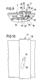
- the figures 9 and 10 show a locking device 77 with which the movable coupling part 36 can be blocked, so that the second coupling 48 is always engaged and the first coupling 32 is disengaged and the power wrench works with a relatively high torque and low speed in the load gear.
- a sliding piece 81 with a ball track 82 is attached to the end of the pin 79 which projects into the interior of the housing.
- the balls 83 located in the ball track 82 engage in recesses 84 of the movable coupling part.
- the sliding piece 81 is moved against the force of the spring 46 towards the coupling piece 55 of the second coupling 48, so that the claws 49, 49 'of the second coupling mesh.
- the sliding piece 81 is blocked by the locking device 77.
- the balls 83 can roll on the sliding piece 81 so that the coupling part 36 can move freely.
- FIGS. 11 and 12 show another embodiment of the first clutch 32 of the torque-dependent manual transmission in a sectional view.
- the coupling 32 differs from the couplings described with reference to FIGS. 5 and 6 in that the coupling body 31 with the springs 60 is arranged axially to the drive shaft. This achieves a compact design of the torque-controlled manual transmission.
- the axially arranged clutch body 31 of the first clutch 32 forms, together with the springs 60 and the balls 34, the common axially displaceable clutch part 36 for the first and the second clutch 32, 48.
- the common clutch part 36 is biased into the overdrive position shown in Fig. 11, in which the claws 49,49 'of the second clutch 48 are disengaged and the first clutch 32 is engaged.
- the balls 34 of the first clutch 32 which are biased by the springs 60, engage in hemispherical recesses 85 in a ring piece 86 which takes the output shaft of the power wrench with them. If the limit value of the load torque is exceeded, the common coupling part 36 moves in the axial direction, the claws 49, 49 'of the second coupling 48 engage and the balls 34 of the first coupling 32 slip out of the recesses 85 of the ring piece 86, so that the first clutch 32 is disengaged.
- the first clutch 32 can slip even when the balls 34 are in the recesses 85 of the ring piece 86 and are pressed against the spring forces into the blind bores 50 of the clutch body 31, increased security of the clutch against damage is achieved.
Landscapes
- Engineering & Computer Science (AREA)
- Mechanical Engineering (AREA)
- Details Of Spanners, Wrenches, And Screw Drivers And Accessories (AREA)
- Transmission Devices (AREA)
- Structure Of Transmissions (AREA)
Description
Die Erfindung betrifft einen Kraftschrauber nach dem Oberbegriff des Patentanspruchs 1.The invention relates to a power wrench according to the preamble of
Es ist bekannt zum Anziehen und Lösen von Schrauben elektrische oder druckmittelbetriebene Kraftschrauber einzusetzen. Da die zu drehende Schraube beim Eindrehen in den Gewindegang zunächst dem Kraftschrauber nur einen geringen Widerstand entgegensetzt, ist es zweckmäßig, die Schraube erst in einem Schnellgang mit hoher Drehzahl und kleinem Drehmoment zu drehen. Sobald sich der Widerstand der Schraube wesentlich erhöht hat, sollte der Kraftschrauber mit kleinerer Drehzahl und höherem Drehmoment angetrieben werden, um die Schraube festzuziehen. Dagegen ist beim Lösen einer Schraube zunächst ein hohes Drehmoment erforderlich und anschließend ein geringeres Drehmoment, bei dem mit höherer Drehzahl gearbeitet werden kann.It is known to use electric or pressure-powered power wrenches to tighten and loosen screws. Since the screw to be turned initially only provides a slight resistance to the power screwdriver when it is screwed into the thread, it is expedient to turn the screw only at high speed with high speed and low torque. As soon as the resistance of the screw has increased significantly, the power wrench should be driven at a lower speed and higher torque in order to tighten the screw. On the other hand, when loosening a screw, a high torque is required first and then a lower torque, at which higher speeds can be used.
Bekannt sind motorisch angetriebene Kraftschrauber, bei denen die Drehzahl und das mit der Drehzahl verbundene Drehmoment in Abhängigkeit von dem Schraubmoment manuell oder automatisch umgeschaltet werden kann. Bei Kraftschraubern mit automatischer Umschaltung, die mit einem Hydraulikmotor angetriebenen werden, wird der Vorlaufdruck gemessen und der Kraftschrauber auf höheres Drehmoment umgeschaltet, wenn der Vorlaufdruck einen bestimmten Grenzwert übersteigt. Bei elektromotorisch angetriebenen Kraftschraubern erfolgt die automatische Umschaltung des Schraubmomentes in Abhängigkeit von dem aufgenommenen Strom.Motor-driven power screwdrivers are known in which the speed and the torque associated with the speed can be switched over manually or automatically as a function of the screwing torque. For automatic screwdrivers that are driven by a hydraulic motor, the supply pressure is measured and the screwdriver is switched to a higher torque when the supply pressure exceeds a certain limit. In the case of power screwdrivers driven by an electric motor, the tightening torque is automatically switched depending on the current consumed.
Ferner sind Kraftschrauber bekannt, die eine Ratschenkupplung aufweisen. Bei niedrigem Schraubmoment ist die Ratschenkupplung eingekuppelt, so daß die Ausgangswelle über die Ratschenkupplung mit einer hohen Drehzahl gedreht wird. Wenn ein bestimmtes Grenzdrehmoment überschritten ist, rastet die Ratschenkupplung aus und die Ausgangswelle wird von einer langsamer drehenden Welle mitgenommen. Nachteilig ist hierbei, daß die Ratschenkupplung während des Arbeitens mit hohem Drehmoment starken mechanischen Belastungen ausgesetzt ist und ständig Schläge erzeugt.Furthermore, power screwdrivers are known which have a ratchet coupling. When the tightening torque is low, the ratchet clutch is engaged so that the output shaft is rotated at high speed via the ratchet clutch. When a certain limit torque is exceeded, the ratchet clutch disengages and the output shaft is carried along by a slower rotating shaft. The disadvantage here is that the ratchet clutch is exposed to strong mechanical loads while working with high torque and constantly generates impacts.
Bei den bekannten motorgetriebenen Kraftschraubern erfolgt die erforderliche Untersetzung der hohen Drehzahl der Motorausgangswelle über mehrere konventionelle Getriebestufen mit seitlich zueinander versetzt gelagerten Zahnrädern. Die Getriebestufen haben ein relativ großen Raumbedarf und verhältnismäßig hohes Gewicht.In the known motor-driven power screwdrivers, the required reduction of the high speed of the motor output shaft takes place via several conventional gear stages with toothed wheels which are offset laterally with respect to one another. The gear stages have a relatively large space requirement and a relatively high weight.
Ferner ist ein Krafschrauber bekannt (DE 37 20 633 A1), der drei zwischen einer Antriebswelle und einer Abtriebswelle in Reihe angeordnete Planetengetriebe aufweist. Die Ringräder der eingangs- und ausgangsseitigen Planetengetriebe sind in dem Gehäuse des Kraftschraubers sowohl axial verschiebbar als auch drehbar gelagert, wobei das Ringrad des eingangsseitigen Planetengetriebes durch eine Kupplung in einer ersten Stellung am Planetenradträger und in einer zweiten Stellung am Gehäuse festlegbar ist. Bei geringem Schraubmoment befindet sich die Kupplung in der ersten Stellung, so daß das Ringrad des eingangsseitigen Planetengetriebes reibschlüssig am Planetenträger festgelegt ist und zusammen mit diesem mit derselben relativ hohen Drehzahl rotiert.Furthermore, a power wrench is known (
Bei Überschreiten eines bestimmten Schraubmoments wird die Kupplung durch einen durch Federn vorgespannten Nockenmechanismus in die zweite Stellung bewegt. Dadurch wird das Ringrad des eingangsseitigen Planetengetriebes gegen Drehung im Gehäuse blockiert und die Klemmkraft zwischen Ringrad und Planetenträger aufgehoben. Der Planetenträger dreht sich folglich mit relativ geringer Drehzahl. Ferner weist der Kraftschrauber noch eine zweite, als Rutschkupplung ausgebildete Kupplung auf, die bei Überschreiten eines maximalen Schraubmoments die Drehmomentübertragung unterbricht.When a certain torque is exceeded, the clutch is moved into the second position by a spring-loaded cam mechanism. As a result, the ring gear of the input-side planetary gear is blocked against rotation in the housing and the clamping force between the ring gear and the planet carrier is released. The planet carrier consequently rotates at a relatively low speed. Furthermore, the power wrench also has a second clutch designed as a slip clutch, which interrupts the torque transmission when a maximum torque is exceeded.
Nachteilig ist, daß der Schaltmechanismus zum Umschalten des Übersetzungsverhältnisses der eingangsseitigen Getriebestufe relativ aufwendig ist. So sind die Ringräder der Planetengetriebe sowohl drehbeweglich als auch axial verschiebbar in dem Gehäuse gelagert und müssen durch einen komplizierten Mechanismus derart gegeneinander verschoben werden, daß sich das Ringrad des eingangsseitigen Planetengetriebes entweder am Gehäuse oder am Planetenträger festlegen läßt. Die Kupplung, die das Ringrad des eingangsseitigen Planetengetriebes am Planetenträger bzw. am Gehäuse festlegt, bildet mit dem Planetengetriebe eine bauliche Einheit, so daß der Aufbau des Schaltmechanismus relativ kompliziert ist. Ferner müssen die axial beweglichen Teile mit geringen Fertigungstoleranzen hergestellt werden. Es besteht die Gefahr, daß die axial verschiebbar gelagerten Teile sich in ihren Führungen verklemmen und den Schaltmechanismus blockieren.The disadvantage is that the switching mechanism for switching the gear ratio of the input-side gear stage is relatively complex. Thus, the ring gears of the planetary gears are both rotatably and axially displaceably mounted in the housing and must be shifted against each other by a complicated mechanism in such a way that the ring gear of the input-side planetary gear can be fixed either on the housing or on the planet carrier. The clutch, which fixes the ring gear of the input-side planetary gear on the planet carrier or on the housing, forms a structural unit with the planetary gear, so that the structure of the switching mechanism is relatively complicated. Furthermore, the axially movable parts have to be manufactured with low manufacturing tolerances. There is a risk that the axially displaceable parts jam in their guides and block the switching mechanism.
Ein Kraftschrauber mit einem drehmomentabhängigen Schaltgetriebe, der im Oberbegriff des Patentanspruchs 1 angegebenen Art ist aus US-A-3 430 521 bekannt. Der bekannte Kraftschrauber weist eine erste ein Planetengetriebe enthaltene Getriebestufe und eine in Reihe mit der ersten Getriebestufe angeordnete zweite Getriebestufe auf. Die Getriebestufen bilden zwei parallele Antriebszweige, die ständig mitlaufen. Über eine erste Kupplung kann der erste Antriebszweig an die Abtriebswelle des Kraftschrauber und über eine zweite Kupplung kann der zweite Antriebszweig an die Abtriebswelle angekuppelt werden. Die Kupplungen weisen einen Kupplungskörper auf, der aus zwei miteinander gekoppelten, gegenläufigen Kupplungsteilen besteht, die auf der Abtriebswelle in Axialrichtung verschiebbar gelagert sind und mit entsprechenden Kupplungsteilen der beiden Kupplungszweige in Eingriff gebracht werden können. Die Kupplungsflächen der Kupplungsteile sind zahnförmig ausgebildet. Bei Überschreiten eines bestimmten Grenzdrehmoments wird das innere Kupplungsteil auf der Abtriebswelle zurückgedrückt, so daß die eine Kupplung ausgekuppelt ist. Gleichzeitig wird das äußere Kupplungsteil, das an das innere Kupplungsteil gekoppelt ist, vorgeschoben, so daß die andere Kupplung eingekuppelt ist und sich die Abtriebswelle mit kleinerer Drehzahl und größerem Drehmoment dreht.A power wrench with a torque-dependent manual transmission, the type specified in the preamble of
Nachteilig ist bei dem bekannten Kraftschrauber, daß ein relativ aufwendiger Mechanismus erforderlich ist, um den Kraftschrauber aus der Getriebestellung mit kleinerer Drehzahl und größerem Drehmoment wieder in die Getriebestellung mit größerer Drehzahl und kleinerem Drehmoment zurückschalten zu können.A disadvantage of the known power screwdriver is that a relatively complex mechanism is required in order to be able to switch the power screwdriver back from the gear position with lower speed and greater torque back to the gear position with higher speed and smaller torque.
Der Erfindung liegt die Aufgabe zugrunde, einen Kraftschrauber der im Oberbegriff des Patentanspruchs 1 angegebenen Art zu schaffen, der einen einfachen Aufbau hat und störungsfrei arbeitet.The invention has for its object to provide a power wrench of the type specified in the preamble of
Die Lösung dieser Aufgabe erfolgt erfindungsgemäß mit den im Patentanspruch 1 angegebenen Merkmalen.This object is achieved according to the invention with the features specified in
Bei dem erfindungsgemäßen Kraftschrauber stehen zur Übertragung des Drehmoments zwei separate Antriebszweige mit unterschiedlichem Übersetzungsverhältnis zur Verfügung, die ständig mitlaufen. In Abhängigkeit vom Schraubmoment kann dann wahlweise auf den einen oder den anderen Antriebszweig zugegriffen werden, um die Abtriebswelle mit höherer oder niedriger Drehzahl anzutreiben.In the power wrench according to the invention, two separate drive branches with different transmission ratios are available for transmission of the torque, which run continuously. Depending on the tightening torque, one or the other drive branch can then be accessed to drive the output shaft at a higher or lower speed.
Die Umschaltung erfolgt durch zwei Kupplungen, von denen je eine in einem Antriebszweig angeordnet ist. Das gemeinsame bewegbare Kupplungsteil beider Kupplungen ist derart vorgespannt, daß eine der beiden Kupplungen in Eingriff und die andere Kupplung außer Eingriff ist. Die Drehzahl der Antriebswelle des Schaltgetriebes wird unabhängig von dem Schraubmoment des Kraftschraubers immer über eine erste Getriebestufe untersetzt. Bei geringem Schraubmoment (Lastmoment) ist der Ausgang der ersten Getriebestufe direkt mit der Abtriebswelle verbunden, so daß die Abtriebswelle mit einer relativ hohen Drehzahl angetrieben wird. Dabei ist die Kraftübertragung über den anderen Antriebszweig unterbrochen. Sobald ein bestimmtes Grenzdrehmoment überschritten wird, nimmt das gemeinsame bewegbare Kupplungsteil die andere Stellung ein. Die Übertragung des Drehmoments der Antriebswelle erfolgt nun über die zweite Getriebestufe mit einer geringeren Drehzahl und höherem Drehmoment. Das Umschalten erfolgt ohne externe Steuerung durch eine als Überlastkupplung ausgebildete Umschaltkupplung oder Doppelkupplung, deren Kupplungsteil immer mit einem der Antriebszweige gekoppelt ist und somit niemals leerläuft.Switching takes place via two clutches, one of which is arranged in a drive branch. The common movable coupling part of both clutches is biased such that one of the two clutches is engaged and the other clutch is disengaged. The speed of the drive shaft of the gearbox is always reduced regardless of the torque of the power wrench via a first gear stage. If the tightening torque is low (load torque), the output of the first gear stage is connected directly to the output shaft, so that the output shaft is driven at a relatively high speed. The power transmission via the other drive branch is interrupted. As soon as a certain limit torque is exceeded, the joint movable coupling part assumes the other position. The transfer of the torque of the drive shaft now takes place via the second gear stage with a lower speed and higher torque. The changeover takes place without external control by means of a changeover clutch or double clutch designed as an overload clutch, the clutch part of which is always coupled to one of the drive branches and thus never runs idle.
Die Getriebestufen sind einfach aufzubauen, da sie ein festes Übersetzungsverhältnis aufweisen und ein störanfälliger aufwendiger Steuerungsmechanismus zur Veränderung des Übersetzungsverhältnisses mindestens einer der beiden Getriebestufen entfallen kann.The gear stages are easy to set up, since they have a fixed transmission ratio and an elaborate control mechanism, which is prone to malfunctions, for changing the transmission ratio can be dispensed with at least one of the two transmission stages.
Die Verwendung von Planetengetrieben ermöglicht eine kompakte rohrförmige Bauweise der drehmomentabhängig betätigten Kupplung bei geringem Gewicht. An der Abtriebswelle ist bei dem erfindungsgemäßen Kraftschrauber eine Führungskurve vorgesehen, in die ein an dem Kupplungsteil angebrachtes Führungselement eingreift. Bei Überschreiten des Grenzdrehmomentes wird das gemeinsame Kupplungsteil entgegen der Vorspannung axial verschoben. Die Vorspannung des Kupplungsteils kann durch eine Federvorrichtung oder auch hydraulisch aufgebracht werden. Vorzugsweise kann diese Vorspannung durch externe Einstellung verändert werden, um die Höhe des Lastmoments, bei dem die Umschaltung erfolgt, verstellen zu können.The use of planetary gears enables a compact tubular construction of the torque-dependent clutch with a low weight. In the power screwdriver according to the invention, a guide curve is provided on the output shaft, in which a guide element attached to the coupling part engages. If the limit torque is exceeded, the common coupling part is axially displaced against the preload. The preload of the coupling part can be applied by a spring device or also hydraulically. This preload can preferably be changed by external adjustment in order to be able to adjust the level of the load torque at which the switchover takes place.
Vorteilhafterweise ist eine der beiden Kupplungen als Kugelkupplung ausgebildet. Bei der Kugelkupplung erfolgt die Kopplung zwischen einem mit dem Planetenträger des ersten Planetengetriebes in Verbindung stehenden Kupplungskörper und dem bewegbaren Kupplungsteil durch federgespannte Kugeln, die gegen eine unrunde Bahn gedrückt werden. Eine solche Kugelkupplung bildet eine Rutschkupplung, bei der der Kupplungskörper und das Kupplungsteil sich relativ zueinander bewegen können. Um im Falle einer solchen Relativbewegung die Belastung der Kupplungskomponenten zu verringern und eine bessere Ausnutzung der Antriebsenergie zu erhalten, ist angrenzend an eine die Ausnehmungen der Kugelkupplung enthaltene Mitnahmebahn eine freie Leerlaufbahn vorgesehen, die die Kugeln aufnimmt, wenn die Kupplung des zweiten Antriebszweiges in Eingriff ist.One of the two couplings is advantageously designed as a ball coupling. In the ball coupling, the coupling between a coupling body, which is connected to the planet carrier of the first planetary gear, and the movable coupling part takes place by spring-loaded balls which act against a non-circular one Web are pressed. Such a ball coupling forms a slip clutch in which the coupling body and the coupling part can move relative to one another. In order to reduce the load on the coupling components in the event of such a relative movement and to obtain a better use of the drive energy, a free idling path is provided adjacent to a carrier track which contains the recesses of the ball coupling and which receives the balls when the coupling of the second drive branch is engaged .
Der Planetenträger des ersten Planetengetriebes weist vorteilhafterweise eine koaxial zur Antriebswelle verlaufende Ausgangswelle mit einem sich über die zweite Getriebestufe hinaus erstreckenden Ansatz auf. Die Ausgangswelle kann das Sonnenrad des zweiten nachgeschalteten Planetengetriebes tragen, während der Ansatz mit dem Kupplungskörper der ersten Kupplung verbunden ist. Die koaxiale Anordnung der beiden Getriebestufen und der Kupplungen schafft eine kompakte Bauform des schaltbaren Getriebes.The planet carrier of the first planetary gear advantageously has an output shaft which runs coaxially to the drive shaft and has an extension which extends beyond the second gear stage. The output shaft can carry the sun gear of the second downstream planetary gear, while the shoulder is connected to the clutch body of the first clutch. The coaxial arrangement of the two gear stages and the clutches creates a compact design of the switchable gear.
Im folgenden werden unter Bezugnahme auf die Zeichnungen zwei Ausführungsbeispiele der Erfindung näher erläutert.Two exemplary embodiments of the invention are explained in more detail below with reference to the drawings.
Es zeigen:
- Fig. 1
- eine Seitenansicht des gesamten Kraftschraubers,
- Fig. 2
- ein Funktionsschema eines drehmomentabhängig betätigten Schaltgetriebes
- Fig. 3
- einen Schnitt durch das drehmomentabhängig betätigte Schaltgetriebe gemäß Fig. 2, dessen zweite Kupplung auf der Abtriebsseite der zweiten Getriebestufe angeordnet ist,
- Fig. 4
- eine Draufsicht auf das Schaltgetriebe aus Fig. 3 in teilweiser geschnittener Darstellung,
- Fig. 5
- einen Schnitt entlang der Linie V-V von Fig. 3,
- Fig. 6
- einen Schnitt entlang der Linie VI-VI von Fig. 3,
- Fig. 7
- ein Funktionsschema einer zweiten Ausführungsform des drehmomentabhängig betätigten Schaltgetriebes,
- Fig. 8
- einen Schnitt durch das drehmomentabhängig betätigte Schaltgetriebe gemäß Fig. 7, dessen zweite Kupplung auf der Antriebsseite der zweiten Getriebestufe angeordnet ist,
- Fig. 9
- eine Arretiervorrichtung zum Blockieren des bewegbaren Kupplungsteils,
- Fig. 10
- eine Draufsicht auf ein drehmomentabhängig betätigtes Schaltgetriebe mit einer Arretiervorrichtung,
- Fig. 11
- eine andere Ausführungsform der ersten Kupplung des drehmomentabhängig betätigten Schaltgetriebes in geschnitter Darstellung, und
- Fig. 12
- einen Schnitt entlang der Linie XII-XII von Fig. 11
- Fig. 1
- a side view of the entire power wrench,
- Fig. 2
- a functional diagram of a torque-operated manual transmission
- Fig. 3
- 2 shows a section through the torque-controlled manual transmission according to FIG. 2, the second clutch of which is arranged on the output side of the second transmission stage,
- Fig. 4
- 3 shows a top view of the manual transmission from FIG. 3 in a partially sectioned illustration,
- Fig. 5
- 4 shows a section along the line VV from FIG. 3,
- Fig. 6
- 4 shows a section along the line VI-VI from FIG. 3,
- Fig. 7
- 2 shows a functional diagram of a second embodiment of the torque-dependent manual transmission,
- Fig. 8
- 7 shows a section through the torque-dependent manual transmission according to FIG. 7, the second clutch of which is arranged on the drive side of the second transmission stage,
- Fig. 9
- a locking device for blocking the movable coupling part,
- Fig. 10
- 2 shows a top view of a torque-dependent manual transmission with a locking device,
- Fig. 11
- another embodiment of the first clutch of the torque-operated manual transmission in a sectional view, and
- Fig. 12
- a section along the line XII-XII of Fig. 11th
Fig. 1 zeigt den gesamten Kraftschrauber in der Seitenansicht. Der Kraftschrauber ist nach Art einer Handbohrmaschine ausgebildet und weist eine Antriebseinrichtung 1 auf, die einen nicht dargestellten Drehmotor enthält. Der Drehmotor kann durch Drücken des Betätigungshebels 2 eingeschaltet werden. Die Antriebseinrichtung 1 ist in einem separaten Gehäuse mit einem Griffstück 3 untergebracht. An dem Gehäuse der Antriebseinrichtung 1 ist ein drehmomentabhängig betätigtes Schaltgetriebe 4 befestigt, dessen Gehäuse 5 gegenüber dem Gehäuse der Antriebseinrichtung 1 drehbar gelagert ist, so daß die Antriebseinrichtung 1 mit dem Griffstück 3 auf eine beliebige Schraubposition verdreht werden kann. Dem drehmomentabhängig betätigten Schaltgetriebe 4 ist ein Planetenradgetriebe nachgeschaltet, das in dem vorderen Gehäuseteil 6 des Kraftschraubers eingesetzt ist. An der Ausgangswelle des Planetenradgetriebes ist ein Kopf 7 befestigt, an dem eine Schlüsselnuß zum Drehen einer Schraube angebracht werden kann. Das vordere Gehäuseteil 6 weist einen Profilabschnitt 8 für die Befestigung eines nicht dargestellten Stützfußes auf, der das vordere Gehäuseteil und das damit verbundene Gehäuse 5 des Schaltgetriebes gegen ein ortfestes Widerlager drückt.Fig. 1 shows the entire power wrench in a side view. The power wrench is designed in the manner of a hand drill and has a
Fig. 2 zeigt das Funktionsschema des drehmomentabhängig betätigten Schaltgetriebes 4. Das Schaltgetriebe weist eine erste Getriebestufe 21′ auf, dessen Ausgangswelle über zwei einzeln einschaltbare Antriebszweige 11,12 die Abtriebswelle 38 des Schaltgetriebes antreibt.Fig. 2 shows the functional diagram of the torque-operated
Einer der beiden Antriebszweige enthält eine zweite Getriebestufe 26′. Jeder der beiden Antriebszweige 11,12 ist über eine Kupplung 32,48 zuschaltbar, wobei immer eine der beiden Kupplungen in Eingriff und die andere Kupplung außer Eingriff ist. Beide Kupplungen weisen ein gemeinsames Kupplungsteil 36 auf. Ist die auf der Abtriebsseite der zweiten Getriebestufe 26′ angeordnete Kupplung 48 in Eingriff, so wird die Abtriebswelle 38 des Schaltgetriebes mit höherem Drehmoment und niedrigerer Drehzahl angetrieben als wenn die andere Kupplung 32 in Eingriff ist und das Drehmoment ohne Zwischenschaltung der zweiten Getriebestufe direkt auf die Abtriebswelle 38 übertragen wird.One of the two drive branches contains a second gear stage 26 '. Each of the two
Fig. 3 zeigt das gemäß dem Funktionsschema aus Fig. 2 aufgebaute drehmomentabhängig betätigte Schaltgetriebe 4 in geschnittener Darstellung. Das Gehäuse 5 des Schaltgetriebes 4 ist mit einem Kugellager 18 drehbar gegenüber dem Gehäuse der Antriebseinrichtung 1 gelagert. Aus der Stirnwand des Gehäuses der Antriebseinrichtung 1 ragt die von dem Drehmotor angetriebene Antriebswelle 19 in das Innere des Gehäuses 5 hinein. Mit der Antriebswelle 19 ist der wellenförmige Absatz eines Sonnenrades 20 des die erste Getriebestufe 21′ bildenden ersten Planetengetriebes 21 drehfest verbunden. Der wellenförmige Absatz des Sonnenrades 20 ist mit den Lagern 23,23′ im Gehäuse 5 des Schaltgetriebes gelagert. Die Verzahnung des Sonnenrades 20 ist mit den Verzahnungen der Planetenräder 22 in Eingriff, welche um das Sonnenrad 20 herum angeordnet sind. Die Planetenräder 22 sind in einem Planetenträger 29 gelagert, der auch die Ausgangswelle 24 des ersten Getriebes 21 bildet. Ferner trägt der Planetenträger 29 das Sonnenrad 25 eines zweiten, dem ersten Planetengetriebe 21 nachgeschalteten Planetengetriebes 26, welches die zweite Getriebestufe 26′ bildet. Das Sonnenrad 25 des zweiten Planetengetriebes 26 treibt die Planetenräder 27, die ebenso wie die Planetenräder 22 des ersten Planetengetriebes 21 in die Innenverzahnung 17 des Gehäuses 5 greifen.FIG. 3 shows the torque-dependent
Die Ausgangswelle 24 des Planetenträgers 29 weist einen koaxial im Gehäuse 5 verlaufenden und sich über das zweite Planetengetriebe 26 hinaus erstreckenden wellenförmigen Ansatz 30 auf. Mit den Kugellagern 51,51′ ist der Planetenträger 52 des zweiten Planetengetriebes 26 drehbar auf dem wellenförmigen Ansatz 30 gelagert. Mit dem wellenförmigen Ansatz 30 ist der Kupplungskörper 31 der ersten Kupplung 32 drehfest verbunden. Der Kupplungskörper 31 enthält mehrere radial verlaufende Sackbohrungen 50, in denen Kugelrasten 33 eingesetzt sind. In der in Fig. 1 dargestellten Position greifen die Kugeln 34 der Kugelrasten 33 in eine Mitnahmebahn 35 eines bewegbaren Kupplungsteils 36. Das Kupplungsteil 36 wird von einem zylindrischen Ansatz 37 der Abtriebswelle 38 umgeben, welche mit dem Kugellager 54 auf dem wellenförmigen Ansatz 30 und dem Kugellager 53 im Gehäuse 5 gelagert ist.The
In der Umfangsfläche des zylindrischen Ansatzes 37 sind zwei Führungskurven 39 in Form einander gegenüberliegender dreieckiger Öffnungen 40 vorgesehen, die in der Aufsicht in Fig. 4 gezeigt sind. In diese Öffnungen ragen die Enden zweier stiftförmiger Führungselemente 41. Durch die Führungskurven 39 und die darin eingreifenden Führungselemente 41 wird erreicht, daß die Abtriebswelle 38 sich stets mit dem Kupplungsteil 36 dreht, wobei jedoch innerhalb der von den Führungskurven 39 gebildeten Öffnungen geringe Relativdrehungen möglich sind. Jede der Öffnungen 40 hat die Form eines gleichschenkligen Dreiecks (Fig.4), dessen Spitze auf die Abtriebswelle 38 gerichtet ist. Die mit dem bewegbaren Kupplungsteil 36 verbundenen Führungselemente 41 werden durch eine sich an dem Planetenträger 52 des zweiten Planetengetriebes 26 abstützende Feder 46 axial in Richtung auf die Spitzen der Dreiecke gedrückt. In der in den Fign. 3 und 4 dargestellten Schnellgangposition laufen die Kugeln 34 der Kugelrasten 33 in der Mitnahmebahn 35 des Kupplungsteils 36, so daß der Kupplungskörper 31 und das Kupplungsteil 36 in Eingriff sind.In the peripheral surface of the
Die dreieckförmigen Öffnungen 40 sind bezogen auf die Achse der Abtriebswelle 38 symmetrisch, so daß jede Führungskurve 39 zwei schräge Flanken 40a,40b mit entgegengesetzten Abschrägungen bildet, an denen die Führungselemente 41 entlanggleiten können. Wenn das an der Abtriebswelle 38 auftretende Lastmoment einen bestimmten Grenzwert übersteigt, lösen sich die Führungselemente 41 aus den Spitzen der dreieckigen Führungskurven 39 und gleiten an den Flanken 40a oder 40b entlang, wodurch das Kupplungsteil 36 entgegen der Kraft der Feder 46 in Richtung auf die Antriebswelle 19 verschoben wird. Dabei gleiten die Kugeln 34 der Kugelrasten 33 in eine seitlich von der Mitnahmebahn 35 an dem Kupplungsteil vorgesehene Leerlaufbahn 47, so daß sich das Kupplungsteil 36 von dem Eingriff mit dem Kupplungskörper 31 löst.The
An dem Planetenträger 52 des zweiten Planetengetriebes 26 ist ein Kupplungskörper 55 angebracht, der mit dem bewegbaren Kupplungsteil 36 eine zweite Kupplung 48 bildet. Wenn sich das bewegbare Kupplungsteil 36 bei Überschreiten des an der Abtriebswelle 38 auftretenden Lastmoments in Richtung auf den Kupplungskörper 55 der zweiten Kupplung 48 bewegt, sind die Klauen 49, 49′ der zweiten Kupplung 48 in Eingriff und die erste Kupplung 32 ist außer Eingriff. In dem Schaltgetriebe ist eine axiale Bohrung 56 vorgesehen, die durch das Sonnenrad 20 des ersten Planetengertriebes und den Planetenträger 29 mit dem wellenförmigen Ansatz sowie die Abtriebswelle 38 verläuft.A
Fig. 5 zeigt die erste Kupplung 32 im Schnitt, welche aus dem Kupplungskörper 31 und dem verschiebbaren Kupplungsteil 36 gebildet wird. Der Kupplungskörper 31 enthält die Kugelrasten 33, von denen jede eine in der radialen Sackbohrung 50 des Kupplungskörpers 31 enthaltene Feder 60 und die von der Feder 60 nach außen gedrückte Kugeln 34 aufweist. Die Kugeln 34 laufen in der Mitnahmebahn 35, die an der Innenseite des Kupplungskörpers 31 vorgesehen ist. Diese Mitnahmebahn 35 hat einen umfangsmäßig variierenden Durchmesser, so daß sich Ausnehmungen 61 ergeben, in die die Kugeln 34 eindringen können. Für jede Kugel 34 ist eine Ausnehmung 61 vorhanden und alle Ausnehmungen sind so angeordnet, daß sich alle Kugeln 34 gleichzeitig in der zugehörigen Ausnehmung befinden können, wie in Fig. 5 dargestellt ist. Solange die Kugeln 34 durch die Kraft der Federn 60 in den Ausnehmungen gedrückt gehalten werden, ist der Kupplungskörper 31 mit dem Kupplungsteil 36 in Eingriff und der zylindrische Ansatz der Abtriebswelle 38 wird über das Führungselement 41 mitgenommen. Da die Kupplung 32 auch dann durchrutschen kann, wenn sich die Kugeln 34 in der Mitnahmebahn befinden und entgegen den Federkräften in die Sackbohrungen 50 gedrückt werden, wird eine erhöhte Sicherheit der Kupplung gegen Beschädigungen erreicht. Ferner wird verhindert, daß beim Schaltvorgang Antriebsstöße übertragen werden.5 shows the
Fig. 6 zeigt die an die Mitnahmebahn 35 angrenzende Leerlaufbahn 47. Die Leerlaufbahn 47 hat einen konstanten Durchmesser und weist keine um die Umfangsfläche verteilten Ausnehmungen auf. Wenn das Kupplungsteil 36, das bei geringem Lastmoment in Richtung auf die Abtriebswelle gedrückt wird, sich entgegen der Kraft der Feder 46 in Richtung auf den Kupplungskörper 55 der zweiten Kupplung 48 bewegt, gelangen die Kugeln 34 von der Mitnahmebahn 35 in die Leerlaufbahn 47. In diesem Zustand ist der Kupplungskörper 31 rotatorisch von dem Kupplungsteil 36 abgekuppelt, während die Klauen 49,49′ der zweiten Kupplung 48 in Eingriff sind.6 shows the
Der beschriebene Kraftschrauber nach den Figuren 1 - 6 arbeitet wie folgt: Zum Festziehen einer Schraube wird auf den Kopf 7 des Kraftschraubers eine Nuß aufgesetzt, die mit der zu drehenden Schraube verbunden wird. Die Antriebseinrichtung 1 dreht die Antriebswelle 19, wodurch die Planetenräder 22 des ersten Planetengetriebes 21 angetrieben werden. Solange das Schraubmoment noch gering ist, ist die erste Kupplung eingekuppelt und das Drehmoment wird über den Planetenträger 29 des ersten Planetengetriebes 21 direkt auf die Abtriebswelle 38 des drehmomentabhängig betätigten Schaltgetriebes 4 übertragen. Die Abtriebswelle 38 treibt das dritte nachgeschaltete Planetengetriebe, welches sich in dem vorderen Gehäuseteil 6 befindet und den Kopf 7 mit einer relativ hohen Drehzahl und einem geringen Drehmoment bewegt. Wird der Grenzwert des Lastmoments überschritten, verschiebt sich das gemeinsame Kupplungsteil 36 der beiden Kupplungen 32,48 und die erste Kupplung kommt außer Eingriff. Gleichzeitig wird die zweite Kupplung 48 eingekuppelt. Die Übertragung des Drehmoments erfolgt nun unter Zwischenschaltung des zweiten Planetengetriebes 26, dessen Planetenträger über das Kupplungsteil 36 die Abtriebswelle 38 des Schaltgetriebes mitnimmt. Die Drehung des Planetenträgers 29 des ersten Planetengetriebes 21 wird durch das zweite nachgeschaltete Planetengetriebe 26 nochmals untersetzt, so daß der Kopf 7 des Kraftschraubers über die Abtriebswelle 38 mit geringerer Drehzahl, aber höherem Drehmoment angetrieben wird. Dieser Antrieb mit höherem Drehmoment und geringerer Drehzahl wird solange fortgesetzt, bis die Schraube festgezogen ist. Dabei erfolgt kein ständiges Hin- und Herschalten zwischen hoher und niedriger Drehzahl.The power screwdriver described according to FIGS. 1-6 works as follows: To tighten a screw, a nut is placed on the head 7 of the power screwdriver, which is connected to the screw to be turned. The
Fig. 7 zeigt das Funktionsschema eines zweiten Ausführungsbeispiels des drehmomentbetätigten Schaltgetriebes. Im Vergleich zu dem Schaltgetriebe gemäß dem ersten Ausführungsbeispiel weist das Schaltgetriebe des zweiten Ausführungsbeispiels ebenfalls zwei Planetengetriebe 21,26 und zwei Kupplungen 32,48 auf. Der einzige Unterschied zwischen den beiden Schaltgetrieben liegt darin, daß bei dem Schaltgetriebe nach dem zweiten Ausführungsbeispiel die zweite Kupplung 48 nicht auf der Abtriebsseite des zweiten Planetengetriebes 26, sondern auf dessen Antriebsseite angeordnet ist.Fig. 7 shows the functional diagram of a second embodiment of the torque-operated manual transmission. In comparison to the manual transmission according to the first exemplary embodiment, the manual transmission of the second exemplary embodiment also has two
Fig. 8 zeigt einen Schnitt durch das Schaltgetriebe gemäß dem zweiten Ausführungsbeispiel. Die aus der Antriebseinrichtung 1 vorstehende Antriebswelle 19 trägt das Sonnenrad 20 des ersten Planetengetriebes 21. Die Außenverzahnung des Sonnenrads 20 ist mit den Innenverzahnungen der Planetenräder 22 in Eingriff, die den Planetenträger 29 bewegen. Der Planetenträger 29 treibt über die erste Kupplung 32 mit den Kugelrasten 33 eine in dem Schaltgetriebe axial drehbare Welle 64, deren der Antriebswelle 19 abgewandtes Endstück mit der Abtriebswelle 38 verzahnt ist. Der Abtriebswelle 38 ist das dritte Planetengetriebe 76 nachgeschaltet, das sich in dem vorderen Gehäuseteil 6 des Kraftschraubers befindet. Bei Überschreiten eines bestimmten Lastmoments an der Abtriebswelle 38 wird das Kupplungsstück 36 der ersten Kupplung 32 verschoben, so daß die erste Kupplung außer Eingriff kommt und die Klauen 49,49′ der zweiten Kupplung 48 in Eingriff gelangen, wodurch das Sonnenrad 25 des zweiten Planetengetriebes 26 mitgenommen wird. Das Sonnenrad 25 greift in die Außenverzahnungen der Planetenräder 27 des zweiten Planetengetriebes 26. Solange die erste Kupplung 32 außer Eingriff ist und die zweite Kupplung 48 in Eingriff ist, wird das Sonnenrad 75 des dritten Planetengetriebes 76 von dem Planetenträger 52 des zweiten Planetengetriebes 26 angetrieben. Der Planetenträger 52 weist einen die Welle 64 umschließenden Absatz 73 mit einer Innenverzahnung auf. Die Innenverzahnung des Absatzes 73 ist mit der Außenverzahnung der Welle 64 in Eingriff, so daß die Welle 64 frei mitdreht.Fig. 8 shows a section through the manual transmission according to the second embodiment. The
Wenn die erste Kupplung 32 in Eingriff ist, dreht sich die Abtriebswelle 38 mit relativ hoher Drehzahl und geringem Drehmoment. Wird die erste Kupplung durch Verschieben des Kupplungsteils 36 ausgekuppelt und die zweite Kupplung 48 eingekuppelt, so ist dem ersten Planetengetriebe das zweite Planetengetriebe 26 nachgeschaltet und die Abtriebswelle 38 wird mit geringerer Drehzahl und höherem Drehmoment bewegt.When the first clutch 32 is engaged, the
Die Fign. 9 und 10 zeigen eine Arretiervorrichtung 77, mit der das bewegbare Kupplungsteil 36 blockiert werden kann, so daß immer die zweite Kupplung 48 eingekuppelt und die erste Kupplung 32 ausgekuppelt ist und der Kraftschrauber im Lastgang mit relativ großem Drehmoment und kleiner Drehzahl arbeitet. An der Außenseite des Kupplungsgehäuses 5 befindet sich ein Stellring 78. An dem Stellring 78 ist ein in das Gehäuseinnere greifender Stift 79 angebracht, der in einer in der Gehäusewand vorgesehenen Schaltkurve 80 (Fig. 10) geführt ist. An dem in das Gehäuseinnere ragenden Ende des Stifts 79 ist ein Schiebestück 81 mit einer Kugelbahn 82 angebracht. Die in der Kugelbahn 82 befindlichen Kugeln 83 greifen in Ausnehmungen 84 des bewegbaren Kupplungsteils. Durch Verdrehen des Stellrings 78 wird das Schiebestück 81 entgegen der Kraft der Feder 46 auf das Kupplungsstück 55 der zweiten Kupplung 48 zubewegt, so daß die Klauen 49,49′ der zweiten Kupplung ineinandergreifen. In dieser Stellung, in der die zweite Kupplung 48 eingekuppelt und die erste Kupplung 32 ausgekuppelt ist, ist das Schiebestück 81 durch die Arretiervorrichtung 77 blockiert. Solange das Schiebestück jedoch in Richtung auf die Abtriebswelle des Schaltgetriebes verschoben ist, können die Kugeln 83 auf dem Schiebestück 81 abrollen, so daß sich das Kupplungsteil 36 frei bewegen kann.The figures 9 and 10 show a
Die Figuren 11 und 12 zeigen eine andere Ausführungsform der ersten Kupplung 32 des drehmomentabhängig betätigten Schaltgetriebes in geschnitter Darstellung. Die Kupplung 32 unterscheidet sich von der unter Bezugnahme auf die Figuren 5 und 6 beschriebenen Kupplungen dadurch, daß der Kupplungskörper 31 mit den Federn 60 axial zur Antriebeswelle angeordnet ist. Damit wird eine kompakte Bauform des drehmomentabhängig betätigten Schaltgetriebes erreicht.FIGS. 11 and 12 show another embodiment of the
Der axial angeordnete Kupplungskörper 31 der ersten Kupplung 32 bildet zusammen mit den Federn 60 und den Kugeln 34 das gemeinsame axial verschiebbare Kupplungsteil 36 für die erste und die zweite Kupplung 32,48.The axially arranged
Das gemeinsame Kupplungsteil 36 ist in die in Fig. 11 dargestellte Schnellgangposition vorgespannt, in der die Klauen 49,49′ der zweiten Kupplung 48 außer Eingriff sind und die erste Kupplung 32 eingekuppelt ist. In der Schnellgangposition greifen die durch die Federn 60 vorgespannten Kugeln 34 der ersten Kupplung 32 in halbkugelförmige Ausnehmungen 85 eines Ringstücks 86, das die Abtriebswelle des Kraftschraubers mitnimmt. Wird der Grenzwert des Lastmoments überschritten, verschiebt sich das gemeinsame Kupplungsteil 36 in axialer Richtung, wobei die Klauen 49,49′ der zweiten Kupplung 48 in Eingriff kommen und die Kugeln 34 der ersten Kupplung 32 aus den Ausnehmungen 85 des Ringstücks 86 herausrutschen, so daß die erste Kupplung 32 ausgekuppelt wird.The common
Da die erste Kupplung 32 auch dann durchrutschen kann, wenn sich die Kugeln 34 in den Ausnehmungen 85 des Ringstücks 86 befinden und entgegen den Federkräften in die Sackbohrungen 50 des Kupplungskörpers 31 gedrückt werden, wird eine erhöhte Sicherheit der Kupplung gegen Beschädigung erreicht.Since the first clutch 32 can slip even when the
Claims (13)
- A power wrench comprising a change speed gear operated in dependence of the torque, which change speed gear comprises:- a first gear stage (21') having a fixed speed transmission ratio and including a first planetary gear (21),- a second gear stage (26') serially arranged with the first gear stage (21') and contained in one of two parallel driving branches (11,12) which both run permanently,- and first and second couplings (32,48) having a coupling member (36) which can take two positions and is biased to one of these positions, and which, when a limit torque is exceeded, takes the other position, the output of the first gear stage (21') being adapted to be coupled to the output shaft (38) via the first driving branch (12), that includes the first coupling (32), and via the second driving branch (11), that includes the second coupling (48) and the second gear stage (26'), only one of the couplings (32,48) being engaged in each of the two positions of the coupling member (36),characterized in
that the common coupling member (36) is coupled in such a manner to the output shaft (38) via at least one guiding element (41) engaging with a guiding curve (39), that, when a limit torque is exceeded, the guiding curve (39) axially displaces the common coupling member (36) to engage with the second coupling (48). - The power wrench according to claim 1, characterized in that the guiding curve (39) defines a triangular opening (40) against one corner of which the guiding element (41) is urged by an axial bias force, and which is symmetrical with respect to the axis of the output shaft (38).
- The power wrench according to claim 1 or 2, characterized in that the guiding curve (39) is provided on the output shaft (38) and the guiding element is provided on the coupling member (36).
- The power wrench according to any one of claims 1 to 3, characterized in that, in the second driving branch, the second coupling (48) is arranged at the output side of the second gear stage (26').
- The power wrench according to any one of claims 1 to 3, characterized in that, in the second driving branch, the second coupling (48) is arranged at the input side of the second gear stage (26').
- The power wrench according to any one of claims 1 to 5, characterized in that the first coupling (32) has at least one ball catch (33) provided on the coupling member (36), the ball (34) of which engages an engaging path (35) having recesses (61) and being provided in a coupling body (31) connected with the planet carrier (29) of the first planetary gear (21).
- The power wrench according to claim 6, characterized in that the first coupling (32) has an idling path (47) adjacent the engaging path (35) in the coupling body (31) to receive the balls (34) when the second coupling (48) is in engagement.
- The power wrench according to claim 6 or 7, characterized in that the planet carrier (29) of the first planetary gear has an output shaft (24) arranged coaxially to the drive shaft (19) and comprising a projection (30) extending beyond the second gear stage and having the coupling body (31) mounted thereon.
- The power wrench according to any one of claims 1 to 8, characterized in that the second gear stage (26') is formed by a second planetary gear (26) and that the planetary wheels (22,27) of the first and second planetary gears (21,26) mesh with the inner toothing (17) of a common hollow wheel.
- The power wrench according to claim 9, characterized in that the hollow wheel is formed by the casing (5) of the power wrench.
- The power wrench according to claim 10, characterized in that the casing (5) of the power wrench is rotatably supported and that the casing (5) has a profiled portion (8) for mounting a support for supporting the casing on a stationary abutment.
- The power wrench according to any one of claims 1 to 11, characterized in that the output shaft (38) carries the sun wheel of a third planetary gear (76) provided behind the change speed gear.
- The power wrench according to any one of claims 1 to 12, characterized in that the change speed gear (4) has a locking device (77) provided therein for blocking the movable coupling member (36) in one of said two positions.
Applications Claiming Priority (2)
| Application Number | Priority Date | Filing Date | Title |
|---|---|---|---|
| DE19893920471 DE3920471C1 (en) | 1989-06-22 | 1989-06-22 | |
| DE3920471 | 1989-06-22 |
Publications (3)
| Publication Number | Publication Date |
|---|---|
| EP0404035A2 EP0404035A2 (en) | 1990-12-27 |
| EP0404035A3 EP0404035A3 (en) | 1991-09-04 |
| EP0404035B1 true EP0404035B1 (en) | 1994-08-31 |
Family
ID=6383343
Family Applications (1)
| Application Number | Title | Priority Date | Filing Date |
|---|---|---|---|
| EP19900111491 Expired - Lifetime EP0404035B1 (en) | 1989-06-22 | 1990-06-19 | Powered screwdriver |
Country Status (3)
| Country | Link |
|---|---|
| EP (1) | EP0404035B1 (en) |
| JP (1) | JPH03117568A (en) |
| DE (1) | DE3920471C1 (en) |
Cited By (2)
| Publication number | Priority date | Publication date | Assignee | Title |
|---|---|---|---|---|
| US7314097B2 (en) | 2005-02-24 | 2008-01-01 | Black & Decker Inc. | Hammer drill with a mode changeover mechanism |
| US9233461B2 (en) | 2012-02-27 | 2016-01-12 | Black & Decker Inc. | Tool having multi-speed compound planetary transmission |
Families Citing this family (11)
| Publication number | Priority date | Publication date | Assignee | Title |
|---|---|---|---|---|
| DE4328599C2 (en) * | 1992-08-25 | 1998-01-29 | Makita Corp | Rotary striking tool |
| US5897454A (en) * | 1996-01-31 | 1999-04-27 | Black & Decker Inc. | Automatic variable transmission for power tool |
| US6938526B2 (en) * | 2003-07-30 | 2005-09-06 | Black & Decker Inc. | Impact wrench having an improved anvil to square driver transition |
| US7980324B2 (en) | 2006-02-03 | 2011-07-19 | Black & Decker Inc. | Housing and gearbox for drill or driver |
| SE534183C2 (en) * | 2006-04-28 | 2011-05-24 | Unex Corp | Motor driven torque amplifier |
| EP2160271B1 (en) | 2007-06-15 | 2014-04-30 | Black & Decker, Inc. | Hybrid impact tool |
| DE102007047611A1 (en) * | 2007-10-04 | 2009-04-09 | Grohmann Engineering Gmbh | screwdriver tool |
| US9193053B2 (en) | 2008-09-25 | 2015-11-24 | Black & Decker Inc. | Hybrid impact tool |
| US8631880B2 (en) | 2009-04-30 | 2014-01-21 | Black & Decker Inc. | Power tool with impact mechanism |
| US8460153B2 (en) | 2009-12-23 | 2013-06-11 | Black & Decker Inc. | Hybrid impact tool with two-speed transmission |
| US8584770B2 (en) | 2010-03-23 | 2013-11-19 | Black & Decker Inc. | Spindle bearing arrangement for a power tool |
Family Cites Families (7)
| Publication number | Priority date | Publication date | Assignee | Title |
|---|---|---|---|---|
| DE1478973A1 (en) * | 1962-11-23 | 1969-07-03 | Licentia Gmbh | Reversible gearbox with ratchet washers for motor-driven hand tools |
| US3430521A (en) * | 1967-06-19 | 1969-03-04 | Ingersoll Rand Co | Power-operated tool having two-speed rotary output |
| DE3214842A1 (en) * | 1982-04-21 | 1983-10-27 | Wagner, Paul-Heinz, 5203 Much | TURNING TOOL |
| DE3618024A1 (en) * | 1986-05-28 | 1987-12-03 | Hilti Ag | Electric tool with clutch |
| SE450354B (en) * | 1986-06-24 | 1987-06-22 | Atlas Copco Ab | ENGINE OPERATED TWO SPEED TOOL |
| DE3636026A1 (en) * | 1986-10-23 | 1988-04-28 | Hilti Ag | HAND DEVICE WITH TOOL HOLDER |
| DE3801972A1 (en) * | 1988-01-23 | 1989-08-03 | Wagner Paul Heinz | POWER SCREWDRIVER |
-
1989
- 1989-06-22 DE DE19893920471 patent/DE3920471C1/de not_active Expired - Lifetime
-
1990
- 1990-06-19 EP EP19900111491 patent/EP0404035B1/en not_active Expired - Lifetime
- 1990-06-22 JP JP16552390A patent/JPH03117568A/en active Pending
Cited By (3)
| Publication number | Priority date | Publication date | Assignee | Title |
|---|---|---|---|---|
| US7314097B2 (en) | 2005-02-24 | 2008-01-01 | Black & Decker Inc. | Hammer drill with a mode changeover mechanism |
| US9233461B2 (en) | 2012-02-27 | 2016-01-12 | Black & Decker Inc. | Tool having multi-speed compound planetary transmission |
| US10195731B2 (en) | 2012-02-27 | 2019-02-05 | Black & Decker Inc. | Tool having compound planetary transmission |
Also Published As
| Publication number | Publication date |
|---|---|
| DE3920471C1 (en) | 1990-09-27 |
| EP0404035A2 (en) | 1990-12-27 |
| EP0404035A3 (en) | 1991-09-04 |
| JPH03117568A (en) | 1991-05-20 |
Similar Documents
| Publication | Publication Date | Title |
|---|---|---|
| EP0329852B1 (en) | Powered wrench | |
| EP0401548B1 (en) | Device for a screw fastening tool | |
| DE4236819C2 (en) | Motorized turning tool device | |
| DE69533521T2 (en) | RATCHEN WRENCH | |
| DE19625850B4 (en) | planetary gear | |
| EP0990488B1 (en) | Power driven screwdriver | |
| EP0404035B1 (en) | Powered screwdriver | |
| DE19717466B4 (en) | Multi-speed gearbox for power tools | |
| EP0612588A1 (en) | Control device for electric tools | |
| EP0666212B1 (en) | Shiftable bottom bracket-gear for a bicycle and the like | |
| DE4105405C2 (en) | Two-speed gearbox for a motor-driven tool | |
| DE3904085A1 (en) | Electric tool with a multi-step reduction gear and with a device, actuable at standstill, for changing the gear | |
| DE4024722A1 (en) | ELECTRIC SCREWDRIVER | |
| DE4444952A1 (en) | Continuously variable friction roller gearbox | |
| EP2206572B1 (en) | Electric tool with switchable gear | |
| DE3919648C2 (en) | Angle screwdriver | |
| DE4310847C2 (en) | Drive device for a food processor | |
| WO2014095157A1 (en) | Shift device for a planetary gearing | |
| DE3431630C2 (en) | Power tool for optional drilling or screwing | |
| DE4121709A1 (en) | Planetary drive for vehicle - uses combination of two couplings to reduce gear tooth load | |
| EP0040261A1 (en) | Electrical tool with a two-speed gear | |
| DE19809131A1 (en) | Electric hand machine tool | |
| DE3330337C2 (en) | Power turning device | |
| DE3604143A1 (en) | VEHICLE TRANSMISSION TO TRANSFER A TORQUE TO TWO OR FOUR WHEELS | |
| DE3239985A1 (en) | Powered hand tool |
Legal Events
| Date | Code | Title | Description |
|---|---|---|---|
| PUAI | Public reference made under article 153(3) epc to a published international application that has entered the european phase |
Free format text: ORIGINAL CODE: 0009012 |
|
| AK | Designated contracting states |
Kind code of ref document: A2 Designated state(s): ES FR GB IT SE |
|
| PUAL | Search report despatched |
Free format text: ORIGINAL CODE: 0009013 |
|
| AK | Designated contracting states |
Kind code of ref document: A3 Designated state(s): ES FR GB IT SE |
|
| 17P | Request for examination filed |
Effective date: 19920111 |
|
| 17Q | First examination report despatched |
Effective date: 19930319 |
|
| GRAA | (expected) grant |
Free format text: ORIGINAL CODE: 0009210 |
|
| AK | Designated contracting states |
Kind code of ref document: B1 Designated state(s): ES FR GB IT SE |
|
| PG25 | Lapsed in a contracting state [announced via postgrant information from national office to epo] |
Ref country code: FR Effective date: 19940831 Ref country code: IT Free format text: LAPSE BECAUSE OF FAILURE TO SUBMIT A TRANSLATION OF THE DESCRIPTION OR TO PAY THE FEE WITHIN THE PRE;WARNING: LAPSES OF ITALIAN PATENTS WITH EFFECTIVE DATE BEFORE 2007 MAY HAVE OCCURRED AT ANY TIME BEFORE 2007. THE CORRECT EFFECTIVE DATE MAY BE DIFFERENT FROM THE ONE RECORDED.SCRIBED TIME-LIMIT Effective date: 19940831 Ref country code: ES Free format text: THE PATENT HAS BEEN ANNULLED BY A DECISION OF A NATIONAL AUTHORITY Effective date: 19940831 |
|
| GBT | Gb: translation of ep patent filed (gb section 77(6)(a)/1977) |
Effective date: 19941102 |
|
| PG25 | Lapsed in a contracting state [announced via postgrant information from national office to epo] |
Ref country code: SE Effective date: 19941130 |
|
| EN | Fr: translation not filed | ||
| PLBE | No opposition filed within time limit |
Free format text: ORIGINAL CODE: 0009261 |
|
| STAA | Information on the status of an ep patent application or granted ep patent |
Free format text: STATUS: NO OPPOSITION FILED WITHIN TIME LIMIT |
|
| 26N | No opposition filed | ||
| PGFP | Annual fee paid to national office [announced via postgrant information from national office to epo] |
Ref country code: GB Payment date: 19970616 Year of fee payment: 8 |
|
| PG25 | Lapsed in a contracting state [announced via postgrant information from national office to epo] |
Ref country code: GB Free format text: LAPSE BECAUSE OF NON-PAYMENT OF DUE FEES Effective date: 19980619 |
|
| GBPC | Gb: european patent ceased through non-payment of renewal fee |
Effective date: 19980619 |