EP0375334A2 - Video recording and reproducing apparatus - Google Patents
Video recording and reproducing apparatus Download PDFInfo
- Publication number
- EP0375334A2 EP0375334A2 EP89313237A EP89313237A EP0375334A2 EP 0375334 A2 EP0375334 A2 EP 0375334A2 EP 89313237 A EP89313237 A EP 89313237A EP 89313237 A EP89313237 A EP 89313237A EP 0375334 A2 EP0375334 A2 EP 0375334A2
- Authority
- EP
- European Patent Office
- Prior art keywords
- line
- rate
- delaying
- combining
- period
- Prior art date
- Legal status (The legal status is an assumption and is not a legal conclusion. Google has not performed a legal analysis and makes no representation as to the accuracy of the status listed.)
- Withdrawn
Links
Images


Classifications
-
- H—ELECTRICITY
- H04—ELECTRIC COMMUNICATION TECHNIQUE
- H04N—PICTORIAL COMMUNICATION, e.g. TELEVISION
- H04N5/00—Details of television systems
- H04N5/76—Television signal recording
- H04N5/91—Television signal processing therefor
- H04N5/92—Transformation of the television signal for recording, e.g. modulation, frequency changing; Inverse transformation for playback
- H04N5/926—Transformation of the television signal for recording, e.g. modulation, frequency changing; Inverse transformation for playback by pulse code modulation
-
- H—ELECTRICITY
- H04—ELECTRIC COMMUNICATION TECHNIQUE
- H04N—PICTORIAL COMMUNICATION, e.g. TELEVISION
- H04N25/00—Circuitry of solid-state image sensors [SSIS]; Control thereof
- H04N25/40—Extracting pixel data from image sensors by controlling scanning circuits, e.g. by modifying the number of pixels sampled or to be sampled
- H04N25/41—Extracting pixel data from a plurality of image sensors simultaneously picking up an image, e.g. for increasing the field of view by combining the outputs of a plurality of sensors
-
- H—ELECTRICITY
- H04—ELECTRIC COMMUNICATION TECHNIQUE
- H04N—PICTORIAL COMMUNICATION, e.g. TELEVISION
- H04N5/00—Details of television systems
- H04N5/76—Television signal recording
- H04N5/765—Interface circuits between an apparatus for recording and another apparatus
- H04N5/77—Interface circuits between an apparatus for recording and another apparatus between a recording apparatus and a television camera
Definitions
- This invention relates to video recording and reproducing apparatus and in particular it relates to a high resolution, high speed recording and reproducing apparatus which uses a solid state imaging sensor for the generation of television signals.
- the resolution and speeds required for television cameras are ever increasing. This can pose great problems for conventional technology and normally a trade-off is made between circuit complexity and resolution/speed. In particular, in conventional techniques problems are met when dealing with the very high bandwidth required and the difficulties of recording and displaying video signals at such high frequencies.
- the present invention arose in an effort to achieve such a high resolution, high speed system and also one in which interlacing is not required to achieve high resolution, although the invention is not limited to non-interlaced systems.
- video apparatus comprising a camera having a beam splitter for focusing radiation, from a scene to be imaged, simultaneously onto two solid state imagers, one imager being offset by half a pixel in one direction and one television line in an orthogonal direction, and means for combining the outputs from the two imagers to produce a single image of the scene.
- the outputs from the imagers are digitised and compressed.
- Line blanking periods may be removed before the information is digitally stored in, for example, a digital cassette recorder.
- a reproduction means may be used in which information is read out from the recorder at a reduced rate which is preferably one quarter the rate at which it was input.
- the reproduction means may include means for delaying selected portions of selected frequency bands of the signal by selected amounts.
- This means preferably comprises means for delaying signals representative of alternate pixels of the information in a chosen high frequency band by one line period and means for delaying all information of frequency less than the high frequency band by one line period.
- the resulting information after appropriate delays can be combined and alternate lines delayed by half a pixel period.
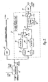
- a television camera comprises a focusing lens 1 which directs radiation from a scene to be imaged onto a beam splitter 2.
- the lens and beam splitter serve to focus the radiation onto two CCD imaging arrays, CCDA and CCDB, which are offset relative to one another by half a pixel horizontally and by one television line in the vertical direction.
- CCD imaging arrays CCDA and CCDB
- Figure 3 It is seen from Figure 3 that the CCD's used are of the type which do not have a dead band between adjacent horizontal elements and which have a spacing of less than one line width between adjacent rows of elements, thus; if super-imposed, there will be some degree of overlap as shown by the shading on Figure 3.
- the CCD's are of the three phase output types such as Philips three phase or Texas Instruments three phase devices.
- each respective CCD is fed to a respective one of two multiplexers 3a and 3b where they are combined to produce a respective single phase output signal which is fed to a respective one of two analogue-to-digital converters 4a and 4b.
- These are 6 bit converters and are arranged to sample at a frequency of 22.5 MHz, which is derived from a 45 MHz generator 5 and divide by two unit 6.
- the two 6-bit data lines from the respective A to D converters are combined by a two-to-one multiplexer 7 which is also fed from the 45 MHz generator 5. Since the frequency of the signals from the A to D converters was 135 Mb/sec then the output frequency from multiplexer 7 is 270 Mb/sec.
- Multiplexer 7 combines the odd TV lines from CCDA with the even lines of CCDB to produce a complete television picture (generally of 576 TV lines). In order to reduce the bandwidth it is convenient at this point to remove the normal line blanking period which is present on any television signal and generally comprises around 20% of the signal. This is achieved by a line blanking formatter 8 which serves to expand the active video information part of each line so as to encroach into the line blanking period.
- the rate of information emerging from the formatter is reduced, as each piece of information can be conceptually viewed as being a little further apart from its neighbours than before.
- the output rate from formatter 8 is 220 Mb/sec corresponding to a bandwidth of 18.3 MHz. It should be noted that it is also possible to remove the field blanking period and the signal may be reduced down to 203 Mb/sec which corresponds to a bandwidth of 17 MHz.
- the signal from the formatter is output in an 8-bit format where it can be applied directly to a digital recorder such as digital cassette recorder (DCR) 9.
- DCR digital cassette recorder
- Figure 2 shows apparatus suitable for replaying data from the digital recorder and converting it to a standard video format for TV display presentation.
- the signal from the digital recorder is output over an 8-bit line, at a rate which is one quarter of the rate it was input at ie. 55 Mb/sec to a line blanking formatter 10 which reintroduces the line blanking by compressing the data and hence increases the data rate to 67.5 Mb/sec in a 6-bit format.
- a line blanking formatter 10 which reintroduces the line blanking by compressing the data and hence increases the data rate to 67.5 Mb/sec in a 6-bit format.
- the filters are chosen to have a symmetrical cross-over characteristic, ie., 50% at 1 MHz and to be of low order form such as a single pole network.
- the low frequency portion separated out by filter 14 is fed through a single one television line period delay network 15.
- the high frequency portion from filter 13 is alternately fed by a switch 17 through a one line period delay 16 and a through line 18.
- the switch is arranged to actuate every other half pixel period (P/2). This process serves to double the number of pixels of the high frequency information.
- the low frequency information is all delayed by one line period so as to retain full vertical resolution of the system.
- the high frequency and low frequency signals are subsequently added together at 18 and passed through a half pixel delay 19 on alternate lines determined by a switch 20.
- CCDA is a colour stripped CCD with a spatial filter such as a Savart's plate and CCDB is a monochrome CCD.
- HDTV high definition television
- This approach is also useful for colour transmission by offsetting by 10% and 1 1/2 pixels (i.e. half the colour pitch of 3 pixels).
- the vertical inter-sensor spacing is as described above but, in order to achieve higher vertical resolution of more than 576 lines, interlace may need to be re-introduced and the cell structure changed.
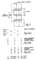
- Figure 5(a) illustrates how a CCD which has four imaging phases, such as Philips 4 phase 625 CCD sensors or certain types of 525 frame transfer devices, alternates its effective line position during a two field (2:1) interlace sequence between fields one and two.
- imaging phases such as Philips 4 phase 625 CCD sensors or certain types of 525 frame transfer devices
- Figure 5(b) shows how the outputs from the two CCD arrays A and B are interlaced over four fields. It is seen that there is still an overlap of CCD A and B on the same field and that both sensors shift their effective line position by 3.8 ⁇ m (For a conventional single sensor camera with normal interlace this would be 7.8 ⁇ m).
Abstract
A Television camera uses a pair of CCD imaging sensors (CCDA, CCDB), which are offset by half a pixel horizontally and one television line vertically and a beam splitter for focusing radiation from a scene to be imaged onto both imagers simultaneously. The outputs of the two imagers are digitised and combined at a compressed rate for recording on a digital cassette recorder (9). Signals may be read out from the cassette recorder at a quarter the rate they were input and subsequently processed (22) to obtain a higher resolution, high speed image of the non-interlaced kind. The invention may be applied in the field of high definition television.
Description
- This invention relates to video recording and reproducing apparatus and in particular it relates to a high resolution, high speed recording and reproducing apparatus which uses a solid state imaging sensor for the generation of television signals.
- The resolution and speeds required for television cameras are ever increasing. This can pose great problems for conventional technology and normally a trade-off is made between circuit complexity and resolution/speed. In particular, in conventional techniques problems are met when dealing with the very high bandwidth required and the difficulties of recording and displaying video signals at such high frequencies. The present invention arose in an effort to achieve such a high resolution, high speed system and also one in which interlacing is not required to achieve high resolution, although the invention is not limited to non-interlaced systems.
- According to the present invention there is provided video apparatus comprising a camera having a beam splitter for focusing radiation, from a scene to be imaged, simultaneously onto two solid state imagers, one imager being offset by half a pixel in one direction and one television line in an orthogonal direction, and means for combining the outputs from the two imagers to produce a single image of the scene.
- Preferably, the outputs from the imagers are digitised and compressed. Line blanking periods may be removed before the information is digitally stored in, for example, a digital cassette recorder.
- A reproduction means may be used in which information is read out from the recorder at a reduced rate which is preferably one quarter the rate at which it was input.
- In order to further increase resolution, the reproduction means may include means for delaying selected portions of selected frequency bands of the signal by selected amounts. This means preferably comprises means for delaying signals representative of alternate pixels of the information in a chosen high frequency band by one line period and means for delaying all information of frequency less than the high frequency band by one line period.
- The resulting information after appropriate delays can be combined and alternate lines delayed by half a pixel period.
- Embodiments of the invention will now be described, by way of example only, with reference to the accompanying drawings in which:
- Figure 1 shows schematically the elements of a video camera,
- Figure 2 shows a picture recovery apparatus for processing images recorded with the camera of Figure 1, and Figures 3, 4 and 5 are explanatory diagrams.
- Referring to Figure 1 a television camera comprises a focusing
lens 1 which directs radiation from a scene to be imaged onto abeam splitter 2. The lens and beam splitter serve to focus the radiation onto two CCD imaging arrays, CCDA and CCDB, which are offset relative to one another by half a pixel horizontally and by one television line in the vertical direction. This is shown in Figure 3. It is seen from Figure 3 that the CCD's used are of the type which do not have a dead band between adjacent horizontal elements and which have a spacing of less than one line width between adjacent rows of elements, thus; if super-imposed, there will be some degree of overlap as shown by the shading on Figure 3. The CCD's are of the three phase output types such as Philips three phase or Texas Instruments three phase devices. Since these are three phase devices then they can be scanned at one third the rate normally associated with a single phase output device and thus a higher overall scan rate can be achieved. The three outputs from each respective CCD are fed to a respective one of two multiplexers 3a and 3b where they are combined to produce a respective single phase output signal which is fed to a respective one of two analogue-to-digital converters 4a and 4b. These are 6 bit converters and are arranged to sample at a frequency of 22.5 MHz, which is derived from a 45MHz generator 5 and divide by twounit 6. - The two 6-bit data lines from the respective A to D converters are combined by a two-to-one multiplexer 7 which is also fed from the 45
MHz generator 5. Since the frequency of the signals from the A to D converters was 135 Mb/sec then the output frequency from multiplexer 7 is 270 Mb/sec. Multiplexer 7 combines the odd TV lines from CCDA with the even lines of CCDB to produce a complete television picture (generally of 576 TV lines). In order to reduce the bandwidth it is convenient at this point to remove the normal line blanking period which is present on any television signal and generally comprises around 20% of the signal. This is achieved by aline blanking formatter 8 which serves to expand the active video information part of each line so as to encroach into the line blanking period. Since the information is expanded it is clear that the rate of information emerging from the formatter is reduced, as each piece of information can be conceptually viewed as being a little further apart from its neighbours than before. Thus the output rate fromformatter 8 is 220 Mb/sec corresponding to a bandwidth of 18.3 MHz. It should be noted that it is also possible to remove the field blanking period and the signal may be reduced down to 203 Mb/sec which corresponds to a bandwidth of 17 MHz. The signal from the formatter is output in an 8-bit format where it can be applied directly to a digital recorder such as digital cassette recorder (DCR) 9. The dotted lines in Figure 1 show how if the output from both CCD sensors A and B were combined directly in the conventional manner then a video bandwidth of 30 MHz, corresponding to a bit rate of 360 Mb/sec would be produced since 360 Mb/sec is 6-bit quantised with a pixel clock of twotimes 30 MHz. Thus, the compression system of the present apparatus involves a reduction of 1.64:1 in bandwidth. - Figure 2 shows apparatus suitable for replaying data from the digital recorder and converting it to a standard video format for TV display presentation. The signal from the digital recorder is output over an 8-bit line, at a rate which is one quarter of the rate it was input at ie. 55 Mb/sec to a
line blanking formatter 10 which reintroduces the line blanking by compressing the data and hence increases the data rate to 67.5 Mb/sec in a 6-bit format. At this point it is possible to convert directly to analogue form by digital to analogue converter 11 and it may be useful to do this for test monitoring since a picture will be produced, but the picture will be of low resolution. This is shown as the 5 MHz signal at 12. - Referring briefly to Figures 3 and 4 it is seen that the image is spatially collected by the two CCD arrays A and B in the form shown in Figure 4a. The signal is actually recorded by the digital cassette recorder (DCR) in the form shown in Figure 4b. In order to achieve high resolution and high speed the signal is required to be output on the final television display in the form shown in Figure 4c. This is achieved by the
box 22 shown in dashed lines in Figure 2. In order to expand the resolution from the 2 x 4 version shown in Figure 4b to the 4 x 4 of Figure 4c, without degrading the vertical resolution, it is necessary to separate the signal into low and high frequency components. This is achieved by respective high pass and low pass filters 13 and 14 of Figure 2. The filters are chosen to have a symmetrical cross-over characteristic, ie., 50% at 1 MHz and to be of low order form such as a single pole network. The low frequency portion , separated out by filter 14 is fed through a single one television lineperiod delay network 15. Simultaneously, the high frequency portion from filter 13 is alternately fed by a switch 17 through a oneline period delay 16 and a throughline 18. The switch is arranged to actuate every other half pixel period (P/2). This process serves to double the number of pixels of the high frequency information. The low frequency information is all delayed by one line period so as to retain full vertical resolution of the system. The high frequency and low frequency signals are subsequently added together at 18 and passed through ahalf pixel delay 19 on alternate lines determined by aswitch 20. Thus thesignal lines 2, 4 etc. are delayed by half pixel periods. Digital-to-analogue conversion now takes place atconverter 21 and the final video wave form, now at 7.5 MHz is output to a TV display or perhaps to a conventional video recorder. The signal is in the form shown in Figure 4C which is shown to have high resolution in both the vertical and horizontal directions. A simple analysis of the system will reveal that the display is as shown in Figure 4C in which those symbols with a cross through them are those which have been generated by the one line period delay line and in which those pixels on alternate lines are delayed by half a pixel. - It is seen from the above that high vertical and horizontal resolution is achieved using a non-interlaced camera, ie. one in which a whole image is received during one frame. The prism used in Figure 1 enables a reduction of two-to-one to be made in the speed of the pixel clock since two sensors are read out in parallel. This also enables data and bandwidth compression to be achieved. Furthermore, the final image produced is not a synthetic representation but is an accurate representation of the image at higher resolution due to the fact that the frame transfer images used have overlapping pixels. It is preferable to use CCD sensors of the type which do not have dead bands between pixels, such as interline transfer devices.
- The system can be extended to produce a colour camera using only two CCD sensors. In one example CCDA is a colour stripped CCD with a spatial filter such as a Savart's plate and CCDB is a monochrome CCD.
- It is believed that high definition television (HDTV) standards favour a system which has twice the vertical and horizontal resolution of a conventional 625 or 525 systems and an aspect ratio of 5/3, compared to one of 4/3 for present day systems. This can be achieved using the techniques of the present invention by the use of two CCD sensors of 626 or 525 lines which are offset by 10% and half pixel to achieve the desired 5-3 aspect ratio. This approach is also useful for colour transmission by offsetting by 10% and 1 1/2 pixels (i.e. half the colour pitch of 3 pixels). The vertical inter-sensor spacing is as described above but, in order to achieve higher vertical resolution of more than 576 lines, interlace may need to be re-introduced and the cell structure changed.
- Figure 5(a) illustrates how a CCD which has four imaging phases, such as Philips 4 phase 625 CCD sensors or certain types of 525 frame transfer devices, alternates its effective line position during a two field (2:1) interlace sequence between fields one and two.
- When two sensors are used for HDTV the cell height has to be reduced from 11.6µm to 7.8µm. Figure 5(b) shows how the outputs from the two CCD arrays A and B are interlaced over four fields. It is seen that there is still an overlap of CCD A and B on the same field and that both sensors shift their effective line position by 3.8µm (For a conventional single sensor camera with normal interlace this would be 7.8µm).
- Such as arrangement yields a virtual resolution of 768 TV lines compared to 576 TV lines without interlace. (For a single sensor this would be 400 TV lines). A further extension of this principle involves a four field (4:1) interlace sequence and a consequential reduction of cell height to only 3.1µm.
Claims (11)
1. Video apparatus comprising a camera having a beam splitter for focusing radiation, from a scene to be imaged, simultaneously onto two solid state imagers, one imager being offset by half a pixel in one direction and one television line in an orthogonal direction, and means for combining the outputs from the two imagers to produce an image of the scene.
2. Video apparatus as claimed in Claim 1 and including an analogue-to-digital converter associated with each imager wherein the combining means comprises means for combining the outputs from the analogue-to-digital converters in a compressed manner.
3. Video apparatus as claimed in Claim 1 or Claim 2 further including means for removing at least a portion of the line and/or field blanking period of each line and/or field of data.
4. Video apparatus as claimed in any one of the preceding claims and including digital recording means for recording the image.
5. Video apparatus as claimed in Claim 4 further comprising reproduction means including means for reading data out of the recording means at a rate less than the rate at which it is input.
6. Apparatus as claimed in Claim 5 wherein the rate is one quarter of the input rate.
7. Apparatus as claimed in Claim 5 or Claim 6 wherein the reproduction means includes means for reinstating the line and/or field blanking period.
8. Apparatus as claimed in any of Claims 5 to 7 wherein the reproduction means includes means for delaying selected portions of selected frequency bands of the signal by selected amounts.
9. Apparatus as claimed in Claim 8 including means for delaying signals representative of alternate pixels of the information in a chosen high frequency band by one line period.
10. Apparatus as claimed in Claim 9 including means for delaying all information of frequency less than the high frequency band by one line period.
11. Apparatus as claimed in Claim 10 including means for combining the separated waveband information, after delaying if appropriate and for further delaying alternate lines of data by half a pixel period.
Applications Claiming Priority (2)
| Application Number | Priority Date | Filing Date | Title |
|---|---|---|---|
| GB8830098A GB2226469A (en) | 1988-12-23 | 1988-12-23 | Video recording and reproducing apparatus |
| GB8830098 | 1988-12-23 |
Publications (2)
| Publication Number | Publication Date |
|---|---|
| EP0375334A2 true EP0375334A2 (en) | 1990-06-27 |
| EP0375334A3 EP0375334A3 (en) | 1992-01-08 |
Family
ID=10649057
Family Applications (1)
| Application Number | Title | Priority Date | Filing Date |
|---|---|---|---|
| EP19890313237 Withdrawn EP0375334A3 (en) | 1988-12-23 | 1989-12-18 | Video recording and reproducing apparatus |
Country Status (4)
| Country | Link |
|---|---|
| US (1) | US5130814A (en) |
| EP (1) | EP0375334A3 (en) |
| JP (1) | JPH02276385A (en) |
| GB (1) | GB2226469A (en) |
Cited By (3)
| Publication number | Priority date | Publication date | Assignee | Title |
|---|---|---|---|---|
| NL9301907A (en) * | 1993-11-04 | 1995-06-01 | Paul Peter Hendrikus Schalkwij | Method for electronically storing radiation images |
| WO1996029821A2 (en) * | 1995-03-21 | 1996-09-26 | Philips Electronics N.V. | Image pick-up apparatus |
| EP1890475A1 (en) | 2006-08-15 | 2008-02-20 | STMicroelectronics (Research & Development) Limited | Video frame buffer |
Families Citing this family (15)
| Publication number | Priority date | Publication date | Assignee | Title |
|---|---|---|---|---|
| US5386228A (en) * | 1991-06-20 | 1995-01-31 | Canon Kabushiki Kaisha | Image pickup device including means for adjusting sensitivity of image pickup elements |
| DE4123791C2 (en) * | 1991-07-18 | 1995-10-26 | Daimler Benz Aerospace Ag | Digital area camera with multiple optics |
| KR950005050Y1 (en) * | 1991-12-05 | 1995-06-21 | 삼성전자 주식회사 | Analog circuit for disital camera |
| JPH08317295A (en) * | 1995-05-16 | 1996-11-29 | Olympus Optical Co Ltd | Digital image recording device and digital image reproducing device |
| EP0765086A2 (en) | 1995-09-21 | 1997-03-26 | AT&T Corp. | Video camera including multiple image sensors |
| US5926218A (en) * | 1996-06-04 | 1999-07-20 | Eastman Kodak Company | Electronic camera with dual resolution sensors |
| US6897895B1 (en) * | 1998-05-28 | 2005-05-24 | Sanyo Electric Co., Ltd. | Digital camera |
| JP2002335435A (en) * | 2001-05-11 | 2002-11-22 | Fujitsu Ltd | Vide photographing device |
| US7492390B2 (en) * | 2003-07-14 | 2009-02-17 | Arecont Vision, Llc. | Dual spectral band network camera |
| US20060055626A1 (en) * | 2004-09-16 | 2006-03-16 | Stephane Tremblay | Dual screen display using one digital data output |
| JP4742242B2 (en) * | 2005-09-30 | 2011-08-10 | カシオ計算機株式会社 | Imaging apparatus and program thereof |
| JP5172162B2 (en) * | 2006-08-25 | 2013-03-27 | 株式会社日立ハイテクノロジーズ | Defect inspection equipment |
| CN101681243A (en) * | 2007-03-26 | 2010-03-24 | 免费录制电视股份公司 | Video data transmission via usb interface |
| JP5003543B2 (en) * | 2008-03-17 | 2012-08-15 | ソニー株式会社 | Imaging apparatus, signal processing method, and computer program |
| US20110166968A1 (en) * | 2010-01-06 | 2011-07-07 | Richard Yin-Ching Houng | System and method for activating display device feature |
Citations (7)
| Publication number | Priority date | Publication date | Assignee | Title |
|---|---|---|---|---|
| US4263623A (en) * | 1979-04-02 | 1981-04-21 | Eastman Kodak Company | Slow-frame video camera/recorder and image-sensing and signal processing device for use therewith |
| JPS5724176A (en) * | 1980-07-21 | 1982-02-08 | Hitachi Ltd | Magnetic recording and playback device |
| EP0095725A1 (en) * | 1982-05-31 | 1983-12-07 | Kabushiki Kaisha Toshiba | Area sensor |
| JPS5936482A (en) * | 1982-08-25 | 1984-02-28 | Furoobell Eng Kk | Solid-state element camera |
| JPS59111484A (en) * | 1982-12-17 | 1984-06-27 | Sony Corp | Recorder of video signal |
| JPS6030285A (en) * | 1983-07-29 | 1985-02-15 | Victor Co Of Japan Ltd | Recording and reproducing device of video signal |
| JPS6042985A (en) * | 1983-08-19 | 1985-03-07 | Konishiroku Photo Ind Co Ltd | Video camera |
Family Cites Families (6)
| Publication number | Priority date | Publication date | Assignee | Title |
|---|---|---|---|---|
| JPS5654115B2 (en) * | 1974-03-29 | 1981-12-23 | ||
| GB2048609B (en) * | 1979-03-30 | 1983-05-25 | Hitachi Electronics | Solid-state colour imaging camera |
| US4438457A (en) * | 1981-07-20 | 1984-03-20 | Xerox Corporation | High resolution imager employing staggered sensor structure |
| US4432017A (en) * | 1981-07-20 | 1984-02-14 | Xerox Corporation | Adjacent bilinear photosite imager |
| US4765564A (en) * | 1985-04-02 | 1988-08-23 | The United States Of America As Represented By The Secretary Of The Interior | Solid state apparatus for imaging with improved resolution |
| FR2606242B1 (en) * | 1986-10-31 | 1989-02-24 | Thomson Csf | VIDEO MIXER CIRCUIT, USEFUL FOR HIGH RESOLUTION IMAGING WITH CAMERAS WITH SOLID MATRIX SENSORS |
-
1988
- 1988-12-23 GB GB8830098A patent/GB2226469A/en not_active Withdrawn
-
1989
- 1989-12-15 US US07/450,978 patent/US5130814A/en not_active Expired - Fee Related
- 1989-12-18 EP EP19890313237 patent/EP0375334A3/en not_active Withdrawn
- 1989-12-25 JP JP1336197A patent/JPH02276385A/en active Pending
Patent Citations (7)
| Publication number | Priority date | Publication date | Assignee | Title |
|---|---|---|---|---|
| US4263623A (en) * | 1979-04-02 | 1981-04-21 | Eastman Kodak Company | Slow-frame video camera/recorder and image-sensing and signal processing device for use therewith |
| JPS5724176A (en) * | 1980-07-21 | 1982-02-08 | Hitachi Ltd | Magnetic recording and playback device |
| EP0095725A1 (en) * | 1982-05-31 | 1983-12-07 | Kabushiki Kaisha Toshiba | Area sensor |
| JPS5936482A (en) * | 1982-08-25 | 1984-02-28 | Furoobell Eng Kk | Solid-state element camera |
| JPS59111484A (en) * | 1982-12-17 | 1984-06-27 | Sony Corp | Recorder of video signal |
| JPS6030285A (en) * | 1983-07-29 | 1985-02-15 | Victor Co Of Japan Ltd | Recording and reproducing device of video signal |
| JPS6042985A (en) * | 1983-08-19 | 1985-03-07 | Konishiroku Photo Ind Co Ltd | Video camera |
Non-Patent Citations (5)
| Title |
|---|
| PATENT ABSTRACTS OF JAPAN vol. 6, no. 91 (E-109) 28 May 1982, & JP-A-57 024176 (HITACHI) 08 February 1982, * |
| PATENT ABSTRACTS OF JAPAN vol. 8, no. 123 (E-249) 08 June 1984, & JP-A-59 036482 (FUROOBERU ENGINEERING) 28 February 1984, * |
| PATENT ABSTRACTS OF JAPAN vol. 8, no. 231 (E-274) 24 October 1984, & JP-A-59 111484 (SONY) 27 June 1984, * |
| PATENT ABSTRACTS OF JAPAN vol. 9, no. 150 (E-324) 25 June 1985, & JP-A-60 030285 (NIPPON VICTOR) 15 February 1985, * |
| PATENT ABSTRACTS OF JAPAN vol. 9, no. 169 (E-328) 13 July 1985, & JP-A-60 042985 (KONISHIROKU SHASHIN KOGYO) 07 March 1985, * |
Cited By (6)
| Publication number | Priority date | Publication date | Assignee | Title |
|---|---|---|---|---|
| NL9301907A (en) * | 1993-11-04 | 1995-06-01 | Paul Peter Hendrikus Schalkwij | Method for electronically storing radiation images |
| WO1996029821A2 (en) * | 1995-03-21 | 1996-09-26 | Philips Electronics N.V. | Image pick-up apparatus |
| WO1996029821A3 (en) * | 1995-03-21 | 1996-12-05 | Philips Electronics Nv | Image pick-up apparatus |
| US5774269A (en) * | 1995-03-21 | 1998-06-30 | U.S. Philips Corporation | Image pick-up apparatus |
| EP1890475A1 (en) | 2006-08-15 | 2008-02-20 | STMicroelectronics (Research & Development) Limited | Video frame buffer |
| US8922676B2 (en) | 2006-08-15 | 2014-12-30 | Stmicroelectronics (Research & Development) Limited | Video frame buffer |
Also Published As
| Publication number | Publication date |
|---|---|
| EP0375334A3 (en) | 1992-01-08 |
| GB2226469A (en) | 1990-06-27 |
| US5130814A (en) | 1992-07-14 |
| JPH02276385A (en) | 1990-11-13 |
Similar Documents
| Publication | Publication Date | Title |
|---|---|---|
| US5130814A (en) | Video recording and reproducing apparatus including dual offset ccd image arrays | |
| DE69634463T2 (en) | Image pickup device with progressive or non-interlaced scanning image pickup device | |
| US5657082A (en) | Imaging apparatus and method using interpolation processing | |
| US5621470A (en) | Interpixel and interframe interpolation of television pictures with conversion from interlaced to progressive scanning | |
| JP2936760B2 (en) | Color television camera device | |
| JPH0147073B2 (en) | ||
| EP0187406B1 (en) | High resolution television transmission system | |
| EP1763224B1 (en) | Video signal processing in a camera control unit | |
| HUT63528A (en) | Method, coder and decoder for transmitting and compatible receiving standardized television signals | |
| US6134347A (en) | Image filming and compression system, image filming and compression method, and recording medium storing processing program therefor | |
| JP2797393B2 (en) | Recording and playback device | |
| EP0270269A2 (en) | Image scanning system | |
| JP3648638B2 (en) | Color imaging device | |
| EP0792067A2 (en) | Vertical line multiplication method for high-resolution camera and circuit therefor | |
| CA2077212A1 (en) | Television camera | |
| JPH052033B2 (en) | ||
| US4772949A (en) | High resolution television transmission system | |
| KR100222971B1 (en) | Apparatus for high definition image scanner using 3 sensor | |
| JP3728075B2 (en) | Imaging method and imaging apparatus | |
| US3823260A (en) | Colour television camera | |
| KR100562595B1 (en) | Image apparatus | |
| JP2594596B2 (en) | Image signal transmission method | |
| JPS63123286A (en) | Electronic still camera | |
| JP4515546B2 (en) | Image signal processing apparatus and electronic still camera equipped with the apparatus | |
| JPH0328112B2 (en) |
Legal Events
| Date | Code | Title | Description |
|---|---|---|---|
| PUAI | Public reference made under article 153(3) epc to a published international application that has entered the european phase |
Free format text: ORIGINAL CODE: 0009012 |
|
| AK | Designated contracting states |
Kind code of ref document: A2 Designated state(s): DE FR NL |
|
| PUAL | Search report despatched |
Free format text: ORIGINAL CODE: 0009013 |
|
| AK | Designated contracting states |
Kind code of ref document: A3 Designated state(s): DE FR NL |
|
| STAA | Information on the status of an ep patent application or granted ep patent |
Free format text: STATUS: THE APPLICATION IS DEEMED TO BE WITHDRAWN |
|
| 18D | Application deemed to be withdrawn |
Effective date: 19920703 |