EP0368710A1 - Devices for discriminating between a number of simultaneous phenomena - Google Patents
Devices for discriminating between a number of simultaneous phenomena Download PDFInfo
- Publication number
- EP0368710A1 EP0368710A1 EP89402890A EP89402890A EP0368710A1 EP 0368710 A1 EP0368710 A1 EP 0368710A1 EP 89402890 A EP89402890 A EP 89402890A EP 89402890 A EP89402890 A EP 89402890A EP 0368710 A1 EP0368710 A1 EP 0368710A1
- Authority
- EP
- European Patent Office
- Prior art keywords
- circuit
- delay
- transmitter
- signals
- duration
- Prior art date
- Legal status (The legal status is an assumption and is not a legal conclusion. Google has not performed a legal analysis and makes no representation as to the accuracy of the status listed.)
- Ceased
Links
Images
Classifications
-
- G—PHYSICS
- G08—SIGNALLING
- G08B—SIGNALLING OR CALLING SYSTEMS; ORDER TELEGRAPHS; ALARM SYSTEMS
- G08B29/00—Checking or monitoring of signalling or alarm systems; Prevention or correction of operating errors, e.g. preventing unauthorised operation
- G08B29/18—Prevention or correction of operating errors
- G08B29/185—Signal analysis techniques for reducing or preventing false alarms or for enhancing the reliability of the system
-
- G—PHYSICS
- G08—SIGNALLING
- G08B—SIGNALLING OR CALLING SYSTEMS; ORDER TELEGRAPHS; ALARM SYSTEMS
- G08B25/00—Alarm systems in which the location of the alarm condition is signalled to a central station, e.g. fire or police telegraphic systems
- G08B25/01—Alarm systems in which the location of the alarm condition is signalled to a central station, e.g. fire or police telegraphic systems characterised by the transmission medium
- G08B25/10—Alarm systems in which the location of the alarm condition is signalled to a central station, e.g. fire or police telegraphic systems characterised by the transmission medium using wireless transmission systems
Landscapes
- Engineering & Computer Science (AREA)
- Physics & Mathematics (AREA)
- General Physics & Mathematics (AREA)
- Computer Security & Cryptography (AREA)
- Computer Networks & Wireless Communication (AREA)
- Business, Economics & Management (AREA)
- Emergency Management (AREA)
- Alarm Systems (AREA)
- Burglar Alarm Systems (AREA)
Abstract
Description
L'invention concerne les dispositifs pour permettre de discriminer plusieurs phénomènes qui se produisent simultanément; elle concerne plus particulièrement les systèmes de sécurité dans lesquels les informations des capteurs ou détecteurs de dangers sont transmises vers un récepteur unique et peuvent donc être reçues simultanément.The invention relates to devices for discriminating between several phenomena which occur simultaneously; it relates more particularly to security systems in which the information from the danger sensors or detectors is transmitted to a single receiver and can therefore be received simultaneously.
Dans les systèmes de sécurité, les dispositifs qui détectent des événements tels que des effractions, des vols, des feux, des gaz sont indépendants les uns des autres mais ils sont connectés par des liaisons filaires ou radioélectriques à un récepteur unique. Plus le nombre de détecteurs est grand, plus la probabilité pour que deux ou plusieurs événements se produisent simultanément est grande. Or, si deux ou plusieurs événements se produisent simultanément, il y a risque de cumul, de distorsion, de perturbation ou de conflit entre les signaux reçus par le récepteur, ce qui entraîne soit la perte d'informations, soit la génération de signaux erronés.In security systems, the devices which detect events such as break-ins, thefts, fires, gases are independent of each other but they are connected by wire or radio links to a single receiver. The greater the number of detectors, the greater the probability that two or more events will occur simultaneously. However, if two or more events occur simultaneously, there is a risk of accumulation, distortion, disturbance or conflict between the signals received by the receiver, which leads to either the loss of information or the generation of erroneous signals .
Le but de la présente invention est donc de réaliser un dispositif pour permettre de discriminer plusieurs phénomènes simultanés, notamment dans un système de sécurité comportant N détecteurs/émetteurs associés à un récepteur unique.The object of the present invention is therefore to provide a device for discriminating several simultaneous phenomena, in particular in a security system comprising N detectors / transmitters associated with a single receiver.
L'invention se rapporte à un dispositif pour permettre de discriminer entre plusieurs phénomènes simultanés dans un système de sécurité qui comporte une pluralité d'émetteurs (nombre N) et un récepteur unique dans lequel chaque émetteur comprend un circuit de mise en forme d'un signal représentatif du phénomène détecté et un circuit de transmission dudit signal représentatif, caractérisé en ce que chaque émetteur comprend en outre un circuit à retards de durées variables disposé entre le circuit de mise en forme et le circuit de transmission et un circuit de commande dudit circuit à retards variables, prévus de manière à retarder ledit signal représentatif d'une durée qui est différente d'un émetteur à l'autre.The invention relates to a device for discriminating between several simultaneous phenomena in a security system which comprises a plurality of transmitters (number N) and a single receiver in which each transmitter comprises an activation circuit. form of a signal representative of the phenomenon detected and a circuit for transmitting said representative signal, characterized in that each transmitter further comprises a delay circuit of variable durations disposed between the shaping circuit and the transmission circuit and a circuit for controlling said variable delay circuit, provided so as to delay said signal representative of a duration which is different from one transmitter to another.
Pour augmenter la sécurité de transmission de phénomènes simultanés, chaque émetteur comprend en outre une liaison directe entre le circuit de mise en forme et le circuit de transmission de manière à transmettre d'abord le signal représentatif dès l'apparition dudit phénomène.To increase the security of transmission of simultaneous phenomena, each transmitter further comprises a direct link between the shaping circuit and the transmission circuit so as to first transmit the representative signal as soon as said phenomenon appears.
D'autres caractéristiques et avantages de la présente invention apparaîtront à la lecture de la description suivante d'un exemple particulier de réalisation, ladite description étant faite en relation avec le dessin joint dans lequel :
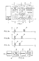
- - la figure 1 est un schéma fonctionnel d'un détecteur émetteur d'un système de sécurité, l'émetteur étant réalisé conformément à l'invention,
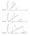
- - les figures 2-a, 2-b et 2-c sont des diagrammes temporels donnant une représentation des retards qui peuvent être obtenus en cas de trois événements simultanés,
- - les figures 3-a, 3-b, 3-c et 3-d sont des diagrammes temporels donnant les instants d'émission des trains impulsions émis correspondant à trois phénomènes simultanés, et
- - la figure 4 est un schéma fonctionnel d'un récepteur selon la présente invention,
- FIG. 1 is a functional diagram of a detector transmitter of a security system, the transmitter being produced in accordance with the invention,
- - the figures 2-a, 2-b and 2-c are time diagrams giving a representation of the delays which can be obtained in the event of three simultaneous events,
- FIGS. 3-a, 3-b, 3-c and 3-d are time diagrams giving the instants of emission of the pulse trains emitted corresponding to three simultaneous phenomena, and
- FIG. 4 is a functional diagram of a receiver according to the present invention,
L'invention sera décrite dans son application à un système de sécurité qui comprend un nombre N de détecteurs/émetteurs, chaque détecteur/émetteur comprenant un dispositif de détection des alarmes 1 et un émetteur 2. Les N détecteurs/émetteurs sont indépendants les uns des autres et sont connectés à un récepteur unique par des liaisons filaires ou radioélectriques. Le nombre N peut varier de quelques dizaines à quelques milliers. Bien entendu, le dispositif de l'invention est particulièrement intéressant lorsque le nombre N est grand car la probabilité pour que plusieurs événements ou alarmes se produisent simultanément, y compris les alarmes intempestives, est également grande.The invention will be described in its application to a security system which comprises a number N of detectors / transmitters, each detector / transmitter comprising an
Selon l'invention, il est proposé soit de retarder systématiquement la transmission du signal du capteur d'une durée variable pour chaque capteur, soit de transmettre systématiquement deux signaux, l'un en temps réel et l'autre retardé d'une durée variable pour chaque capteur.According to the invention, it is proposed either to systematically delay the transmission of the signal from the sensor by a variable duration for each sensor, or to systematically transmit two signals, one in real time and the other delayed by a variable duration for each sensor.
Pour réaliser un tel retard variable dans chaque émetteur, l'invention propose un émetteur dont le schéma fonctionnel est donné par la figure 1. Sur cette figure 1, le détecteur 1 est associé à l'émetteur 2 et lui fournit un signal d'alarme lorsqu'il détecte un danger : effraction, vol, fumée, gaz etc...To achieve such a variable delay in each transmitter, the invention proposes a transmitter whose functional diagram is given in FIG. 1. In this FIG. 1, the
L'émetteur 2 comprend un circuit de mise en forme 3 du signal reçu du détecteur 1 de manière à le présenter sous une forme appropriée, celle prévue pour le système de sécurité, pour qu'il soit identifiable par le récepteur unique du système de sécurité. Il s'agit d'un signal codé qui contient un certain nombre d'informations tel que l'identification du détecteur/émetteur et le type d'alarme. Le signal codé est appliqué à un circuit de retard 4 dont le retard est variable selon des critères qui seront expliqués ci-après. Le signal retardé est appliqué à un circuit de transmission 5 qui le met sous la forme requise pour être transmis sur une liaison filaire ou une liaison radioélectrique.The
Chaque émetteur comprend aussi un circuit horloge 6 qui donne des signaux à une fréquence déterminée, la même d'un émetteur à l'autre dans un système de sécurité déterminé. Les signaux élaborés par le circuit horloge 6 sont appliqués à un circuit de base de temps 7 dont les signaux de sortie commandent le circuit de retards 4 de manière à obtenir un retard variable en fonction du code d'identification de l'émetteur contenu dans une mémoire 8.Each transmitter also includes a
Comme le circuit de retards 4 est identique d'un émetteur à l'autre, on obtient le retard variable en commandant le circuit de retards par des signaux de fréquence variable. La variation de la fréquence est obtenue en utilisant l'information du code d'identification de l'émetteur qui est différente d'un émetteur à l'autre.As the
De manière plus précise, on supposera que le circuit de retards 4 est prévu pour fournir huit retards différents dont chacun est un multiple entier jusque huit d'un retard élémentaire ϑ.More precisely, it will be assumed that the
Le circuit de base de temps 7 comprend par exemple un circuit diviseur 9 qui divise la fréquence du signal horloge par un facteur que l'on prendra égal au code d'identification, facteur qui pourra varier de 1 à 4096 s'il y a 4096 émetteurs dans le système de sécurité. Les signaux fournis par le circuit diviseur 9, qui ont donc une fréquence qui est significative de l'émetteur concerné, sont appliqués à un compteur/décodeur 10. Les huit sorties du compteur/décodeur 10 sont connectés au circuit de retards 4 de manière à effectuer le choix d'un temps de retard parmi les huit possibles.The
Le circuit de mise en forme 3 fournit un signal sur le conducteur 11 dès qu'il reçoit un signal d'alarme; ce signal sert à arrêter le compteur/décodeur 10 pour que la ligne à retard 4 reste sur une position de retard déterminé.The
Les figures 2-a, 2-b et 2-c représentent des diagrammes qui permettent de comprendre l'obtention d'un retard parmi huit retards différents. La courbe en escalier 22, 23 ou 24 représente en fonction du temps les retards obtenus, chaque palier correspondant à une position de décodage et donc à un retard déterminé. Comme les signaux qui sont appliqués au compteur/décodeur 10 (figure 1) ont une fréquence différente d'un émetteur à l'autre, la durée de chaque palier est aussi différente et il en est de même de celle du cycle complet. Sur la figure 2, seul un cycle complet a été représenté pour chaque émetteur plus le début du cycle suivant.Figures 2-a, 2-b and 2-c represent diagrams which make it possible to include / understand the obtaining of a delay among eight different delays. The
Pour la clarté de l'exposé, le diagramme de la figure 2-a correspond à un émetteur E₁ (code d'identification 1), celui de la figure 2-b à un émetteur Ei (code d'identification i) et celui de la figure 2-c à un émetteur EN (code d'identification N - le dernier du système). Si l'on suppose que trois événements arrivent simultanément au temps tx dans chacun des émetteurs E₁, Ei et EN, ce temps tx correspond au quatrième palier pour E₁, au troisième palier pour Ei et au deuxième palier pour EN. En conséquence, dans E₁, le retard sera de 4 ϑ; dans Ei, le retard sera de 3 ϑ; dans EN le retard sera de 2 ϑ.For the sake of clarity, the diagram of figure 2-a corresponds to a transmitter E₁ (identification code 1), that of figure 2-b to a transmitter E i (identification code i) and that of the figure 2-c to a transmitter E N (identification code N - the last of the system). If we assume that three events occur simultaneously at time t x in each of the emitters E₁, E i and E N , this time t x corresponds to the fourth level for E₁, to the third level for E i and to the second level for E N . Consequently, in E₁, the delay will be 4 ϑ; in E i , the delay will be 3 ϑ; in E N the delay will be 2 ϑ.
Le fonctionnement du détecteur/émetteur de la figure 1 qui vient d'être décrit montre que les signaux d'alarme de trois événements simultanés sont transmis à trois instants différents. Les diagrammes des figures 3-a, 3-b et 3-c montrent les impulsions 25, 26 et 27 des émetteurs E₁, Ei et EN dans le cas décrit en relation avec la figure 2. On remarquera que les signaux E₁, Ei et EN sont des signaux codés et peuvent se présenter chacun sous la forme d'un train d'impulsions.The operation of the detector / transmitter of FIG. 1 which has just been described shows that the alarm signals of three simultaneous events are transmitted to three different moments. The diagrams of figures 3-a, 3-b and 3-c show the
Le retard élémentaire ϑ doit être supérieur au temps de discrimination du récepteur. En effet, pendant cette durée ϑ, des événements peuvent se produire dans l'un quelconque des détecteurs/émetteurs et il faut donc que les retards qui leur seront appliqués soient supérieurs à ϑ pour que les signaux reçus par le récepteur puissent être discriminés. Par ailleurs, les différents événements apparaissant pendant la durée ϑ, doivent donner lieu à un retard différent à l'émission, ce qui signifie que la durée de retard qui est sélectionnée doit être différente d'un émetteur à l'autre. Pour qu'il en soit ainsi, il faut que, dans chaque émetteur, les différentes durées de retard soient sélectionnées en un temps inférieur à ϑ, ce qui signifie que la fréquence des signaux fournis par le circuit diviseur 9 doit être choisie en conséquence. Sur les figures 2-a, 2-b et 2-c, cela signifie que la durée des courbes en escalier 22, 23 et 24 doit être inférieure à ϑ.The elementary delay ϑ must be greater than the discrimination time of the receiver. Indeed, during this time ϑ, events can occur in any one of the detectors / transmitters and it is therefore necessary that the delays which will be applied to them be greater than ϑ so that the signals received by the receiver can be discriminated. Furthermore, the various events appearing during the duration ϑ must give rise to a different delay in transmission, which means that the delay duration which is selected must be different from one transmitter to another. For this to be so, it is necessary that, in each transmitter, the different delay times are selected in a time of less than ϑ, which means that the frequency of the signals supplied by the divider circuit 9 must be chosen accordingly. On the figures 2-a, 2-b and 2-c, that means that the duration of the curves in
Le dispositif de la figure 1, tel que décrit ci-dessus, c'est-à-dire sans la liaison 20 entre le circuit de mise en forme 3 et le circuit de transmission 5, est satisfaisant dans de nombreux systèmes de sécurité. Cependant, on comprend que la probabilité pour avoir un même retard sur deux émetteurs est d'autant plus grande que le nombre de retards possibles est petit et que le nombre d'émetteurs est grand. Il en résulte que pour des systèmes de sécurité ayant un nombre N très grand, on est amené à avoir un nombre p de retards différents également grand, ce qui n'est pas toujours possible à réaliser. En outre, cela implique une fréquence des signaux de comptage également grande car les p retards doivent pouvoir être sélectionnés pendant la durée ϑ.The device of FIG. 1, as described above, that is to say without the
Enfin, comme les signaux des différents circuits horloge 6 ne sont pas en général en phase, il peut arriver qu'un instant tx (figure 2) d'apparition d'événements simultanés corresponde à un même palier sur plusieurs courbes en escalier et donc à un même retard.Finally, as the signals of the
En outre, il peut se produire que deux événements ou plus qui surviennent à des instants différents donnent lieu à des impulsions d'émission qui sont simultanées car les temps de retard qui sont introduits par le dispositif sont différents.In addition, it can happen that two or more events which occur at different times give rise to transmission pulses which are simultaneous because the delay times which are introduced by the device are different.
Dans ces conditions, il est proposé selon l'invention de doubler l'émission du signal dès qu'un événement survient. A cet effet, le dispositif de la figure 1 est modifié par l'addition de la liaison 20 mentionnée ci-dessus entre le circuit de mise en forme 3 et le circuit de transmission 5. Cette liaison 20 permet de commander le circuit 5 pour qu'il émette une première impulsion ou train d'impulsions dès l'apparition de l'événement, cette première impulsion étant suivie d'une deuxième impulsion qui est retardée par la ligne à retard 4 dans les mêmes conditions que ce qui a été décrit précédemment.Under these conditions, it is proposed according to the invention to double the emission of the signal as soon as an event occurs. To this end, the device of FIG. 1 is modified by the addition of the
En conséquence, le récepteur unique recevra pour chaque émetteur deux impulsions et ne tiendra donc compte que de la première impulsion reçue référencée 28 sur la figure 3-a. Lorsque plusieurs événements ont lieu simultanément, par exemple trois, le récepteur recevra d'abord simultanément trois impulsions qu'il ne pourra pas discriminer, ce sont les impulsions 28, 29 et 30 de la figure 3. Il recevra ensuite les impulsions 25, 26 et 27 qui sont décalées dans le temps et qui peuvent donc être discriminées.Consequently, the single receiver will receive for each transmitter two pulses and will thus only take account of the first pulse received referenced 28 on the figure 3-a. When several events take place simultaneously, for example three, the receiver will first receive simultaneously three pulses which it will not be able to discriminate, these are the
Si des évènements se produisaient de telle sorte que les trains d'impulsions 25, 26 et 27 seraient simultanés, on comprend que le récepteur discriminerait les trains d'impulsions 28, 29 et 30 qui eux ne seraient pas simultanés.If events occur such that the pulse trains 25, 26 and 27 are simultaneous, it is understood that the receiver would discriminate between the pulse trains 28, 29 and 30 which are not simultaneous.
Il est à remarquer qu'en fonctionnement normal, c'est-à-dire en l'absence d'événements simultanés, le récepteur reçoit deux impulsions successives qu'il peut discriminer. Il peut tenir compte de la deuxième impulsion pour valider la première, ce qui renforce la sécurité.It should be noted that in normal operation, that is to say in the absence of simultaneous events, the receiver receives two successive pulses which it can discriminate. It can take the second impulse into account to validate the first, which increases security.
Dans les deux dispositifs de l'invention qui viennent d'être décrits, le récepteur qui est utilisé est du type classique mais il doit comporter des circuits logiques complémentaires selon le dispositif choisi, circuits complémentaires qui sont à la portée de l'homme de métier.In the two devices of the invention which have just been described, the receiver which is used is of the conventional type but it must include complementary logic circuits according to the chosen device, complementary circuits which are within the reach of the skilled person. .
On rappellera seulement, en relation avec la figure 4, les éléments principaux d'un récepteur unique d'un système de sécurité. Il comprend un circuit de réception 35 qui reçoit et détecte les signaux émis par les détecteurs/émetteurs. Ce circuit de réception 35 est connecté à un circuit de mise en forme 36 dont les signaux de sortie sont appliqués à un décodeur 37. Les signaux logiques fournis par le décodeur 37 sont appliqués à un circuit logique 38. A ce stade de la description, un tel récepteur correspond à des détecteurs/émetteurs fonctionnant selon le premier dispositif (figure 1).We will only recall, in relation to FIG. 4, the main elements of a single receiver of a security system. It comprises a reception circuit 35 which receives and detects the signals transmitted by the detectors / transmitters. This reception circuit 35 is connected to a
Avec des détecteurs/émetteurs fonctionnant selon le deuxième dispositif, le récepteur doit être complété par une liaison 39 entre le circuit de réception 35 et le circuit logique 38, cette liaison servant à fournir un signal qui indique que plusieurs impulsions sont reçus simultanément. Dans ce cas, le circuit logique 38 doit être modifié pour inclure des circuits complémentaires pour que le récepteur ne tienne pas compte des premières impulsions reçues.With detectors / transmitters operating according to the second device, the receiver must be completed by a
Par ailleurs, cette liaison 39 peut aussi être utilisée pour valider le premier train d'impulsions reçu par le deuxième comme on l'a indiqué ci-dessus.Furthermore, this
Claims (5)
Applications Claiming Priority (2)
| Application Number | Priority Date | Filing Date | Title |
|---|---|---|---|
| FR8813921 | 1988-10-25 | ||
| FR8813921A FR2638268B1 (en) | 1988-10-25 | 1988-10-25 | DEVICES FOR ALLOWING DISCRIMINATION BETWEEN SEVERAL SIMULTANEOUS PHENOMENAS |
Publications (1)
| Publication Number | Publication Date |
|---|---|
| EP0368710A1 true EP0368710A1 (en) | 1990-05-16 |
Family
ID=9371249
Family Applications (1)
| Application Number | Title | Priority Date | Filing Date |
|---|---|---|---|
| EP89402890A Ceased EP0368710A1 (en) | 1988-10-25 | 1989-10-19 | Devices for discriminating between a number of simultaneous phenomena |
Country Status (2)
| Country | Link |
|---|---|
| EP (1) | EP0368710A1 (en) |
| FR (1) | FR2638268B1 (en) |
Cited By (4)
| Publication number | Priority date | Publication date | Assignee | Title |
|---|---|---|---|---|
| EP0446979A1 (en) * | 1990-03-16 | 1991-09-18 | Ericsson Radio Systems B.V. | System for transmitting alarm signals with a repetition |
| EP0607562A1 (en) * | 1992-12-18 | 1994-07-27 | GRUNDIG E.M.V. Elektro-Mechanische Versuchsanstalt Max Grundig GmbH & Co. KG | Radio alarm system with asynchronous transmission of messages on time channels of differing periods |
| FR2748340A1 (en) * | 1996-05-02 | 1997-11-07 | Dumberger Electro Bobinage Ets | Alarm surveillance system for e.g. car, house, or hotel room |
| EP1204954A1 (en) * | 1999-08-16 | 2002-05-15 | Checkpoint Systems, Inc. | Electronic article security system employing variable time shifts |
Citations (4)
| Publication number | Priority date | Publication date | Assignee | Title |
|---|---|---|---|---|
| US3665312A (en) * | 1969-10-06 | 1972-05-23 | Goldman Paul | Radio alarm system |
| DE2351013A1 (en) * | 1973-10-11 | 1975-04-17 | Licentia Gmbh | Signal blocks transmission method - between several stations operating on same channel involves asynchronous staggering in time |
| FR2415406A1 (en) * | 1978-01-18 | 1979-08-17 | Compur Electronic Gmbh | METHOD AND DEVICE FOR THE TRANSMISSION OF INFORMATION BETWEEN SEVERAL TRANSMITTERS AND A RECEIVER, IN PARTICULAR IN A PERSONAL PROTECTION INSTALLATION |
| GB2186404A (en) * | 1986-02-06 | 1987-08-12 | Notifier Co | Security system with signal accuracy checking |
-
1988
- 1988-10-25 FR FR8813921A patent/FR2638268B1/en not_active Expired - Fee Related
-
1989
- 1989-10-19 EP EP89402890A patent/EP0368710A1/en not_active Ceased
Patent Citations (4)
| Publication number | Priority date | Publication date | Assignee | Title |
|---|---|---|---|---|
| US3665312A (en) * | 1969-10-06 | 1972-05-23 | Goldman Paul | Radio alarm system |
| DE2351013A1 (en) * | 1973-10-11 | 1975-04-17 | Licentia Gmbh | Signal blocks transmission method - between several stations operating on same channel involves asynchronous staggering in time |
| FR2415406A1 (en) * | 1978-01-18 | 1979-08-17 | Compur Electronic Gmbh | METHOD AND DEVICE FOR THE TRANSMISSION OF INFORMATION BETWEEN SEVERAL TRANSMITTERS AND A RECEIVER, IN PARTICULAR IN A PERSONAL PROTECTION INSTALLATION |
| GB2186404A (en) * | 1986-02-06 | 1987-08-12 | Notifier Co | Security system with signal accuracy checking |
Cited By (7)
| Publication number | Priority date | Publication date | Assignee | Title |
|---|---|---|---|---|
| EP0446979A1 (en) * | 1990-03-16 | 1991-09-18 | Ericsson Radio Systems B.V. | System for transmitting alarm signals with a repetition |
| US5164704A (en) * | 1990-03-16 | 1992-11-17 | Ericsson Radio Systems B.V. | System for transmitting alarm signals with a repetition |
| EP0607562A1 (en) * | 1992-12-18 | 1994-07-27 | GRUNDIG E.M.V. Elektro-Mechanische Versuchsanstalt Max Grundig GmbH & Co. KG | Radio alarm system with asynchronous transmission of messages on time channels of differing periods |
| FR2748340A1 (en) * | 1996-05-02 | 1997-11-07 | Dumberger Electro Bobinage Ets | Alarm surveillance system for e.g. car, house, or hotel room |
| EP1204954A1 (en) * | 1999-08-16 | 2002-05-15 | Checkpoint Systems, Inc. | Electronic article security system employing variable time shifts |
| JP2003507801A (en) * | 1999-08-16 | 2003-02-25 | チエツクポイント システムズ, インコーポレーテツド | Electronic article security system using variable time shift |
| EP1204954A4 (en) * | 1999-08-16 | 2005-01-12 | Checkpoint Systems Inc | Electronic article security system employing variable time shifts |
Also Published As
| Publication number | Publication date |
|---|---|
| FR2638268B1 (en) | 1994-02-11 |
| FR2638268A1 (en) | 1990-04-27 |
Similar Documents
| Publication | Publication Date | Title |
|---|---|---|
| FR2522829A1 (en) | DEVICE FOR DETECTING THE PASSAGE OF LABELS NEAR A CONTROL STATION | |
| FR2536781A1 (en) | CENTRAL LOCKING INSTALLATION FOR A MOTOR VEHICLE | |
| FR2526980A1 (en) | TEMPORAL MULTIPLEX REMOTE CONTROL SYSTEM | |
| EP0094279B1 (en) | Method of protecting a telemonitoring system against sabotage and system carrying out this method | |
| FR2589564A1 (en) | MINE WITH WAKE-UP AND TRIGGER SENSORS | |
| FR2574948A1 (en) | AMI-ENEMY INTERROGATION METHOD AND SYSTEM USING THE SAME | |
| EP0897563A1 (en) | Method for selecting an electronic module from a plurality of modules present in the query field of a terminal | |
| FR2537308A1 (en) | METHOD AND DEVICE FOR TRANSMITTING INFORMATION | |
| EP0368710A1 (en) | Devices for discriminating between a number of simultaneous phenomena | |
| FR2707394A1 (en) | Element and photosensitive detector for the detection of flashes. | |
| JPH11160432A (en) | Optical pulse radar and optical pulse receiver | |
| FR2724746A1 (en) | DEVICE AND METHOD FOR REMOTE CONTROL OF AN OBJECT | |
| EP0199294B1 (en) | Method and device for signalling over a bidirectional digital transmission link | |
| EP0112429B1 (en) | System for the transmission of data by repetitive sequences | |
| EP0193453B1 (en) | Device for controlling a pulse period | |
| FR2483104A1 (en) | ALARM ZONE INDICATOR DEVICE | |
| EP0726666B1 (en) | Interface circuit between communication media in a home network | |
| EP1348204A1 (en) | System for detecting individuals or objects passing through an entrance-exit of a defined space | |
| EP0312431B1 (en) | Remote goods and/or persons supervising method | |
| EP0125624B1 (en) | Device for the electromagnetic transmission of an event in a disturbed environment | |
| EP0028188A1 (en) | Beacon system for stage-by-stage transmission of information | |
| EP0184107A1 (en) | Method for signalling over a digital transmission link and arrangement for carrying out the method | |
| EP0184108A1 (en) | Method and arrangement for signalling over a digital transmission link by substituting messages by transmitted data | |
| FR2531587A1 (en) | METHOD FOR TRANSMITTING INFORMATION ON A SINGLE CHANGES CHANNEL AND APPLYING SAID METHOD IN PARTICULAR TO DEVICES FORMING AN ALARM SYSTEM | |
| FR2478855A1 (en) | Remote monitoring system with alarms - uses coded radio transmission to indicate condition of several monitored functions |
Legal Events
| Date | Code | Title | Description |
|---|---|---|---|
| PUAI | Public reference made under article 153(3) epc to a published international application that has entered the european phase |
Free format text: ORIGINAL CODE: 0009012 |
|
| AK | Designated contracting states |
Kind code of ref document: A1 Designated state(s): AT BE CH DE ES FR GB GR IT LI LU NL SE |
|
| 17P | Request for examination filed |
Effective date: 19900620 |
|
| 17Q | First examination report despatched |
Effective date: 19920611 |
|
| STAA | Information on the status of an ep patent application or granted ep patent |
Free format text: STATUS: THE APPLICATION HAS BEEN REFUSED |
|
| 18R | Application refused |
Effective date: 19930731 |