EP0367600B1 - Machine à café du type à infusion centrifuge - Google Patents
Machine à café du type à infusion centrifuge Download PDFInfo
- Publication number
- EP0367600B1 EP0367600B1 EP89311341A EP89311341A EP0367600B1 EP 0367600 B1 EP0367600 B1 EP 0367600B1 EP 89311341 A EP89311341 A EP 89311341A EP 89311341 A EP89311341 A EP 89311341A EP 0367600 B1 EP0367600 B1 EP 0367600B1
- Authority
- EP
- European Patent Office
- Prior art keywords
- hot water
- brewing
- brewing case
- case
- motor
- Prior art date
- Legal status (The legal status is an assumption and is not a legal conclusion. Google has not performed a legal analysis and makes no representation as to the accuracy of the status listed.)
- Expired - Lifetime
Links
Images


Classifications
-
- A—HUMAN NECESSITIES
- A47—FURNITURE; DOMESTIC ARTICLES OR APPLIANCES; COFFEE MILLS; SPICE MILLS; SUCTION CLEANERS IN GENERAL
- A47J—KITCHEN EQUIPMENT; COFFEE MILLS; SPICE MILLS; APPARATUS FOR MAKING BEVERAGES
- A47J31/00—Apparatus for making beverages
- A47J31/22—Centrifuges for producing filtered coffee
-
- A—HUMAN NECESSITIES
- A47—FURNITURE; DOMESTIC ARTICLES OR APPLIANCES; COFFEE MILLS; SPICE MILLS; SUCTION CLEANERS IN GENERAL
- A47J—KITCHEN EQUIPMENT; COFFEE MILLS; SPICE MILLS; APPARATUS FOR MAKING BEVERAGES
- A47J31/00—Apparatus for making beverages
- A47J31/42—Beverage-making apparatus with incorporated grinding or roasting means for coffee
Definitions
- This invention relates to coffee makers for centrifugally brewing coffee by rotating a brewing case containing milled coffee beans at high speed by a motor with hot water simultaneously fed to the brewing case from a hot water feed mechanism.
- Coffee makers of the type described above are suitable for preparing "espresso"-like coffee and disclosed in Japanese Laid-open Utility Model Application No. 63-37142, French Patent Application FR-A-2 132310 from which the features of the preamble of Claim 1 are derived and German Patent No. DE 3137651 A1.
- a brewing case for containing milled coffee beans is provided above an electric motor and a small space is defined between the upper peripheral edge of the brewing case and a lid closing the upper open end of the brewing case.
- the brewing case is rotated at high speed by the motor so that a centrifugal force due to rotation causes hot water to quickly pass through the milled coffee beans and then through the small space between the case and the lid, thereby making coffee.
- This coffee brewing manner is advantageous in that coffee is quickly made. Further, since a period during which the hot water is in contact with the milled coffee beans is relatively short, ingredients degrading flavor of coffee such as the ingredient of bitterness are not extracted from the milled coffee beans, thereby improving the flavor of coffee.
- a heating case is provided below the brewing case for heating the water therein.
- a hot water feed tube is extended downwardly from the central bottom of the brewing case to the interior of the heating case. After the hot water is made in the heating case, the brewing case and the hot water feed tube are together rotated at high speed, whereby the hot water in the heating case is sucked to the brewing case through the hot water feed tube. Consequently, the hot water supply to the brewing case necessarily starts after the start of rotation of the brewing case.
- the coffee maker disclosed in the above-mentioned German Patent is not provided with a hot water feed mechanism and accordingly, a user needs to supply hot water with a kettle or the like. Therefore, a lot of time is needed for the making of coffee and the usability is reduced.
- an object of the present invention is to provide a centrifugal brewing type coffee maker wherein the oscillation of the brewing case with high speed rotation thereof at a brewing step can be reduced and the noise reduction can be enhanced.
- the present invention provides a coffee maker comprising a brewing case for containing milled coffee beans, the brewing case having a filter provided at the outer periphery thereof for coffee brewing, a hot water feed mechanism including a heater, the hot water feed mechanism feeding hot water to the brewing case, an electric motor provided for rotating the brewing case so that a centrifugal force is applied to the hot water fed into the brewing case, thereby causing the hot water to pass through the milled coffee beans and then, through the filter, and control means for controlling the hot water feed mechanism and the motor so that the motor is driven to rotate the brewing case after the hot water feed is initiated from the hot water feed mechanism to the brewing case.
- the hot water is uniformly permeated into the milled coffee beans in the brewing case before the brewing case is rotated, thereby balancing the brewing case. Consequently, oscillation of the brewing case during rotation may be effectively reduced. Additionally, since the hot water is automatically fed to the brewing case by the hot water feed mechanism, a user is not troubled for the hot water feed.
- the hot water feed mechanism include a hot water outlet disposed above the brewing case so that the hot water is fed to the brewing case from above the same.
- This arrangement of the outlet of the hot water feed mechanism is advantageous in that the hot water feed may be facilitated.
- control means control the hot water feed mechanism and the motor so that the motor is driven to rotate the brewing case after substantially the entire milled coffee beans in the brewing case is wetted with the hot water fed by the hot water feed mechanism.
- the reason for this is that should the milled coffee beans include wet and unwet parts, the unwet milled coffee beans adheres to the wet milled coffee beans into lumps of milled coffee beans, which unbalances the brewing case.
- the motor may be driven to rotate the brewing case after the hot water is fed to the brewing case and reserved therein. When the hot water is reserved in the brewing case, the entire milled coffee beans is necessarily immersed in the hot water such that the brewing case keeps its balance or balanced.
- the coffee maker may include detecting means for detecting a timing of rotating the brewing case, thereby generating a detection signal. Based on the detection signal, the control means may control the motor so that the brewing case is rotated. Provision of the detecting means is advantageous in that the timing of starting the rotation of the brewing case may be accurately determined.
- the above-described construction may provide reasonable arrangements of the brewing case, motor, reservoir, and receiver, thereby facilitating compactness of the household coffee maker.
- a coffee maker embodying the invention comprises a base 1.
- a cartridge type water reservoir 2 is disposed on the left side of the base 1 and a hot plate 4 is provided on the lower right-hand side of the base 1, on which plate a receiver 3 for reserving coffee fluid is placed.
- An electric heater 5 and a heating tube 6 are provided on the underside of hot plate 4. Water in reservoir 2 is supplied to the heating tube 6.
- An electric motor 7 of a vertical shaft type is provided between reservoir 2 and receiver 3. Motor 7 is specifically a commutator motor forward and reverse rotated.
- An inner shaft 10 for driving a coffee mill 9 described later is vertically secured to an upper end of an upwardly extended rotational shaft 8 of motor 7.
- a hollow outer shaft 12 for rotating a brewing case 11 described later is fitted with inner shaft 10 for relative rotation.
- Outer shaft 12 is rotatably mounted on a bearing 13 provided with sealing function.
- a clutch mechanism 14 is provided for selectively transmitting the rotation of motor 7 to outer shaft 12.
- Clutch mechanism 14 comprises a coil spring wound around a lower end large diameter portion 10a of inner shaft 10 and the lower portion of outer shaft 12 and the lower end of coil spring 15 is secured to lower end large diameter portion 10a of inner shaft 10 by a lock pin 16.
- Clutch mechanism 14 is constructed as a frictional one-way clutch. Therefore, coil spring 15 is wound off against outer shaft 12 during the forward rotation of motor 7 with the result that rotation of motor 7 is not transmitted to outer shaft 12, with only inner shaft 10 rotated. When motor 7 is reverse rotated, a frictional force causes coil spring 15 to wind up against outer shaft 12, thereby rotating both shafts 10 and 12 together.
- a collector case 17 is detachably provided above clutch mechanism 14.
- Collector case 17 has an outlet 18 formed through the right-hand end of a bottom wall thereof, as viewed in FIGS. 1 and 2.
- Outlet 18 of collector case 17 faces an upper opening of receiver 3.
- a brewing case 11 utilized for both of milling and brewing operations is enclosed in collector case 17.
- brewing case 11 has an annular joint 19 formed on the bottom thereof and downwardly extended.
- An upper end coupling portion 12a of outer shaft 12 is fitted in with joint 19, thereby holding brewing case 11 in position.
- the inner peripheral surface of joint 19 and the outer peripheral surface of coupling portion 12a of outer shaft 12 are formed so as to have a concave and convex relationship to each other, thereby preventing simultaneous rotation of them.
- a mill 9 is rotatably mounted in brewing case 11.
- Mill 9 has a coupling opening 20a formed under a shaft 20 thereof, to which opening the upper end of inner shaft 10 is coupled.
- Brewing case 11 has an upper opening covered by a lid 21 having a central opening 21a through which hot water falls down into brewing case 11.
- a space having the width of, for example, approximately 0.2 mm is defined between brewing case 11 and lid 21 uniformly along the entire peripheries of them. The space serves as a filter 22.
- Case 11 has a downwardly tapered inner surface so that the centrifugal force due to rotation causes the coffee fluid or hot water to rise toward filter 22.
- Lid 21 has an engagement claw 23 which is engaged with a bayonet engagement groove 24 formed in the upper edge portion of brewing case 11, thereby fixing lid 21 to brewing case 11.
- Collector case 17 also has an upper open end covered by another lid 25 having a central opening 25a through which hot water falls down onto lid 22.
- Hot water feed arm 26 is provided above lid 25 so as to be horizontally pivoted. Hot water feed arm 26 is communicated to heating pipe 6 and has an outlet 26a positioned right above opening 25a. Hot water feed arm 26, heating pipe 6 and heater 5 constitute a hot water feed mechanism 27. A cover 28 covers the upper side of base 1 of the coffee maker.
- Two switches 31 and 32 are provided for reversing the flow of an electrical current to field coils 7a and 7b and an armature coil 7c of motor 7. Further, a switch 33 for forward rotation is connected between field coil 7b and a power line 34 and a series circuit of a resistance 35 and a switch 36 for reverse rotation is connected in parallel with forward rotation switch 33.
- a movable contact 31a of switch 31 is engaged with a fixed contact 31b thereof and a movable contact 32a of switch 32 is engaged with a fixed contact 32b thereof. Further, forward rotation switch 33 is turned on for execution of the milling step.
- motor 7 is forward rotated at 10,000 rpm, for example.
- movable contact 31a of switch 31 is switched to a fixed contact 31c thereof and movable contact 32a of switch 32 is switched to a fixed contact 32c.
- reverse rotation switch 36 is turned on, with the result that motor 7 is reverse rotated at 5,000 rpm, for example.
- the motor revolution in the reverse rotation is decreased to a half of that in the forward rotation because resistance 35 reduces the voltage applied to motor 7.
- a heater switch 37 is provided in a power line thereto. Switching operations of switches 31, 32, 33, 36 and 37 are controlled by a microcomputer 38 serving as control means.
- microcomputer 38 After completion of the milling step, microcomputer 38 operates to energize heater 5 (or to turn on heater switch 37) for making of hot water.
- the timing for reversing the motor rotation is set in microcomputer 38 so that motor 7 is reverse rotated (or switch 36 is turned on) when substantially the entire milled coffee beans is permeated with the hot water fed into brewing case 11.
- the timing for reversing the motor rotation is determined by a timer which starts the time-counting operation simultaneously with the start of energization of heater 5.
- Motor 7 is reverse rotated at the time when the timer accumulated period reaches a predetermined period previously obtained by an experiment.
- FIG. 4 illustrates the relationship between the directions of motor rotation and an energization period of heater 5.
- microcomputer 38 operates so that movable contact 31a of switch 31 is engaged with fixed contact 31b and so that movable contact 32a of switch 32 is engaged with fixed contact 32b.
- microcomputer 38 further operates to turn on forward rotation switch 33 so that motor 7 forward rotates at 10,000 rpm, for example. Consequently, mill 9 is driven to mill the coffee beans in brewing case 11.
- motor 7 rotates in the same direction that coil spring 15 of clutch mechanism 14 is wound off against outer shaft 12. Accordingly, rotation of motor 7 is not transmitted to outer shaft 12, with the result that brewing case 11 is stationary in the milling step.
- microcomputer 38 operates to turn off forward rotation switch 33 to temporally deenergize motor 7.
- heater switch 37 is turned on so that heater 5 is energized, whereby the water fed to heating pipe 6 from reservoir 2 is sequentially heated, thereby obtaining hot water.
- the boiling pressure raises the hot water to hot water feed arm 26 sequentially.
- the hot water fed to feed arm 26 is then fed into brewing case 11 through outlets 25a and 21a of respective lids 25 and 21.
- microcomputer 38 operates to engage movable contact 31a of switch 31 with fixed contact 31c and to engage movable contact 32a of switch 32 with fixed contact 32c.
- Microcomputer 38 further operates to turn on reverse rotation switch 36. Consequently, motor 7 reverse rotates at 5,000 rpm, for example. Since motor 7 rotates in the direction that coil spring 15 of clutch mechanism 14 is wound up, coil spring 15 is wound up against the outer periphery of outer shaft 12, whereby rotation of motor 7 is transmitted to outer shaft 12 as well as inner shaft 10. Inner and outer shafts 10 and 12 are thus rotated together such that brewing case 11 is rotated at high speed with mill 9.
- the hot water is discharged from feed arm 26 toward the inner central portion of brewing case 11 to be thereby received by mill 9 and inner bottom of brewing case 11.
- Rotation of mill 9 shakes off the hot water received by the mill in the direction that the centrifugal force acts and consequently, the hot water is dispersed around to thereby permeate coffee ground A from the inner peripheral side.
- the centrifugal force due to rotation of brewing case 11 causes the hot water received by the inner bottom thereof to permeate milled coffee beans A through the brewing case inner bottom surface.
- the hot water having thus permeated milled coffee beans A passes therethrough relatively promptly owing to the centrifugal force with coffee ingredients extracted and reaches the inner surface of the brewing case peripheral wall.
- the hot water containing coffee ingredients is further caused to rise along the tapered inner peripheral wall surface and disperse around from filter 22 to be thereby received by the inner peripheral wall of collector case 17.
- the coffee fluid thus received by the inner peripheral wall of collector case 17 flows downward along the wall, falling downward from outlet 18 into receiver 3. Since the centrifugal force due to rotation of brewing case 11 causes the hot water to pass through milled coffee beans A relatively promptly, only essential fragrant ingredients are extracted and those degrading the flavor of coffee are not extracted, thereby improving the coffee flavor.
- brewing case 11 is rotated after the hot water feed to the brewing case is initiated. Accordingly, brewing case 11 is stationary at an initial stage of the hot water feed and the hot water uniformly permeates the entire milled coffee beans in brewing case 11, with the result that brewing case 11 is balanced. Consequently, rotation of brewing case 7 may be stabilized from the first, thereby reducing oscillation due to the unbalanced state of brewing case 11 and reducing the noise. Additionally, since the hot water feed to brewing case 11 is automatically performed, coffee may be easily made without trouble of a user.
- motor 7 is preferably started to drive brewing case 11 after the hot water feed by hot water feed mechanism 27 is initiated such that the entire milled coffee beans in brewing case 11 is wetted with the hot water.
- the reason for this is that should the milled coffee beans include wet and unwet parts, the unwet milled coffee beans adheres to the wet milled coffee beans into lumps of milled coffee beans, which unbalances the brewing case.
- motor 7 may be driven to rotate brewing case 11 after the hot water is fed to brewing case 11 to be reserved therein. When the hot water is reserved in the brewing case, the entire milled coffee beans is necessarily permeated with the hot water such that the brewing case keeps its balance or balanced.
- Mill 9 is rotatably mounted in brewing case 11 and clutch mechanism 14 is provided for selectively transmitting rotation of motor 7 to brewing case 11 and mill 9. Consequently, a single brewing case may be utilized for both of the milling and brewing operations and a single motor as a drive source may be employed for driving mill 9 and brewing case 11. Consequently, the invention provides a coffee maker simple in construction and compact in size and the coffee maker of the invention is advantageous when applied to a house hold coffee maker.
- Clutch mechanism 14 has the construction of a one-way clutch and motor 7 may be forward and reverse rotated. Consequently, mill 9 and brewing case 11 may be selectively rotated. Further, since the construction of clutch mechanism 14 is simplified, the production cost of the coffee maker may be reduced. Additionally, although the one-way clutch comprises coil spring 15 in the foregoing embodiment, a sprag clutch or other type one-way clutches may be employed. Moreover, the clutch mechanism is not limited to the one-way clutches. For example, an electromagnetic clutch, a conical friction clutch, a disc clutch or the like may be employed. In each of these clutches, the clutch is operated before the start of the brewing step so that brewing case is driven. The motor is not needed to change its direction of rotation.
- the motor Since the motor is driven in the brewing step at the speed lower than that in the milling step, the noise due to oscillation may be reduced in the brewing step.
- the motor speed is decreased in the brewing step, a sufficient peripheral speed of brewing case 11 may be ensured since the outer diameter of the brewing case is larger than that of mill 9, thereby ensuring a sufficient centrifugal force for the coffee brewing.
- detecting means may be provided for detecting the rotation timing of brewing case 11, instead.
- the detecting means When detecting the rotation timing of brewing case 11, the detecting means generates a detection signal, which is supplied to microcomputer 38.
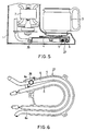
- microcomputer 38 Upon receipt of the detection signal, microcomputer 38 operates to drive brewing case 11. More specifically, a thermistor 39 may be employed as such detecting means, as shown in FIGS. 5 and 6.
- Thermistor 39 is disposed on a portion 6a of heating tube 6 at the reservoir or water inlet side. Thermistor 39 detects the temperature of heating tube 6 to thereby generate a detection signal, which is supplied to microcomputer 38.
- microcomputer 38 When the temperature detected by thermistor 39 reaches a predetermined temperature at which the hot water feed to brewing case 11 is initiated, microcomputer 38 operates so that motor 7 is reverse rotated to drive brewing case 11. Provision of the detecting means such as thermistor 35 is advantageous in that the rotation timing of brewing case 11 may be accurately determined independent of the temperature of water in reservoir 2. Alternatively, motor 7 may be reverse rotated with a predetermined delay period when the temperature detected by thermistor 39 reaches the predetermined temperature. The reason for the disposition of thermistor 39 on portion 6a of heating tube 6 at the reservoir side is that thermistor 39 also serves to detect completion of hot water feed to brewing case 11.
- thermistor 39 when the water in reservoir 2 is all fed and the heating tube 6 is dried up, the temperature of heating tube is rapidly increased. The rapid temperature increase is detected by thermistor 39, thereby accurately determining the completion of hot water feed. Heater 5 may be deenergized upon completion of hot water feed.
- the position of thermistor 39 is not limited to that described above. It may be disposed on a portion 6b of heating tube 6 at the outlet side or on hot water feed arm 26.
- a weight sensor may be provided for measuring the weight of brewing case 11.
- the rotation timing of brewing case 11 may be determined based on changes of weight of brewing case 11 measured by weight sensor.
- a flowmeter may be mounted on hot water feed arm 26 for detecting the flow rate of hot water and the rotation timing of brewing case 11 may be determined based on changes of the detected flow rate.
- a number of small perforations may be formed in the entire peripheral wall of brewing case 11 so as to serve as the filter. Additionally, the coupling structure between inner and outer shafts 10, 12 and mill 9 and brewing case 11 may be changed.
Landscapes
- Engineering & Computer Science (AREA)
- Food Science & Technology (AREA)
- Apparatus For Making Beverages (AREA)
Claims (5)
- Cafetière comprenant un réceptacle (11) pour le breuvage destiné à contenir des grains de café moulus, le réceptacle (11) pour le breuvage comportant un filtre (22) procuré à sa périphérie externe pour la préparation du café, un mécanisme (27) d'alimentation en eau chaude englobant un dispositif de chauffage (5), le mécanisme (27) d'alimentation en eau chaude alimentant en eau chaude le réceptacle (11) pour le breuvage, un moteur électrique (7) procuré pour faire tourner le réceptacle (11) pour le breuvage de telle sorte qu'une force centrifuge s'exerce sur l'eau chaude qui alimente le réceptacle (11) pour le breuvage, faisant ainsi en sorte que l'eau chaude passe à travers les grains de café moulus et ensuite à travers le filtre (22), ainsi qu'un moyen de commande (38) procuré pour commander le mécanisme (27) d'alimentation en eau chaude et le moteur (7), caractérisé en ce que ledit moyen de commande (38) commande le mécanisme (27) d'alimentation en eau chaude et le moteur (7) de telle sorte que le moteur (7) soit entraîné pour faire tourner le réceptacle (11) pour le breuvage après le déclenchement de l'alimentation en eau chaude depuis le mécanisme (27) d'alimentation en eau chaude vers le réceptacle (11) pour le breuvage.
- Cafetière selon la revendication 1, dans laquelle le mécanisme (27) d'alimentation en eau chaude englobe une sortie (26a) pour l'eau chaude disposée au-dessus du réceptacle (11) pour le breuvage de telle sorte que l'eau chaude alimente le réceptacle (11) pour le breuvage par-dessus le réceptacle.
- Cafetière selon la revendication 1, dans laquelle le moyen de commande (38) commande le mécanisme (27) d'alimentation en eau chaude et le moteur (7) de telle sorte que le moteur (7) soit entraîné pour faire tourner le réceptacle (11) pour le breuvage après que l'eau chaude alimentée par le mécanisme (27) d'alimentation en eau chaude ait traversé essentiellement l'ensemble des grains de café moulus dans le réceptacle (11) pour le breuvage.
- Cafetière selon la revendication 1, dans laquelle le moyen de commande (38) commande le mécanisme (27) d'alimentation en eau chaude et le moteur (7) de telle sorte que le moteur (7) soit entraîné pour faire tourner le réceptacle (11) pour le breuvage après qu'une quantité d'eau chaude provenant du mécanisme (27) d'alimentation en eau chaude ait été récoltée dans le réceptacle (11) pour le breuvage.
- Cafetière selon la revendication 1, qui comprend, en outre, un moyen de détection (39) pour détecter le minutage de la rotation du réceptacle (11) pour le breuvage, en générant ainsi un signal de détection et, dans laquelle, en se basant sur le signal de détection, le moyen de commande (38) commande le moteur (7) de façon à faire tourner le réceptacle (11) pour le breuvage.
Applications Claiming Priority (8)
| Application Number | Priority Date | Filing Date | Title |
|---|---|---|---|
| JP63278296A JP2731186B2 (ja) | 1988-11-02 | 1988-11-02 | 飲料抽出器 |
| JP63278295A JPH082335B2 (ja) | 1988-11-02 | 1988-11-02 | コーヒー製造機 |
| JP278295/88 | 1988-11-02 | ||
| JP278296/88 | 1988-11-02 | ||
| JP8169/89 | 1989-01-17 | ||
| JP1008169A JPH02189115A (ja) | 1989-01-17 | 1989-01-17 | コーヒー抽出器 |
| JP35660/89 | 1989-02-15 | ||
| JP1035660A JP2731213B2 (ja) | 1989-02-15 | 1989-02-15 | コーヒー抽出器 |
Publications (2)
| Publication Number | Publication Date |
|---|---|
| EP0367600A1 EP0367600A1 (fr) | 1990-05-09 |
| EP0367600B1 true EP0367600B1 (fr) | 1993-05-12 |
Family
ID=27454890
Family Applications (1)
| Application Number | Title | Priority Date | Filing Date |
|---|---|---|---|
| EP89311341A Expired - Lifetime EP0367600B1 (fr) | 1988-11-02 | 1989-11-02 | Machine à café du type à infusion centrifuge |
Country Status (3)
| Country | Link |
|---|---|
| US (1) | US4962693A (fr) |
| EP (1) | EP0367600B1 (fr) |
| DE (1) | DE68906509T2 (fr) |
Cited By (7)
| Publication number | Priority date | Publication date | Assignee | Title |
|---|---|---|---|---|
| WO2008148834A1 (fr) | 2007-06-05 | 2008-12-11 | Nestec S.A. | Capsule et procédé de préparation d'un liquide alimentaire par centrifugation |
| EP2208449A2 (fr) | 2007-06-05 | 2010-07-21 | Nestec S.A. | Capsule pour la préparation d'une boisson ou d'un aliment liquide et système utilisant la force centrifuge |
| EP2210539A2 (fr) | 2007-06-05 | 2010-07-28 | Nestec S.A. | Appareil et système de préparation d'une boisson utilisant la force centrifuge |
| EP2316309A1 (fr) | 2007-06-05 | 2011-05-04 | Nestec S.A. | Système et procédé de préparation d'un aliment liquide en utilisant la force centrifuge |
| US8475860B2 (en) | 2008-02-29 | 2013-07-02 | Nestec S.A. | Method and system for preparing a liquid extract from a cell using centrifugal forces |
| US8658232B2 (en) | 2009-08-28 | 2014-02-25 | Nestec S.A. | Capsule system for the preparation of beverages by centrifugation |
| RU2700402C2 (ru) * | 2014-11-14 | 2019-09-16 | Конинклейке Филипс Н.В. | Способ и устройство для обработки кофейных зерен |
Families Citing this family (53)
| Publication number | Priority date | Publication date | Assignee | Title |
|---|---|---|---|---|
| US5265517A (en) * | 1991-10-09 | 1993-11-30 | Industria Columbiana De Electronicos Y Electrodomesticos, Incelt S.A. Of Carrera | Method and apparatus for brewing coffee |
| FR2686007B1 (fr) * | 1992-01-10 | 1995-04-14 | Seb Sa | Machine mixte pour la preparation de boissons chaudes telle qu'une cafetiere mixte. |
| US5566605A (en) * | 1993-11-09 | 1996-10-22 | Seb S.A. | Centrifugal type extraction cell having a deformable sealing joint for a hot beverage preparation machine |
| DE4418139C1 (de) | 1994-05-25 | 1995-02-09 | Samaro Eng & Handel | Mahlwerk für Kaffeemühlen |
| US5463932A (en) * | 1995-01-19 | 1995-11-07 | Olson; Allen W. | Coffee maker |
| US5957035A (en) * | 1997-10-10 | 1999-09-28 | Richter; Walter M. | Swirling oscillation coffee maker |
| US5992299A (en) * | 1998-05-21 | 1999-11-30 | Silver Plan Industrial Limited | Coffee makers |
| US6227102B1 (en) * | 1999-04-27 | 2001-05-08 | John C. K. Sham | Automatic coffee maker with grinder |
| US7640843B2 (en) * | 2003-01-24 | 2010-01-05 | Kraft Foods R & D, Inc. | Cartridge and method for the preparation of beverages |
| CN1809303A (zh) | 2003-05-19 | 2006-07-26 | 阿罗玛富丽新有限公司 | 咖啡调制器 |
| US7340991B2 (en) * | 2003-05-19 | 2008-03-11 | Aroma Fresh, Llc | Coffee brewer |
| EP1876934B1 (fr) * | 2005-04-22 | 2011-12-21 | Coffee Innovation Group B.V. | Dispositif destine a preparer le cafe |
| US7581490B2 (en) * | 2005-04-28 | 2009-09-01 | Applica Consumer Products, Inc. | Coffeemaker with water feed velocity decreaser |
| CN101374442B (zh) * | 2005-10-11 | 2011-06-22 | 麦志坚 | 咖啡机 |
| US8431175B2 (en) * | 2007-06-05 | 2013-04-30 | Nestec S.A. | Method for preparing a beverage or food liquid and system using brewing centrifugal force |
| EP2152607B1 (fr) * | 2007-06-05 | 2012-01-11 | Nestec S.A. | Capsule a usage unique pour preparer un liquide alimentaire par centrifugation |
| EP2330953B1 (fr) | 2008-09-02 | 2015-06-03 | Nestec S.A. | Procédé de préparation par centrifugation d'un liquide alimentaire contenu dans une capsule et système conçu pour un tel procédé |
| CA2734935C (fr) * | 2008-09-02 | 2015-02-10 | Nestec S.A. | Dispositif de production controlee de boisson utilisant des forces centrifuges |
| CN102238890B (zh) * | 2008-12-03 | 2014-01-22 | 雀巢产品技术援助有限公司 | 利用离心作用制备饮料的胶囊 |
| RU2527176C2 (ru) | 2008-12-09 | 2014-08-27 | Нестек С.А. | Капсула для приготовления напитка методом центрифугирования и устройство для приготовления напитков |
| WO2010066736A1 (fr) | 2008-12-09 | 2010-06-17 | Nestec S.A. | Système de préparation d'aliment liquide pour préparer un aliment liquide par centrifugation |
| US20100212509A1 (en) * | 2009-02-20 | 2010-08-26 | Pao-Wu Tien | Safety and guide type brewing kettle |
| EP2308776B1 (fr) * | 2009-08-19 | 2013-05-29 | Nestec S.A. | Système à capsule comprenant une capsule et un dispositif d'injection d'eau |
| JP5722895B2 (ja) | 2009-08-28 | 2015-05-27 | ネステク ソシエテ アノニム | 遠心法による飲料調製用カプセルシステム |
| JP2011161223A (ja) * | 2010-01-15 | 2011-08-25 | Suntory Holdings Ltd | コーヒー抽出装置 |
| US9066623B2 (en) * | 2010-11-15 | 2015-06-30 | Conair Corporation | Brewed beverage appliance and method |
| US8573115B2 (en) * | 2010-11-15 | 2013-11-05 | Conair Corporation | Brewed beverage appliance and method |
| NZ613677A (en) * | 2011-01-17 | 2014-12-24 | Suntory Beverage & Food Ltd | Beverage extraction apparatus |
| USD677510S1 (en) | 2011-06-16 | 2013-03-12 | Calphalon Corporation | Coffee maker |
| CA2842145C (fr) * | 2011-08-09 | 2019-06-11 | Nestec S.A. | Machine de brassage centrifuge ayant un ensemble de collecte d'ecoulement |
| CN103284606B (zh) * | 2012-02-27 | 2016-04-20 | 美的集团股份有限公司 | 一种磨豆式咖啡机 |
| WO2014102048A1 (fr) * | 2012-12-06 | 2014-07-03 | Nestec S.A. | Dispositif de préparation d'une boisson par centrifugation |
| CN103040361B (zh) * | 2013-01-08 | 2015-08-26 | 周林斌 | 一种磨豆咖啡机器 |
| CN203138096U (zh) * | 2013-01-08 | 2013-08-21 | 周林斌 | 咖啡壶过滤装置 |
| DE102013210107A1 (de) * | 2013-05-29 | 2014-12-04 | BSH Bosch und Siemens Hausgeräte GmbH | Kaffeevollautomat mit einer Zentrifugierkammer |
| JP6214411B2 (ja) * | 2014-01-31 | 2017-10-18 | シャープ株式会社 | 飲料製造装置 |
| JP6289130B2 (ja) * | 2014-01-31 | 2018-03-07 | シャープ株式会社 | 飲料製造装置 |
| US9307860B2 (en) | 2014-02-14 | 2016-04-12 | Remington Designs, Llc | Processor control of solute extraction system |
| CN104840103A (zh) * | 2015-04-28 | 2015-08-19 | 周林斌 | 一种磨豆咖啡壶的流水装置 |
| CN105266657B (zh) * | 2015-11-09 | 2017-12-22 | 广东新宝电器股份有限公司 | 咖啡机及过滤引流筒 |
| US10542839B2 (en) | 2015-12-30 | 2020-01-28 | Conair Corporation | Coffee making appliance |
| US10004354B2 (en) * | 2015-12-30 | 2018-06-26 | Conair Corporation | Coffee making appliance for brewing coffee |
| KR101716316B1 (ko) | 2016-05-25 | 2017-03-14 | 주식회사 태성트레이딩 | 원심력을 이용한 커피액 추출장치 |
| CN107811511B (zh) * | 2016-09-14 | 2019-11-08 | 广东美的生活电器制造有限公司 | 咖啡机 |
| CN107811514B (zh) * | 2016-09-14 | 2019-11-08 | 广东美的生活电器制造有限公司 | 咖啡机 |
| CN107811513B (zh) * | 2016-09-14 | 2019-09-20 | 广东美的生活电器制造有限公司 | 咖啡机以及咖啡制备方法 |
| JP6647393B2 (ja) * | 2016-09-14 | 2020-02-14 | 広東美的生活電器制造有限公司Guangdong Midea Consumer Electrics Manufacturing Co., Ltd. | コーヒーメーカーおよびコーヒー製造方法 |
| US10806293B2 (en) | 2016-09-29 | 2020-10-20 | Guangdong Midea Consumer Electrics Manufacturing Co., Ltd. | Coffee machine screen and coffee machine |
| CN107874621B (zh) * | 2016-09-29 | 2019-12-06 | 广东美的生活电器制造有限公司 | 咖啡机滤网和咖啡机 |
| USD833792S1 (en) | 2017-02-14 | 2018-11-20 | Hamilton Beach Brands, Inc. | Coffeemaker |
| CA3077519A1 (fr) * | 2017-08-31 | 2019-03-07 | Innovative Brewing, Llc | Systemes et procedes d'infusion de cafe boisson |
| DE102021104742B3 (de) * | 2021-02-26 | 2022-09-01 | Ivan Mallinowski | Verfahren und Vorrichtung zum Herstellen einer Suspension |
| WO2024068861A1 (fr) * | 2022-09-30 | 2024-04-04 | Ivan Mallinowski | Procédé et dispositif de production de suspension |
Family Cites Families (9)
| Publication number | Priority date | Publication date | Assignee | Title |
|---|---|---|---|---|
| US1789334A (en) * | 1929-05-21 | 1931-01-20 | Leonard H Englund | Method and apparatus for making infusions |
| US2149270A (en) * | 1933-02-16 | 1939-03-07 | Burgess Louis | Coffee maker |
| GB887212A (en) * | 1957-06-15 | 1962-01-17 | Philips Nv | Improvements in centrifuges for producing coffee filtrate |
| DE2151920A1 (de) * | 1971-04-03 | 1973-04-26 | Guenther Hultsch | Kaffeemaschine mit mahlvorrichtung |
| FR2132310B1 (fr) * | 1971-04-03 | 1975-06-20 | Hultsch Guenther | |
| US4196658A (en) * | 1977-11-30 | 1980-04-08 | Tokyo Shibaura Denki Kabushiki Kaisha | Coffee-pot and coffee-mill combination |
| AT391257B (de) * | 1981-09-22 | 1990-09-10 | Bosch Siemens Hausgeraete | Elektrische kaffeemaschine mit einem zentrifugalfilter |
| DE3137651A1 (de) * | 1981-09-22 | 1983-04-14 | Bosch-Siemens Hausgeräte GmbH, 7000 Stuttgart | Auslauf fuer einen getraenkebereiter |
| EP0280794A1 (fr) * | 1987-03-03 | 1988-09-07 | Animo B.V. | Procédé et dispositif pour préparer des boissons chaudes |
-
1989
- 1989-11-01 US US07/429,980 patent/US4962693A/en not_active Expired - Fee Related
- 1989-11-02 DE DE89311341T patent/DE68906509T2/de not_active Expired - Fee Related
- 1989-11-02 EP EP89311341A patent/EP0367600B1/fr not_active Expired - Lifetime
Cited By (13)
| Publication number | Priority date | Publication date | Assignee | Title |
|---|---|---|---|---|
| CN101687592B (zh) * | 2007-06-05 | 2011-07-20 | 雀巢产品技术援助有限公司 | 用于通过离心法来制备液态食品的胶囊和方法 |
| EP2208449A2 (fr) | 2007-06-05 | 2010-07-21 | Nestec S.A. | Capsule pour la préparation d'une boisson ou d'un aliment liquide et système utilisant la force centrifuge |
| EP2210538A2 (fr) | 2007-06-05 | 2010-07-28 | Nestec S.A. | Capsule de préparation d'une boisson ou d'un aliment liquide et système utilisant la force centrifuge |
| EP2210539A2 (fr) | 2007-06-05 | 2010-07-28 | Nestec S.A. | Appareil et système de préparation d'une boisson utilisant la force centrifuge |
| EP2316309A1 (fr) | 2007-06-05 | 2011-05-04 | Nestec S.A. | Système et procédé de préparation d'un aliment liquide en utilisant la force centrifuge |
| EP2316310A1 (fr) | 2007-06-05 | 2011-05-04 | Nestec S.A. | Système et procédé de préparation d'un aliment liquide à partir d'un material contenu dans un réceptacle par centrifugation |
| WO2008148834A1 (fr) | 2007-06-05 | 2008-12-11 | Nestec S.A. | Capsule et procédé de préparation d'un liquide alimentaire par centrifugation |
| US8986764B2 (en) | 2007-06-05 | 2015-03-24 | Nestec S.A. | Capsule and method for preparing a food liquid by centrifugation |
| US9271598B2 (en) | 2007-06-05 | 2016-03-01 | Nestec S.A. | Method for preparing a food liquid contained in a capsule by centrifugation and device adapted for such method |
| US9277837B2 (en) | 2007-06-05 | 2016-03-08 | Nestec S.A. | Method for preparing a beverage or liquid food and system using brewing centrifugal force |
| US8475860B2 (en) | 2008-02-29 | 2013-07-02 | Nestec S.A. | Method and system for preparing a liquid extract from a cell using centrifugal forces |
| US8658232B2 (en) | 2009-08-28 | 2014-02-25 | Nestec S.A. | Capsule system for the preparation of beverages by centrifugation |
| RU2700402C2 (ru) * | 2014-11-14 | 2019-09-16 | Конинклейке Филипс Н.В. | Способ и устройство для обработки кофейных зерен |
Also Published As
| Publication number | Publication date |
|---|---|
| DE68906509T2 (de) | 1993-09-30 |
| DE68906509D1 (de) | 1993-06-17 |
| EP0367600A1 (fr) | 1990-05-09 |
| US4962693A (en) | 1990-10-16 |
Similar Documents
| Publication | Publication Date | Title |
|---|---|---|
| EP0367600B1 (fr) | Machine à café du type à infusion centrifuge | |
| JP3245237B2 (ja) | コーヒーを淹れる方法および装置 | |
| US4838152A (en) | Auto-off coffee brewing system | |
| US5463932A (en) | Coffee maker | |
| EP0248490B1 (fr) | Appareil ménager électrique et automatique pour la production de fromage et de ses sous-produits | |
| US4888467A (en) | Machine for making coffee and other hot beverages | |
| US4545296A (en) | Centrifugal apparatus for making coffee | |
| US5992299A (en) | Coffee makers | |
| US11684199B2 (en) | Apparatus for beverage brewing | |
| JP2731213B2 (ja) | コーヒー抽出器 | |
| JPH08107826A (ja) | コーヒー沸かし器 | |
| KR920004262B1 (ko) | 커피 추출기 | |
| JPH0710679Y2 (ja) | コーヒー製造機 | |
| JP3052222B2 (ja) | コーヒー沸かし器 | |
| JPH082335B2 (ja) | コーヒー製造機 | |
| JPH0710676Y2 (ja) | コーヒー抽出器 | |
| JP2970378B2 (ja) | コーヒー製造器 | |
| JP3684299B2 (ja) | コーヒーメーカ | |
| JPH0632035Y2 (ja) | 飲料製造機 | |
| JPS631839Y2 (fr) | ||
| JPH0710677Y2 (ja) | コーヒー抽出器 | |
| JPS631833Y2 (fr) | ||
| JP2000051102A (ja) | コーヒーメーカ | |
| JPS631834Y2 (fr) | ||
| JPS631836Y2 (fr) |
Legal Events
| Date | Code | Title | Description |
|---|---|---|---|
| PUAI | Public reference made under article 153(3) epc to a published international application that has entered the european phase |
Free format text: ORIGINAL CODE: 0009012 |
|
| 17P | Request for examination filed |
Effective date: 19891116 |
|
| AK | Designated contracting states |
Kind code of ref document: A1 Designated state(s): DE FR GB IT NL |
|
| 17Q | First examination report despatched |
Effective date: 19911007 |
|
| GRAA | (expected) grant |
Free format text: ORIGINAL CODE: 0009210 |
|
| AK | Designated contracting states |
Kind code of ref document: B1 Designated state(s): DE FR GB IT NL |
|
| ITF | It: translation for a ep patent filed |
Owner name: BUGNION S.P.A. |
|
| REF | Corresponds to: |
Ref document number: 68906509 Country of ref document: DE Date of ref document: 19930617 |
|
| ET | Fr: translation filed | ||
| REG | Reference to a national code |
Ref country code: GB Ref legal event code: 746 Effective date: 19980917 |
|
| PGFP | Annual fee paid to national office [announced via postgrant information from national office to epo] |
Ref country code: GB Payment date: 19981106 Year of fee payment: 10 Ref country code: DE Payment date: 19981106 Year of fee payment: 10 |
|
| PGFP | Annual fee paid to national office [announced via postgrant information from national office to epo] |
Ref country code: FR Payment date: 19981110 Year of fee payment: 10 |
|
| PGFP | Annual fee paid to national office [announced via postgrant information from national office to epo] |
Ref country code: NL Payment date: 19981126 Year of fee payment: 10 |
|
| REG | Reference to a national code |
Ref country code: FR Ref legal event code: D6 |
|
| PG25 | Lapsed in a contracting state [announced via postgrant information from national office to epo] |
Ref country code: GB Free format text: LAPSE BECAUSE OF NON-PAYMENT OF DUE FEES Effective date: 19991102 |
|
| PG25 | Lapsed in a contracting state [announced via postgrant information from national office to epo] |
Ref country code: NL Free format text: LAPSE BECAUSE OF NON-PAYMENT OF DUE FEES Effective date: 20000601 |
|
| GBPC | Gb: european patent ceased through non-payment of renewal fee |
Effective date: 19991102 |
|
| PG25 | Lapsed in a contracting state [announced via postgrant information from national office to epo] |
Ref country code: FR Free format text: LAPSE BECAUSE OF NON-PAYMENT OF DUE FEES Effective date: 20000731 |
|
| NLV4 | Nl: lapsed or anulled due to non-payment of the annual fee |
Effective date: 20000601 |
|
| PG25 | Lapsed in a contracting state [announced via postgrant information from national office to epo] |
Ref country code: DE Free format text: LAPSE BECAUSE OF NON-PAYMENT OF DUE FEES Effective date: 20000901 |
|
| REG | Reference to a national code |
Ref country code: FR Ref legal event code: ST |
|
| PG25 | Lapsed in a contracting state [announced via postgrant information from national office to epo] |
Ref country code: IT Free format text: LAPSE BECAUSE OF NON-PAYMENT OF DUE FEES;WARNING: LAPSES OF ITALIAN PATENTS WITH EFFECTIVE DATE BEFORE 2007 MAY HAVE OCCURRED AT ANY TIME BEFORE 2007. THE CORRECT EFFECTIVE DATE MAY BE DIFFERENT FROM THE ONE RECORDED. Effective date: 20051102 |
|
| PLBE | No opposition filed within time limit |
Free format text: ORIGINAL CODE: 0009261 |
|
| STAA | Information on the status of an ep patent application or granted ep patent |
Free format text: STATUS: NO OPPOSITION FILED WITHIN TIME LIMIT |