EP0367600A1 - Centrifugal brewing type coffee maker - Google Patents
Centrifugal brewing type coffee maker Download PDFInfo
- Publication number
- EP0367600A1 EP0367600A1 EP89311341A EP89311341A EP0367600A1 EP 0367600 A1 EP0367600 A1 EP 0367600A1 EP 89311341 A EP89311341 A EP 89311341A EP 89311341 A EP89311341 A EP 89311341A EP 0367600 A1 EP0367600 A1 EP 0367600A1
- Authority
- EP
- European Patent Office
- Prior art keywords
- hot water
- brewing
- case
- motor
- brewing case
- Prior art date
- Legal status (The legal status is an assumption and is not a legal conclusion. Google has not performed a legal analysis and makes no representation as to the accuracy of the status listed.)
- Granted
Links
Images


Classifications
-
- A—HUMAN NECESSITIES
- A47—FURNITURE; DOMESTIC ARTICLES OR APPLIANCES; COFFEE MILLS; SPICE MILLS; SUCTION CLEANERS IN GENERAL
- A47J—KITCHEN EQUIPMENT; COFFEE MILLS; SPICE MILLS; APPARATUS FOR MAKING BEVERAGES
- A47J31/00—Apparatus for making beverages
- A47J31/22—Centrifuges for producing filtered coffee
-
- A—HUMAN NECESSITIES
- A47—FURNITURE; DOMESTIC ARTICLES OR APPLIANCES; COFFEE MILLS; SPICE MILLS; SUCTION CLEANERS IN GENERAL
- A47J—KITCHEN EQUIPMENT; COFFEE MILLS; SPICE MILLS; APPARATUS FOR MAKING BEVERAGES
- A47J31/00—Apparatus for making beverages
- A47J31/42—Beverage-making apparatus with incorporated grinding or roasting means for coffee
Definitions
- This invention relates to coffee makers for centrifugally brewing coffee by rotating a brewing case containing milled coffee beans at high speed by a motor with hot water simultaneously fed to the brewing case from a hot water feed mechanism.
- Coffee makers of the type described above are suitable for preparing "espresso"-like coffee and disclosed in Japanese Laid-open Utility Model Application No. 63-37142 and German Patent No. DE 3137651 A1.
- a brewing case for containing milled coffee beans is provided above an electric motor and a small space is defined between the upper peripheral edge of the brewing case and a lid closing the upper open end of the brewing case.
- the brewing case is rotated at high speed by the motor so that a centrifugal force due to rotation causes hot water to quickly pass through the milled coffee beans and then through the small space between the case and the lid, thereby making coffee.
- This coffee brewing manner is advantageous in that coffee is quickly made. Further, since a period during which the hot water is in contact with the milled coffee beans is relatively short, ingredients degrading flavor of coffee such as the ingredient of bitterness are not extracted from the milled coffee beans, thereby improving the flavor of coffee.
- a heating case is provided below the brewing case for heating the water therein.
- a hot water feed tube is extended downwardly from the central bottom of the brewing case to the interior of the heating case. After the hot water is made in the heating case, the brewing case and the hot water feed tube are together rotated at high speed, whereby the hot water in the heating case is sucked to the brewing case through the hot water feed tube. Consequently, the hot water supply to the brewing case necessarily starts after the start of rotation of the brewing case.
- the coffee maker disclosed in the above-mentioned German Patent is not provided with a hot water feed mechanism and accordingly, a user needs to supply hot water with a kettle or the like. Therefore, a lot of time is needed for the making of coffee and the usability is reduced.
- an object of the present invention is to provide a centrifugal brewing type coffee maker wherein the oscillation of the brewing case with high speed rotation thereof at a brewing step can be reduced and the noise reduction can be enhanced.
- the present invention provides a coffee maker comprising a brewing case for containing milled coffee beans, the brewing case having a filter provided at the outer periphery thereof for coffee brewing, a hot water feed mechanism including a heater, the hot water feed mechanism feeding hot water to the brewing case, an electric motor provided for rotating the brewing case so that a centrifugal force is applied to the hot water fed into the brewing case, thereby causing the hot water to pass through the milled coffee beans and then, through the filter, and control means for controlling the hot water feed mechanism and the motor so that the motor is driven to rotate the brewing case after the hot water feed is initiated from the hot water feed mechanism to the brewing case.
- the hot water is uniformly permeated into the milled coffee beans in the brewing case before the brewing case is rotated, thereby balancing the brewing case. Consequently, oscillation of the brewing case during rotation may be effectively reduced. Additionally, since the hot water is automatically fed to the brewing case by the hot water feed mechanism, a user is not troubled for the hot water feed.
- the hot water feed mechanism include a hot water outlet disposed above the brewing case so that the hot water is fed to the brewing case from above the same.
- This arrangement of the outlet of the hot water feed mechanism is advantageous in that the hot water feed may be facilitated.
- control means control the hot water feed mechanism and the motor so that the motor is driven to rotate the brewing case after substantially the entire milled coffee beans in the brewing case is wetted with the hot water fed by the hot water feed mechanism.
- the reason for this is that should the milled coffee beans include wet and unwet parts, the unwet milled coffee beans adheres to the wet milled coffee beans into lumps of milled coffee beans, which unbalances the brewing case.
- the motor may be driven to rotate the brewing case after the hot water is fed to the brewing case and reserved therein. When the hot water is reserved in the brewing case, the entire milled coffee beans is necessarily immersed in the hot water such that the brewing case keeps its balance or balanced.
- the coffee maker may include detecting means for detecting a timing of rotating the brewing case, thereby generating a detection signal. Based on the detection signal, the control means may control the motor so that the brewing case is rotated. Provision of the detecting means is advantageous in that the timing of starting the rotation of the brewing case may be accurately determined.
- the invention may also be practiced by a coffee maker comprising a brewing case for containing milled coffee beans, the brewing case having a filter provided at the outer periphery thereof for coffee brewing, a coffee mill rotatably mounted in the brewing case for milling coffee beans, a hot water feed mechanism including a heater, the hot water feed mechanism feeding hot water to the brewing case, an electric motor provided for driving the mill in a milling step and the brewing case in a brewing step, and a clutch mechanism for selectively transmitting rotation of the motor either to the brewing case or the mill, the clutch mechanism transmitting rotation of the motor to the mill in the milling step, the clutch mechanism transmitting rotation of the motor to the brewing case in a brewing step so that the brewing case is rotated such that a centrifugal force is applied to the hot water fed into the brewing case, thereby causing the hot water to pass through the milled coffee beans and then, through the filter.
- a coffee maker comprising a brewing case for containing mill
- the motor When coffee beans are contained in the brewing case, the motor is driven. Rotation of the motor is transmitted through the clutch mechanism to the coffee mill, which is driven to mill the coffee beans.
- the brewing step is initiated by feeding hot water from the hot water feed mechanism into the brewing case containing milled coffee beans. Rotation of the motor is then transmitted through the clutch mechanism to the brewing case, thereby rotating the brewing case. A centrifugal force due to rotation is applied to the hot water fed into the brewing case so that the hot water passes through the milled coffee beans and then, the filter provided on the outer periphery of the brewing case.
- a single brewing case may be utilized for both of the milling and brewing operations and a single motor is utilized for selectively rotating the mill and brewing case, thereby facilitating simplified construction of the coffee maker and compactness of its size. Consequently, the coffee maker of the invention is advantageous when applied to household coffee makers.
- the motor may be driven to rotate the brewing case after the hot water feed is initiated from the hot water feed mechanism to the brewing case.
- the hot water is uniformly permeated into the milled coffee beans in the brewing case before the brewing case is rotated, thereby balancing the brewing case. Consequently, oscillation of the brewing case during rotation may be effectively reduced. Additionally, since the hot water is automatically fed to the brewing case by the hot water feed mechanism, a user is not troubled for the hot water feed.
- the clutch mechanism have the construction of a one-way clutch and that the motor be rotated in the milling step in the direction opposite to that in the brewing step.
- the construction of the clutch mechanism may be simplified, which contributes reduction of the production cost of the coffee maker.
- the motor be rotated in the brewing step at the speed lower than that in the milling step. The reason for this is that since the external diameter is larger than that of the coffee mill, necessary peripheral speed may be ensured even when the motor speed is reduced, thereby causing a centrifugal force necessary for the coffee brewing. In this respect, the noise due to oscillation of the brewing case may be reduced during the brewing step when the motor speed is reduced.
- the invention may be further practiced by a coffee maker comprising a base, a brewing case provided at the upper portion of the base for containing milled coffee beans, the brewing case having a filter provided at the outer periphery thereof for coffee brewing, a coffee mill rotatively mounted in the brewing case for milling coffee beans, an electric motor provided at the lower side of the base for driving the mill in a milling step and the brewing case in a brewing step, a water reservoir provided at one side of the base for reserving water, a hot water feed mechanism including an electric heater and a heating pipe provided at the lower side of the base, the hot water feed mechanism making hot water from the water supplied from the water reservoir, the hot water feed mechanism feeding the hot water to the brewing case, a clutch mechanism provided between the brewing case and mill and the motor for transmitting rotation of the motor to the mill in the milling step, the clutch mechanism transmitting rotation of the motor to the brewing case in the brewing step so that the brewing case is rotated such that a centri
- the above-described construction may provide reasonable arrangements of the brewing case, motor, reservoir, and receiver, thereby facilitating compactness of the household coffee maker.
- a coffee maker embodying the invention comprises a base 1.
- a cartridge type water reservoir 2 is disposed on the left side of the base 1 and a hot plate 4 is provided on the lower right-hand side of the base 1, on which plate a receiver 3 for reserving coffee fluid is placed.
- An electric heater 5 and a heating tube 6 are provided on the underside of hot plate 4. Water in reservoir 2 is supplied to the heating tube 6.
- An electric motor 7 of a vertical shaft type is provided between reservoir 2 and receiver 3. Motor 7 is specifically a commutator motor forward and reverse rotated.
- An inner shaft 10 for driving a coffee mill 9 described later is vertically secured to an upper end of an upwardly extended rotational shaft 8 of motor 7.
- a hollow outer shaft 12 for rotating a brewing case 11 described later is fitted with inner shaft 10 for relative rotation.
- Outer shaft 12 is rotatably mounted on a bearing 13 provided with sealing function.
- a clutch mechanism 14 is provided for selectively transmitting the rotation of motor 7 to outer shaft 12.
- Clutch mechanism 14 comprises a coil spring wound around a lower end large diameter portion 10a of inner shaft 10 and the lower portion of outer shaft 12 and the lower end of coil spring 15 is secured to lower end large diameter portion 10a of inner shaft 10 by a lock pin 16.
- Clutch mechanism 14 is constructed as a frictional one-way clutch. Therefore, coil spring 15 is wound off against outer shaft 12 during the forward rotation of motor 7 with the result that rotation of motor 7 is not transmitted to outer shaft 12, with only inner shaft 10 rotated. When motor 7 is reverse rotated, a frictional force causes coil spring 15 to wind up against outer shaft 12, thereby rotating both shafts 10 and 12 together.
- a collector case 17 is detachably provided above clutch mechanism 14.
- Collector case 17 has an outlet 18 formed through the right-hand end of a bottom wall thereof, as viewed in FIGS. 1 and 2.
- Outlet 18 of collector case 17 faces an upper opening of receiver 3.
- a brewing case 11 utilized for both of milling and brewing operations is enclosed in collector case 17.
- brewing case 11 has an annular joint 19 formed on the bottom thereof and downwardly extended.
- An upper end coupling portion 12a of outer shaft 12 is fitted in with joint 19, thereby holding brewing case 11 in position.
- the inner peripheral surface of joint 19 and the outer peripheral surface of coupling portion 12a of outer shaft 12 are formed so as to have a concave and convex relationship to each other, thereby preventing simultaneous rotation of them.
- a mill 9 is rotatably mounted in brewing case 11.
- Mill 9 has a coupling opening 20a formed under a shaft 20 thereof, to which opening the upper end of inner shaft 10 is coupled.
- Brewing case 11 has an upper opening covered by a lid 21 having a central opening 21a through which hot water falls down into brewing case 11.
- a space having the width of, for example, approximately 0.2 mm is defined between brewing case 11 and lid 21 uniformly along the entire peripheries of them. The space serves as a filter 22.
- Case 11 has a downwardly tapered inner surface so that the centrifugal force due to rotation causes the coffee fluid or hot water to rise toward filter 22.
- Lid 21 has an engagement claw 23 which is engaged with a bayonet engagement groove 24 formed in the upper edge portion of brewing case 11, thereby fixing lid 21 to brewing case 11.
- Collector case 17 also has an upper open end covered by another lid 25 having a central opening 25a through which hot water falls down onto lid 22.
- Hot water feed arm 26 is provided above lid 25 so as to be horizontally pivoted. Hot water feed arm 26 is communicated to heating pipe 6 and has an outlet 26a positioned right above opening 25a. Hot water feed arm 26, heating pipe 6 and heater 5 constitute a hot water feed mechanism 27. A cover 28 covers the upper side of base 1 of the coffee maker.
- Two switches 31 and 32 are provided for reversing the flow of an electrical current to field coils 7a and 7b and an armature coil 7c of motor 7. Further, a switch 33 for forward rotation is connected between field coil 7b and a power line 34 and a series circuit of a resistance 35 and a switch 36 for reverse rotation is connected in parallel with forward rotation switch 33.
- a movable contact 31a of switch 31 is engaged with a fixed contact 31b thereof and a movable contact 32a of switch 32 is engaged with a fixed contact 32b thereof. Further, forward rotation switch 33 is turned on for execution of the milling step.
- motor 7 is forward rotated at 10,000 rpm, for example.
- movable contact 31a of switch 31 is switched to a fixed contact 31c thereof and movable contact 32a of switch 32 is switched to a fixed contact 32c.
- reverse rotation switch 36 is turned on, with the result that motor 7 is reverse rotated at 5,000 rpm, for example.
- the motor revolution in the reverse rotation is decreased to a half of that in the forward rotation because resistance 35 reduces the voltage applied to motor 7.
- a heater switch 37 is provided in a power line thereto. Switching operations of switches 31, 32, 33, 36 and 37 are controlled by a microcomputer 38 serving as control means.
- microcomputer 38 After completion of the milling step, microcomputer 38 operates to energize heater 5 (or to turn on heater switch 37) for making of hot water.
- the timing for reversing the motor rotation is set in microcomputer 38 so that motor 7 is reverse rotated (or switch 36 is turned on) when substantially the entire milled coffee beans is permeated with the hot water fed into brewing case 11.
- the timing for reversing the motor rotation is determined by a timer which starts the time-counting operation simultaneously with the start of energization of heater 5.
- Motor 7 is reverse rotated at the time when the timer accumulated period reaches a predetermined period previously obtained by an experiment.
- FIG. 4 illustrates the relationship between the directions of motor rotation and an energization period of heater 5.
- microcomputer 38 operates so that movable contact 31a of switch 31 is engaged with fixed contact 31b and so that movable contact 32a of switch 32 is engaged with fixed contact 32b.
- microcomputer 38 further operates to turn on forward rotation switch 33 so that motor 7 forward rotates at 10,000 rpm, for example. Consequently, mill 9 is driven to mill the coffee beans in brewing case 11.
- motor 7 rotates in the same direction that coil spring 15 of clutch mechanism 14 is wound off against outer shaft 12. Accordingly, rotation of motor 7 is not transmitted to outer shaft 12, with the result that brewing case 11 is stationary in the milling step.
- microcomputer 38 operates to turn off forward rotation switch 33 to temporally deenergize motor 7.
- heater switch 37 is turned on so that heater 5 is energized, whereby the water fed to heating pipe 6 from reservoir 2 is sequentially heated, thereby obtaining hot water.
- the boiling pressure raises the hot water to hot water feed arm 26 sequentially.
- the hot water fed to feed arm 26 is then fed into brewing case 11 through outlets 25a and 21a of respective lids 25 and 21.
- microcomputer 38 operates to engage movable contact 31a of switch 31 with fixed contact 31c and to engage movable contact 32a of switch 32 with fixed contact 32c.
- Microcomputer 38 further operates to turn on reverse rotation switch 36. Consequently, motor 7 reverse rotates at 5,000 rpm, for example. Since motor 7 rotates in the direction that coil spring 15 of clutch mechanism 14 is wound up, coil spring 15 is wound up against the outer periphery of outer shaft 12, whereby rotation of motor 7 is transmitted to outer shaft 12 as well as inner shaft 10. Inner and outer shafts 10 and 12 are thus rotated together such that brewing case 11 is rotated at high speed with mill 9.
- the hot water is discharged from feed arm 26 toward the inner central portion of brewing case 11 to be thereby received by mill 9 and inner bottom of brewing case 11.
- Rotation of mill 9 shakes off the hot water received by the mill in the direction that the centrifugal force acts and consequently, the hot water is dispersed around to thereby permeate coffee ground A from the inner peripheral side.
- the centrifugal force due to rotation of brewing case 11 causes the hot water received by the inner bottom thereof to permeate milled coffee beans A through the brewing case inner bottom surface.
- the hot water having thus permeated milled coffee beans A passes therethrough relatively promptly owing to the centrifugal force with coffee ingredients extracted and reaches the inner surface of the brewing case peripheral wall.
- the hot water containing coffee ingredients is further caused to rise along the tapered inner peripheral wall surface and disperse around from filter 22 to be thereby received by the inner peripheral wall of collector case 17.
- the coffee fluid thus received by the inner peripheral wall of collector case 17 flows downward along the wall, falling downward from outlet 18 into receiver 3. Since the centrifugal force due to rotation of brewing case 11 causes the hot water to pass through milled coffee beans A relatively promptly, only essential fragrant ingredients are extracted and those degrading the flavor of coffee are not extracted, thereby improving the coffee flavor.
- brewing case 11 is rotated after the hot water feed to the brewing case is initiated. Accordingly, brewing case 11 is stationary at an initial stage of the hot water feed and the hot water uniformly permeates the entire milled coffee beans in brewing case 11, with the result that brewing case 11 is balanced. Consequently, rotation of brewing case 7 may be stabilized from the first, thereby reducing oscillation due to the unbalanced state of brewing case 11 and reducing the noise. Additionally, since the hot water feed to brewing case 11 is automatically performed, coffee may be easily made without trouble of a user.
- motor 7 is preferably started to drive brewing case 11 after the hot water feed by hot water feed mechanism 27 is initiated such that the entire milled coffee beans in brewing case 11 is wetted with the hot water.
- the reason for this is that should the milled coffee beans include wet and unwet parts, the unwet milled coffee beans adheres to the wet milled coffee beans into lumps of milled coffee beans, which unbalances the brewing case.
- motor 7 may be driven to rotate brewing case 11 after the hot water is fed to brewing case 11 to be reserved therein. When the hot water is reserved in the brewing case, the entire milled coffee beans is necessarily permeated with the hot water such that the brewing case keeps its balance or balanced.
- Mill 9 is rotatably mounted in brewing case 11 and clutch mechanism 14 is provided for selectively transmitting rotation of motor 7 to brewing case 11 and mill 9. Consequently, a single brewing case may be utilized for both of the milling and brewing operations and a single motor as a drive source may be employed for driving mill 9 and brewing case 11. Consequently, the invention provides a coffee maker simple in construction and compact in size and the coffee maker of the invention is advantageous when applied to a house hold coffee maker.
- Clutch mechanism 14 has the construction of a one-way clutch and motor 7 may be forward and reverse rotated. Consequently, mill 9 and brewing case 11 may be selectively rotated. Further, since the construction of clutch mechanism 14 is simplified, the production cost of the coffee maker may be reduced. Additionally, although the one-way clutch comprises coil spring 15 in the foregoing embodiment, a sprag clutch or other type one-way clutches may be employed. Moreover, the clutch mechanism is not limited to the one-way clutches. For example, an electromagnetic clutch, a conical friction clutch, a disc clutch or the like may be employed. In each of these clutches, the clutch is operated before the start of the brewing step so that brewing case is driven. The motor is not needed to change its direction of rotation.
- the motor Since the motor is driven in the brewing step at the speed lower than that in the milling step, the noise due to oscillation may be reduced in the brewing step.
- the motor speed is decreased in the brewing step, a sufficient peripheral speed of brewing case 11 may be ensured since the outer diameter of the brewing case is larger than that of mill 9, thereby ensuring a sufficient centrifugal force for the coffee brewing.
- detecting means may be provided for detecting the rotation timing of brewing case 11, instead.
- the detecting means When detecting the rotation timing of brewing case 11, the detecting means generates a detection signal, which is supplied to microcomputer 38.
- microcomputer 38 Upon receipt of the detection signal, microcomputer 38 operates to drive brewing case 11. More specifically, a thermistor 39 may be employed as such detecting means, as shown in FIGS. 5 and 6.
- Thermistor 39 is disposed on a portion 6a of heating tube 6 at the reservoir or water inlet side. Thermistor 39 detects the temperature of heating tube 6 to thereby generate a detection signal, which is supplied to microcomputer 38.
- microcomputer 38 When the temperature detected by thermistor 39 reaches a predetermined temperature at which the hot water feed to brewing case 11 is initiated, microcomputer 38 operates so that motor 7 is reverse rotated to drive brewing case 11. Provision of the detecting means such as thermistor 35 is advantageous in that the rotation timing of brewing case 11 may be accurately determined independent of the temperature of water in reservoir 2. Alternatively, motor 7 may be reverse rotated with a predetermined delay period when the temperature detected by thermistor 39 reaches the predetermined temperature. The reason for the disposition of thermistor 39 on portion 6a of heating tube 6 at the reservoir side is that thermistor 39 also serves to detect completion of hot water feed to brewing case 11.
- thermistor 39 when the water in reservoir 2 is all fed and the heating tube 6 is dried up, the temperature of heating tube is rapidly increased. The rapid temperature increase is detected by thermistor 39, thereby accurately determining the completion of hot water feed. Heater 5 may be deenergized upon completion of hot water feed.
- the position of thermistor 39 is not limited to that described above. It may be disposed on a portion 6b of heating tube 6 at the outlet side or on hot water feed arm 26.
- a weight sensor may be provided for measuring the weight of brewing case 11.
- the rotation timing of brewing case 11 may be determined based on changes of weight of brewing case 11 measured by weight sensor.
- a flowmeter may be mounted on hot water feed arm 26 for detecting the flow rate of hot water and the rotation timing of brewing case 11 may be determined based on changes of the detected flow rate.
- a number of small perforations may be formed in the entire peripheral wall of brewing case 11 so as to serve as the filter. Additionally, the coupling structure between inner and outer shafts 10, 12 and mill 9 and brewing case 11 may be changed.
Landscapes
- Engineering & Computer Science (AREA)
- Food Science & Technology (AREA)
- Apparatus For Making Beverages (AREA)
Abstract

Description
- This invention relates to coffee makers for centrifugally brewing coffee by rotating a brewing case containing milled coffee beans at high speed by a motor with hot water simultaneously fed to the brewing case from a hot water feed mechanism.
- Coffee makers of the type described above are suitable for preparing "espresso"-like coffee and disclosed in Japanese Laid-open Utility Model Application No. 63-37142 and German Patent No. DE 3137651 A1. A brewing case for containing milled coffee beans is provided above an electric motor and a small space is defined between the upper peripheral edge of the brewing case and a lid closing the upper open end of the brewing case. The brewing case is rotated at high speed by the motor so that a centrifugal force due to rotation causes hot water to quickly pass through the milled coffee beans and then through the small space between the case and the lid, thereby making coffee. This coffee brewing manner is advantageous in that coffee is quickly made. Further, since a period during which the hot water is in contact with the milled coffee beans is relatively short, ingredients degrading flavor of coffee such as the ingredient of bitterness are not extracted from the milled coffee beans, thereby improving the flavor of coffee.
- In the coffee maker disclosed in Japanese Laid-open Utility Model Application No. 63-37142, a heating case is provided below the brewing case for heating the water therein. A hot water feed tube is extended downwardly from the central bottom of the brewing case to the interior of the heating case. After the hot water is made in the heating case, the brewing case and the hot water feed tube are together rotated at high speed, whereby the hot water in the heating case is sucked to the brewing case through the hot water feed tube. Consequently, the hot water supply to the brewing case necessarily starts after the start of rotation of the brewing case. When the hot water supply starts after the start of rotation of the brewing case, a centrifugal force acts on the hot water supplied to the brewing case rotating at high speed from the first of the hot water feed and consequently, the hot water is caused to splash around ununiformly. Accordingly, at the first of the hot water supply to the brewing case, some part of the milled coffee beans in the brewing case includes hot water and some does not, which unbalances the brewing case. When the brewing case is rotated at high speed in the unbalanced state, the case is caused to intensely oscillate, producing a big noise.
- The coffee maker disclosed in the above-mentioned German Patent is not provided with a hot water feed mechanism and accordingly, a user needs to supply hot water with a kettle or the like. Therefore, a lot of time is needed for the making of coffee and the usability is reduced.
- Therefore, an object of the present invention is to provide a centrifugal brewing type coffee maker wherein the oscillation of the brewing case with high speed rotation thereof at a brewing step can be reduced and the noise reduction can be enhanced.
- The present invention provides a coffee maker comprising a brewing case for containing milled coffee beans, the brewing case having a filter provided at the outer periphery thereof for coffee brewing, a hot water feed mechanism including a heater, the hot water feed mechanism feeding hot water to the brewing case, an electric motor provided for rotating the brewing case so that a centrifugal force is applied to the hot water fed into the brewing case, thereby causing the hot water to pass through the milled coffee beans and then, through the filter, and control means for controlling the hot water feed mechanism and the motor so that the motor is driven to rotate the brewing case after the hot water feed is initiated from the hot water feed mechanism to the brewing case.
- The hot water is uniformly permeated into the milled coffee beans in the brewing case before the brewing case is rotated, thereby balancing the brewing case. Consequently, oscillation of the brewing case during rotation may be effectively reduced. Additionally, since the hot water is automatically fed to the brewing case by the hot water feed mechanism, a user is not troubled for the hot water feed.
- It is preferable that the hot water feed mechanism include a hot water outlet disposed above the brewing case so that the hot water is fed to the brewing case from above the same. This arrangement of the outlet of the hot water feed mechanism is advantageous in that the hot water feed may be facilitated.
- It is preferable that the control means control the hot water feed mechanism and the motor so that the motor is driven to rotate the brewing case after substantially the entire milled coffee beans in the brewing case is wetted with the hot water fed by the hot water feed mechanism. The reason for this is that should the milled coffee beans include wet and unwet parts, the unwet milled coffee beans adheres to the wet milled coffee beans into lumps of milled coffee beans, which unbalances the brewing case. Furthermore, the motor may be driven to rotate the brewing case after the hot water is fed to the brewing case and reserved therein. When the hot water is reserved in the brewing case, the entire milled coffee beans is necessarily immersed in the hot water such that the brewing case keeps its balance or balanced.
- The coffee maker may include detecting means for detecting a timing of rotating the brewing case, thereby generating a detection signal. Based on the detection signal, the control means may control the motor so that the brewing case is rotated. Provision of the detecting means is advantageous in that the timing of starting the rotation of the brewing case may be accurately determined.
- The invention may also be practiced by a coffee maker comprising a brewing case for containing milled coffee beans, the brewing case having a filter provided at the outer periphery thereof for coffee brewing, a coffee mill rotatably mounted in the brewing case for milling coffee beans, a hot water feed mechanism including a heater, the hot water feed mechanism feeding hot water to the brewing case, an electric motor provided for driving the mill in a milling step and the brewing case in a brewing step, and a clutch mechanism for selectively transmitting rotation of the motor either to the brewing case or the mill, the clutch mechanism transmitting rotation of the motor to the mill in the milling step, the clutch mechanism transmitting rotation of the motor to the brewing case in a brewing step so that the brewing case is rotated such that a centrifugal force is applied to the hot water fed into the brewing case, thereby causing the hot water to pass through the milled coffee beans and then, through the filter.
- When coffee beans are contained in the brewing case, the motor is driven. Rotation of the motor is transmitted through the clutch mechanism to the coffee mill, which is driven to mill the coffee beans. After completion of the milling step, the brewing step is initiated by feeding hot water from the hot water feed mechanism into the brewing case containing milled coffee beans. Rotation of the motor is then transmitted through the clutch mechanism to the brewing case, thereby rotating the brewing case. A centrifugal force due to rotation is applied to the hot water fed into the brewing case so that the hot water passes through the milled coffee beans and then, the filter provided on the outer periphery of the brewing case.
- A single brewing case may be utilized for both of the milling and brewing operations and a single motor is utilized for selectively rotating the mill and brewing case, thereby facilitating simplified construction of the coffee maker and compactness of its size. Consequently, the coffee maker of the invention is advantageous when applied to household coffee makers.
- The motor may be driven to rotate the brewing case after the hot water feed is initiated from the hot water feed mechanism to the brewing case. The hot water is uniformly permeated into the milled coffee beans in the brewing case before the brewing case is rotated, thereby balancing the brewing case. Consequently, oscillation of the brewing case during rotation may be effectively reduced. Additionally, since the hot water is automatically fed to the brewing case by the hot water feed mechanism, a user is not troubled for the hot water feed.
- It is preferable that the clutch mechanism have the construction of a one-way clutch and that the motor be rotated in the milling step in the direction opposite to that in the brewing step. The construction of the clutch mechanism may be simplified, which contributes reduction of the production cost of the coffee maker. Furthermore, it is preferable that the motor be rotated in the brewing step at the speed lower than that in the milling step. The reason for this is that since the external diameter is larger than that of the coffee mill, necessary peripheral speed may be ensured even when the motor speed is reduced, thereby causing a centrifugal force necessary for the coffee brewing. In this respect, the noise due to oscillation of the brewing case may be reduced during the brewing step when the motor speed is reduced.
- The invention may be further practiced by a coffee maker comprising a base, a brewing case provided at the upper portion of the base for containing milled coffee beans, the brewing case having a filter provided at the outer periphery thereof for coffee brewing, a coffee mill rotatively mounted in the brewing case for milling coffee beans, an electric motor provided at the lower side of the base for driving the mill in a milling step and the brewing case in a brewing step, a water reservoir provided at one side of the base for reserving water, a hot water feed mechanism including an electric heater and a heating pipe provided at the lower side of the base, the hot water feed mechanism making hot water from the water supplied from the water reservoir, the hot water feed mechanism feeding the hot water to the brewing case, a clutch mechanism provided between the brewing case and mill and the motor for transmitting rotation of the motor to the mill in the milling step, the clutch mechanism transmitting rotation of the motor to the brewing case in the brewing step so that the brewing case is rotated such that a centrifugal force is applied to the hot water fed into the brewing case, thereby causing the hot water to pass through the milled coffee beans and then, through the filter, a collector case provided around the brewing case for receiving coffee fluid having passed through the filter, the collector case having an outlet, and a receiver provided beneath the outlet of the collector case for receiving coffee fluid falling through the outlet of the collector case.
- The above-described construction may provide reasonable arrangements of the brewing case, motor, reservoir, and receiver, thereby facilitating compactness of the household coffee maker.
- The invention will be described, merely by way of example, with reference to the accompanying drawings, in which:
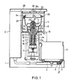
- FIG. 1 is a longitudinal cross section of a coffee maker of an embodiment in accordance with the invention;
- FIG. 2 is an enlarged longitudinal cross section of a brewing case and its surrounding portion of the coffee maker;
- FIG. 3 is a circuit diagram for controlling a motor and a heater in the coffee maker;
- FIG. 4 is a time chart illustrating operations of the motor and the heater;
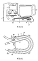
- FIG. 5 is a longitudinal cross section of the lower base section of a coffee maker of a second embodiment; and
- FIG. 6 is a bottom view of a hot water feed mechanism of the coffee maker of the second embodiment.
- Referring now to FIG. 1 of the drawings, a coffee maker embodying the invention comprises a
base 1. A cartridgetype water reservoir 2 is disposed on the left side of thebase 1 and a hot plate 4 is provided on the lower right-hand side of thebase 1, on which plate areceiver 3 for reserving coffee fluid is placed. Anelectric heater 5 and aheating tube 6 are provided on the underside of hot plate 4. Water inreservoir 2 is supplied to theheating tube 6. Anelectric motor 7 of a vertical shaft type is provided betweenreservoir 2 andreceiver 3. Motor 7 is specifically a commutator motor forward and reverse rotated. Aninner shaft 10 for driving acoffee mill 9 described later is vertically secured to an upper end of an upwardly extendedrotational shaft 8 ofmotor 7. A hollowouter shaft 12 for rotating abrewing case 11 described later is fitted withinner shaft 10 for relative rotation.Outer shaft 12 is rotatably mounted on abearing 13 provided with sealing function. Aclutch mechanism 14 is provided for selectively transmitting the rotation ofmotor 7 toouter shaft 12.Clutch mechanism 14 comprises a coil spring wound around a lower endlarge diameter portion 10a ofinner shaft 10 and the lower portion ofouter shaft 12 and the lower end ofcoil spring 15 is secured to lower endlarge diameter portion 10a ofinner shaft 10 by alock pin 16.Clutch mechanism 14 is constructed as a frictional one-way clutch. Therefore,coil spring 15 is wound off againstouter shaft 12 during the forward rotation ofmotor 7 with the result that rotation ofmotor 7 is not transmitted toouter shaft 12, with onlyinner shaft 10 rotated. Whenmotor 7 is reverse rotated, a frictional force causescoil spring 15 to wind up againstouter shaft 12, thereby rotating bothshafts - A
collector case 17 is detachably provided aboveclutch mechanism 14.Collector case 17 has anoutlet 18 formed through the right-hand end of a bottom wall thereof, as viewed in FIGS. 1 and 2.Outlet 18 ofcollector case 17 faces an upper opening ofreceiver 3. Abrewing case 11 utilized for both of milling and brewing operations is enclosed incollector case 17. As seen in FIG. 2, brewingcase 11 has an annular joint 19 formed on the bottom thereof and downwardly extended. An upperend coupling portion 12a ofouter shaft 12 is fitted in with joint 19, thereby holdingbrewing case 11 in position. The inner peripheral surface of joint 19 and the outer peripheral surface ofcoupling portion 12a ofouter shaft 12 are formed so as to have a concave and convex relationship to each other, thereby preventing simultaneous rotation of them. Amill 9 is rotatably mounted inbrewing case 11.Mill 9 has acoupling opening 20a formed under ashaft 20 thereof, to which opening the upper end ofinner shaft 10 is coupled. - Brewing
case 11 has an upper opening covered by alid 21 having acentral opening 21a through which hot water falls down intobrewing case 11. A space having the width of, for example, approximately 0.2 mm is defined betweenbrewing case 11 andlid 21 uniformly along the entire peripheries of them. The space serves as afilter 22.Case 11 has a downwardly tapered inner surface so that the centrifugal force due to rotation causes the coffee fluid or hot water to rise towardfilter 22.Lid 21 has anengagement claw 23 which is engaged with abayonet engagement groove 24 formed in the upper edge portion ofbrewing case 11, thereby fixinglid 21 tobrewing case 11.Collector case 17 also has an upper open end covered by anotherlid 25 having acentral opening 25a through which hot water falls down ontolid 22. A hotwater feed arm 26 is provided abovelid 25 so as to be horizontally pivoted. Hotwater feed arm 26 is communicated toheating pipe 6 and has anoutlet 26a positioned right aboveopening 25a. Hotwater feed arm 26,heating pipe 6 andheater 5 constitute a hotwater feed mechanism 27. Acover 28 covers the upper side ofbase 1 of the coffee maker. - An electrical circuit arrangement of the coffee maker will now be described with reference to FIG. 3. Two switches 31 and 32 are provided for reversing the flow of an electrical current to field
coils armature coil 7c ofmotor 7. Further, aswitch 33 for forward rotation is connected betweenfield coil 7b and apower line 34 and a series circuit of aresistance 35 and aswitch 36 for reverse rotation is connected in parallel withforward rotation switch 33. In the coffee beans milling step, amovable contact 31a ofswitch 31 is engaged with afixed contact 31b thereof and amovable contact 32a ofswitch 32 is engaged with afixed contact 32b thereof. Further,forward rotation switch 33 is turned on for execution of the milling step. Consequently,motor 7 is forward rotated at 10,000 rpm, for example. On the other hand, in the brewing step,movable contact 31a ofswitch 31 is switched to a fixedcontact 31c thereof andmovable contact 32a ofswitch 32 is switched to a fixedcontact 32c. Further,reverse rotation switch 36 is turned on, with the result thatmotor 7 is reverse rotated at 5,000 rpm, for example. The motor revolution in the reverse rotation is decreased to a half of that in the forward rotation becauseresistance 35 reduces the voltage applied tomotor 7. Aheater switch 37 is provided in a power line thereto. Switching operations ofswitches microcomputer 38 serving as control means. After completion of the milling step,microcomputer 38 operates to energize heater 5 (or to turn on heater switch 37) for making of hot water. The timing for reversing the motor rotation is set inmicrocomputer 38 so thatmotor 7 is reverse rotated (or switch 36 is turned on) when substantially the entire milled coffee beans is permeated with the hot water fed intobrewing case 11. In the embodiment, the timing for reversing the motor rotation is determined by a timer which starts the time-counting operation simultaneously with the start of energization ofheater 5.Motor 7 is reverse rotated at the time when the timer accumulated period reaches a predetermined period previously obtained by an experiment. FIG. 4 illustrates the relationship between the directions of motor rotation and an energization period ofheater 5. - The operation of the coffee maker will now be described. First, a certain amount of water is supplied to
reservoir 2 and a corresponding amount of coffee beans is contained inbrewing case 11,reservoir 2 andbrewing case 11 being set as shown in FIG. 1. Then, when a switch (not shown) is operated in order that the milling step is initiated,microcomputer 38 operates so thatmovable contact 31a ofswitch 31 is engaged withfixed contact 31b and so thatmovable contact 32a ofswitch 32 is engaged withfixed contact 32b.Microcomputer 38 further operates to turn on forward rotation switch 33 so thatmotor 7 forward rotates at 10,000 rpm, for example. Consequently,mill 9 is driven to mill the coffee beans inbrewing case 11. In the milling step,motor 7 rotates in the same direction thatcoil spring 15 ofclutch mechanism 14 is wound off againstouter shaft 12. Accordingly, rotation ofmotor 7 is not transmitted toouter shaft 12, with the result thatbrewing case 11 is stationary in the milling step. - The above-described milling operation is executed for a predetermined period, for example, for 30 to 40 seconds. Then,
microcomputer 38 operates to turn off forward rotation switch 33 to temporallydeenergize motor 7. Subsequently,heater switch 37 is turned on so thatheater 5 is energized, whereby the water fed toheating pipe 6 fromreservoir 2 is sequentially heated, thereby obtaining hot water. The boiling pressure raises the hot water to hotwater feed arm 26 sequentially. The hot water fed to feedarm 26 is then fed intobrewing case 11 throughoutlets respective lids brewing case 11 is wetted with the hot water,microcomputer 38 operates to engagemovable contact 31a ofswitch 31 with fixedcontact 31c and to engagemovable contact 32a ofswitch 32 with fixedcontact 32c.Microcomputer 38 further operates to turn onreverse rotation switch 36. Consequently,motor 7 reverse rotates at 5,000 rpm, for example. Sincemotor 7 rotates in the direction thatcoil spring 15 ofclutch mechanism 14 is wound up,coil spring 15 is wound up against the outer periphery ofouter shaft 12, whereby rotation ofmotor 7 is transmitted toouter shaft 12 as well asinner shaft 10. Inner andouter shafts brewing case 11 is rotated at high speed withmill 9. Since some hot water is already fed inbrewing case 11 before rotation thereof, the hot water uniformly permeates the entire milled coffee beans inbrewing case 11, thereby balancingbrewing case 11. Consequently, even when brewingcase 11 starts rotating, almost no oscillation ofbrewing case 11 occurs, which contributes to stabilize the motor rotation in the rise period. Upon rotation ofbrewing case 11, a centrifugal force due to rotation causes milled coffee beans A inbrewing case 11 to uniformly disperse to the peripheral wall side, as shown in FIG. 2. Consequently, milled coffee beans A uniformly sticks to the peripheral wall inner surface with the result that a uniform layer of milled coffee beans A is formed along the peripheral wall inner surface. In this state, the hot water is discharged fromfeed arm 26 toward the inner central portion ofbrewing case 11 to be thereby received bymill 9 and inner bottom ofbrewing case 11. Rotation ofmill 9 shakes off the hot water received by the mill in the direction that the centrifugal force acts and consequently, the hot water is dispersed around to thereby permeate coffee ground A from the inner peripheral side. Furthermore, the centrifugal force due to rotation ofbrewing case 11 causes the hot water received by the inner bottom thereof to permeate milled coffee beans A through the brewing case inner bottom surface. The hot water having thus permeated milled coffee beans A passes therethrough relatively promptly owing to the centrifugal force with coffee ingredients extracted and reaches the inner surface of the brewing case peripheral wall. The hot water containing coffee ingredients is further caused to rise along the tapered inner peripheral wall surface and disperse around fromfilter 22 to be thereby received by the inner peripheral wall ofcollector case 17. The coffee fluid thus received by the inner peripheral wall ofcollector case 17 flows downward along the wall, falling downward fromoutlet 18 intoreceiver 3. Since the centrifugal force due to rotation ofbrewing case 11 causes the hot water to pass through milled coffee beans A relatively promptly, only essential fragrant ingredients are extracted and those degrading the flavor of coffee are not extracted, thereby improving the coffee flavor. - As obvious from the foregoing description, brewing
case 11 is rotated after the hot water feed to the brewing case is initiated. Accordingly, brewingcase 11 is stationary at an initial stage of the hot water feed and the hot water uniformly permeates the entire milled coffee beans inbrewing case 11, with the result thatbrewing case 11 is balanced. Consequently, rotation ofbrewing case 7 may be stabilized from the first, thereby reducing oscillation due to the unbalanced state of brewingcase 11 and reducing the noise. Additionally, since the hot water feed to brewingcase 11 is automatically performed, coffee may be easily made without trouble of a user. - Should the hot water feed be initiated before the start of rotation of
brewing case 11, it would be considered that the noise due to oscillation ofbrewing case 11 is reduced. However, in order to achieve remarkable noise reduction effect,motor 7 is preferably started to drive brewingcase 11 after the hot water feed by hotwater feed mechanism 27 is initiated such that the entire milled coffee beans inbrewing case 11 is wetted with the hot water. The reason for this is that should the milled coffee beans include wet and unwet parts, the unwet milled coffee beans adheres to the wet milled coffee beans into lumps of milled coffee beans, which unbalances the brewing case. Furthermore,motor 7 may be driven to rotatebrewing case 11 after the hot water is fed tobrewing case 11 to be reserved therein. When the hot water is reserved in the brewing case, the entire milled coffee beans is necessarily permeated with the hot water such that the brewing case keeps its balance or balanced. -
Mill 9 is rotatably mounted inbrewing case 11 andclutch mechanism 14 is provided for selectively transmitting rotation ofmotor 7 tobrewing case 11 andmill 9. Consequently, a single brewing case may be utilized for both of the milling and brewing operations and a single motor as a drive source may be employed for drivingmill 9 andbrewing case 11. Consequently, the invention provides a coffee maker simple in construction and compact in size and the coffee maker of the invention is advantageous when applied to a house hold coffee maker. -
Clutch mechanism 14 has the construction of a one-way clutch andmotor 7 may be forward and reverse rotated. Consequently,mill 9 andbrewing case 11 may be selectively rotated. Further, since the construction ofclutch mechanism 14 is simplified, the production cost of the coffee maker may be reduced. Additionally, although the one-way clutch comprisescoil spring 15 in the foregoing embodiment, a sprag clutch or other type one-way clutches may be employed. Moreover, the clutch mechanism is not limited to the one-way clutches. For example, an electromagnetic clutch, a conical friction clutch, a disc clutch or the like may be employed. In each of these clutches, the clutch is operated before the start of the brewing step so that brewing case is driven. The motor is not needed to change its direction of rotation. - Since the motor is driven in the brewing step at the speed lower than that in the milling step, the noise due to oscillation may be reduced in the brewing step. Although the motor speed is decreased in the brewing step, a sufficient peripheral speed of
brewing case 11 may be ensured since the outer diameter of the brewing case is larger than that ofmill 9, thereby ensuring a sufficient centrifugal force for the coffee brewing. - Although the rotation timing of
brewing case 11 is determined by the timer which starts the time-counting operation simultaneously with the start of energization ofheater 5, detecting means may be provided for detecting the rotation timing ofbrewing case 11, instead. When detecting the rotation timing ofbrewing case 11, the detecting means generates a detection signal, which is supplied tomicrocomputer 38. Upon receipt of the detection signal,microcomputer 38 operates to drive brewingcase 11. More specifically, athermistor 39 may be employed as such detecting means, as shown in FIGS. 5 and 6.Thermistor 39 is disposed on aportion 6a ofheating tube 6 at the reservoir or water inlet side.Thermistor 39 detects the temperature ofheating tube 6 to thereby generate a detection signal, which is supplied tomicrocomputer 38. When the temperature detected bythermistor 39 reaches a predetermined temperature at which the hot water feed to brewingcase 11 is initiated,microcomputer 38 operates so thatmotor 7 is reverse rotated to drive brewingcase 11. Provision of the detecting means such asthermistor 35 is advantageous in that the rotation timing ofbrewing case 11 may be accurately determined independent of the temperature of water inreservoir 2. Alternatively,motor 7 may be reverse rotated with a predetermined delay period when the temperature detected bythermistor 39 reaches the predetermined temperature. The reason for the disposition ofthermistor 39 onportion 6a ofheating tube 6 at the reservoir side is thatthermistor 39 also serves to detect completion of hot water feed to brewingcase 11. More specifically, when the water inreservoir 2 is all fed and theheating tube 6 is dried up, the temperature of heating tube is rapidly increased. The rapid temperature increase is detected bythermistor 39, thereby accurately determining the completion of hot water feed.Heater 5 may be deenergized upon completion of hot water feed. The position ofthermistor 39 is not limited to that described above. It may be disposed on aportion 6b ofheating tube 6 at the outlet side or on hotwater feed arm 26. - Instead of
thermistor 39, a weight sensor may be provided for measuring the weight ofbrewing case 11. The rotation timing ofbrewing case 11 may be determined based on changes of weight ofbrewing case 11 measured by weight sensor. Furthermore, a flowmeter may be mounted on hotwater feed arm 26 for detecting the flow rate of hot water and the rotation timing ofbrewing case 11 may be determined based on changes of the detected flow rate. - A number of small perforations may be formed in the entire peripheral wall of
brewing case 11 so as to serve as the filter. Additionally, the coupling structure between inner andouter shafts mill 9 andbrewing case 11 may be changed. - The foregoing disclosure and drawings are merely illustrative of the principles of the present invention and are not to be interpreted in a limiting sense. The only limitation is to be determined from the scope of the appended claims.
Claims (10)
Applications Claiming Priority (8)
| Application Number | Priority Date | Filing Date | Title |
|---|---|---|---|
| JP278295/88 | 1988-11-02 | ||
| JP63278296A JP2731186B2 (en) | 1988-11-02 | 1988-11-02 | Beverage extractor |
| JP63278295A JPH082335B2 (en) | 1988-11-02 | 1988-11-02 | Coffee making machine |
| JP278296/88 | 1988-11-02 | ||
| JP8169/89 | 1989-01-17 | ||
| JP1008169A JPH02189115A (en) | 1989-01-17 | 1989-01-17 | Coffee extractor |
| JP1035660A JP2731213B2 (en) | 1989-02-15 | 1989-02-15 | Coffee extractor |
| JP35660/89 | 1989-02-15 |
Publications (2)
| Publication Number | Publication Date |
|---|---|
| EP0367600A1 true EP0367600A1 (en) | 1990-05-09 |
| EP0367600B1 EP0367600B1 (en) | 1993-05-12 |
Family
ID=27454890
Family Applications (1)
| Application Number | Title | Priority Date | Filing Date |
|---|---|---|---|
| EP89311341A Expired - Lifetime EP0367600B1 (en) | 1988-11-02 | 1989-11-02 | Centrifugal brewing type coffee maker |
Country Status (3)
| Country | Link |
|---|---|
| US (1) | US4962693A (en) |
| EP (1) | EP0367600B1 (en) |
| DE (1) | DE68906509T2 (en) |
Cited By (27)
| Publication number | Priority date | Publication date | Assignee | Title |
|---|---|---|---|---|
| FR2686007A1 (en) * | 1992-01-10 | 1993-07-16 | Seb Sa | Combined machine for making hot drinks, e.g. a combined coffee-maker |
| EP2000062A1 (en) | 2007-06-05 | 2008-12-10 | Nestec S.A. | Method for preparing a beverage or liquid food and system using brewing centrifugal force |
| WO2008148650A1 (en) * | 2007-06-05 | 2008-12-11 | Nestec S.A. | Single-use capsule for preparing a food liquid by centrifugation |
| WO2008148834A1 (en) | 2007-06-05 | 2008-12-11 | Nestec S.A. | Capsule and method for preparing a food liquid by centrifugation |
| WO2009106598A1 (en) * | 2008-02-29 | 2009-09-03 | Nestec S.A. | Method and system for preparing a liquid extract from a cell using centrifugal forces |
| WO2010026053A1 (en) * | 2008-09-02 | 2010-03-11 | Nestec S.A. | Controlled beverage production device using centrifugal forces |
| EP2208449A2 (en) | 2007-06-05 | 2010-07-21 | Nestec S.A. | Capsule for preparing a beverage or liquid food and system using brewing centrifugal force |
| JP2010528738A (en) * | 2007-06-05 | 2010-08-26 | ネステク ソシエテ アノニム | Method and apparatus compatible with a method for producing a food liquid contained in a capsule by centrifugation |
| JP2012510323A (en) * | 2008-12-03 | 2012-05-10 | ネステク ソシエテ アノニム | Capsules for the preparation of beverages by centrifugation |
| CN103040361A (en) * | 2013-01-08 | 2013-04-17 | 周林斌 | Bean grinding coffee maker and method thereof |
| US8431175B2 (en) | 2007-06-05 | 2013-04-30 | Nestec S.A. | Method for preparing a beverage or food liquid and system using brewing centrifugal force |
| CN103190832A (en) * | 2013-01-08 | 2013-07-10 | 周林斌 | Coffee pot filtering device and method thereof |
| CN103284606A (en) * | 2012-02-27 | 2013-09-11 | 美的集团股份有限公司 | Coffee bean grinding type coffee machine |
| EP2807962A1 (en) * | 2013-05-29 | 2014-12-03 | BSH Bosch und Siemens Hausgeräte GmbH | Fully automatic coffee maker with a centrifuge chamber |
| US8919242B2 (en) | 2008-09-02 | 2014-12-30 | Nestec S.A. | Method for preparing a food liquid contained in a capsule by centrifugation and system adapted for such method |
| US9095236B2 (en) | 2008-12-09 | 2015-08-04 | Nestec S.A. | Liquid food preparation system for preparing a liquid food by centrifugation |
| US9162815B2 (en) | 2009-08-19 | 2015-10-20 | Nestec S.A. | Capsule for the preparation of a coffee extract having a structure facilitating perforation for injection of water |
| CN105686651A (en) * | 2015-04-28 | 2016-06-22 | 周林斌 | Working method of bean grinding coffeepot |
| US9545121B2 (en) | 2008-12-09 | 2017-01-17 | Nestec S.A. | Capsule for preparing a beverage by centrifugation in a beverage preparation device and device adapted therefore |
| US9668604B2 (en) | 2009-08-28 | 2017-06-06 | Nestec S.A. | Capsule system for the preparation of beverages by centrifugation |
| CN107811514A (en) * | 2016-09-14 | 2018-03-20 | 广东美的生活电器制造有限公司 | Coffee machine |
| CN107811511A (en) * | 2016-09-14 | 2018-03-20 | 广东美的生活电器制造有限公司 | Coffee machine |
| CN107811513A (en) * | 2016-09-14 | 2018-03-20 | 广东美的生活电器制造有限公司 | Coffee machine and coffee preparation method |
| WO2018049789A1 (en) * | 2016-09-14 | 2018-03-22 | 广东美的生活电器制造有限公司 | Coffee maker and preparation method therefor |
| CN107874621A (en) * | 2016-09-29 | 2018-04-06 | 广东美的生活电器制造有限公司 | Coffee machine filter screen and coffee machine |
| US10806293B2 (en) | 2016-09-29 | 2020-10-20 | Guangdong Midea Consumer Electrics Manufacturing Co., Ltd. | Coffee machine screen and coffee machine |
| WO2022179744A1 (en) * | 2021-02-26 | 2022-09-01 | Ivan Mallinowski | Method and device for producing a suspension |
Families Citing this family (33)
| Publication number | Priority date | Publication date | Assignee | Title |
|---|---|---|---|---|
| US5265517A (en) * | 1991-10-09 | 1993-11-30 | Industria Columbiana De Electronicos Y Electrodomesticos, Incelt S.A. Of Carrera | Method and apparatus for brewing coffee |
| US5566605A (en) * | 1993-11-09 | 1996-10-22 | Seb S.A. | Centrifugal type extraction cell having a deformable sealing joint for a hot beverage preparation machine |
| DE4418139C1 (en) | 1994-05-25 | 1995-02-09 | Samaro Eng & Handel | Mill work for coffee mills (coffee grinders) |
| US5463932A (en) * | 1995-01-19 | 1995-11-07 | Olson; Allen W. | Coffee maker |
| US5957035A (en) * | 1997-10-10 | 1999-09-28 | Richter; Walter M. | Swirling oscillation coffee maker |
| US5992299A (en) * | 1998-05-21 | 1999-11-30 | Silver Plan Industrial Limited | Coffee makers |
| US6227102B1 (en) * | 1999-04-27 | 2001-05-08 | John C. K. Sham | Automatic coffee maker with grinder |
| US7640843B2 (en) * | 2003-01-24 | 2010-01-05 | Kraft Foods R & D, Inc. | Cartridge and method for the preparation of beverages |
| US6968775B2 (en) * | 2003-05-19 | 2005-11-29 | Aroma Fresh, Llc | Coffee brewer |
| US7340991B2 (en) * | 2003-05-19 | 2008-03-11 | Aroma Fresh, Llc | Coffee brewer |
| CN101217904B (en) * | 2005-04-22 | 2011-03-09 | 美嘉伦亚洲有限公司 | Device for preparing coffee |
| US7581490B2 (en) * | 2005-04-28 | 2009-09-01 | Applica Consumer Products, Inc. | Coffeemaker with water feed velocity decreaser |
| WO2007041954A1 (en) * | 2005-10-11 | 2007-04-19 | Zhiping Li | Coffee maker |
| US20100212509A1 (en) * | 2009-02-20 | 2010-08-26 | Pao-Wu Tien | Safety and guide type brewing kettle |
| US8658232B2 (en) * | 2009-08-28 | 2014-02-25 | Nestec S.A. | Capsule system for the preparation of beverages by centrifugation |
| JP2011160800A (en) * | 2010-01-15 | 2011-08-25 | Suntory Holdings Ltd | Method for producing coffee extract |
| US8573115B2 (en) * | 2010-11-15 | 2013-11-05 | Conair Corporation | Brewed beverage appliance and method |
| US9066623B2 (en) * | 2010-11-15 | 2015-06-30 | Conair Corporation | Brewed beverage appliance and method |
| CN105686664B (en) * | 2011-01-17 | 2019-02-12 | 三得利控股株式会社 | Beverage extracting device |
| USD677510S1 (en) | 2011-06-16 | 2013-03-12 | Calphalon Corporation | Coffee maker |
| US10238230B2 (en) * | 2011-08-09 | 2019-03-26 | Nestec S.A. | Centrifugal brewing machine with flow collecting assembly |
| RU2631840C2 (en) * | 2012-12-06 | 2017-09-26 | Нестек С.А. | Device for preparing beverage by centrifugation |
| JP6289130B2 (en) * | 2014-01-31 | 2018-03-07 | シャープ株式会社 | Beverage production equipment |
| JP6214411B2 (en) * | 2014-01-31 | 2017-10-18 | シャープ株式会社 | Beverage production equipment |
| US20150327718A1 (en) | 2014-02-14 | 2015-11-19 | Remington Designs, Llc | Apparatuses and methods for solute extraction |
| EP3217848B1 (en) * | 2014-11-14 | 2018-06-13 | Koninklijke Philips N.V. | Coffee processing apparatus and method |
| CN105266657B (en) * | 2015-11-09 | 2017-12-22 | 广东新宝电器股份有限公司 | Coffee machine and filtering drainage cylinder |
| US10004354B2 (en) * | 2015-12-30 | 2018-06-26 | Conair Corporation | Coffee making appliance for brewing coffee |
| US10542839B2 (en) | 2015-12-30 | 2020-01-28 | Conair Corporation | Coffee making appliance |
| KR101716316B1 (en) | 2016-05-25 | 2017-03-14 | 주식회사 태성트레이딩 | Coffee Brewing Machine Using Centrifugal Force |
| USD833792S1 (en) | 2017-02-14 | 2018-11-20 | Hamilton Beach Brands, Inc. | Coffeemaker |
| EP3675693A4 (en) * | 2017-08-31 | 2021-08-04 | Innovative Brewing, LLC | Devices and methods for brewing beverages |
| EP4366592A1 (en) * | 2022-09-30 | 2024-05-15 | Ivan Mallinowski | Method and device for producing a suspension |
Citations (6)
| Publication number | Priority date | Publication date | Assignee | Title |
|---|---|---|---|---|
| US1789334A (en) * | 1929-05-21 | 1931-01-20 | Leonard H Englund | Method and apparatus for making infusions |
| US2149270A (en) * | 1933-02-16 | 1939-03-07 | Burgess Louis | Coffee maker |
| FR2132310A1 (en) * | 1971-04-03 | 1972-11-17 | Hultsch Gunther | |
| DE2151920A1 (en) * | 1971-04-03 | 1973-04-26 | Guenther Hultsch | COFFEE MACHINE WITH GRINDING DEVICE |
| DE3137651A1 (en) * | 1981-09-22 | 1983-04-14 | Bosch-Siemens Hausgeräte GmbH, 7000 Stuttgart | Outlet for a beverage-making apparatus |
| EP0280794A1 (en) * | 1987-03-03 | 1988-09-07 | Animo B.V. | Process and apparatus for brewing hot beverages |
Family Cites Families (3)
| Publication number | Priority date | Publication date | Assignee | Title |
|---|---|---|---|---|
| GB887212A (en) * | 1957-06-15 | 1962-01-17 | Philips Nv | Improvements in centrifuges for producing coffee filtrate |
| US4196658A (en) * | 1977-11-30 | 1980-04-08 | Tokyo Shibaura Denki Kabushiki Kaisha | Coffee-pot and coffee-mill combination |
| AT391257B (en) * | 1981-09-22 | 1990-09-10 | Bosch Siemens Hausgeraete | ELECTRIC COFFEE MACHINE WITH A CENTRIFUGAL FILTER |
-
1989
- 1989-11-01 US US07/429,980 patent/US4962693A/en not_active Expired - Fee Related
- 1989-11-02 DE DE89311341T patent/DE68906509T2/en not_active Expired - Fee Related
- 1989-11-02 EP EP89311341A patent/EP0367600B1/en not_active Expired - Lifetime
Patent Citations (6)
| Publication number | Priority date | Publication date | Assignee | Title |
|---|---|---|---|---|
| US1789334A (en) * | 1929-05-21 | 1931-01-20 | Leonard H Englund | Method and apparatus for making infusions |
| US2149270A (en) * | 1933-02-16 | 1939-03-07 | Burgess Louis | Coffee maker |
| FR2132310A1 (en) * | 1971-04-03 | 1972-11-17 | Hultsch Gunther | |
| DE2151920A1 (en) * | 1971-04-03 | 1973-04-26 | Guenther Hultsch | COFFEE MACHINE WITH GRINDING DEVICE |
| DE3137651A1 (en) * | 1981-09-22 | 1983-04-14 | Bosch-Siemens Hausgeräte GmbH, 7000 Stuttgart | Outlet for a beverage-making apparatus |
| EP0280794A1 (en) * | 1987-03-03 | 1988-09-07 | Animo B.V. | Process and apparatus for brewing hot beverages |
Cited By (59)
| Publication number | Priority date | Publication date | Assignee | Title |
|---|---|---|---|---|
| FR2686007A1 (en) * | 1992-01-10 | 1993-07-16 | Seb Sa | Combined machine for making hot drinks, e.g. a combined coffee-maker |
| EP2316310A1 (en) | 2007-06-05 | 2011-05-04 | Nestec S.A. | System and method for preparing a food liquid from a food substance contained in a receptacle by centrifugation |
| US8813634B2 (en) | 2007-06-05 | 2014-08-26 | Nestec S.A. | Capsule for preparing a beverage or liquid food and system using brewing centrifugal force |
| EP2316309A1 (en) | 2007-06-05 | 2011-05-04 | Nestec S.A. | Device and method for preparing a food liquid by centrifugation |
| US9226611B2 (en) | 2007-06-05 | 2016-01-05 | Nestec S.A. | Capsule system, device and method for preparing a food liquid contained in a receptacle by centrifugation |
| US9968111B2 (en) | 2007-06-05 | 2018-05-15 | Nestec S.A. | Capsule and method for preparing a food liquid by centrifugation |
| EP2208449A2 (en) | 2007-06-05 | 2010-07-21 | Nestec S.A. | Capsule for preparing a beverage or liquid food and system using brewing centrifugal force |
| EP2210538A2 (en) | 2007-06-05 | 2010-07-28 | Nestec S.A. | Capsule for preparing a beverage or liquid food and system using brewing centrifugal force |
| EP2210539A2 (en) | 2007-06-05 | 2010-07-28 | Nestec S.A. | Device and system for preparing a beverage using brewing centrifugal force |
| JP2010528738A (en) * | 2007-06-05 | 2010-08-26 | ネステク ソシエテ アノニム | Method and apparatus compatible with a method for producing a food liquid contained in a capsule by centrifugation |
| EP2000062A1 (en) | 2007-06-05 | 2008-12-10 | Nestec S.A. | Method for preparing a beverage or liquid food and system using brewing centrifugal force |
| WO2008148834A1 (en) | 2007-06-05 | 2008-12-11 | Nestec S.A. | Capsule and method for preparing a food liquid by centrifugation |
| WO2008148650A1 (en) * | 2007-06-05 | 2008-12-11 | Nestec S.A. | Single-use capsule for preparing a food liquid by centrifugation |
| JP2010528737A (en) * | 2007-06-05 | 2010-08-26 | ネステク ソシエテ アノニム | Capsule system, apparatus, and method for producing a food liquid to be contained in a container by centrifugation |
| US9743799B2 (en) | 2007-06-05 | 2017-08-29 | Nestec S.A. | Method for preparing a beverage or liquid food and system using brewing centrifugal force |
| CN101687591B (en) * | 2007-06-05 | 2012-06-20 | 雀巢产品技术援助有限公司 | Single-use capsule for preparing a food liquid by centrifugation |
| RU2457994C2 (en) * | 2007-06-05 | 2012-08-10 | Нестек С.А. | Throwaway capsule for food fluid production by centrifugation |
| US8409646B2 (en) | 2007-06-05 | 2013-04-02 | Nestec S.A. | Single-use capsule for preparing a food liquid by centrifugation |
| US9731892B2 (en) | 2007-06-05 | 2017-08-15 | Nestec S.A. | Capsule and method for preparing a food liquid by centrifugation |
| US8431175B2 (en) | 2007-06-05 | 2013-04-30 | Nestec S.A. | Method for preparing a beverage or food liquid and system using brewing centrifugal force |
| US9603479B2 (en) | 2007-06-05 | 2017-03-28 | Nestec S.A. | Capsule for preparing a beverage or liquid food and system using brewing centrifugal force |
| US9434532B2 (en) | 2007-06-05 | 2016-09-06 | Nestec S.A. | Capsule for preparing a beverage or food liquid and system using brewing centrifugal force |
| WO2009106598A1 (en) * | 2008-02-29 | 2009-09-03 | Nestec S.A. | Method and system for preparing a liquid extract from a cell using centrifugal forces |
| CN101959446B (en) * | 2008-02-29 | 2014-04-16 | 雀巢产品技术援助有限公司 | Method and system for preparing a liquid extract from a cell using centrifugal forces |
| JP2012501199A (en) * | 2008-09-02 | 2012-01-19 | ネステク ソシエテ アノニム | Controlled beverage production equipment using centrifugal force |
| CN102196753B (en) * | 2008-09-02 | 2013-07-31 | 雀巢产品技术援助有限公司 | Controlled beverage production device using centrifugal forces |
| RU2492788C2 (en) * | 2008-09-02 | 2013-09-20 | Нестек С.А. | Controllable device for preparation of beverages using centrifugal forces |
| WO2010026053A1 (en) * | 2008-09-02 | 2010-03-11 | Nestec S.A. | Controlled beverage production device using centrifugal forces |
| US8919242B2 (en) | 2008-09-02 | 2014-12-30 | Nestec S.A. | Method for preparing a food liquid contained in a capsule by centrifugation and system adapted for such method |
| AU2009289682B2 (en) * | 2008-09-02 | 2016-06-09 | Société des Produits Nestlé S.A. | Controlled beverage production device using centrifugal forces |
| US8512784B2 (en) | 2008-09-02 | 2013-08-20 | Nestec S.A. | Method and device for controlled beverage production using centrifugal forces |
| JP2012510323A (en) * | 2008-12-03 | 2012-05-10 | ネステク ソシエテ アノニム | Capsules for the preparation of beverages by centrifugation |
| US8962048B2 (en) | 2008-12-03 | 2015-02-24 | Nestec S.A. | Capsule for the preparation of a beverage by centrifugation |
| US9095236B2 (en) | 2008-12-09 | 2015-08-04 | Nestec S.A. | Liquid food preparation system for preparing a liquid food by centrifugation |
| US9545121B2 (en) | 2008-12-09 | 2017-01-17 | Nestec S.A. | Capsule for preparing a beverage by centrifugation in a beverage preparation device and device adapted therefore |
| US9162815B2 (en) | 2009-08-19 | 2015-10-20 | Nestec S.A. | Capsule for the preparation of a coffee extract having a structure facilitating perforation for injection of water |
| US9668604B2 (en) | 2009-08-28 | 2017-06-06 | Nestec S.A. | Capsule system for the preparation of beverages by centrifugation |
| CN103284606B (en) * | 2012-02-27 | 2016-04-20 | 美的集团股份有限公司 | A kind of mill beans formula coffee machine |
| CN103284606A (en) * | 2012-02-27 | 2013-09-11 | 美的集团股份有限公司 | Coffee bean grinding type coffee machine |
| CN103190832A (en) * | 2013-01-08 | 2013-07-10 | 周林斌 | Coffee pot filtering device and method thereof |
| CN103040361A (en) * | 2013-01-08 | 2013-04-17 | 周林斌 | Bean grinding coffee maker and method thereof |
| CN103190832B (en) * | 2013-01-08 | 2015-08-26 | 周林斌 | A kind of coffeepot filter device and method thereof |
| EP2807962A1 (en) * | 2013-05-29 | 2014-12-03 | BSH Bosch und Siemens Hausgeräte GmbH | Fully automatic coffee maker with a centrifuge chamber |
| CN105686652A (en) * | 2015-04-28 | 2016-06-22 | 周林斌 | Bean grinding coffeepot |
| CN105686657A (en) * | 2015-04-28 | 2016-06-22 | 周林斌 | Bean smashing and grinding coffee maker |
| CN105686651A (en) * | 2015-04-28 | 2016-06-22 | 周林斌 | Working method of bean grinding coffeepot |
| CN105686657B (en) * | 2015-04-28 | 2018-09-07 | 周林斌 | The coffee pot of pulverising mill beans |
| WO2018049789A1 (en) * | 2016-09-14 | 2018-03-22 | 广东美的生活电器制造有限公司 | Coffee maker and preparation method therefor |
| CN107811513A (en) * | 2016-09-14 | 2018-03-20 | 广东美的生活电器制造有限公司 | Coffee machine and coffee preparation method |
| CN107811511A (en) * | 2016-09-14 | 2018-03-20 | 广东美的生活电器制造有限公司 | Coffee machine |
| CN107811514A (en) * | 2016-09-14 | 2018-03-20 | 广东美的生活电器制造有限公司 | Coffee machine |
| CN107811513B (en) * | 2016-09-14 | 2019-09-20 | 广东美的生活电器制造有限公司 | Coffee machine and coffee preparation method |
| CN107811514B (en) * | 2016-09-14 | 2019-11-08 | 广东美的生活电器制造有限公司 | Coffee machine |
| CN107811511B (en) * | 2016-09-14 | 2019-11-08 | 广东美的生活电器制造有限公司 | Coffee machine |
| US10694885B2 (en) | 2016-09-14 | 2020-06-30 | Guangdong Midea Consumer Electrics Manufacturing Co., Ltd. | Coffee maker and coffee preparation method |
| CN107874621A (en) * | 2016-09-29 | 2018-04-06 | 广东美的生活电器制造有限公司 | Coffee machine filter screen and coffee machine |
| CN107874621B (en) * | 2016-09-29 | 2019-12-06 | 广东美的生活电器制造有限公司 | Coffee machine filter screen and coffee machine |
| US10806293B2 (en) | 2016-09-29 | 2020-10-20 | Guangdong Midea Consumer Electrics Manufacturing Co., Ltd. | Coffee machine screen and coffee machine |
| WO2022179744A1 (en) * | 2021-02-26 | 2022-09-01 | Ivan Mallinowski | Method and device for producing a suspension |
Also Published As
| Publication number | Publication date |
|---|---|
| US4962693A (en) | 1990-10-16 |
| EP0367600B1 (en) | 1993-05-12 |
| DE68906509D1 (en) | 1993-06-17 |
| DE68906509T2 (en) | 1993-09-30 |
Similar Documents
| Publication | Publication Date | Title |
|---|---|---|
| EP0367600B1 (en) | Centrifugal brewing type coffee maker | |
| US4802407A (en) | Automatic electric household appliance for making cheese and by-products thereof | |
| US5463932A (en) | Coffee maker | |
| EP0354670A1 (en) | Auto-off coffee brewing system | |
| US4545296A (en) | Centrifugal apparatus for making coffee | |
| US5992299A (en) | Coffee makers | |
| JP2731213B2 (en) | Coffee extractor | |
| JPH08107826A (en) | Coffee boiler | |
| KR920004262B1 (en) | Coffee maker | |
| JPH0710679Y2 (en) | Coffee making machine | |
| JP3052222B2 (en) | Coffee kettle | |
| JPH082335B2 (en) | Coffee making machine | |
| JPH0710676Y2 (en) | Coffee extractor | |
| JP3997655B2 (en) | Rice mill | |
| JPH0632035Y2 (en) | Beverage making machine | |
| JPS631839Y2 (en) | ||
| CN113633174B (en) | Automatic milk brewing machine | |
| CN212728664U (en) | Portable milk tea cup | |
| JPH0710677Y2 (en) | Coffee extractor | |
| JP2000051102A (en) | Coffee maker | |
| JPS631833Y2 (en) | ||
| JPS631834Y2 (en) | ||
| JPS631835Y2 (en) | ||
| JPS631836Y2 (en) | ||
| JPS6314640Y2 (en) |
Legal Events
| Date | Code | Title | Description |
|---|---|---|---|
| PUAI | Public reference made under article 153(3) epc to a published international application that has entered the european phase |
Free format text: ORIGINAL CODE: 0009012 |
|
| 17P | Request for examination filed |
Effective date: 19891116 |
|
| AK | Designated contracting states |
Kind code of ref document: A1 Designated state(s): DE FR GB IT NL |
|
| 17Q | First examination report despatched |
Effective date: 19911007 |
|
| GRAA | (expected) grant |
Free format text: ORIGINAL CODE: 0009210 |
|
| AK | Designated contracting states |
Kind code of ref document: B1 Designated state(s): DE FR GB IT NL |
|
| ITF | It: translation for a ep patent filed |
Owner name: BUGNION S.P.A. |
|
| REF | Corresponds to: |
Ref document number: 68906509 Country of ref document: DE Date of ref document: 19930617 |
|
| ET | Fr: translation filed | ||
| REG | Reference to a national code |
Ref country code: GB Ref legal event code: 746 Effective date: 19980917 |
|
| PGFP | Annual fee paid to national office [announced via postgrant information from national office to epo] |
Ref country code: GB Payment date: 19981106 Year of fee payment: 10 Ref country code: DE Payment date: 19981106 Year of fee payment: 10 |
|
| PGFP | Annual fee paid to national office [announced via postgrant information from national office to epo] |
Ref country code: FR Payment date: 19981110 Year of fee payment: 10 |
|
| PGFP | Annual fee paid to national office [announced via postgrant information from national office to epo] |
Ref country code: NL Payment date: 19981126 Year of fee payment: 10 |
|
| REG | Reference to a national code |
Ref country code: FR Ref legal event code: D6 |
|
| PG25 | Lapsed in a contracting state [announced via postgrant information from national office to epo] |
Ref country code: GB Free format text: LAPSE BECAUSE OF NON-PAYMENT OF DUE FEES Effective date: 19991102 |
|
| PG25 | Lapsed in a contracting state [announced via postgrant information from national office to epo] |
Ref country code: NL Free format text: LAPSE BECAUSE OF NON-PAYMENT OF DUE FEES Effective date: 20000601 |
|
| GBPC | Gb: european patent ceased through non-payment of renewal fee |
Effective date: 19991102 |
|
| PG25 | Lapsed in a contracting state [announced via postgrant information from national office to epo] |
Ref country code: FR Free format text: LAPSE BECAUSE OF NON-PAYMENT OF DUE FEES Effective date: 20000731 |
|
| NLV4 | Nl: lapsed or anulled due to non-payment of the annual fee |
Effective date: 20000601 |
|
| PG25 | Lapsed in a contracting state [announced via postgrant information from national office to epo] |
Ref country code: DE Free format text: LAPSE BECAUSE OF NON-PAYMENT OF DUE FEES Effective date: 20000901 |
|
| REG | Reference to a national code |
Ref country code: FR Ref legal event code: ST |
|
| PG25 | Lapsed in a contracting state [announced via postgrant information from national office to epo] |
Ref country code: IT Free format text: LAPSE BECAUSE OF NON-PAYMENT OF DUE FEES;WARNING: LAPSES OF ITALIAN PATENTS WITH EFFECTIVE DATE BEFORE 2007 MAY HAVE OCCURRED AT ANY TIME BEFORE 2007. THE CORRECT EFFECTIVE DATE MAY BE DIFFERENT FROM THE ONE RECORDED. Effective date: 20051102 |
|
| PLBE | No opposition filed within time limit |
Free format text: ORIGINAL CODE: 0009261 |
|
| STAA | Information on the status of an ep patent application or granted ep patent |
Free format text: STATUS: NO OPPOSITION FILED WITHIN TIME LIMIT |