EP0263719A1 - Measuring mass flow rates of fluid flows - Google Patents
Measuring mass flow rates of fluid flows Download PDFInfo
- Publication number
- EP0263719A1 EP0263719A1 EP87308967A EP87308967A EP0263719A1 EP 0263719 A1 EP0263719 A1 EP 0263719A1 EP 87308967 A EP87308967 A EP 87308967A EP 87308967 A EP87308967 A EP 87308967A EP 0263719 A1 EP0263719 A1 EP 0263719A1
- Authority
- EP
- European Patent Office
- Prior art keywords
- conduits
- point
- mass flow
- mid
- flow rate
- Prior art date
- Legal status (The legal status is an assumption and is not a legal conclusion. Google has not performed a legal analysis and makes no representation as to the accuracy of the status listed.)
- Granted
Links
Images


Classifications
-
- G—PHYSICS
- G01—MEASURING; TESTING
- G01F—MEASURING VOLUME, VOLUME FLOW, MASS FLOW OR LIQUID LEVEL; METERING BY VOLUME
- G01F1/00—Measuring the volume flow or mass flow of fluid or fluent solid material wherein the fluid passes through a meter in a continuous flow
- G01F1/76—Devices for measuring mass flow of a fluid or a fluent solid material
- G01F1/78—Direct mass flowmeters
- G01F1/80—Direct mass flowmeters operating by measuring pressure, force, momentum, or frequency of a fluid flow to which a rotational movement has been imparted
- G01F1/84—Coriolis or gyroscopic mass flowmeters
- G01F1/8409—Coriolis or gyroscopic mass flowmeters constructional details
- G01F1/8436—Coriolis or gyroscopic mass flowmeters constructional details signal processing
-
- G—PHYSICS
- G01—MEASURING; TESTING
- G01F—MEASURING VOLUME, VOLUME FLOW, MASS FLOW OR LIQUID LEVEL; METERING BY VOLUME
- G01F1/00—Measuring the volume flow or mass flow of fluid or fluent solid material wherein the fluid passes through a meter in a continuous flow
- G01F1/76—Devices for measuring mass flow of a fluid or a fluent solid material
- G01F1/78—Direct mass flowmeters
- G01F1/80—Direct mass flowmeters operating by measuring pressure, force, momentum, or frequency of a fluid flow to which a rotational movement has been imparted
- G01F1/84—Coriolis or gyroscopic mass flowmeters
- G01F1/845—Coriolis or gyroscopic mass flowmeters arrangements of measuring means, e.g., of measuring conduits
- G01F1/8468—Coriolis or gyroscopic mass flowmeters arrangements of measuring means, e.g., of measuring conduits vibrating measuring conduits
- G01F1/849—Coriolis or gyroscopic mass flowmeters arrangements of measuring means, e.g., of measuring conduits vibrating measuring conduits having straight measuring conduits
- G01F1/8495—Coriolis or gyroscopic mass flowmeters arrangements of measuring means, e.g., of measuring conduits vibrating measuring conduits having straight measuring conduits with multiple measuring conduits
Definitions
- This invention relates to measuring the mass flow rate of a fluid flow.
- a displacement vector can be represented fcor small amplitudes as lying along the y -axis only.
- the tube 10 is forced to oscillate by a sinusoidal driver about its pivot point 16 with very small amplitude, and with the point 14 far from the pivot point 16, then the magnitude of its displacement, velocity and acceleration vector can be represented by a graph shown in Figure 2 of the accompanying drawings.
- the displacement of the point 14 along the Y-axis is shown by a solid line 20.
- the velocity v of the point 14 is shown by a dash double dot line 22: this is in the units of, for example, m/s and represents dy/dt, that is the first derivative of displacement with respect to time.
- the acceleration A is shown by a solid line 26 and represents the second derivative of displacement with respect to time, namely d 2 y/dt 2 , being in units of, for example, m/s 2 .
- a dot-dash line or curve 24 represents the sum associated with the accelerations A plus A ', which is proportional to the sum of the driving force and the force - F c.
- a phase difference of (p between the original driving acceleration and the resultant summed acceleration will, therefore, be a direct measurement of the force -F c which id directly proportional to the mass flow rate.
- the driving force is sinusoidal, then its displacement, velocity and acceleration will likewise be sinusoidal and vary by 90° and 180° respectively. This allows the phase difference ⁇ to be equal regardless of whether it is measured relative to the displacement, velocity or acceleration functions of the drive force verses resultant drive force plus the force - F c.
- the present invention is drawing to methods of and apparatus for measuring the mass flow rate of a fluid flow.
- apparatus for measuring the mass flow rate of a fluid flow which apparatus comprises a pair of parallel conduits which have opposite ends, an axis and a mid-point, support means for supporting the opposite ends at substantially fixed locations, drive means for oscillating the conduits between their opposite ends and in a direction transverse to their axes, connector means on the support means for supplying fluid to the conduits and for dividing the flowing of fluid substantially equally between the conduits, and at least one conduit movement sensor provided at a location spaced from the mid-point and spaced from both opposite ends.
- the movement sensot may either sense displacement, velocity or acceleration.
- a phase difference between the sensed motion and the driving motion is a measurement of mass flow rate for the fluid through the conduits.
- the drive means may be provided at the mid-point of the conduits and a pair of sensors may be provided on opposite side of the mid-point.
- the upstream sensor lags the driving force with regard to phase and the downstream sensor leads the driving force.
- a measurement of phase lead and phase lag yields a measurement of mass flow rate.
- apparatus for measuring the mass flow rate of a fluid flow including a pair of parallel conduits mounted in side-by-side relationship with their ends being fixedly supported.
- Drive means is provided in the middle of the conduits and between them for applying lateral oscillations to the conduits which displace the conduits repeatedly away from and towards each other. This oscillation is permitted due to the flexibility of the conduits and since their ends are held at fixed locations.
- Sensors are provided on either side of the drive means and roughly half way between the drive means and each respective support. These sensors produce signals which correspond to the velocity of the tubes at the locations of the sensors.
- the supports comprise connectors and passages for supplying a mass flow which is divided approximately evenly between the two conduits through one of the supports and then recombined and discharged from the other support.
- the two spaced apart conduits, each meant for carrying about one half of the flow are, in use, forced to oscillate between fixed points in order to impart a reciprocating angular rotation to the conduits. With no fluid passing through the conduits, the frequency of oscillation for the drive means will exactly match and be in phase with the frequency of oscillations sensed by the two sensors.
- apparatus for measuring the mass flow rate of a fluid flow comprising: a pair of straight parallel conduits each having opposite ends, an axis and a mid-point between the opposite ends;
- apparatus for measuring the mass flow rate of a fluid flow comprising: a pair of conduits arranged to receive approximately half the total fluid flow and wound about a common centre line to form a spiral coil of predetermined diameter and pitch and having a mid cross-over point and a cross-over point on either side of the mid cross-over point;
- the invention may be so embodied as to provide apparatus for measuring mass flow rate which is of high accuracy and resolution and which is self-compensating for changes in temperature and thermal gradients.
- Apparatus in accordance with the invention for measuring mass flow rate may be so implemented as to be simple in design, rugged in construction and economical to manufacture.
- Figure 3 shows an apparatus or device embodying the invention which is used for measuring the mass flow rate of a fluid supplied to an inlet connection 30.
- the inlet connection 30 is connected to a first support or support structure 32 which fixed in position ends 34 and 35 of a pair of stright parallel conduits or tubes 36 and 37.
- a Y-shaped passage 38 is defined in the support 32 for dividing the mass flow into the connection 30 into two at least approximately equal parts. Thus, half the mass flow is supplied to the conduit 36 and the other half to the conduit 37.
- the conduits 36 and 37 have opposite ends 42 and 43 respectively, which are connected to a second support or support structure 40 which carries an outlet connection 44.
- a Y-shaped passage 46 is defined in the support 40 for combining the flows of the conduits 36 and 37 back together and into the discharge connection 44.
- a driving mechanism or driver 48 is provided near the middle of and between the conduits 36 and 37.
- the driving mechanism 48 includes a solenoid coil 54 which is fixed, for example, to the conduit 36 (at a point "u"), and a permanent magnet 52 which rides in the coil 54 and is fixed to the conduit 37 (at a point "v").
- the conduits 36 and 37 can be made to oscillate towards and away from each other in an up and down direction.
- Figure 4 which is a schematic representation of the apparatus shown in Figure 3, shows the conduits 36 and 37 as lines.
- the maximum amplitude of the displacement that the conduits 36 and 37 achieve away from each other are shown by solid lines 36a and 37a.
- the maximum approach is shown by dotted lines 36c and 37c and the rest positions of the conduits 36 and 37 are shown bu dot-dash lines 36b and 37b.
- the conduits 36 and 37 are provided with a pair of sensors 56 and 58 which are spaced apart from each other and positioned on opposite sides of the driving mechanism 48.
- the sensor 56 comprises a permanent magnet 62 which is magnetically coupled to a coil 66, the magnet and coil being connected to the conduits 37 and 36, respectively, (at points "b" and "a”, respectively).
- the sensor 58 includes a permanent magnet 72 which rides in a coil 76, the magnet and coil being connected to the conduits 37 and 36, respectively (at points "d” and "c", respectively).
- a phase measuring device 80 is connected to the sensors 56 and 58, as well as to the driving mechanism 48 or at least a power supply thereof, for measuring the phase lead and phase lag of the respective velocity signals.
- the phase lead and phase lag, relative to the velocity of the driving mechanism 48, is related directly to the mass flow rate of the fluid flowing through the conduits 36 and 37.
- Figure 5 is a schematic illustration of one of the conduits 36 and 37.
- the position of one of the sensors 56 and 58 is shown at "o". This is at a point spaced by a distance r from the closest support for the conduit.
- the conduit executes an upward swing having a maximum amplitude of +A and a downward swing having a maximum amplitude of -A.
- the force acting on the point "o" is sinusoidal and at the same frequency as the driving force and only differs by a phase change ⁇ .
- the displacement, velocity or acceleration functions (as well as any higher derivatives of these) also differ in phase from the corresponding drive force by the same amount: where n is an integer.
- Equation (12) For very small phase shifts, Equation (12) becomes
- the relative phase angle ⁇ of the signals can then be defined as: Equations (18) and (15) yield: and, therefore: which elminates the frequency dependency and requires only that the spring constant k, length r and time interval t 1 be known.
- the time interval ti can be measured using an oscilloscope and standard laboratory techniques.
- k and r will be constants, and, therefore, a measurement of ti will be directly proportional to the mass flow rate. It is obvious that ti can be measured along any line through the signals as shown in Figure 6 and is not restricted to the "zero crossing" base line.
- the line difference t 1 can be measured between any two points equal first and second derivatives during any one cycle of the two signals regardless of gain or DC offset factors. In the present design, the point "a" on the split parallel conduit arrangement of Figure 3 will follow the above progression.
- the mass flow rate can be directly measured by measuring the time difference t i between the induced signal at the point "u" and the mass flow rate effected signal at the point "a".
- the split parallel conduit arrangement of Figure 3 also allows both halves of the drive coil 48 and both of the sensor coils 66, 76 to be mounted to the flow conduits 36, 37 directly and help reduce common mode vibration noise and improve performance (provided that the sprung masses at the points "a", “b", “c” and “d” are all equal, and at the points "u” and "v” are equal).
- advantages of the split parallel conduit approach of Figure 3 are as follows. Direct mass flow rate measurement proportional to the time measurement between points with equal first and second derivatives during any one cycle of two equal frequency signals; simple, rugged mechanical design; easy of assembly; small overall size; ease of installation; process fluid density insensitive; only slight temperature dependency; ease of scaling up and down in size; process fluid viscosity insensitive; and applicable to liquids, gases and slurries.
- phase measuring devices such as that shown in Figure 3 at 80, are known.
- An example is the Hewlett Packard Model 3575A.
- the phase difference from the driving point to the sensing point near the centre of the tubes, and the sensing point, spaced away from the centre, can thus be utilised as a measurement of mass flow rate.
- Sensors, as provided on both sides of the driving mechanism, increase accuracy.
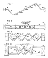
- Figures 7 and 8 show an embodiment of this invention wherein the straight parallel conduits 36, 37 and the associated sensors 56, 58 and driving mechanism are isolated from the effects of such temperature changes and thermal gradients.
- the straight conduits 36, 37 are connected to the support 32 through flexible, S-shaped conduits 90 and 92, respectively.
- the conduits 36, 37 are connected to the support 40 through flexible, S-shaped conduits 94 and 96, respectively. Rapid support plates 98, 100 firmly bonded to the straight conduits 36, 37 accurately define their effective lengths and hold them in precise parallel relationship when in the rest positions shown in Figure 4 by the dot-dash lines 36b and 37b.
- Figures 9 and 10 show an embodiment of this invention wherein the effects of temperature changes and thermal gradients are nullified or at least reduced by the provision of a pair of helically shaped conduits 102, 104 wound in clockwise and anticlockwise directions, respectively, about a common centre line 106 at a selected pitch.
- Conduits of such shape act as spiral wound springs absorbing, without distortion, the otherwise deleterious effects of temperature changes and thermal gradients.
- the driving mechanism 48 and sensor 56 and 58 are conveniently located between cross-over points of the conduits 102 and 104.
Abstract
Description
- This invention relates to measuring the mass flow rate of a fluid flow.
- Devices are known which utilise the effect of angular motion on a moving fluid to directly measure mass flow. See for example, US Patent Nos. US-A-2 865 201 (Roth), US-A-3 355 944 and US-A-3 485 098 (Sipin).
- US Patent No. US-A-4109 524 (Smith discloses an apparatus and method for measuring mass flow rate through a conduit by reciprocating a section of the conduit to produce longitudinal angular rotation of that section. Linkages are connected to the section both for reciprocating it and for measuring a force exerted on the section, which force is due to an apparent force produced by mass flow through the conduit section. A direct measurement can thus be taken of the mass flow rate in this manner. To understand how mass flow rate can be measured using the effects of this force, reference is now made to Figure 1 of the accompanying drawings which shows an arrangement of vectors on an X, Y, Z coordinate system.
- When a moving mass m with a velocity vector V is acted upon by a force that causes angular velocity w about some axis, a force Fc is observed, the force conforming to the relationship:

- If a flow tube of conduit for carying a fluid, shown at 10 in Figure 1, is rotated in the
F c- 7 plane, in the clockwise direction shown by anarrow 12, this causes an angular velocity Z as shown in Figure 1. If, however, rather than rotating theconduit 10 in the one direction shown by anarrow 12, the conduit is caused to oscillate back and forth about its pivot point, which is shown at 16, the magnitude and polarity of the angular velocity w will also oscillate and, therefore, the magnitude and polarity of the force F c will oscillate proportionately. - For any point along the
tube 10, for example apoint 14, a displacement vector can be represented fcor small amplitudes as lying along the y -axis only. As thetube 10 is forced to oscillate by a sinusoidal driver about itspivot point 16 with very small amplitude, and with thepoint 14 far from thepivot point 16, then the magnitude of its displacement, velocity and acceleration vector can be represented by a graph shown in Figure 2 of the accompanying drawings. The displacement of thepoint 14 along the Y-axis is shown by asolid line 20. The velocity v of thepoint 14 is shown by a dash double dot line 22: this is in the units of, for example, m/s and represents dy/dt, that is the first derivative of displacement with respect to time. - The acceleration A is shown by a
solid line 26 and represents the second derivative of displacement with respect to time, namely d2y/dt2, being in units of, for example, m/s2. - If there is a fluid flowing in the
tube 10, a force
tube 10 itself and is associated with an accelerationA ', with -F c andA ' being directed along theY -axis. The magnitude ofA ' is shown by adashed line 28. From the definition of the force -F c set forth above, it can be seen that this force is proportional to the velocity of thepoint 14, which is 90° out of phase with the acceleration due to the driving force applied to thetube 10. The resultant force acting at thepoint 14 will be the sum of the driving force and the force - F c, with these two forces being 90° out of phase. A dot-dash line orcurve 24 represents the sum associated with the accelerationsA plusA ', which is proportional to the sum of the driving force and the force -F c. A phase difference of (p between the original driving acceleration and the resultant summed acceleration will, therefore, be a direct measurement of the force -F c which id directly proportional to the mass flow rate. - If the driving force is sinusoidal, then its displacement, velocity and acceleration will likewise be sinusoidal and vary by 90° and 180° respectively. This allows the phase difference ϕ to be equal regardless of whether it is measured relative to the displacement, velocity or acceleration functions of the drive force verses resultant drive force plus the force -
F c. - The present invention is drawing to methods of and apparatus for measuring the mass flow rate of a fluid flow.
- According to one aspect of the invention there is provided apparatus for measuring the mass flow rate of a fluid flow, which apparatus comprises a pair of parallel conduits which have opposite ends, an axis and a mid-point, support means for supporting the opposite ends at substantially fixed locations, drive means for oscillating the conduits between their opposite ends and in a direction transverse to their axes, connector means on the support means for supplying fluid to the conduits and for dividing the flowing of fluid substantially equally between the conduits, and at least one conduit movement sensor provided at a location spaced from the mid-point and spaced from both opposite ends. The movement sensot may either sense displacement, velocity or acceleration. A phase difference between the sensed motion and the driving motion is a measurement of mass flow rate for the fluid through the conduits.
- The drive means may be provided at the mid-point of the conduits and a pair of sensors may be provided on opposite side of the mid-point. The upstream sensor lags the driving force with regard to phase and the downstream sensor leads the driving force. A measurement of phase lead and phase lag yields a measurement of mass flow rate.
- According to another aspect of the invention there is provided apparatus for measuring the mass flow rate of a fluid flow, the apparatus including a pair of parallel conduits mounted in side-by-side relationship with their ends being fixedly supported. Drive means is provided in the middle of the conduits and between them for applying lateral oscillations to the conduits which displace the conduits repeatedly away from and towards each other. This oscillation is permitted due to the flexibility of the conduits and since their ends are held at fixed locations. Sensors are provided on either side of the drive means and roughly half way between the drive means and each respective support. These sensors produce signals which correspond to the velocity of the tubes at the locations of the sensors. The supports comprise connectors and passages for supplying a mass flow which is divided approximately evenly between the two conduits through one of the supports and then recombined and discharged from the other support. The two spaced apart conduits, each meant for carrying about one half of the flow are, in use, forced to oscillate between fixed points in order to impart a reciprocating angular rotation to the conduits. With no fluid passing through the conduits, the frequency of oscillation for the drive means will exactly match and be in phase with the frequency of oscillations sensed by the two sensors. If a mass flow begins to pass through the conduits, however, all the sensors will continue to sense the same frequency as the driving frequency; the leading sensor in the direction of mass flow will lag the driving frequency with regard to its phase and the downstream sensor will lead the driving frequency, again with regard to phase. This phase lead and lag is directly usable as a measurement, which may be a continuous measurement, of mass flow rate through the conduits. According to a further aspect of the invention there is provided a method of measuring mass flow rate which utilises the difference in phase between sensed movements of oscillating parallel conduits and an oscillating force supplied near the mid-point of the conduits.
- According to yet another aspect of the invention there is provided apparatus for measuring the mass flow rate of a fluid flow, the apparatus comprising: a pair of straight parallel conduits each having opposite ends, an axis and a mid-point between the opposite ends;
- support means connected to the conduits for holding the opposite ends of the conduits at substantially fixed positions;
- connector means connected to the support means for supplying a fluid flow, whose mass flow rate is to be measured, to the pair of parallel conduits, the arrangement being such that each conduit receives about one half of the fluid flow at one end of the support means and the fluid flow is recombined at the other end of the support means;
- drive means associated with the conduits for oscillating the conduits towards and away from each other at a selected frequency in a direction transverse to their respective axes and substantially at their respective mid-points; and
- at least one sensor for sensing motion of the conduits at a sensing point spaced from each mid-point and from the opposite ends of the conduits for sensing any phase difference of the selected frequency between the conduits; the support means including flexible conduits for connecting fluid flow into and out of each of the straight parallel conduits to absorb thermal stress whereby deformation or rupture of the straight parallel conduits due to temperature changes or temperature gradients is inhibited.
- According to a still further aspect of the invention there is provided apparatus for measuring the mass flow rate of a fluid flow, the apparatus comprising: a pair of conduits arranged to receive approximately half the total fluid flow and wound about a common centre line to form a spiral coil of predetermined diameter and pitch and having a mid cross-over point and a cross-over point on either side of the mid cross-over point;
- drive means for oscillating the conduits, at the mid cross-over point, towards and away from each other at a selected frequency; and
- a sensor for sensing motion of the conduits at the cross-over point on either side of the mid cross-over point for sensing phase difference between the sensors.
- The invention may be so embodied as to provide apparatus for measuring mass flow rate which is of high accuracy and resolution and which is self-compensating for changes in temperature and thermal gradients.
- Apparatus in accordance with the invention for measuring mass flow rate may be so implemented as to be simple in design, rugged in construction and economical to manufacture.
- The invention will now be further described, by way of illustrative and non-limiting example, with reference to the accompanying drawings, in which:
- Figure 1 is a diagram showning a coordinate system in which a tube or conduit for carrying a mass flow of fluid can be rotated to illustrate the occurrence of a force Fe;
- Figure 2 is a graph showing various characteristics of motion and forces experienced at a certain point on the tube or conduit shown in Figure 1;
- Figure 3 is a side elevational view of an embodiment of the invention;
- Figure 4 is a schematic representation of the movement experienced by conduits of the apparatus embodying the invention;
- Figure 5 is a diagram showning the maximum amplitude of an oscillating conduit;
- Figure 6 is a graph of two sinusoidal curves which are of equal frequency but out of phase, showing a time difference t1 between them;
- Figures 7 and 8 are, respectively, a plan view and a side elevational view of a modified form of the apparatus embodying the invention; and
- Figures 9 and 10 are, respectively, a plan view and a side elevational view of a further modified form of the apparatus embodying the invention.
- Figure 3 shows an apparatus or device embodying the invention which is used for measuring the mass flow rate of a fluid supplied to an
inlet connection 30. Theinlet connection 30 is connected to a first support orsupport structure 32 which fixed in position ends 34 and 35 of a pair of stright parallel conduits ortubes 36 and 37. A Y-shapedpassage 38 is defined in thesupport 32 for dividing the mass flow into theconnection 30 into two at least approximately equal parts. Thus, half the mass flow is supplied to theconduit 36 and the other half to the conduit 37. - The
conduits 36 and 37 have opposite ends 42 and 43 respectively, which are connected to a second support orsupport structure 40 which carries anoutlet connection 44. A Y-shaped passage 46 is defined in thesupport 40 for combining the flows of theconduits 36 and 37 back together and into thedischarge connection 44. - A driving mechanism or
driver 48 is provided near the middle of and between theconduits 36 and 37. Thedriving mechanism 48 includes asolenoid coil 54 which is fixed, for example, to the conduit 36 (at a point "u"), and apermanent magnet 52 which rides in thecoil 54 and is fixed to the conduit 37 (at a point "v"). By applying electricity to thecoil 54 at a selected frequency, theconduits 36 and 37 can be made to oscillate towards and away from each other in an up and down direction. Figure 4, which is a schematic representation of the apparatus shown in Figure 3, shows theconduits 36 and 37 as lines. The maximum amplitude of the displacement that theconduits 36 and 37 achieve away from each other are shown bysolid lines lines conduits 36 and 37 are shown bu dot-dash lines - Referring again to Figure 3, the
conduits 36 and 37 are provided with a pair ofsensors driving mechanism 48. Thesensor 56 comprises apermanent magnet 62 which is magnetically coupled to acoil 66, the magnet and coil being connected to theconduits 37 and 36, respectively, (at points "b" and "a", respectively). In a similar fashion, thesensor 58 includes apermanent magnet 72 which rides in acoil 76, the magnet and coil being connected to theconduits 37 and 36, respectively (at points "d" and "c", respectively). - By oscillating the
conduits 36 and 37 in the manner shown in Figure 4, sinusoidal currents are induced in thecoils conduits 36 and 37 towards and away from each other at the locations of therespective sensors conduits 36 and 37, the oscillation applied by thedriving mechanism 48 to the mid-points of theconduits 36 and 37 will generate signals in thesensors driving mechanism 48. However, when fluid passes through theconduits 36 and 37, a phase difference appears between the signals of thesensors sensor 56 generates a velocity signal which lags behind the velocity of thedriving mechanism 48 and thesensor 58 generates a signal which leads the velocity of thedriving mechanism 48. - A
phase measuring device 80 is connected to thesensors driving mechanism 48 or at least a power supply thereof, for measuring the phase lead and phase lag of the respective velocity signals. The phase lead and phase lag, relative to the velocity of thedriving mechanism 48, is related directly to the mass flow rate of the fluid flowing through theconduits 36 and 37. - Figure 5 is a schematic illustration of one of the
conduits 36 and 37. The position of one of thesensors - In the following analysis, displacement from the point "o" is designated by the letter y.
- For any point on the flow tube, the displacement y of the tube from its rest position, while the tube is being forced to oscillate at resonance with a maximum amplitude A in simple harmonic motion, is given by:
- y = A sin wt
- where
- y = the displacement from the rest position;
- A = the maximum amplitude;
- w = 2 f;
- f = the resonant frequency; and
- t = time (t = 0 when the oscillation begins).
- Since the tube is fixed at both ends and can only move transversely to its own rest axis, the displacement y is up and down. The velocity v of the point "o" up and down is then:


V /R| (V =w xr ); and V c = the velocity of the fluid flowing past the point "o". If k = the spring constant of the tube at the point "o", then the induced oscillating force amplitude is given by:


- Equation (9) mathematically shows that the resultant force on the point "o" is at the same frequency as both the driving resonant oscillations, B1 cos wt and B2 sin wt, but is out of phase by an amount β, where: 0 = arctan (B1/B2) = arctan (-2wAmcVc/ -kAr) (10) or:


- Thus, the force acting on the point "o" is sinusoidal and at the same frequency as the driving force and only differs by a phase change β. The displacement, velocity or acceleration functions (as well as any higher derivatives of these) also differ in phase from the corresponding drive force by the same amount:

- For very small phase shifts, Equation (12) becomes

- In order to eliminate the frequency dependent term f, it is necessary to examine the two signals, which differ only in phase cp, as they are represented in terms of amplitude against time in Figure 6.
- The frequencies of the signals are equal and their period T is given by:

- The period can also be expressed as:


- For any set of conditions, k and r will be constants, and, therefore, a measurement of ti will be directly proportional to the mass flow rate. It is obvious that ti can be measured along any line through the signals as shown in Figure 6 and is not restricted to the "zero crossing" base line. The line difference t1 can be measured between any two points equal first and second derivatives during any one cycle of the two signals regardless of gain or DC offset factors. In the present design, the point "a" on the split parallel conduit arrangement of Figure 3 will follow the above progression. The mass flow rate can be directly measured by measuring the time difference ti between the induced signal at the point "u" and the mass flow rate effected signal at the point "a". With flow as shown in Figure 3, the point "a" will lag the point "u". Likewise, the point "b" will lag the point "v", the point "c" will lead the point "u" and the point "d" will lead the point "v". )The phase angle amplitude will be equal between all these respective points with leading points positive and lagging point negative). Therefore, the totel phase difference ϕ between the lag at the points "a" and "b" and the lead at the points "c" and "d" will provide a signal sampling the total direct mass flow rate through both the
conduits 36 and 37 twice, as a weighted average. The sum of the lead and lag phase angles will, therefore, cancel and provide the resonant frequency data necessary to maintain the tubes at their natural resonant frequency regardless of pressure, density or temperature variations. - The split parallel conduit arrangement of Figure 3 also allows both halves of the
drive coil 48 and both of the sensor coils 66, 76 to be mounted to theflow conduits 36, 37 directly and help reduce common mode vibration noise and improve performance (provided that the sprung masses at the points "a", "b", "c" and "d" are all equal, and at the points "u" and "v" are equal). - Thus, advantages of the split parallel conduit approach of Figure 3 are as follows. Direct mass flow rate measurement proportional to the time measurement between points with equal first and second derivatives during any one cycle of two equal frequency signals; simple, rugged mechanical design; easy of assembly; small overall size; ease of installation; process fluid density insensitive; only slight temperature dependency; ease of scaling up and down in size; process fluid viscosity insensitive; and applicable to liquids, gases and slurries.
- In the alternative, phase measuring devices, such as that shown in Figure 3 at 80, are known. An example is the Hewlett Packard Model 3575A. The phase difference from the driving point to the sensing point near the centre of the tubes, and the sensing point, spaced away from the centre, can thus be utilised as a measurement of mass flow rate. Sensors, as provided on both sides of the driving mechanism, increase accuracy.
- While the embodiment of this invention shown in Figure 3 will, under ordinary conditions, give an accurate measurement of mass flow, a change in temperature or thermal gradient between the straight
parallel conduits 36, 37 and theirsupports - Figures 7 and 8 show an embodiment of this invention wherein the straight
parallel conduits 36, 37 and the associatedsensors straight conduits 36, 37 are connected to thesupport 32 through flexible, S-shapedconduits conduits 36, 37 are connected to thesupport 40 through flexible, S-shapedconduits Rapid support plates straight conduits 36, 37 accurately define their effective lengths and hold them in precise parallel relationship when in the rest positions shown in Figure 4 by the dot-dash lines - Figures 9 and 10 show an embodiment of this invention wherein the effects of temperature changes and thermal gradients are nullified or at least reduced by the provision of a pair of helically shaped
conduits common centre line 106 at a selected pitch. Conduits of such shape act as spiral wound springs absorbing, without distortion, the otherwise deleterious effects of temperature changes and thermal gradients. Thedriving mechanism 48 andsensor conduits
Claims (6)
Applications Claiming Priority (2)
| Application Number | Priority Date | Filing Date | Title |
|---|---|---|---|
| US06/917,631 US4763530A (en) | 1986-10-10 | 1986-10-10 | Apparatus and method for continuously measuring mass flow |
| US917631 | 1986-10-10 |
Related Child Applications (1)
| Application Number | Title | Priority Date | Filing Date |
|---|---|---|---|
| EP90200728.5 Division-Into | 1987-10-09 |
Publications (2)
| Publication Number | Publication Date |
|---|---|
| EP0263719A1 true EP0263719A1 (en) | 1988-04-13 |
| EP0263719B1 EP0263719B1 (en) | 1991-12-04 |
Family
ID=25439084
Family Applications (2)
| Application Number | Title | Priority Date | Filing Date |
|---|---|---|---|
| EP90200728A Expired - Lifetime EP0381302B1 (en) | 1986-10-10 | 1987-10-09 | Measuring mass flow rates of fluid flows |
| EP87308967A Expired - Lifetime EP0263719B1 (en) | 1986-10-10 | 1987-10-09 | Measuring mass flow rates of fluid flows |
Family Applications Before (1)
| Application Number | Title | Priority Date | Filing Date |
|---|---|---|---|
| EP90200728A Expired - Lifetime EP0381302B1 (en) | 1986-10-10 | 1987-10-09 | Measuring mass flow rates of fluid flows |
Country Status (14)
| Country | Link |
|---|---|
| US (1) | US4763530A (en) |
| EP (2) | EP0381302B1 (en) |
| JP (1) | JP2517316B2 (en) |
| KR (1) | KR960000098B1 (en) |
| CN (1) | CN1021128C (en) |
| AU (1) | AU596447B2 (en) |
| BR (1) | BR8704923A (en) |
| CA (1) | CA1300402C (en) |
| DE (2) | DE3788880T2 (en) |
| ES (2) | ES2028099T3 (en) |
| HK (2) | HK35992A (en) |
| IN (1) | IN167724B (en) |
| MX (1) | MX167151B (en) |
| SG (1) | SG18292G (en) |
Cited By (6)
| Publication number | Priority date | Publication date | Assignee | Title |
|---|---|---|---|---|
| WO1989004463A1 (en) * | 1987-11-09 | 1989-05-18 | Flowtec Ag | Process and device for detecting errors in measurements of mass flow of materials |
| FR2635865A1 (en) * | 1988-08-26 | 1990-03-02 | Danfoss As | FLOW RATE WORKING ACCORDING TO THE CORIOLIS III PRINCIPLE |
| EP0398103A1 (en) * | 1989-05-19 | 1990-11-22 | KROHNE MESSTECHNIK MASSAMETRON GmbH & Co. KG | Mass-flow measuring device |
| EP0579493A2 (en) * | 1992-07-15 | 1994-01-19 | Abb K-Flow Inc. | Fluid mass flow meters |
| EP0685712A1 (en) * | 1994-05-26 | 1995-12-06 | Endress + Hauser Flowtec AG | Mass flow sensor according to the Coriolis principle |
| US5796011A (en) * | 1993-07-20 | 1998-08-18 | Endress + Hauser Flowtech Ag | Coriolis-type mass flow sensor |
Families Citing this family (10)
| Publication number | Priority date | Publication date | Assignee | Title |
|---|---|---|---|---|
| US5343764A (en) * | 1986-10-28 | 1994-09-06 | The Foxboro Company | Coriolis-type mass flowmeter |
| KR960000099B1 (en) * | 1986-10-28 | 1996-01-03 | 더폭스보로 컴패니 | Coriolis-type mass flowmeter |
| US4957005A (en) * | 1989-10-05 | 1990-09-18 | Fischer & Porter Company | Coriolis-type flowmeter |
| DE59201625D1 (en) * | 1992-11-18 | 1995-04-13 | Flowtec Ag | Mass flow meter based on the Coriolis principle. |
| FR2707395B1 (en) * | 1993-07-09 | 1995-10-06 | Facom | Torque measurement tool, such as an electronic torque wrench. |
| US5546814A (en) * | 1994-10-26 | 1996-08-20 | The Foxboro Company | Parallel-flow coriolis-type mass flowmeter with flow-dividing manifold |
| WO2008064459A1 (en) * | 2006-11-30 | 2008-06-05 | Hatch Ltd. | Method and apparatus for fluid leak detection |
| DE102011089808A1 (en) | 2011-12-23 | 2013-06-27 | Endress + Hauser Flowtec Ag | Method or measuring system for determining a density of a fluid |
| CN103604475B (en) * | 2013-11-20 | 2016-08-24 | 东京计装(上海)仪表有限公司 | X-type deciliter stream device and effusion meter thereof |
| CN105760647B (en) * | 2014-12-19 | 2020-03-31 | 中国航空工业集团公司沈阳发动机设计研究所 | Quality weighted average calculation method |
Citations (6)
| Publication number | Priority date | Publication date | Assignee | Title |
|---|---|---|---|---|
| US3927565A (en) * | 1973-01-30 | 1975-12-23 | Bertin & Cie | Apparatus and method for measuring the mass flow of a fluid stream |
| US4559833A (en) * | 1982-09-30 | 1985-12-24 | Smith Meter Inc. | Meter for measuring mass flow rate |
| WO1986000699A1 (en) * | 1984-07-11 | 1986-01-30 | Exac Corporation | Improved apparatus for mass flow rate and density measurement |
| GB2167858A (en) * | 1984-11-27 | 1986-06-04 | Danfoss As | Mass flow meter working on the coriolis principle |
| GB2171200A (en) * | 1985-02-15 | 1986-08-20 | Danfoss As | Mass flow meters making use of coriolis effects |
| EP0196150A1 (en) * | 1985-03-25 | 1986-10-01 | International Control Automation Finance S.A. | Fluid flow measurement |
Family Cites Families (2)
| Publication number | Priority date | Publication date | Assignee | Title |
|---|---|---|---|---|
| US3329019A (en) * | 1964-10-26 | 1967-07-04 | Anatole J Sipin | Mass flow metering means |
| US4655089A (en) * | 1985-06-07 | 1987-04-07 | Smith Meter Inc. | Mass flow meter and signal processing system |
-
1986
- 1986-10-10 US US06/917,631 patent/US4763530A/en not_active Expired - Lifetime
-
1987
- 1987-07-28 IN IN579/CAL/87A patent/IN167724B/en unknown
- 1987-08-17 MX MX007765A patent/MX167151B/en unknown
- 1987-08-19 CA CA000544918A patent/CA1300402C/en not_active Expired - Fee Related
- 1987-09-02 KR KR1019870009699A patent/KR960000098B1/en not_active IP Right Cessation
- 1987-09-23 AU AU78892/87A patent/AU596447B2/en not_active Ceased
- 1987-09-24 BR BR8704923A patent/BR8704923A/en unknown
- 1987-10-01 JP JP62245946A patent/JP2517316B2/en not_active Expired - Lifetime
- 1987-10-09 CN CN87106872A patent/CN1021128C/en not_active Expired - Fee Related
- 1987-10-09 ES ES198787308967T patent/ES2028099T3/en not_active Expired - Lifetime
- 1987-10-09 ES ES90200728T patent/ES2048409T3/en not_active Expired - Lifetime
- 1987-10-09 EP EP90200728A patent/EP0381302B1/en not_active Expired - Lifetime
- 1987-10-09 DE DE90200728T patent/DE3788880T2/en not_active Expired - Fee Related
- 1987-10-09 EP EP87308967A patent/EP0263719B1/en not_active Expired - Lifetime
- 1987-10-09 DE DE8787308967T patent/DE3774993D1/en not_active Expired - Fee Related
-
1992
- 1992-02-27 SG SG182/92A patent/SG18292G/en unknown
- 1992-05-21 HK HK359/92A patent/HK35992A/en not_active IP Right Cessation
-
1994
- 1994-08-04 HK HK77494A patent/HK77494A/en not_active IP Right Cessation
Patent Citations (6)
| Publication number | Priority date | Publication date | Assignee | Title |
|---|---|---|---|---|
| US3927565A (en) * | 1973-01-30 | 1975-12-23 | Bertin & Cie | Apparatus and method for measuring the mass flow of a fluid stream |
| US4559833A (en) * | 1982-09-30 | 1985-12-24 | Smith Meter Inc. | Meter for measuring mass flow rate |
| WO1986000699A1 (en) * | 1984-07-11 | 1986-01-30 | Exac Corporation | Improved apparatus for mass flow rate and density measurement |
| GB2167858A (en) * | 1984-11-27 | 1986-06-04 | Danfoss As | Mass flow meter working on the coriolis principle |
| GB2171200A (en) * | 1985-02-15 | 1986-08-20 | Danfoss As | Mass flow meters making use of coriolis effects |
| EP0196150A1 (en) * | 1985-03-25 | 1986-10-01 | International Control Automation Finance S.A. | Fluid flow measurement |
Cited By (9)
| Publication number | Priority date | Publication date | Assignee | Title |
|---|---|---|---|---|
| WO1989004463A1 (en) * | 1987-11-09 | 1989-05-18 | Flowtec Ag | Process and device for detecting errors in measurements of mass flow of materials |
| FR2635865A1 (en) * | 1988-08-26 | 1990-03-02 | Danfoss As | FLOW RATE WORKING ACCORDING TO THE CORIOLIS III PRINCIPLE |
| EP0398103A1 (en) * | 1989-05-19 | 1990-11-22 | KROHNE MESSTECHNIK MASSAMETRON GmbH & Co. KG | Mass-flow measuring device |
| EP0579493A2 (en) * | 1992-07-15 | 1994-01-19 | Abb K-Flow Inc. | Fluid mass flow meters |
| EP0579493A3 (en) * | 1992-07-15 | 1995-09-06 | Abb K Flow Inc | Fluid mass flow meters |
| US5458005A (en) * | 1992-07-15 | 1995-10-17 | Abbk-Flow Inc. | Fluid mass flow meters |
| US5796011A (en) * | 1993-07-20 | 1998-08-18 | Endress + Hauser Flowtech Ag | Coriolis-type mass flow sensor |
| EP0685712A1 (en) * | 1994-05-26 | 1995-12-06 | Endress + Hauser Flowtec AG | Mass flow sensor according to the Coriolis principle |
| US5602345A (en) * | 1994-05-26 | 1997-02-11 | Endress + Hauser Flowtec Ag | Double straight tube coriolis type mass flow sensor |
Also Published As
| Publication number | Publication date |
|---|---|
| EP0263719B1 (en) | 1991-12-04 |
| ES2048409T3 (en) | 1994-03-16 |
| DE3788880D1 (en) | 1994-03-03 |
| MX167151B (en) | 1993-03-08 |
| BR8704923A (en) | 1988-05-24 |
| SG18292G (en) | 1992-04-16 |
| HK77494A (en) | 1994-08-12 |
| DE3788880T2 (en) | 1994-05-05 |
| HK35992A (en) | 1992-05-29 |
| KR960000098B1 (en) | 1996-01-03 |
| AU596447B2 (en) | 1990-05-03 |
| JPS6398521A (en) | 1988-04-30 |
| CA1300402C (en) | 1992-05-12 |
| EP0381302B1 (en) | 1994-01-19 |
| DE3774993D1 (en) | 1992-01-16 |
| KR880005444A (en) | 1988-06-29 |
| US4763530A (en) | 1988-08-16 |
| ES2028099T3 (en) | 1992-07-01 |
| CN1021128C (en) | 1993-06-09 |
| EP0381302A1 (en) | 1990-08-08 |
| AU7889287A (en) | 1988-04-14 |
| JP2517316B2 (en) | 1996-07-24 |
| IN167724B (en) | 1990-12-15 |
| CN87106872A (en) | 1988-06-15 |
Similar Documents
| Publication | Publication Date | Title |
|---|---|---|
| US4622858A (en) | Apparatus and method for continuously measuring mass flow | |
| EP0263719A1 (en) | Measuring mass flow rates of fluid flows | |
| US4733569A (en) | Mass flow meter | |
| US4658657A (en) | Mass flow meter | |
| KR960000099B1 (en) | Coriolis-type mass flowmeter | |
| US4711132A (en) | Apparatus for mass flow rate and density measurement | |
| US6691583B2 (en) | Vibratory transducer | |
| RU2344377C2 (en) | Vibration type measuring transducer for measuring flowing fluid media and measuring device | |
| EP0188572B1 (en) | Improved apparatus for mass flow rate and density measurement | |
| US5054326A (en) | Density compensator for coriolis-type mass flowmeters | |
| US4811606A (en) | Mass flowmeter | |
| CA2443375C (en) | Vibratory transducer | |
| US4703660A (en) | Apparatus and method for continuously measuring mass flow | |
| JP2575203B2 (en) | Mass flow meter with improved accuracy by compensating for asymmetry and viscous damping | |
| US4729243A (en) | Mass-flow measuring instrument | |
| JPH08505698A (en) | Inflow type Coriolis mass flowmeter | |
| JPH09512341A (en) | Coriolis mass flow meter | |
| EP0185709A1 (en) | Apparatus for mass flow rate and density measurement | |
| US4984472A (en) | Apparatus for mass flow rate and density measurement | |
| US5700958A (en) | Inertia force flowmeter with transverse pressure gradient sensors | |
| WO1995004259A1 (en) | Method and apparatus for measuring mass flow | |
| US6178828B1 (en) | Free standing Coriolis driver | |
| CA1257784A (en) | Apparatus for mass flow rate and density measurement | |
| CA1257783A (en) | Apparatus for mass flow rate and density measurement | |
| JPS61290324A (en) | Mass flowmeter |
Legal Events
| Date | Code | Title | Description |
|---|---|---|---|
| PUAI | Public reference made under article 153(3) epc to a published international application that has entered the european phase |
Free format text: ORIGINAL CODE: 0009012 |
|
| AK | Designated contracting states |
Kind code of ref document: A1 Designated state(s): DE ES FR GB IT SE |
|
| 17P | Request for examination filed |
Effective date: 19880927 |
|
| 17Q | First examination report despatched |
Effective date: 19891130 |
|
| RAP1 | Party data changed (applicant data changed or rights of an application transferred) |
Owner name: INTERNATIONAL CONTROL AUTOMATION FINANCE S.A. |
|
| GRAA | (expected) grant |
Free format text: ORIGINAL CODE: 0009210 |
|
| AK | Designated contracting states |
Kind code of ref document: B1 Designated state(s): DE ES FR GB IT SE |
|
| XX | Miscellaneous (additional remarks) |
Free format text: TEILANMELDUNG 90200728.5 EINGEREICHT AM 27/03/90. |
|
| REF | Corresponds to: |
Ref document number: 3774993 Country of ref document: DE Date of ref document: 19920116 |
|
| ET | Fr: translation filed | ||
| ITF | It: translation for a ep patent filed |
Owner name: ST. ASSOC. MARIETTI & PIPPARELLI |
|
| REG | Reference to a national code |
Ref country code: ES Ref legal event code: FG2A Ref document number: 2028099 Country of ref document: ES Kind code of ref document: T3 |
|
| PLBI | Opposition filed |
Free format text: ORIGINAL CODE: 0009260 |
|
| 26 | Opposition filed |
Opponent name: ENDRESS + HAUSER FLOWTEC AG Effective date: 19920819 |
|
| PLBN | Opposition rejected |
Free format text: ORIGINAL CODE: 0009273 |
|
| STAA | Information on the status of an ep patent application or granted ep patent |
Free format text: STATUS: OPPOSITION REJECTED |
|
| 27O | Opposition rejected |
Effective date: 19931022 |
|
| EAL | Se: european patent in force in sweden |
Ref document number: 87308967.6 |
|
| PGFP | Annual fee paid to national office [announced via postgrant information from national office to epo] |
Ref country code: GB Payment date: 19990913 Year of fee payment: 13 |
|
| PGFP | Annual fee paid to national office [announced via postgrant information from national office to epo] |
Ref country code: SE Payment date: 19990920 Year of fee payment: 13 Ref country code: FR Payment date: 19990920 Year of fee payment: 13 |
|
| PGFP | Annual fee paid to national office [announced via postgrant information from national office to epo] |
Ref country code: DE Payment date: 19990927 Year of fee payment: 13 |
|
| PGFP | Annual fee paid to national office [announced via postgrant information from national office to epo] |
Ref country code: ES Payment date: 19991020 Year of fee payment: 13 |
|
| PG25 | Lapsed in a contracting state [announced via postgrant information from national office to epo] |
Ref country code: GB Free format text: LAPSE BECAUSE OF NON-PAYMENT OF DUE FEES Effective date: 20001009 |
|
| PG25 | Lapsed in a contracting state [announced via postgrant information from national office to epo] |
Ref country code: ES Free format text: LAPSE BECAUSE OF NON-PAYMENT OF DUE FEES Effective date: 20001010 |
|
| PG25 | Lapsed in a contracting state [announced via postgrant information from national office to epo] |
Ref country code: SE Free format text: THE PATENT HAS BEEN ANNULLED BY A DECISION OF A NATIONAL AUTHORITY Effective date: 20001030 |
|
| GBPC | Gb: european patent ceased through non-payment of renewal fee |
Effective date: 20001009 |
|
| EUG | Se: european patent has lapsed |
Ref document number: 87308967.6 |
|
| PG25 | Lapsed in a contracting state [announced via postgrant information from national office to epo] |
Ref country code: FR Free format text: LAPSE BECAUSE OF NON-PAYMENT OF DUE FEES Effective date: 20010629 |
|
| PG25 | Lapsed in a contracting state [announced via postgrant information from national office to epo] |
Ref country code: DE Free format text: LAPSE BECAUSE OF NON-PAYMENT OF DUE FEES Effective date: 20010703 |
|
| REG | Reference to a national code |
Ref country code: FR Ref legal event code: ST |
|
| REG | Reference to a national code |
Ref country code: ES Ref legal event code: FD2A Effective date: 20011113 |
|
| PG25 | Lapsed in a contracting state [announced via postgrant information from national office to epo] |
Ref country code: IT Free format text: LAPSE BECAUSE OF NON-PAYMENT OF DUE FEES;WARNING: LAPSES OF ITALIAN PATENTS WITH EFFECTIVE DATE BEFORE 2007 MAY HAVE OCCURRED AT ANY TIME BEFORE 2007. THE CORRECT EFFECTIVE DATE MAY BE DIFFERENT FROM THE ONE RECORDED. Effective date: 20051009 |