US4729243A - Mass-flow measuring instrument - Google Patents
Mass-flow measuring instrument Download PDFInfo
- Publication number
- US4729243A US4729243A US06/859,360 US85936086A US4729243A US 4729243 A US4729243 A US 4729243A US 85936086 A US85936086 A US 85936086A US 4729243 A US4729243 A US 4729243A
- Authority
- US
- United States
- Prior art keywords
- conduit
- conduits
- pair
- tuning fork
- driver
- Prior art date
- Legal status (The legal status is an assumption and is not a legal conclusion. Google has not performed a legal analysis and makes no representation as to the accuracy of the status listed.)
- Expired - Lifetime
Links
Images


Classifications
-
- G—PHYSICS
- G01—MEASURING; TESTING
- G01F—MEASURING VOLUME, VOLUME FLOW, MASS FLOW OR LIQUID LEVEL; METERING BY VOLUME
- G01F1/00—Measuring the volume flow or mass flow of fluid or fluent solid material wherein the fluid passes through a meter in a continuous flow
- G01F1/76—Devices for measuring mass flow of a fluid or a fluent solid material
- G01F1/78—Direct mass flowmeters
- G01F1/80—Direct mass flowmeters operating by measuring pressure, force, momentum, or frequency of a fluid flow to which a rotational movement has been imparted
- G01F1/84—Coriolis or gyroscopic mass flowmeters
- G01F1/8409—Coriolis or gyroscopic mass flowmeters constructional details
- G01F1/8413—Coriolis or gyroscopic mass flowmeters constructional details means for influencing the flowmeter's motional or vibrational behaviour, e.g., conduit support or fixing means, or conduit attachments
-
- G—PHYSICS
- G01—MEASURING; TESTING
- G01F—MEASURING VOLUME, VOLUME FLOW, MASS FLOW OR LIQUID LEVEL; METERING BY VOLUME
- G01F1/00—Measuring the volume flow or mass flow of fluid or fluent solid material wherein the fluid passes through a meter in a continuous flow
- G01F1/76—Devices for measuring mass flow of a fluid or a fluent solid material
- G01F1/78—Direct mass flowmeters
- G01F1/80—Direct mass flowmeters operating by measuring pressure, force, momentum, or frequency of a fluid flow to which a rotational movement has been imparted
- G01F1/84—Coriolis or gyroscopic mass flowmeters
- G01F1/845—Coriolis or gyroscopic mass flowmeters arrangements of measuring means, e.g., of measuring conduits
- G01F1/8468—Coriolis or gyroscopic mass flowmeters arrangements of measuring means, e.g., of measuring conduits vibrating measuring conduits
- G01F1/8472—Coriolis or gyroscopic mass flowmeters arrangements of measuring means, e.g., of measuring conduits vibrating measuring conduits having curved measuring conduits, i.e. whereby the measuring conduits' curved center line lies within a plane
- G01F1/8477—Coriolis or gyroscopic mass flowmeters arrangements of measuring means, e.g., of measuring conduits vibrating measuring conduits having curved measuring conduits, i.e. whereby the measuring conduits' curved center line lies within a plane with multiple measuring conduits
Definitions
- This invention relates generally to a device to measure the true mass flow rate of a fluid.
- the device measures the mass flow rate of a fluid from the Coriolis force resulting from the flow of fluid through the device during oscillation thereof.
- U.S. Pat. No. 3,132,512 (“Roth”) describes a gyroscopic mass flowmeter that operates on the principle of Coriolis forces and, in theory, is capable of measuring true mass flow rate.
- the mass flowmeter is basically a circular tube that is excited to vibrate in a direction normal to the plane in which it is at rest.
- the fluid whose mass flow rate is to be measured is made to flow through the tube.
- the Coriolis force on the tube resulting from the combined fluid flow and vibration causes the tube to twist.
- the angle of twist of the tube is proportional to the true mass flow rate.
- the angle of twist can be determined by measuring the time difference between the instant that one side of the tube crosses a given reference plane and the instant that the opposite side crosses the same reference plane.
- the measurement produced by this instrument is insensitive to variations in the environment (in particular, motion) in which the device operates.
- the invention overcomes the errors due to the motion of the base of the instrument by utilizing a plurality of tubes, preferably four, arranged and operated so that the phase of the oscillation of the tubes and direction of the flow of the fluid cancel the errors due to the base motion.
- FIG. 1 is an isometric view of a prior art mass-flow sensor having a single U-shaped tube attached to a base;
- FIG. 2 is an isometric view of the U-shaped tube of FIG. 1 having a coordinate system and dimensions of the tube described;
- FIG. 3 is an enlarged end view of the mass-flow sensor of FIG. 1 taken along arrows 3--3 in FIG. 1;
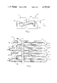
- FIG. 4 is an isometric view of a first embodiment of a mass-flow measuring instrument of the present invention having four (4) U-shaped tubes arranged on an associated base;
- FIG. 5 is a isometric view of a second embodiment of a mass-flow measuring instrument of the present invention having four (4) U-shaped tubes arranged on an associated base;
- FIG. 6a is a top view of a housing in which the mass-flow measuring instrument of FIG. 4 is mounted;
- FIG. 6b is an end view of the housing of FIG. 6a taken along arrows 6b--6b;
- FIG. 7a is a schematic diagram of a plurality of timers associated with the housing of FIGS. 6a and 6b;
- FIG. 7b is a schematic diagram of a computational circuit associated with the plurality of timers of FIG. 7a.
- FIG. 8 is a schematic diagram of a driving mechanism which provides vibration to each pair of U-shaped tubes of the mass-flow measuring instrument of the present invention.
- FIG. 1 illustrates a prior art mass-flow sensor 10 comprising a base 11 and a single U-shaped tube 12 attached thereto.
- Fluid 15 flows into one free end of the U-shaped tube 12 which is a fluid inlet 12a, through a first side 12b, around the tube bend 12c, through a second side 12d and out through the other free end which is a fluid outlet 12e.
- a vibration V applied to the U-shaped tube 12 during operation is perpendicular to the plane of the U-shaped tube 12 at rest.
- a coordinate system i.e., x, y, z axes
- dimensions of the U-shaped tube 12 of FIG. 1 are shown in FIG. 2.
- the following parameters of the tube 12 shown in FIG. 2 are defined as follows:
- w x , w y , w z total angular velocity components of the U-shaped tube 12 about the x, y, and z axes, respectively;
- w xe , w ye , w ze externally applied angular velocity components of the instrument base 11 about the x, y, and z axes, respectively;
- w yi internally applied angular velocity (about the y axis) due to the vibration V applied to the U-shaped tube 12 during operation;
- I x , I y , I z (not shown): moments of inertia of the U-shaped tube 12 about the x, y, and z axes, respectively;
- T x total resultant torque acting upon the U-shaped tube 12 about the x axis
- m mass of the moving fluid 15 contained in length L of one side of the U-shaped tube 12;
- r y one-half the width of the U-shaped tube 12 measured from the center lines of the inlet 12a and outlet 12e;
- L d distance from the base 11 to the reference point at which deflections of the U-shaped tube 12 are measured.
- the total angular velocity components of the U-shaped tube 12 form the following relationships with the other parameters:
- FIG. 3 shows an end view of the mass-flow sensor 10 during operation when the vibration V is applied thereto.
- the applied vibration V is normal to the plane 16 of the U-shaped tube 12 at rest (as also shown in FIG. 1).
- Such a vibration V causes the U-shaped tube 12 to twist with the bend section 12c at some twist angle ⁇ from its plane at rest.
- T x k ⁇ , where k is a constant
- the reference plane 16 is defined by the plane formed by the non-twisted U-shaped tube 12 when at rest (i.e., non-vibrating). The time difference between the two crossings is given by the equation:
- V t is the linear velocity at the reference point on each free end due to the applied vibration V.
- a positive ⁇ t corresponds to the first side 12b crossing the reference plane 16 before the second side 12d, while a negative ⁇ t corresponds to the second side 12d crossing first.
- the mass flow rate Q of the fluid 15 is given by the following equation:
- A is the cross-sectional area of the tube 12
- L is the length of one side of the tube 12
- ⁇ is the density of the fluid 15 in the tube 12.
- the moment of inertia of the U-shaped tube 12 about the x-axis is approximated by the equation:
- L d is the distance from the base 11 to the reference point at which the deflections are measured (see FIG. 2).
- Equation (3) On substitution of equations (2), (4), (5) and (6) into equation (3), the following equation is obtained: ##EQU1##
- This expression relates the time difference to the mass flow rate Q, the internally applied angular velocity w yi and external angular velocity components w x , w ye , w z for the reference directions shown in FIG. 2.
- a negative sign in the ⁇ t term indicates that the corresponding twist in the U-shaped tube 12, as shown in FIG. 3, is such that the second side 12d crosses the reference plane 16 before the first side 12b. If the fluid 15 flow direction of angular velocity directions are reversed, however, the signs of the corresponding terms must be changed.
- FIG. 4 shows an isometric view of a mass-flow measuring instrument 40 of the present invention.
- the instrument 40 comprises a rigid base 41 and four (4) U-shaped tubes 42, 43, 44, 45 attached to the base 41 as shown.
- the fluid 15 flows into an inlet 46 which is split at a coupling 46b so that half of the fluid 15 goes into the first U-shaped tube 42 and half of the fluid 15 goes into the second U-shaped tube 43.
- the outflow of fluid 15 from the first U-shaped tube 42 is piped to an inlet 47a of the third U-shaped tube 44, with the connection being made between those two tubes so that the fluid 15 flow direction in the first U-shaped tube 42 and in the third U-shaped tube 44 are in opposite directions.
- the outflow from the second U-shaped tube 43 is piped to an inlet 47b of the fourth U-shaped tube 45 so that the flow in that tube is opposite in direction to the flow in the second U-shaped tube 43.
- the outflows of the third and fourth U-shaped tubes 44, 45 are combined in a coupling 48b so that the total fluid 15 flow from the inlet 46 goes to the outlet 48 of the instrument 40.
- the instrument 40 is constructed so that the magnitude of the fluid 15 flow in each of the four tubes is equal.
- the base 41 of the instrument 40 is stiff and massive to prevent any significant distortion thereof due to the motion of the U-shaped tubes.
- the "plumbing" between the inlet 46 and the first two U-shaped tubes 42, 43; between the outlets of these tubes and the inlets 47a, 47b to the third and fourth U-shaped tubes 44, 45; and between the outlets of the third and fourth U-shaped tubes 44, 45 and the outlet 48 of the instrument 40 are negligibly short and very stiff relative to the size and flexibility of the U-shaped tubes, so that the entire structure consisting of the base 41; the two couplings 46b, 48b; the two inlets 47a, 47b to the third and fourth U-shaped tubes 44, 45; the inlet 46 and the outlet 48 can be regarded as a single rigid body.
- a number of alternate means for interconnecting the four U-shaped tubes can be used as long as the required fluid 15 flow direction in each U-shaped tube is maintained and the magnitude of the fluid 15 flow in each U-shaped tube is equal.
- One method to guarantee equal fluid 15 flow in each U-shaped tube is to interconnect the four U-shaped tubes in sequence (i.e., the inlet 46 to the first tube 42, the first tube 42 to the second tube 43, the second tube 43 to the third tube 44, the third tube 44 to the fourth tube 45 and the fourth tube 45 to the outlet 48) while maintaining the required fluid 15 flow directions in each U-shaped tube.
- the fluid 15 flows in the first U-shaped tube 42 and the second U-shaped tube 43 are in the same direction, but the respective vibrations V1, V2 are out of phase.
- the applied angular velocity for these two tubes have opposite signs.
- the flows of the fluid 15 in the third tube 44 and the fourth tube 45 are in opposite directions to those of the first and second tubes 42, 43, but, the vibration V3 of the third tube 44 is in phase with the vibration V1 of the first tube 42 and the vibration V4 of the fourth tube 45 is in phase with the vibration V2 of the second tube 43.
- the applied velocities of the first and third tubes 42, 44 are equal and both are opposite to the equal applied velocities of the second and fourth tubes 43, 45.
- FIG. 5 An alternate construction of the instrument 40 is shown in FIG. 5 in which the third and fourth U-shaped tubes 44, 45 are on the opposite side of the base 41.
- This alternate construction eliminates the need for the "plumbing" between the first and third U-shaped tubes 42, 44 and between the second and fourth U-shaped tubes 43, 45, and permits the inlet 46 and outlet 48 directions to be parallel. But it requires a housing that is nearly twice as long as that which is needed to contain the structure shown in FIG. 4.
- each set of sensors measures the time difference between the instant that one side of the corresponding U-shaped tube crosses the reference plane of the tube at rest and the instant that the other side crosses the same plane.
- ⁇ t if the first side 12b of a respective U-shaped tube crosses first, ⁇ t is positive; if the second side 12d crosses first, ⁇ t is negative.
- ⁇ t 1 , ⁇ t 2 , ⁇ t 3 and ⁇ t 4 denote the time difference as measured by the corresponding sets of sensors at the same instant of time for the first, second, third and fourth U-shaped tubes 42, 43, 44, 45, respectively. (Note that there are two measurements of ⁇ t for each U-shaped tube for each cycle of vibration.) Then, ##EQU2##
- Equation (12) subtracted from equation (13) yields one equation containing all the time differences: ##EQU5## It thus follows that the true mass flow rate Q can be computed using the following formula:
- FIGS. 6a and 6b illustrate one structure to measure the time differences from sensor pairs.
- the instrument 40 is mounted in a housing 60, as shown in FIGS. 6a and 6b, within which are mounted eight (8) sensors 61 . . . 68 and two (2) driver/pickoff assemblies 69a, 69b. Two sensors are used with each U-shaped tube (one sensor per side) and one driver/pickoff assembly is used with each pair of U-shaped tubes. Each of the sensors is mounted on the housing 60 and detects the instant of time at which a reference point on the corresponding side of the associated U-shaped tube crosses the reference plane, defined as the plane in which the respective U-shaped tube lies when it is not in motion.
- the signals from the sensors 62, 64, 66, 68 along side 1 indicate the instants that side 1 of the U-shaped tubes cross through the respective reference planes
- the signals from the sensors 61, 63, 65, 67 along side 2 indicate the instants that side 2 of the U-shaped tubes cross through the same respective reference planes.
- a timer 70, 71, 72, 73 is associated with each pair of sensors associated with each U-shaped tube.
- the sensor signal that occurs first starts the corresponding timer and the other sensor signal stops the same timer.
- the output of each timer is therefore the time difference between the instant that one side or leg of a respective U-shaped tube crosses the reference plane and the instant that the other side or leg of the same U-shaped tube crosses the same reference plane.
- Additional circuitry within each timer detects which sensor signal occurred first. If the sensor signal associated with side 1 of the respective tube occurs first, the time difference measurement is assigned a positive value; if the sensor signal associated with side 2 of the respective tube occurs first, the time difference measurement is assigned a negative value.
- the outputs of the timers 70, 71, 72, 73 are the time-difference ⁇ t 1 , ⁇ t 2 , ⁇ t 3 , and ⁇ t 4 , respectively that appear in Equation (16) from which the total mass flow rate Q t can be computed.
- FIG. 7b shows a computational circuit 74 that algebraically combines the time differences ⁇ t 1 , ⁇ t 2 , ⁇ t 3 and ⁇ t 4 , in accordance with Equation (16) to produce an output 75 corresponding to the total mass flow rate Q t .
- a variety of sensing means can be employed to obtain a signal at the instant that a reference point on the U-shaped tube crosses the reference plane.
- One method is magnetic: a small permanent magnet is attached to each side of a U-shaped tube and each associated sensor (two per tube) is a small coil of wire attached to the housing 60 in which a voltage is induced when the magnet passes the sensing coil.
- the magnetic field can be produced by a permanent magnet in the associated sensors. The motion of a soft iron probe, mounted to the side of a U-shaped tube, as it passes an associated sensor will be indicated by changes in the magnetic field in the sensor.
- a light-emitting diode can be used to illuminate a reflective spot on a U-shaped tube and a photodetector can be used to detect the reflected light when the spot passes across an associated sensor.
- FIG. 8 illustrates a driving mechanism utilizing the aforementioned driver/pickoff assemblies 69a, 69b to provide sustained vibration in each pair of U-shaped tubes.
- each pair of U-shaped tubes is excited in the manner of a tuning-fork and driven to oscillate at or near their natural frequency.
- the basic principle of operation of the instrument 40 does not require that each pair of U-shaped tubes be driven at the natural frequency.
- each driver 80a, 80b of a respective driver/pickoff assembly 69a, 69b is operated in a feedback mode using automatic gain control ("AGC").
- AGC automatic gain control
- each pickoff 81a, 81b Combined with each driver 80a, 80b is a pickoff 81a, 81b, which measures the instantaneous position or velocity of the corresponding pair of U-shaped tubes at the point at which they are excited.
- the output of each pickoff 81a, 81b is fed back to its associated amplifier 82a, 82b to cause the corresponding pair of U-shaped tubes to oscillate in the manner of a turning fork.
- the output of each pickoff 81a, 81b is also rectified and filtered by a respective rectifier and filter arrangement 83a, 83b.
- each filter 83a, 83b is used to control the loop gain by means of a respective gain control circuit 84a, 84b associated with each amplifier 82a, 82b.
- the electrical energy supplied to each driver 80a, 80b can be converted to mechanical energy by mounting small permanent magnets on the corresponding U-shaped tubes and constructing each driver in the form of a coil.
- piezo-electric drive mechanisms can be employed.
- the amplitudes of oscillation in all the tubes be equal. This is accomplished by the AGC loops as described above.
- the phases of oscillation of all the U-shaped tubes be synchronized: the first tube 42 must be in phase with the third tube 44; the second tube 43 must be in phase with the fourth tube 45; the second tube 43 must be 180 degrees out of phase with the first tube 42 and the fourth tube 45 must be 180 degrees out of phase with the third tube 44.
- the out-of-phase requirements are met by the physical construction of the instrument 40 in the form of pairs of tuning forks.
- the in-phase requirements are met by phase-synchronizing the two tuning fork loops.
- FIG. 8 One possible implementation of this phase synchronization is shown in FIG. 8.
- the output of one pickoff 81a is cross-fed through a phase shift network 85b and a summing network 86b to the driver amplifier 82b of the other pair of U-shaped tubes 44, 45.
- the output of the other pickoff 81b is cross-fed through a second phase shift network 85a and a second summing network 86a to the driver amplifier 82a of the first pair of U-shaped tubes 42, 43.
- the operation of these additional control loops is such as to force one pair of U-shaped tubes 42, 43 to oscillate in synchronism with the other pair 44, 45.
- the phase shift networks 85a, 85b are used to adjust the phase angles of the two cross-fed pickoff signals so that the oscillation of the first pair of U-shaped tubes 42, 43 is exactly in-phase with that of the second pair 44, 45.
- Another means for establishing the in-phase requirements is to mechanically couple the first U-shaped tube 42 to the third U-shaped tube 44 by means of a connecting rod hinged to the midpoint of each U-shaped tube. Each U-shaped tube is still free to twist independently about the hinge point.
- the second and fourth U-shaped tubes 43, 45 are mechanically coupled by a similar means.
- the out-of-phase requirements are thereby met by the construction of the instrument 40 in the form of two pairs of tuning forks.
- the in-phase requirements are thereby met by the mechanical interconnection of these two pairs of tuning forks.
Landscapes
- Physics & Mathematics (AREA)
- Fluid Mechanics (AREA)
- General Physics & Mathematics (AREA)
- Measuring Volume Flow (AREA)
Abstract
Description
w.sub.x =w.sub.xe
w.sub.y =w.sub.yi +w.sub.ye
w.sub.z =w.sub.ze.
T.sub.x =-4mw.sub.yi vr.sub.y -4mw.sub.ye vr.sub.y -I.sub.x (w.sub.yi w.sub.z +w.sub.ye w.sub.z +dw.sub.x /dt). (1)
θ=(-4mw.sub.yi vr.sub.y -4mw.sub.ye vr.sub.y -I.sub.x [(w.sub.yi +w.sub.ye)w.sub.z +dw.sub.x /dt])/k. (2)
Δt=2r.sub.y θ/V.sub.t, (3)
Q=ρvA=mv/L, (4)
I.sub.x =2mr.sub.y.sup.2. (5)
V.sub.t =L.sub.d w.sub.yi, (6)
Q=(kL.sub.d /32r.sub.y.sup.2 L)·(Δt.sub.3 +Δt.sub.4 -Δt.sub.1 Δt.sub.2) . (15)
Q.sub.t =(kL.sub.d /16r.sub.y.sup.2 L)·(Δt.sub.3 +Δt.sub.4 -Δt.sub.1 -Δt.sub.2) . (16)
Claims (18)
Priority Applications (1)
| Application Number | Priority Date | Filing Date | Title |
|---|---|---|---|
| US06/859,360 US4729243A (en) | 1986-05-05 | 1986-05-05 | Mass-flow measuring instrument |
Applications Claiming Priority (1)
| Application Number | Priority Date | Filing Date | Title |
|---|---|---|---|
| US06/859,360 US4729243A (en) | 1986-05-05 | 1986-05-05 | Mass-flow measuring instrument |
Publications (1)
| Publication Number | Publication Date |
|---|---|
| US4729243A true US4729243A (en) | 1988-03-08 |
Family
ID=25330725
Family Applications (1)
| Application Number | Title | Priority Date | Filing Date |
|---|---|---|---|
| US06/859,360 Expired - Lifetime US4729243A (en) | 1986-05-05 | 1986-05-05 | Mass-flow measuring instrument |
Country Status (1)
| Country | Link |
|---|---|
| US (1) | US4729243A (en) |
Cited By (26)
| Publication number | Priority date | Publication date | Assignee | Title |
|---|---|---|---|---|
| US4911006A (en) * | 1986-10-03 | 1990-03-27 | Micro Motion Incorporated | Custody transfer meter |
| US5090253A (en) * | 1990-05-14 | 1992-02-25 | Atlantic Richfield Company | Coriolis type fluid flowmeter |
| US5230254A (en) * | 1992-01-22 | 1993-07-27 | Ametek Aerospace Products Inc. | Coriolis mass flowmeter with multiple vibrating tubes |
| US5304001A (en) * | 1989-09-27 | 1994-04-19 | Union Carbide Chemicals And Plastics Technology Corporation | Method and apparatus for metering and mixing non-compressible and compressible fluids |
| US5314703A (en) * | 1989-10-04 | 1994-05-24 | Micro-Blend, Inc. | Method for beverage blending in proportioning |
| US5386732A (en) * | 1993-07-08 | 1995-02-07 | Minimaxinc | Modular system of low cost form of construction for application-optimized fluent density and mass flow sensors |
| US5423225A (en) * | 1991-02-05 | 1995-06-13 | Direct Measurement Corp. | Single path radial mode coriolis mass flow rate meter |
| US5423221A (en) * | 1986-02-11 | 1995-06-13 | Abb K-Flow Inc. | Mass flow measuring device |
| US5448921A (en) * | 1991-02-05 | 1995-09-12 | Direct Measurement Corporation | Coriolis mass flow rate meter |
| US5473949A (en) * | 1991-02-05 | 1995-12-12 | Direct Measurement Corporation | Coriolis mass flow rate meter having adjustable pressure and density sensitivity |
| US5537914A (en) * | 1989-10-04 | 1996-07-23 | Micro-Blend, Inc. | Beverage blending and proportioning |
| US5753827A (en) * | 1995-10-17 | 1998-05-19 | Direct Measurement Corporation | Coriolis meteR having a geometry insensitive to changes in fluid pressure and density and method of operation thereof |
| US5827979A (en) * | 1996-04-22 | 1998-10-27 | Direct Measurement Corporation | Signal processing apparati and methods for attenuating shifts in zero intercept attributable to a changing boundary condition in a Coriolis mass flow meter |
| WO1999017084A1 (en) * | 1997-09-30 | 1999-04-08 | Micro Motion, Inc. | Combined pickoff and oscillatory driver for use in coriolis flowmeters and method of operating the same |
| US5907104A (en) * | 1995-12-08 | 1999-05-25 | Direct Measurement Corporation | Signal processing and field proving methods and circuits for a coriolis mass flow meter |
| US5969264A (en) * | 1998-11-06 | 1999-10-19 | Technology Commercialization Corp. | Method and apparatus for total and individual flow measurement of a single-or multi-phase medium |
| WO2000002019A1 (en) * | 1998-07-02 | 2000-01-13 | Industrial Research Limited | A coriolis effect fluid flow meter |
| US6227059B1 (en) | 1999-01-12 | 2001-05-08 | Direct Measurement Corporation | System and method for employing an imaginary difference signal component to compensate for boundary condition effects on a Coriolis mass flow meter |
| US6477901B1 (en) * | 1999-12-21 | 2002-11-12 | Integrated Sensing Systems, Inc. | Micromachined fluidic apparatus |
| US6520028B1 (en) * | 2000-11-28 | 2003-02-18 | Micro Motion, Inc. | Gyroscopic mass flowmeter |
| US6647778B2 (en) * | 2001-06-20 | 2003-11-18 | Integrated Sensing Systems | Integrated microtube sensing device |
| US6776053B2 (en) * | 2001-11-26 | 2004-08-17 | Emerson Electric, Inc. | Flowmeter for the precision measurement of an ultra-pure material flow |
| US20060169038A1 (en) * | 2005-02-03 | 2006-08-03 | Integrated Sensing Systems, Inc. | Fluid sensing device with integrated bypass and process therefor |
| US20060213552A1 (en) * | 2005-02-03 | 2006-09-28 | Integrated Sensing Systems, Inc. | Fluid system and method of assessing a property of a fluid flowing therein |
| US20110166800A1 (en) * | 2010-01-07 | 2011-07-07 | General Electric Company | Flow sensor assemblies |
| US20120167697A1 (en) * | 2010-12-30 | 2012-07-05 | Endress + Hauser Flowtec Ag | Measuring transducer of the vibration type as well as measuring system formed therewith |
Citations (1)
| Publication number | Priority date | Publication date | Assignee | Title |
|---|---|---|---|---|
| US4491025A (en) * | 1982-11-03 | 1985-01-01 | Micro Motion, Inc. | Parallel path Coriolis mass flow rate meter |
-
1986
- 1986-05-05 US US06/859,360 patent/US4729243A/en not_active Expired - Lifetime
Patent Citations (2)
| Publication number | Priority date | Publication date | Assignee | Title |
|---|---|---|---|---|
| US4491025A (en) * | 1982-11-03 | 1985-01-01 | Micro Motion, Inc. | Parallel path Coriolis mass flow rate meter |
| US4491025B1 (en) * | 1982-11-03 | 1988-01-05 |
Cited By (40)
| Publication number | Priority date | Publication date | Assignee | Title |
|---|---|---|---|---|
| US6598488B1 (en) | 1908-07-29 | 2003-07-29 | Industrial Research Limited | Coriolis effect fluid flow meter |
| US5423221A (en) * | 1986-02-11 | 1995-06-13 | Abb K-Flow Inc. | Mass flow measuring device |
| US4911006A (en) * | 1986-10-03 | 1990-03-27 | Micro Motion Incorporated | Custody transfer meter |
| US5403089A (en) * | 1989-09-27 | 1995-04-04 | Union Carbide Chemicals & Plastics Technology Corporation | Method and apparatus for metering and mixing non-compressible and compressible fluids |
| US5304001A (en) * | 1989-09-27 | 1994-04-19 | Union Carbide Chemicals And Plastics Technology Corporation | Method and apparatus for metering and mixing non-compressible and compressible fluids |
| US5537914A (en) * | 1989-10-04 | 1996-07-23 | Micro-Blend, Inc. | Beverage blending and proportioning |
| US5552171A (en) * | 1989-10-04 | 1996-09-03 | Micro-Blend, Inc. | Method of beverage blending and carbonation |
| US5314703A (en) * | 1989-10-04 | 1994-05-24 | Micro-Blend, Inc. | Method for beverage blending in proportioning |
| US5656313A (en) * | 1989-10-04 | 1997-08-12 | Micro-Blend, Inc. | Method of beverage blending and carbonation |
| US5090253A (en) * | 1990-05-14 | 1992-02-25 | Atlantic Richfield Company | Coriolis type fluid flowmeter |
| US5576500A (en) * | 1991-02-05 | 1996-11-19 | Direct Measurement Corporation | Coriolis mass flow rate meter having means for modifying angular velocity gradient positioned within a conduit |
| US5423225A (en) * | 1991-02-05 | 1995-06-13 | Direct Measurement Corp. | Single path radial mode coriolis mass flow rate meter |
| US5473949A (en) * | 1991-02-05 | 1995-12-12 | Direct Measurement Corporation | Coriolis mass flow rate meter having adjustable pressure and density sensitivity |
| US5497665A (en) * | 1991-02-05 | 1996-03-12 | Direct Measurement Corporation | Coriolis mass flow rate meter having adjustable pressure and density sensitivity |
| US5448921A (en) * | 1991-02-05 | 1995-09-12 | Direct Measurement Corporation | Coriolis mass flow rate meter |
| US5230254A (en) * | 1992-01-22 | 1993-07-27 | Ametek Aerospace Products Inc. | Coriolis mass flowmeter with multiple vibrating tubes |
| US5386732A (en) * | 1993-07-08 | 1995-02-07 | Minimaxinc | Modular system of low cost form of construction for application-optimized fluent density and mass flow sensors |
| US5753827A (en) * | 1995-10-17 | 1998-05-19 | Direct Measurement Corporation | Coriolis meteR having a geometry insensitive to changes in fluid pressure and density and method of operation thereof |
| US5907104A (en) * | 1995-12-08 | 1999-05-25 | Direct Measurement Corporation | Signal processing and field proving methods and circuits for a coriolis mass flow meter |
| US5827979A (en) * | 1996-04-22 | 1998-10-27 | Direct Measurement Corporation | Signal processing apparati and methods for attenuating shifts in zero intercept attributable to a changing boundary condition in a Coriolis mass flow meter |
| WO1999017084A1 (en) * | 1997-09-30 | 1999-04-08 | Micro Motion, Inc. | Combined pickoff and oscillatory driver for use in coriolis flowmeters and method of operating the same |
| AU742211B2 (en) * | 1997-09-30 | 2001-12-20 | Micro Motion, Inc. | Combined pickoff and oscillatory driver for use in coriolis flowmeters and method of operating the same |
| US6230104B1 (en) | 1997-09-30 | 2001-05-08 | Micro Motion, Inc. | Combined pickoff and oscillatory driver for use in coriolis flowmeters and method of operating the same |
| WO2000002019A1 (en) * | 1998-07-02 | 2000-01-13 | Industrial Research Limited | A coriolis effect fluid flow meter |
| US5969264A (en) * | 1998-11-06 | 1999-10-19 | Technology Commercialization Corp. | Method and apparatus for total and individual flow measurement of a single-or multi-phase medium |
| US6227059B1 (en) | 1999-01-12 | 2001-05-08 | Direct Measurement Corporation | System and method for employing an imaginary difference signal component to compensate for boundary condition effects on a Coriolis mass flow meter |
| US6477901B1 (en) * | 1999-12-21 | 2002-11-12 | Integrated Sensing Systems, Inc. | Micromachined fluidic apparatus |
| US6520028B1 (en) * | 2000-11-28 | 2003-02-18 | Micro Motion, Inc. | Gyroscopic mass flowmeter |
| US6647778B2 (en) * | 2001-06-20 | 2003-11-18 | Integrated Sensing Systems | Integrated microtube sensing device |
| US6776053B2 (en) * | 2001-11-26 | 2004-08-17 | Emerson Electric, Inc. | Flowmeter for the precision measurement of an ultra-pure material flow |
| US20050011287A1 (en) * | 2001-11-26 | 2005-01-20 | Emerson Electric Co. | Flowmeter for the precision measurement of an ultra-pure material flow |
| US20060169038A1 (en) * | 2005-02-03 | 2006-08-03 | Integrated Sensing Systems, Inc. | Fluid sensing device with integrated bypass and process therefor |
| US20060213552A1 (en) * | 2005-02-03 | 2006-09-28 | Integrated Sensing Systems, Inc. | Fluid system and method of assessing a property of a fluid flowing therein |
| US7228735B2 (en) * | 2005-02-03 | 2007-06-12 | Integrated Sensing Systems, Inc. | Fluid sensing device with integrated bypass and process therefor |
| US7263882B2 (en) * | 2005-02-03 | 2007-09-04 | Integrated Sensing Systems, Inc. | Fluid system and method of assessing a property of a fluid flowing therein |
| US20110166800A1 (en) * | 2010-01-07 | 2011-07-07 | General Electric Company | Flow sensor assemblies |
| US8364427B2 (en) | 2010-01-07 | 2013-01-29 | General Electric Company | Flow sensor assemblies |
| US8874389B2 (en) | 2010-01-07 | 2014-10-28 | Amphenol Thermometrics, Inc. | Flow sensor assemblies |
| US20120167697A1 (en) * | 2010-12-30 | 2012-07-05 | Endress + Hauser Flowtec Ag | Measuring transducer of the vibration type as well as measuring system formed therewith |
| US9052224B2 (en) * | 2010-12-30 | 2015-06-09 | Endress + Hauser Flowtec Ag | Measuring transducer of the vibration type as well as measuring system formed therewith |
Similar Documents
| Publication | Publication Date | Title |
|---|---|---|
| US4729243A (en) | Mass-flow measuring instrument | |
| US4622858A (en) | Apparatus and method for continuously measuring mass flow | |
| EP0210308B1 (en) | Mass flowmeter | |
| US5349872A (en) | Stationary coils for a coriolis effect mass flowmeter | |
| RU2159410C2 (en) | Device and method for processing of signal to determine phase shift | |
| JP2778836B2 (en) | Coriolis effect flowmeter with increased sensitivity using sensors close to the nodes | |
| US4891991A (en) | Coriolis-type mass flowmeter | |
| US4852410A (en) | Omega-shaped, coriolis-type mass flow rate meter | |
| US4703660A (en) | Apparatus and method for continuously measuring mass flow | |
| JP2575203B2 (en) | Mass flow meter with improved accuracy by compensating for asymmetry and viscous damping | |
| EP0332612A1 (en) | Ferromagnetic drive and velocity sensors for a coriolis mass flow rate meter. | |
| CA1300402C (en) | Apparatus and method for continuously measuring mass flow | |
| EP1761746B1 (en) | Coriolis flowmeter with split balance weights for eliminating density effect on measured flow | |
| US6782325B2 (en) | Programmable coriolis flow meter electronics for outputting information over a single output port | |
| US4938075A (en) | Convective inertia force flowmeter | |
| WO1999041572A1 (en) | Free standing coriolis driver | |
| JP2826011B2 (en) | Coriolis flow meter | |
| JPS58117416A (en) | Flowmeter | |
| JPS58206924A (en) | Mass flowmeter | |
| RU2113693C1 (en) | Mass flowmeter | |
| CA1234300A (en) | Mass flowmeter | |
| JPH08313321A (en) | Coriolis mass flow meter | |
| JPH06147948A (en) | Coriolis mass flow meter | |
| JPH1144564A (en) | Coriolis mass flowmeter |
Legal Events
| Date | Code | Title | Description |
|---|---|---|---|
| AS | Assignment |
Owner name: SINGER COMPANY, THE, LITTLE FALLS, NEW JERSEY A CO Free format text: ASSIGNMENT OF ASSIGNORS INTEREST.;ASSIGNORS:FRIEDLAND, BERNARD;WILLIAMS, DOUGLAS E.;STERMAN, IRWIN I.;REEL/FRAME:004558/0612 Effective date: 19860422 Owner name: SINGER COMPANY, THE,NEW JERSEY Free format text: ASSIGNMENT OF ASSIGNORS INTEREST;ASSIGNORS:FRIEDLAND, BERNARD;WILLIAMS, DOUGLAS E.;STERMAN, IRWIN I.;REEL/FRAME:004558/0612 Effective date: 19860422 |
|
| STCF | Information on status: patent grant |
Free format text: PATENTED CASE |
|
| AS | Assignment |
Owner name: KEARFOTT GUIDANCE AND NAVIGATION CORPORATION, NEW Free format text: ASSIGNMENT OF ASSIGNORS INTEREST.;ASSIGNOR:SINGER COMPANY, THE;REEL/FRAME:005029/0310 Effective date: 19880425 |
|
| AS | Assignment |
Owner name: CONTINENTEL ILLINOIS NATIONAL BANK AND TRUST COMPA Free format text: SECURITY INTEREST;ASSIGNOR:KEARFOTT GUIDANCE & NAVIGATION CORPORATION;REEL/FRAME:005250/0330 |
|
| FPAY | Fee payment |
Year of fee payment: 4 |
|
| FPAY | Fee payment |
Year of fee payment: 8 |
|
| FEPP | Fee payment procedure |
Free format text: PAYOR NUMBER ASSIGNED (ORIGINAL EVENT CODE: ASPN); ENTITY STATUS OF PATENT OWNER: LARGE ENTITY |
|
| FPAY | Fee payment |
Year of fee payment: 12 |
|
| AS | Assignment |
Owner name: KEARFOTT GUIDANCE & NAVIGATION CORPORATION, NEW JE Free format text: RELEASE BY SECURED PARTY;ASSIGNOR:BANK OF AMERICA, N.A. (AS SUCCESSOR TO CONTINENTAL ILLINOIS NATIONAL BANK AND TRUST COMPANY OF CHICAGO;REEL/FRAME:017223/0962 Effective date: 20060215 |
|
| AS | Assignment |
Owner name: KEARFOTT CORPORATION, NEW JERSEY Free format text: CHANGE OF NAME;ASSIGNOR:KEARFOTT GUIDANCE & NAVIGATION CORPORATION;REEL/FRAME:021861/0856 Effective date: 20080616 |