EP0259553A2 - Allocation dynamique commandée par table dans un codeur de parole à cadence variable - Google Patents
Allocation dynamique commandée par table dans un codeur de parole à cadence variable Download PDFInfo
- Publication number
- EP0259553A2 EP0259553A2 EP87109393A EP87109393A EP0259553A2 EP 0259553 A2 EP0259553 A2 EP 0259553A2 EP 87109393 A EP87109393 A EP 87109393A EP 87109393 A EP87109393 A EP 87109393A EP 0259553 A2 EP0259553 A2 EP 0259553A2
- Authority
- EP
- European Patent Office
- Prior art keywords
- sub
- samples
- band
- bits
- speech
- Prior art date
- Legal status (The legal status is an assumption and is not a legal conclusion. Google has not performed a legal analysis and makes no representation as to the accuracy of the status listed.)
- Granted
Links
Images

Classifications
-
- H—ELECTRICITY
- H04—ELECTRIC COMMUNICATION TECHNIQUE
- H04B—TRANSMISSION
- H04B1/00—Details of transmission systems, not covered by a single one of groups H04B3/00 - H04B13/00; Details of transmission systems not characterised by the medium used for transmission
- H04B1/66—Details of transmission systems, not covered by a single one of groups H04B3/00 - H04B13/00; Details of transmission systems not characterised by the medium used for transmission for reducing bandwidth of signals; for improving efficiency of transmission
- H04B1/667—Details of transmission systems, not covered by a single one of groups H04B3/00 - H04B13/00; Details of transmission systems not characterised by the medium used for transmission for reducing bandwidth of signals; for improving efficiency of transmission using a division in frequency subbands
-
- G—PHYSICS
- G10—MUSICAL INSTRUMENTS; ACOUSTICS
- G10L—SPEECH ANALYSIS OR SYNTHESIS; SPEECH RECOGNITION; SPEECH OR VOICE PROCESSING; SPEECH OR AUDIO CODING OR DECODING
- G10L19/00—Speech or audio signals analysis-synthesis techniques for redundancy reduction, e.g. in vocoders; Coding or decoding of speech or audio signals, using source filter models or psychoacoustic analysis
- G10L19/04—Speech or audio signals analysis-synthesis techniques for redundancy reduction, e.g. in vocoders; Coding or decoding of speech or audio signals, using source filter models or psychoacoustic analysis using predictive techniques
- G10L19/16—Vocoder architecture
- G10L19/18—Vocoders using multiple modes
- G10L19/24—Variable rate codecs, e.g. for generating different qualities using a scalable representation such as hierarchical encoding or layered encoding
Definitions
- This invention relates to digital to analog and analog to digital converters in general and more specifically to analog to digital speech sampling and encoding means for preparing one or more speech signal sources for transmission in a digital link for reconstruction by digital to analog converters at the receiver. It is particularly suited to multiple voice channel compression for transmission.
- the typical sub-band speech coder takes the 0 to 4 kilohertz speech spectrum and samples it, typically at a sampling rate of 8,000 samples per second. Through filtering and sub-sampling, the speech spectrum is divided into sub-spectra, typically into eight sub-bands of 500 Hertz width each.
- incoming analog signals on analog line 1 are converted to digital sample stream by the analog to digital converter 2, samples of which are clocked out by the clock 4 over line 3, typically at an 8 kilohertz sampling rate to a parallel filter bank 5.
- the filter bank 5 divides the incoming digital stream into typically 8 frequency sub-bands spanning the spectrum from 0 to 4000 hertz.
- the output is thus a series of eight individual channels each having samples occurring at the rate of 1000 samples per second as schematically shown by the clock 6 controlling the output of the filter bank 5 over lines 7.
- the peak quantizer 9 which normalizes the signal samples within a time frame.
- Forward error correction and dynamic bit allocation are applied to the quantized samples by forward error correction generator 10 and by the dynamic bit allocation technique or algorithm normally practiced in a microprocessor as shown by the dynamic bit allocation section 11.
- the output of the filter bank 5 is then companded or normalized in level by compander 8 and quantized to the number of bits allocated by 11.
- the output from the compander is typically a signal stream of approximately 13,000 bps and the forward error correction generator 10 generates an output stream of approximately 3000 bps including the peak quantizer data which presents a total data stream to the serializer 13 for transmission over the digital channel 14 of approximately 16,000 bps.
- This serial signal stream includes the actual companded signal samples plus a side channel of information that indicates the bit allocations provided for each frequency sub-band plus the forward error correction code.
- the 0 to 4 kilohertz input spectrum on line 1 is typically sampled at 8000 samples per second after it emerges from the A to D converter 2. This is shown by the sample clock 4 controlling the output on line 3 from the analog to digital converter 2. Filtering and sub-sampling are conducted in the parallel filter bank 5 which decimates the incoming series of samples in the total spectrum into sub-spectra, typically 8.
- the 0 to 4 kilohertz input spectrum is decimated into 8 sub-bands of 500 Hertz width each. The first band is the 0 to .5 kilohertz band, the second is the .5 to 1 kilohertz band, etc.
- Each of the sub-bands individual time waveforms are represented by a 1000 sample per second bit stream at the output of the filter bank 5 as controlled by the clock 6. Numerous other band-widths are sometimes used and 16 bands of 250 Hertz width each are not unusual. Occasionally non equal sub-band widths are employed.
- the eight individual sub-band time waveforms are normally processed in time block lengths ranging from 4 to 32 milliseconds in a signal processor typically embodied as a microprocessor.
- the illustration in Figure 1 assumes a 16 millisecond sample block time length.
- the peak quantizer 9 in Figure 1 finds the peak magnitude of the signal in each sub-band within a given time block or series of samples.
- the individual sub-band frequency peaks are logarithmically quantized, typically to a degree of 2 to 4dB of resolution.
- the information is then passed to a dynamic bit allocation means and to a forward error correction coder which adds error protection.
- the result is then passed to serializer 13 which multiplexes the actual bits from the transmission stream of samples coming from the parallel filter bank 5.
- the bit allocation has been assigned at a reduced level by the bit allocation technique practiced in box 11. The reduction in bits is to the level occurring in the compander 8 which also multiplexes in the side channel information which informs the receiver of the specific bit allocation employed during this sample block of 16 milliseconds.
- the dynamic bit allocation function 11 assigns available bandwidth bits for a given block of 16 milliseconds of time to individual frequency sub-bands normally at the rate of 1 bit for every 6dB of peak signal.
- a given frequency sub-band with twice the peak value of a second sub-band would get one more bit than the second.
- a band with four times the peak energy would get two more bits than the other sub-bands and so forth.
- this ideal assignment cannot be achieved since a fixed number of available bandwidth bits cannot be subdivided precisely in this manner among all the available sub-bands.
- the actual process performs an initial bit assignment which includes possibly some very large numbers including negative numbers and fractional numbers. These are then rounded to integers and limited to a minimum of 0 and a maximum of, perhaps, 5 bits. This usually results in the wrong total of bits required for assignment so that an iterative redistribution of bits is required. All of this is a highly time and hardware consumptive process which provides less than ideal accuracy.
- the sample compander and quantizer 8 uses the quantized peak energy information to compand or normalize the time waveform in each band. It then quantizes each sample in each frequency sub-band with the number of bits that are assigned by the bit allocation technique for that frequency sub-band. All of the information used for companding and for the bit allocation is made available to the receiver or demodulator at the far end of the system so that it can reconstruct the original time waveforms and pass them through reconstructive digital to analog filters to approximate the original 0 to 4 kilohertz input signal.
- the receiver end is not shown in Figure 1 but may be seen clearly in the IEEE International Conference on Acoustic Speech and Signal Processing, Vol. 1 cited above.
- the problems associated with this type of system are primarily those of bit allocation.
- the bit allocation technique described above tries to approximate the required functions and to achieve an optimum signal to noise ratio for a given allowed fixed number of bits or bandwidth provided to the coder.
- the first problem is that signal to noise ratio will be highly affected in each speech spectrum due to the fixed number of bits per second assigned.
- Flat spectra will have very few bits assigned in all of their sub-bands while sparse spectra will have many bits assigned to a few of the higher energy sub-bands and will thus yield high signal to noise ratios as compared with the low signal to noise ratio in the flat spectra.
- Yet another object of the present invention is to provide improved means for bit assignment utilizing the signal level and signal energy level distribution spectrum for each time block to access a table of bit assignments necessary for a given quality of speech output.
- Yet another object of the present invention is to permit multiple bit assignment tables to be used to allow bit rate assignments to be traded for overall perceived speech quality output either to accommodate a decrease in the bit rate when more users are present or to provide higher quality service for one or more users than that provided to others for a given bit rate.
- the solution to the foregoing problems which meets the mentioned objects of this invention may be set forth in its most general form as follows.
- the total quantized sub-band peak information is reduced into a finite and containable number of states that sufficiently represent both the absolute peak energy level and the spectral energy level distribution within the sub-bands during each time block of signals to be processed.
- the energy level and the spectral distribution represent a given permutation of signal states that can be used as addresses for table look-up.
- the tables that are accessed contain the required bit allocations for any desired subjective speech quality output. Table values are assigned based on subjective experimentation and multiple tables can be provided for different qualities of performance versus average bit rate throughput. Separate tables could also be provided for signals such as those for modems which require only an objective level of quality.
- Processing slot time was chosen at 4 milliseconds with an 8 kilohertz sampling rate so that 32 samples will be produced by the split band filter during each 4 milliseconds. Four signal samples will be thus available for each sub-band and 8 sub-bands are assumed.
- the 4 millisecond time block was chosen to reduce the block processing delay and to minimize a round trip echo path for live telephone conversations. Longer blocks reduce the total amount of side channel bit rate information required but cause a greater echo delay which is of more concern.
- a band peak for a block is determined by computing the magnitudes of the four samples in each sub-band and selecting the largest band peak occurring during the block in each sub-band.
- An overall block peak is also determined by finding the largest of the band peaks in the group of samples over the 4 millisecond block.
- the block peak is quantized to fall within one of thirty-two levels, each 2dB apart, i.e., the block peak found is compared to a 32 level block peak energy scale and the given peak measurement for the block is identified at one of the levels.
- the peak measurement is then encoded as a 5 bit binary number which is the number of that level out of the 32 levels possible which has been found for the block peak. This 5 bit binary number is to be included in the side channel information for transmission to the demodulator to identify the overall scale of the maximum peak in this block of data.
- the overall block peak or absolute maximum energy level in the block is then used to retrieve a multiplier or companding value to be used as a scale factor to compress all of the samples from the various frequency sub-bands to a normalized range.
- the companded samples are then quantized in a linear 6 bit quantizer and temporarily saved as quantized samples.
- the values of the samples will be 64 integers ranging from -32 to +31 and including 0. Six bits of information is more than needed to represent many of the samples and a reduction is made later.
- the individual sub-band peak energies are also companded by the block peak scale, but they are then linearly quantized with twice the resolution as the individual samples.
- Band peaks are only positive numbers, i.e., magnitudes, so there will be only 64 levels possible. These are designated levels 0 through 63 with 63 being the largest level.
- Band peak levels lying on levels 32 through 63 require 6 bits; band peak energy levels between 16 and 31 require 5 bits of the original 6 to be preserved, levels 8 through 15 require 4; levels 4 through 7 require 3; levels 2 and 3 require 2; level 1 requires only 1 bit and level 0 requires none.
- the designation of the number of bits required can be encoded utilizing 3 bits since 3 bits can represent the numbers 0 through 7 which is more than sufficient to encode the required bit designations 0 through 6. This information is for the side channel of information to be passed to the decoder at the receiver. With eight frequency sub-bands, allowing 3 bits for each frequency sub-band to inform the receiver of how many bits in the sample stream must be allocated to encode the individual band peak levels, given 8 frequency sub-bands with 3 bits each, there will be 24 bits required in the side channel for telling the decoder or demodulator how many bits are required for each sample in each band. This is only an indication of where the high order bit of each sample will fall.
- bit rate reduction which will detract from the quality but not to a detrimental degree will result based upon bit reductions applied uniformly to the sub-bands based upon the findings of the energy spectrum and absolute overall energy level in the time block sample.
- the bit rate reductions to be applied are contained in a quality table which will be described in greater detail later.
- the coder as described therein can give nearly transparent speech quality for telephone service.
- the bit rate required will be excessively high however, reaching over 50,000 bps during idle periods.
- further bit rate reductions can be made based upon the overall spectrum and energy level of the individual sample blocks as will be described.
- the speech coder has within a block eight sub-bands according to frequency, each with something between 0 and 6 bits of data allocated to it to describe the block peak level lying in a range of 0 to 31 that can be encoded in 5 binary bits.
- Much of the time during normal speech conversation there are many more bits present in the samples than are really necessary to preserve even the very high quality present.
- some of the bits could be dropped, particularly the low order bits which represent only small analog output variations when the digital signal is reconstructed.
- the low order bits or at least some number of low order bits could be dropped while still preserving the overall general high level of quality of speech reconstruction.
- the conditions in which these bits could be dropped may be distinguished by the side channel information, i.e., from the block peak maximum and from the individual sub-band peak spectral distribution that shows the distribution of energy across the spectrum in the sample.
- a table can be constructed with a unique address for each of the side channel state combinations with entries in the table arbitrarily established on a subjective basis set by the quality of acceptable output speech reconstruction desired.
- the table entries contain a number of bits to be dropped for each state condition. The full number of addresses would exceed twenty-six million, however, even if the eighth sub-band is dropped. With seven sub-bands alone and with each sub-band having up to six bits necessary to identify the energy level, there are 832,542 combinations in sub-band energy spectrum distributions possible with seven sub-bands of frequency. With an overall energy level spectrum in the block of 32 possible energy levels the total table size would be 26,353,344 entries. Such a table of entries would be cumbersome to say the least and a number of steps are taken to reduce the number of entries down to 148 possible combinations for the present implementation.
- the table can be truncated by combining or grouping some of the frequency sub-bands together. Eight sub-bands or seven, are more than a sufficient number to provide a good indication of the overall characteristics of speech. Therefore, to reduce the size of the table and the consequent addressing problem, the eight sub-bands are grouped into three sub-band groups following somewhat the well-known articulation index.
- Band group 0 will contain the frequency sub-bands 0 and 1.
- Band group 2 will contain frequency sub-bands 2 and 3 and band group 3 will contain the remaining sub-bands 4, 5, 6 and 7.
- Each band group will be assigned the value of the largest bit allocation in its included bands.
- Further reduction in the size of the table can be achieved by reducing the number of levels or bits to be assigned in each band group.
- the initial levels were 0 through 6 bits. These may be represented differently by grouping where any of the original levels 0, 1 and 2 can be called new level 0.
- the original levels 3 and 4 can be represented as 1 and original level 5 can be represented as 2 with original level 6 being represented by a 3. No bit allocations are being redefined at this time, only grouping of the information into more coarse segments is being carried out to reduce the number of states to be addressed in the table.
- a quality table constructed utilizing these 37 states as spectrum addresses is of limited size and is of importance since human hearing is based on the spectral distribution of energy in the signal heard. However, there still remain 32 levels possible for the block peak. If all of these levels were preserved and we would have 37 times 32 addresses in each quality table for a total of 1184 addresses.
- the level is significant in the human subjective speech perception quality only to the extent that human hearing has a limited range. This means that perception of distortion is less at lower sound levels.
- the 32 levels can be subdivided into only four general ranges. These can be subjectively selected through a level table. Dropping the least significant bit of the 5 bit block peak reduced its range to only 16 levels with 4dB separation. The remaining 4 bit binary number can be used as an address to a 16 address table containing only the numbers 0, 37, 74 and 111.
- a level address is found using the block peak that was measured, i.e., the 5 bit block peak with its least significant bit dropped is a 4 bit number that can be correlated to one of the four ranges noted above.
- This portion of the address plus the spectrum address generated as pointed out earlier can be the quality table address entry pointer.
- the quality table itself would then have 37 ⁇ 4 total stored values, or 148 address locations.
- the quality table will contain a value representing the number of bits to be dropped from each sample actually coming from the parallel filter bank.
- the number of bits to be dropped is ideally identified through preference testing with a group of human subjects.
- Each address or selected groupings of addresses can have the drop bit number varied while human subjects listen to phrases of speech encoded utilizing the technique of this invention.
- each address could hold 8 unique drop bit numbers, each corresponding to each of the 8 sub-bands.
- each given address can have the drop bits maximized while maintaining at least a desired level of quality.
- Multiple tables of 148 addresses can easily be generated each with a different quality level. Four tables is a sufficient number to cover a reasonable range of near transparency in which no distortion is perceptible to a minimum acceptable quality that would require only a minimum bit rate.
- the quality table supplies a solution to the complex problem of how a human auditory nerve and brain interact to define a listener's subjective evaluation of the coded speech performance.
- Previous solutions have been based upon definitions that use some fixed equation to optimize a few parameters including signal to noise ratio. Instead of assuming a simplistic fixed equation, the quality table approach allows a large group of listeners to define how bits should be removed from speech blocks to optimize the subjective desires of speech quality in the group.
- the quality table is thus a statistically defined speech coder and the definition for resolution provided is based upon the subjective results of a large body of listeners selecting the preference between two different quality tables.
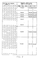
- Figure 2 illustrates schematically the table approach and shows how it can be truncated from all possible combinations that result from 7 sub-bands in the range 0 to 3500 hertz, the remainder from 3500 to 4000 being dropped for this example, and 32 absolute block peak energy levels.
- Each table is addressed by the 7 sub-band energy level numbers found in the sub-band peak energy determining phase. The other entry is the overall absolute energy level which falls within one of 32 levels previously noted.
- the entire table may be condensed to a table of 148 entries following the observance of the following rules.
- Step 1 the maximum of the sub-band numbers 0 and 1 is called band group 0.
- the maximum value of the sub-band peak numbers in sub-bands 2 and 3 is called band group 1.
- the maximum of the band numbers 4, 5 and 6 is called band group 2.
- the coarse groupings noted above are implemented in this table given a raw spectral distribution as follows for the energy peak levels in the sub-bands. Energy peaks might be represented as 4, 6, 2, 1, 3, 1 and 0 for the energy sub-bands 0 through 6 and the absolute block peak energy level might be decimal 4 or 00100 in binary.
- band group 0 comprises the measurements from the energy sub-band peaks 0 and 1, that band group 1 comprises the energy peaks from frequency sub-bands 2 and 3 and band group 2 comprises the energy peaks from frequency sub-bands 4, 5 and 6.
- the absolute energy level also can occupy several different states which were reduced to 4 states instead of 32 by a grouping as outlined earlier. Values of absolute energy level from 0 through 7 are assigned to state A. State B comprises the level 8 through 15; state C comprises the absolute energy levels from 16 through 23 and state D comprises the energy levels 24 through 31.
- the unique energy state defined in table 2 will be: Band group 0, which is the maximum of 4 and 6, will equal 6 and corresponds to state D. Band group 1, having a maximum of 2 and 1 will be 2 which corresponds to state A. Band group 2 having the maximum of 3, 1 and 0 will be 3 which corresponds to state B. The absolute energy level which is 4 corresponds to state A.
- the final location within the table is that defined by the coordinates DABA.
- the high quality table indices would be loaded with many 0 content locations indicating that no bits are to be dropped from the samples assuming that the original signal samples are the usual 16 bit 2's complement samples.
- the high quality table indices would be loaded with many 0 content locations indicating that no bits are to be dropped from the samples assuming that the original signal samples are the usual 16 bit 2's complement samples.
- it is possible to greatly reduce the overall transmission channel loading by dropping the least significant bits and indicating to the receiver how many of the least significant bits have been dropped from each sample during a given block transmission period. Two or three bits being dropped from each sample may create little or no noticeable distortion in the final received and reconstructed signal but deleting even one of the high order bits will produce serious distortion.
- the level of distortion that is acceptable is a subjective criteria based on the acceptability of the overall perceived signal to the human subject.
- a typical quality table of minimum acceptable resolution would require deletion of 0 to 6 bits from each sample while the highest quality table possible would dictate 0 bit deletion from each sample.
- quality tables may be established for any range of quality possible from the highest to the lowest acceptable quality level. It is equally clear that operation on a specific voice line to a specific user might be dictated as being accorded a high level of quality for priority communications but only a very low objective level of quality would be provided for machines such as a modem over the same line. The only difference in construction would be that different quality performance tables would be utilized depending on the nature of the input.
- a user wishing to acquire service over such a communication system might opt for high quality, high signal to noise transmission and be assigned a performance quality table with little or no bit deletion at a relatively higher price since proportionately more of the total channel bandwidth will be utilized in supplying high quality service and the consequent number of bits required to generate the high quality will occupy more of the channel space.
- the user might request the least expensive or least proportionate amount of channel bandwidth for use by a modem.
- a more usual scenario would be that the system such as shown in Figure 1 would implement the highest quality service for all users consistent with the total demand placed on the system by the number of users present given the channel bandwidth available to the system. Should either the channel bandwidth become restricted or reduced or the number of users increased, resort to lower quality transmission tables, i.e., assignment of fewer bits to each user can be easily accommodated by switching to a different speech quality table for the next and any ensuing sample blocks until either the user demand decreases or channel capacity is increased.
- band group 0 has a band group level value of less than 3 and band group 1 has a level value less than 3 then the spectrum address will be three times the band group 0 level plus the band group 1 level which will generate spectrum addresses 0 through 8. If band group 0 has a level less than 3 and band group 1 is a level of 3, then the spectrum address will be four times the band group 0 level plus the band group 2 level plus 9 which will generate spectrum addresses from 9 to 20. And if the band group 0 level equals 3, then the spectrum address will be four times band group 1 level plus the band group 2 level plus 21 which will generate the spectrum addresses from 21 to 36.
- the other entry to the table is from among the 32 levels of the block peak that were possible.
- the 32 levels were condensed to 4 ranges by dropping the least significant bit of the 5 bit block peak level which reduces its range to only 16 levels of 4dB separation each.
- the remaining 4 bit number is used to address a 16 address table containing only the numbers 0, 37, 74 and 111 as noted earlier.
- the actual extent between the dividing points in the table between the values 0, 37, 74 and 111 is determined empirically by letting users perceive the result and select the most acceptable perceived quality. However, it may be observed that with high energy levels, the overall perceived quality is highly subject to signal to noise ratio distortion and that at very low levels the signal to noise ratio is not very important in a perceived quality of speech.
- the steps are as follows.
- the incoming signal samples are divided into blocks.
- all the samples occurring within a 4 millisecond period are a block.
- the peak within the block i.e., the peak magnitude of all 32 signal samples in the 8 sub-bands with 4 signal samples per sub-band is found.
- Thirty-two logarithmic sized segments are established for the range of the block peak.
- the segment in which the given block peak is found is encoded as a 5 bit binary number representing the segment among the 32 in which it was found.
- a signal sample range is found lying within the upper bound of the block peak segment that has been identified for the given block peak.
- the main channel information i.e., the individual signal samples (all 32 of them) are transmitted.
- the number of bits used to represent each sample is truncated according to the value found in the table being utilized in accordance with this invention. In a gross simplification, if the minimum acceptable quality is being afforded, it may dictate that each of the signal samples transmitted may have its X lowest bits dropped where X is the value found in the table associated with the lowest acceptable quality of service. In actuality, the number of bits dropped will be different every 4 milliseconds. The various qualities simply result in different average number of bits dropped.
Landscapes
- Engineering & Computer Science (AREA)
- Computer Networks & Wireless Communication (AREA)
- Signal Processing (AREA)
- Compression, Expansion, Code Conversion, And Decoders (AREA)
- Transmission Systems Not Characterized By The Medium Used For Transmission (AREA)
Applications Claiming Priority (2)
| Application Number | Priority Date | Filing Date | Title |
|---|---|---|---|
| US900113 | 1986-08-25 | ||
| US06/900,113 US4899384A (en) | 1986-08-25 | 1986-08-25 | Table controlled dynamic bit allocation in a variable rate sub-band speech coder |
Publications (3)
| Publication Number | Publication Date |
|---|---|
| EP0259553A2 true EP0259553A2 (fr) | 1988-03-16 |
| EP0259553A3 EP0259553A3 (en) | 1989-06-07 |
| EP0259553B1 EP0259553B1 (fr) | 1993-02-10 |
Family
ID=25411991
Family Applications (1)
| Application Number | Title | Priority Date | Filing Date |
|---|---|---|---|
| EP87109393A Expired - Lifetime EP0259553B1 (fr) | 1986-08-25 | 1987-06-30 | Allocation dynamique commandée par table dans un codeur de parole à cadence variable |
Country Status (4)
| Country | Link |
|---|---|
| US (1) | US4899384A (fr) |
| EP (1) | EP0259553B1 (fr) |
| JP (1) | JPS6358500A (fr) |
| DE (1) | DE3784120T2 (fr) |
Cited By (7)
| Publication number | Priority date | Publication date | Assignee | Title |
|---|---|---|---|---|
| EP0464839A3 (en) * | 1990-07-05 | 1993-10-27 | Fujitsu Ltd | Digitally multiplexed transmission system |
| EP0674394A1 (fr) * | 1993-10-08 | 1995-09-27 | Sony Corporation | Processeur de signaux numeriques, procede de traitement de signaux numeriques et support d'enregistrement de donnees |
| EP0682337A1 (fr) * | 1993-11-29 | 1995-11-15 | Sony Corporation | Procede et appareil de codage/decodage d'un signal et support d'enregistrement |
| EP0708533A2 (fr) * | 1989-06-02 | 1996-04-24 | Koninklijke Philips Electronics N.V. | Signal de transmission |
| EP0728350B1 (fr) * | 1994-08-10 | 2003-03-26 | QUALCOMM Incorporated | Procede et appareil de selection d'un taux de codage dans un vocodeur a taux variable |
| EP1873945A2 (fr) * | 1996-09-19 | 2008-01-02 | BEARD, Terry D. | Appareil et procédé audio de cartographie spectrale multicanaux |
| CN104838443A (zh) * | 2012-12-13 | 2015-08-12 | 松下电器(美国)知识产权公司 | 语音声响编码装置、语音声响解码装置、语音声响编码方法及语音声响解码方法 |
Families Citing this family (36)
| Publication number | Priority date | Publication date | Assignee | Title |
|---|---|---|---|---|
| US5742735A (en) * | 1987-10-06 | 1998-04-21 | Fraunhofer Gesellschaft Zur Forderung Der Angewanten Forschung E.V. | Digital adaptive transformation coding method |
| US5150387A (en) * | 1989-12-21 | 1992-09-22 | Kabushiki Kaisha Toshiba | Variable rate encoding and communicating apparatus |
| JP2833212B2 (ja) * | 1990-11-29 | 1998-12-09 | 松下電器産業株式会社 | 帯域分割符号化のビット割当方法 |
| ES2166355T3 (es) * | 1991-06-11 | 2002-04-16 | Qualcomm Inc | Vocodificador de velocidad variable. |
| US5394508A (en) * | 1992-01-17 | 1995-02-28 | Massachusetts Institute Of Technology | Method and apparatus for encoding decoding and compression of audio-type data |
| US5369724A (en) * | 1992-01-17 | 1994-11-29 | Massachusetts Institute Of Technology | Method and apparatus for encoding, decoding and compression of audio-type data using reference coefficients located within a band of coefficients |
| TW235392B (fr) * | 1992-06-02 | 1994-12-01 | Philips Electronics Nv | |
| US5341456A (en) * | 1992-12-02 | 1994-08-23 | Qualcomm Incorporated | Method for determining speech encoding rate in a variable rate vocoder |
| US5479447A (en) * | 1993-05-03 | 1995-12-26 | The Board Of Trustees Of The Leland Stanford, Junior University | Method and apparatus for adaptive, variable bandwidth, high-speed data transmission of a multicarrier signal over digital subscriber lines |
| US5506866A (en) * | 1993-11-15 | 1996-04-09 | At&T Corp. | Side-channel communications in simultaneous voice and data transmission |
| US5764698A (en) * | 1993-12-30 | 1998-06-09 | International Business Machines Corporation | Method and apparatus for efficient compression of high quality digital audio |
| US5761636A (en) * | 1994-03-09 | 1998-06-02 | Motorola, Inc. | Bit allocation method for improved audio quality perception using psychoacoustic parameters |
| TW271524B (fr) | 1994-08-05 | 1996-03-01 | Qualcomm Inc | |
| US5864802A (en) * | 1995-09-22 | 1999-01-26 | Samsung Electronics Co., Ltd. | Digital audio encoding method utilizing look-up table and device thereof |
| US5956674A (en) * | 1995-12-01 | 1999-09-21 | Digital Theater Systems, Inc. | Multi-channel predictive subband audio coder using psychoacoustic adaptive bit allocation in frequency, time and over the multiple channels |
| KR100648475B1 (ko) * | 1996-01-29 | 2007-01-31 | 소니 가부시끼 가이샤 | 통신자원할당방법및장치 |
| CN1106085C (zh) * | 1996-04-26 | 2003-04-16 | 德国汤姆逊-布朗特公司 | 对数字音频信号编码的方法和装置 |
| US5751901A (en) * | 1996-07-31 | 1998-05-12 | Qualcomm Incorporated | Method for searching an excitation codebook in a code excited linear prediction (CELP) coder |
| DE19727938B4 (de) * | 1997-07-01 | 2006-12-14 | Mayah Communications Gmbh | Verfahren und Vorrichtung zum Codieren von Signalen |
| US6084917A (en) | 1997-12-16 | 2000-07-04 | Integrated Telecom Express | Circuit for configuring and dynamically adapting data and energy parameters in a multi-channel communications system |
| US6094459A (en) * | 1997-12-16 | 2000-07-25 | Integrated Telecom Express | Circuit for configuring data and energy parameters in a multi-channel communications system |
| US6128348A (en) * | 1997-12-16 | 2000-10-03 | Integrated Telecom Express | Method for configuring data and energy parameters in a multi-channel communications system |
| US6075821A (en) * | 1997-12-16 | 2000-06-13 | Integrated Telecom Express | Method of configuring and dynamically adapting data and energy parameters in a multi-channel communications system |
| US6084906A (en) * | 1997-12-17 | 2000-07-04 | Integrated Telecom Express | ADSL transceiver implemented with associated bit and energy loading integrated circuit |
| US6691084B2 (en) | 1998-12-21 | 2004-02-10 | Qualcomm Incorporated | Multiple mode variable rate speech coding |
| JP3580777B2 (ja) * | 1998-12-28 | 2004-10-27 | フラウンホーファー−ゲゼルシャフト・ツール・フェルデルング・デル・アンゲヴァンテン・フォルシュング・アインゲトラーゲネル・フェライン | オーディオ信号又はビットストリームの符号化又は復号化のための方法及び装置 |
| FR2791166B1 (fr) * | 1999-03-17 | 2003-01-10 | Matra Nortel Communications | Procedes de codage, de decodage et de transcodage |
| AU3078501A (en) * | 1999-11-08 | 2001-06-06 | Ericsson Inc. | Integrated voice and data transmission based on bit importance ranking |
| US6369722B1 (en) | 2000-03-17 | 2002-04-09 | Matra Nortel Communications | Coding, decoding and transcoding methods |
| JP2005071522A (ja) * | 2003-08-27 | 2005-03-17 | Sony Corp | コンテンツ再生方法、コンテンツ再生装置およびコンテンツ配信方法 |
| KR20050028193A (ko) * | 2003-09-17 | 2005-03-22 | 삼성전자주식회사 | 오디오 신호에 적응적으로 부가 정보를 삽입하기 위한방법, 오디오 신호에 삽입된 부가 정보의 재생 방법, 및그 장치와 이를 구현하기 위한 프로그램이 기록된 기록 매체 |
| CN101989428B (zh) * | 2009-07-31 | 2012-07-04 | 华为技术有限公司 | 比特分配方法、编码方法、解码方法、编码器及解码器 |
| US8924222B2 (en) | 2010-07-30 | 2014-12-30 | Qualcomm Incorporated | Systems, methods, apparatus, and computer-readable media for coding of harmonic signals |
| US9208792B2 (en) | 2010-08-17 | 2015-12-08 | Qualcomm Incorporated | Systems, methods, apparatus, and computer-readable media for noise injection |
| FR2973551A1 (fr) * | 2011-03-29 | 2012-10-05 | France Telecom | Allocation par sous-bandes de bits de quantification de parametres d'information spatiale pour un codage parametrique |
| AU2012256550B2 (en) * | 2011-05-13 | 2016-08-25 | Samsung Electronics Co., Ltd. | Bit allocating, audio encoding and decoding |
Citations (4)
| Publication number | Priority date | Publication date | Assignee | Title |
|---|---|---|---|---|
| US4386237A (en) * | 1980-12-22 | 1983-05-31 | Intelsat | NIC Processor using variable precision block quantization |
| EP0084125A2 (fr) * | 1982-01-15 | 1983-07-27 | International Business Machines Corporation | Appareil pour le multiplexage statistique efficace de signaux de parole et de données |
| EP0085820A1 (fr) * | 1982-02-09 | 1983-08-17 | International Business Machines Corporation | Procédé de transmission numérique multi-vitesses et dispositif de mise en oeuvre dudit procédé |
| US4535472A (en) * | 1982-11-05 | 1985-08-13 | At&T Bell Laboratories | Adaptive bit allocator |
Family Cites Families (7)
| Publication number | Priority date | Publication date | Assignee | Title |
|---|---|---|---|---|
| FR2389277A1 (fr) * | 1977-04-29 | 1978-11-24 | Ibm France | Procede de quantification a allocation dynamique du taux de bits disponible, et dispositif de mise en oeuvre dudit procede |
| JPS542050A (en) * | 1977-06-07 | 1979-01-09 | Nec Corp | Block coding and decoding system |
| FR2412987A1 (fr) * | 1977-12-23 | 1979-07-20 | Ibm France | Procede de compression de donnees relatives au signal vocal et dispositif mettant en oeuvre ledit procede |
| JPS5921039B2 (ja) * | 1981-11-04 | 1984-05-17 | 日本電信電話株式会社 | 適応予測符号化方式 |
| JPS58193598A (ja) * | 1982-05-07 | 1983-11-11 | 日本電気株式会社 | 音声符号化方式とそれに供する装置 |
| CA1253255A (fr) * | 1983-05-16 | 1989-04-25 | Nec Corporation | Systeme de codage et de decodage simultanee de signaux multiples |
| GB8421498D0 (en) * | 1984-08-24 | 1984-09-26 | British Telecomm | Frequency domain speech coding |
-
1986
- 1986-08-25 US US06/900,113 patent/US4899384A/en not_active Expired - Fee Related
-
1987
- 1987-05-15 JP JP62117250A patent/JPS6358500A/ja active Pending
- 1987-06-30 DE DE8787109393T patent/DE3784120T2/de not_active Expired - Fee Related
- 1987-06-30 EP EP87109393A patent/EP0259553B1/fr not_active Expired - Lifetime
Patent Citations (4)
| Publication number | Priority date | Publication date | Assignee | Title |
|---|---|---|---|---|
| US4386237A (en) * | 1980-12-22 | 1983-05-31 | Intelsat | NIC Processor using variable precision block quantization |
| EP0084125A2 (fr) * | 1982-01-15 | 1983-07-27 | International Business Machines Corporation | Appareil pour le multiplexage statistique efficace de signaux de parole et de données |
| EP0085820A1 (fr) * | 1982-02-09 | 1983-08-17 | International Business Machines Corporation | Procédé de transmission numérique multi-vitesses et dispositif de mise en oeuvre dudit procédé |
| US4535472A (en) * | 1982-11-05 | 1985-08-13 | At&T Bell Laboratories | Adaptive bit allocator |
Non-Patent Citations (1)
| Title |
|---|
| IEEE INTERNATIONAL CONFERENCE ON ACOUSTICS, SPEECH AND SIGNAL PROCESSING ICASSP '86, Tokyo, 7th - 11th April 1986, vol. 4, pages 3079-3082, IEEE, Tokyo, JP; L.M. LUNDHEIM et al.: "Variable rate coding speech for storage" * |
Cited By (44)
| Publication number | Priority date | Publication date | Assignee | Title |
|---|---|---|---|---|
| EP0708533A2 (fr) * | 1989-06-02 | 1996-04-24 | Koninklijke Philips Electronics N.V. | Signal de transmission |
| EP0708533A3 (fr) * | 1989-06-02 | 1999-08-04 | Koninklijke Philips Electronics N.V. | Signal de transmission |
| EP0464839A3 (en) * | 1990-07-05 | 1993-10-27 | Fujitsu Ltd | Digitally multiplexed transmission system |
| US5436899A (en) * | 1990-07-05 | 1995-07-25 | Fujitsu Limited | High performance digitally multiplexed transmission system |
| EP0674394A1 (fr) * | 1993-10-08 | 1995-09-27 | Sony Corporation | Processeur de signaux numeriques, procede de traitement de signaux numeriques et support d'enregistrement de donnees |
| EP0674394A4 (fr) * | 1993-10-08 | 1998-10-21 | Sony Corp | Processeur de signaux numeriques, procede de traitement de signaux numeriques et support d'enregistrement de donnees. |
| EP0682337A1 (fr) * | 1993-11-29 | 1995-11-15 | Sony Corporation | Procede et appareil de codage/decodage d'un signal et support d'enregistrement |
| EP0682337A4 (fr) * | 1993-11-29 | 1998-09-16 | Sony Corp | Procede et appareil de codage/decodage d'un signal et support d'enregistrement. |
| EP0728350B1 (fr) * | 1994-08-10 | 2003-03-26 | QUALCOMM Incorporated | Procede et appareil de selection d'un taux de codage dans un vocodeur a taux variable |
| EP1233408B1 (fr) * | 1994-08-10 | 2004-12-22 | QUALCOMM Incorporated | Procédé et appareil de sélection d'un taux de codage dans un vocodeur à taux variable |
| EP1424686A3 (fr) * | 1994-08-10 | 2006-03-22 | QUALCOMM Incorporated | Procédé et appareil de sélection d'un taux de codage dans un vocodeur à taux variable |
| US7792305B2 (en) | 1996-09-19 | 2010-09-07 | Terry D. Beard | Multichannel spectral mapping audio apparatus and method |
| US7864965B2 (en) | 1996-09-19 | 2011-01-04 | Terry D. Beard | Multichannel spectral mapping audio apparatus and method |
| US7769178B2 (en) | 1996-09-19 | 2010-08-03 | Terry D. Beard | Multichannel spectral mapping audio apparatus and method |
| US7769180B2 (en) | 1996-09-19 | 2010-08-03 | Terry D. Beard | Multichannel spectral mapping audio apparatus and method |
| US7769179B2 (en) | 1996-09-19 | 2010-08-03 | Terry D. Beard | Multichannel spectral mapping audio apparatus and method |
| US7769181B2 (en) | 1996-09-19 | 2010-08-03 | Terry D. Beard | Multichannel spectral mapping audio apparatus and method |
| US7773758B2 (en) | 1996-09-19 | 2010-08-10 | Terry D. Beard | Multichannel spectral mapping audio apparatus and method |
| US7773757B2 (en) | 1996-09-19 | 2010-08-10 | Terry D. Beard | Multichannel spectral mapping audio apparatus and method |
| US7773756B2 (en) | 1996-09-19 | 2010-08-10 | Terry D. Beard | Multichannel spectral mapping audio encoding apparatus and method with dynamically varying mapping coefficients |
| US7783052B2 (en) | 1996-09-19 | 2010-08-24 | Terry D. Beard | Multichannel spectral mapping audio apparatus and method |
| US7792308B2 (en) | 1996-09-19 | 2010-09-07 | Terry D. Beard | Multichannel spectral mapping audio apparatus and method |
| EP1873945A2 (fr) * | 1996-09-19 | 2008-01-02 | BEARD, Terry D. | Appareil et procédé audio de cartographie spectrale multicanaux |
| US7792304B2 (en) | 1996-09-19 | 2010-09-07 | Terry D. Beard | Multichannel spectral mapping audio apparatus and method |
| US7792306B2 (en) | 1996-09-19 | 2010-09-07 | Terry D. Beard | Multichannel spectral mapping audio apparatus and method |
| US7792307B2 (en) | 1996-09-19 | 2010-09-07 | Terry D. Beard | Multichannel spectral mapping audio apparatus and method |
| US7796765B2 (en) | 1996-09-19 | 2010-09-14 | Terry D. Beard | Multichannel spectral mapping audio apparatus and method |
| US7864966B2 (en) | 1996-09-19 | 2011-01-04 | Terry D. Beard | Multichannel spectral mapping audio apparatus and method |
| EP1873945A3 (fr) * | 1996-09-19 | 2010-04-07 | BEARD, Terry D. | Appareil et procédé audio de cartographie spectrale multicanaux |
| US7864964B2 (en) | 1996-09-19 | 2011-01-04 | Terry D. Beard | Multichannel spectral mapping audio apparatus and method |
| US7873171B2 (en) | 1996-09-19 | 2011-01-18 | Terry D. Beard | Multichannel spectral mapping audio apparatus and method |
| US7876905B2 (en) | 1996-09-19 | 2011-01-25 | Terry D. Beard | Multichannel spectral mapping audio apparatus and method |
| US7965849B2 (en) | 1996-09-19 | 2011-06-21 | Terry D. Beard | Multichannel spectral mapping audio apparatus and method |
| US8014535B2 (en) | 1996-09-19 | 2011-09-06 | Terry D. Beard | Multichannel spectral vector mapping audio apparatus and method |
| US8027480B2 (en) | 1996-09-19 | 2011-09-27 | Terry D. Beard | Multichannel spectral mapping audio apparatus and method |
| US8300833B2 (en) | 1996-09-19 | 2012-10-30 | Terry D. Beard | Multichannel spectral mapping audio apparatus and method with dynamically varying mapping coefficients |
| CN104838443A (zh) * | 2012-12-13 | 2015-08-12 | 松下电器(美国)知识产权公司 | 语音声响编码装置、语音声响解码装置、语音声响编码方法及语音声响解码方法 |
| EP2933799A4 (fr) * | 2012-12-13 | 2016-01-13 | Panasonic Ip Corp America | Dispositif de codage audio vocal, dispositif de décodage audio vocal, procédé de codage audio vocal et procédé de décodage audio vocal |
| US9767815B2 (en) | 2012-12-13 | 2017-09-19 | Panasonic Intellectual Property Corporation Of America | Voice audio encoding device, voice audio decoding device, voice audio encoding method, and voice audio decoding method |
| CN104838443B (zh) * | 2012-12-13 | 2017-09-22 | 松下电器(美国)知识产权公司 | 语音声响编码装置、语音声响解码装置、语音声响编码方法及语音声响解码方法 |
| EP3232437A1 (fr) * | 2012-12-13 | 2017-10-18 | Panasonic Intellectual Property Corporation of America | Dispositif de codage audio vocal, dispositif de décodage audio vocal, procédé de codage audio vocal et procédé de décodage audio vocal |
| US10102865B2 (en) | 2012-12-13 | 2018-10-16 | Fraunhofer-Gesellschaft Zur Foerderung Der Angewandten Forschung E.V. | Voice audio encoding device, voice audio decoding device, voice audio encoding method, and voice audio decoding method |
| EP3457400A1 (fr) * | 2012-12-13 | 2019-03-20 | FRAUNHOFER-GESELLSCHAFT zur Förderung der angewandten Forschung e.V. | Dispositif de codage audio vocal, dispositif de décodage audio vocal, procédé de codage audio vocal et procédé de décodage audio vocal |
| US10685660B2 (en) | 2012-12-13 | 2020-06-16 | Fraunhofer-Gesellschaft Zur Foerderung Der Angewandten Forschung E.V. | Voice audio encoding device, voice audio decoding device, voice audio encoding method, and voice audio decoding method |
Also Published As
| Publication number | Publication date |
|---|---|
| EP0259553B1 (fr) | 1993-02-10 |
| US4899384A (en) | 1990-02-06 |
| JPS6358500A (ja) | 1988-03-14 |
| EP0259553A3 (en) | 1989-06-07 |
| DE3784120D1 (de) | 1993-03-25 |
| DE3784120T2 (de) | 1993-08-12 |
Similar Documents
| Publication | Publication Date | Title |
|---|---|---|
| US4899384A (en) | Table controlled dynamic bit allocation in a variable rate sub-band speech coder | |
| CN1046608C (zh) | 采用加权信号量化位分配进行数据压缩的装置和方法 | |
| JP2732854B2 (ja) | ディジタルオーディオ信号のサブバンド符号化用ディジタルシステム | |
| CN1032102C (zh) | 数字音频信号的编码方法 | |
| JP4046766B2 (ja) | 高速度データを圧縮し伝送する方法および装置 | |
| AU676444B2 (en) | Method, device, and systems for determining a masking level for a subband in a subband audio encoder | |
| US4790015A (en) | Multirate digital transmission method and device for implementing said method | |
| US5559900A (en) | Compression of signals for perceptual quality by selecting frequency bands having relatively high energy | |
| JPH07210195A (ja) | 高品質ディジタル・オーディオの効率的な圧縮のための方法および装置 | |
| JPH09500503A (ja) | 適応ビット配分符号化装置及び方法 | |
| US5588024A (en) | Frequency subband encoding apparatus | |
| JPH0474018A (ja) | 適応ビット割当て方法及び装置 | |
| US5353375A (en) | Digital audio signal coding method through allocation of quantization bits to sub-band samples split from the audio signal | |
| JPH09134200A (ja) | ディジタル・オーディオ符号化方法及びその装置 | |
| JP2858122B2 (ja) | デジタル適応変換符号化方法 | |
| JP2000151413A (ja) | オーディオ符号化における適応ダイナミック可変ビット割り当て方法 | |
| KR960003628B1 (ko) | 디지탈신호의 부호화/복호화 방법 및 장치 | |
| JP3276370B2 (ja) | N個の信号源からの信号の同時伝送方法 | |
| JPH08307281A (ja) | 非線形量子化方法及び非線形逆量子化方法 | |
| KR100300957B1 (ko) | 룩업테이블을이용한디지탈오디오부호화방법및장치 | |
| KR100246376B1 (ko) | 서브밴드 부호화기의 적응비트 할당장치 | |
| KR0152016B1 (ko) | 가변 비트할당을 이용한 부호화 및 복호화시스템 | |
| JPH07295594A (ja) | オーディオ信号符号化方法 | |
| JP3011447B2 (ja) | 帯域分割符号化装置 | |
| JPH0750589A (ja) | サブバンド符号化装置 |
Legal Events
| Date | Code | Title | Description |
|---|---|---|---|
| PUAI | Public reference made under article 153(3) epc to a published international application that has entered the european phase |
Free format text: ORIGINAL CODE: 0009012 |
|
| AK | Designated contracting states |
Kind code of ref document: A2 Designated state(s): DE FR GB IT |
|
| 17P | Request for examination filed |
Effective date: 19880616 |
|
| PUAL | Search report despatched |
Free format text: ORIGINAL CODE: 0009013 |
|
| AK | Designated contracting states |
Kind code of ref document: A3 Designated state(s): DE FR GB IT |
|
| 17Q | First examination report despatched |
Effective date: 19910807 |
|
| GRAA | (expected) grant |
Free format text: ORIGINAL CODE: 0009210 |
|
| AK | Designated contracting states |
Kind code of ref document: B1 Designated state(s): DE FR GB IT |
|
| REF | Corresponds to: |
Ref document number: 3784120 Country of ref document: DE Date of ref document: 19930325 |
|
| ITF | It: translation for a ep patent filed |
Owner name: IBM - DR. ING. FABRIZIO LETTIERI |
|
| PGFP | Annual fee paid to national office [announced via postgrant information from national office to epo] |
Ref country code: GB Payment date: 19930525 Year of fee payment: 7 |
|
| PGFP | Annual fee paid to national office [announced via postgrant information from national office to epo] |
Ref country code: FR Payment date: 19930601 Year of fee payment: 7 |
|
| ET | Fr: translation filed | ||
| PGFP | Annual fee paid to national office [announced via postgrant information from national office to epo] |
Ref country code: DE Payment date: 19930712 Year of fee payment: 7 |
|
| PLBE | No opposition filed within time limit |
Free format text: ORIGINAL CODE: 0009261 |
|
| STAA | Information on the status of an ep patent application or granted ep patent |
Free format text: STATUS: NO OPPOSITION FILED WITHIN TIME LIMIT |
|
| 26N | No opposition filed | ||
| PG25 | Lapsed in a contracting state [announced via postgrant information from national office to epo] |
Ref country code: GB Effective date: 19940630 |
|
| PG25 | Lapsed in a contracting state [announced via postgrant information from national office to epo] |
Ref country code: FR Effective date: 19950228 |
|
| GBPC | Gb: european patent ceased through non-payment of renewal fee |
Effective date: 19940630 |
|
| PG25 | Lapsed in a contracting state [announced via postgrant information from national office to epo] |
Ref country code: DE Effective date: 19950301 |
|
| REG | Reference to a national code |
Ref country code: FR Ref legal event code: ST |
|
| PG25 | Lapsed in a contracting state [announced via postgrant information from national office to epo] |
Ref country code: IT Free format text: LAPSE BECAUSE OF NON-PAYMENT OF DUE FEES;WARNING: LAPSES OF ITALIAN PATENTS WITH EFFECTIVE DATE BEFORE 2007 MAY HAVE OCCURRED AT ANY TIME BEFORE 2007. THE CORRECT EFFECTIVE DATE MAY BE DIFFERENT FROM THE ONE RECORDED. Effective date: 20050630 |