EP0246098A2 - Transporting system of floated carrier type - Google Patents
Transporting system of floated carrier type Download PDFInfo
- Publication number
- EP0246098A2 EP0246098A2 EP87304290A EP87304290A EP0246098A2 EP 0246098 A2 EP0246098 A2 EP 0246098A2 EP 87304290 A EP87304290 A EP 87304290A EP 87304290 A EP87304290 A EP 87304290A EP 0246098 A2 EP0246098 A2 EP 0246098A2
- Authority
- EP
- European Patent Office
- Prior art keywords
- carrier
- power control
- zero power
- exciting current
- rail
- Prior art date
- Legal status (The legal status is an assumption and is not a legal conclusion. Google has not performed a legal analysis and makes no representation as to the accuracy of the status listed.)
- Granted
Links
Images


Classifications
-
- H—ELECTRICITY
- H02—GENERATION; CONVERSION OR DISTRIBUTION OF ELECTRIC POWER
- H02N—ELECTRIC MACHINES NOT OTHERWISE PROVIDED FOR
- H02N15/00—Holding or levitation devices using magnetic attraction or repulsion, not otherwise provided for
-
- B—PERFORMING OPERATIONS; TRANSPORTING
- B65—CONVEYING; PACKING; STORING; HANDLING THIN OR FILAMENTARY MATERIAL
- B65G—TRANSPORT OR STORAGE DEVICES, e.g. CONVEYORS FOR LOADING OR TIPPING, SHOP CONVEYOR SYSTEMS OR PNEUMATIC TUBE CONVEYORS
- B65G54/00—Non-mechanical conveyors not otherwise provided for
- B65G54/02—Non-mechanical conveyors not otherwise provided for electrostatic, electric, or magnetic
-
- B—PERFORMING OPERATIONS; TRANSPORTING
- B60—VEHICLES IN GENERAL
- B60L—PROPULSION OF ELECTRICALLY-PROPELLED VEHICLES; SUPPLYING ELECTRIC POWER FOR AUXILIARY EQUIPMENT OF ELECTRICALLY-PROPELLED VEHICLES; ELECTRODYNAMIC BRAKE SYSTEMS FOR VEHICLES IN GENERAL; MAGNETIC SUSPENSION OR LEVITATION FOR VEHICLES; MONITORING OPERATING VARIABLES OF ELECTRICALLY-PROPELLED VEHICLES; ELECTRIC SAFETY DEVICES FOR ELECTRICALLY-PROPELLED VEHICLES
- B60L13/00—Electric propulsion for monorail vehicles, suspension vehicles or rack railways; Magnetic suspension or levitation for vehicles
- B60L13/04—Magnetic suspension or levitation for vehicles
- B60L13/06—Means to sense or control vehicle position or attitude with respect to railway
-
- B—PERFORMING OPERATIONS; TRANSPORTING
- B60—VEHICLES IN GENERAL
- B60L—PROPULSION OF ELECTRICALLY-PROPELLED VEHICLES; SUPPLYING ELECTRIC POWER FOR AUXILIARY EQUIPMENT OF ELECTRICALLY-PROPELLED VEHICLES; ELECTRODYNAMIC BRAKE SYSTEMS FOR VEHICLES IN GENERAL; MAGNETIC SUSPENSION OR LEVITATION FOR VEHICLES; MONITORING OPERATING VARIABLES OF ELECTRICALLY-PROPELLED VEHICLES; ELECTRIC SAFETY DEVICES FOR ELECTRICALLY-PROPELLED VEHICLES
- B60L13/00—Electric propulsion for monorail vehicles, suspension vehicles or rack railways; Magnetic suspension or levitation for vehicles
- B60L13/10—Combination of electric propulsion and magnetic suspension or levitation
-
- B—PERFORMING OPERATIONS; TRANSPORTING
- B61—RAILWAYS
- B61C—LOCOMOTIVES; MOTOR RAILCARS
- B61C11/00—Locomotives or motor railcars characterised by the type of means applying the tractive effort; Arrangement or disposition of running gear other than normal driving wheel
-
- B—PERFORMING OPERATIONS; TRANSPORTING
- B60—VEHICLES IN GENERAL
- B60L—PROPULSION OF ELECTRICALLY-PROPELLED VEHICLES; SUPPLYING ELECTRIC POWER FOR AUXILIARY EQUIPMENT OF ELECTRICALLY-PROPELLED VEHICLES; ELECTRODYNAMIC BRAKE SYSTEMS FOR VEHICLES IN GENERAL; MAGNETIC SUSPENSION OR LEVITATION FOR VEHICLES; MONITORING OPERATING VARIABLES OF ELECTRICALLY-PROPELLED VEHICLES; ELECTRIC SAFETY DEVICES FOR ELECTRICALLY-PROPELLED VEHICLES
- B60L2200/00—Type of vehicles
- B60L2200/26—Rail vehicles
Definitions
- the present invention relates to a transporting system of floated carrier type for transporting small cargo and, more particularly, to a transporting system of floated carrier type capable of reducing an impact acting on a carrier itself or cargo loaded thereon when the carrier is ceased to be floated.
- a carrier system As one method of office automation, a carrier system has been recently widely used to transport slips, documents, cash, materials, and the like between a plurality of stations in a building.
- a carrier system used for such an application must be able to transport cargo rapidly without noise. For this reason, in a carrier system of this type, a carrier is generally suspended under and transported along guide rails in a noncontacting manner.
- a system of magnetically suspending or floating a carrier in a noncontacting manner has advantages such as a good following property with respect to guide rails and an effect of preventing noise and dust.
- a stopper may be provided at a station to fix the carrier so that the floating carrier is not shaken.
- such a stopper must not contact the carrier when the carrier simply passes through the station, thereby rendering a mechanism around the station complex in structure.
- the carrier may be attracted to be fixed on the guide rails or land on auxiliary rails during the loading/unloading operation.
- an exciting current supplied to a magnetic unit is controlled to be normally zero. Therefore, unlike a conventional magnetic floating control without a zero power feed-back loop, even if a target value of a gap length between the guide rails and the electromagnets is varied, an actual gap length cannot be varied because it is uniquely determined by the weights of the carrier and the cargo. For this reason, in order to, e.g., attract the carrier on the guide rails, power sources of the electromagnets and a control circuit must be turned off during magnetic floating.
- the carrier can not be fixed to the guide rail or released from the guide rail without the large impact between the guide or auxiliary rails and the carrier when the landing or floating of carrier is started, thereby undesirably destroying the cargo or the carrier or generating dust.
- a transporting system of floated carrier type capable of reducing an impact acting on a transporting carrier when the carrier is landed on guide rails or is started to be floated thereby protecting the cargo and the carrier and preventing generation of dust.
- a transporting system for transporting cargo to a predetermined position comprising:
- reference numeral 11 denotes a guide frame having an inverted U-shaped cross section and so disposed as to avoid obstacles in an office space and the like.
- Two guide rails 12a and 12b are disposed parallel to each other on the lower surface of an upper wall of frame 11, and emergency rails 13a and 13b each having a U-shaped cross section are disposed on the inner surfaces of side walls of frame 11. Open sides of rails 13a and 13b oppose each other.
- Carrier 15 is disposed below rails 12a and 12b so as to run along rails 12a and 12b.
- stator 16 of a linear induction motor is disposed on the lower surface of the upper wall of frame 11 and between rails 12a and 12b.
- Stator 16 is disposed along rails 12a and 12b and spaced apart therefrom by a predetermined distance.
- Each of rails 12a and 12b is obtained by painting plate-like member 21 made of a ferromagnetic material in white so as to improve reflection of a light beam from gap sensor 34, and has a split structure for facilitating installation in an office. Joint portion A of member 21 is subjected to predetermined joint processing.
- An arrangement of carrier 15 will now be described below. That is, plate-like base 25 is disposed to oppose the lower surfaces of rails 12a and 12b.
- Base 25 is constituted by split plates 26a and 26b disposed along the running direction, and connecting mechanism 27 for connecting plates 26a and 26b so that plates 26a and 26b can swing in a plane perpendicular to the running direction, i.e., about the running direction.
- Magnetic floating units 31 are disposed at the four corners of the upper surface of base 25, respectively. Each unit 31 is mounted on the upper surface of base 25 by bolt 32 and seat 33. Optical gap sensor 34 is mounted on unit 31 to detect a gap length between unit 31 and the lower surfaces of rails 12a and 12b.
- vessels 37 and 38 for accommodating cargo are mounted on the lower surfaces of plates 26a and 26b through connecting members 35a and 35b, and 36a and 35b, respectively.
- Each of vessels 37 and 38 has two control units 41 for controlling four units 31, two regulators or constant-voltage generators 42, and two small-capacity power sources 43 for supplying electric power to units 41 and generators 42.
- first to seventh phototransistors 46 are disposed at predetermined positions on the upper surface of base 25 to transmit a command from the guide rails to a control system mounted on carrier 15. Phototransistors 46 are so disposed as to oppose 7 LEDs (Light-Emitting Diodes) 47 mounted on the guide frame at a station in a predetermined position.
- base 25 also serves as a reaction plate as an operation element of the above-mentioned linear induction motor. When the system is in operation, base 25 is so disposed as to oppose stator 16 through a slight gap and supplied with a propulsive force therefrom.
- Each unit 31 is constituted by two electromagnets 51 and 52 and permanent magnet 53, as shown in Fig. 4.
- Electromagnets 51 and 52 are disposed along a direction perpendicular to the running direction of carrier 15 so as to oppose the lower end portions of rails 12a and 12b.
- Permanent magnet 53 is interposed between the lower side surfaces of electromagnets 51 and 52, and has a U shape as a whole.
- Each of electromagnets 51 and 52 is constituted by yoke 55 made of a ferromagnetic material, and coil 56 wound around yoke 55. Coils 56 of electromagnets 51 and 52 are connected in series with each other in a direction along which magnetic fluxes generated by electromagnets 51 and 52 are added with each other.
- Magnetic reluctance Rm of the magnetic circuit is represented by the followina eauation (1): where o is vacuum permeability; S, a cross-sectional area of the magnetic circuit; z, a gap length; ⁇ s, nonpermeability of portions excluding the gap; and l, a magnetic circuit length excluding the gap.
- total attractive force F acting between rails 12a and 12b and yokes 55 is represented by the following equation (3): Assuming that a direction represented by z is a gravity direction as shown in Fig. 4, an equation of motion is obtained as follows: where m is a total mass of a load acting on the magnetic floating portion and the magnetic floating portion; g, acceleration of gravity; and Um, an external force acting on the carrier.
- interlinked magnetic flux number ⁇ N of coils 56 connected in series with each other is:
- equation (9) is represented by following equation (10):
- a linear system represented by equation (9) is generally an unstable system.
- the system can be stabilized.
- C is an output matrix (in this case, a unit matrix)
- voltage E is represented by following equation (11):
- units 31 are subjected to the feed-back control so as to set the steady deviation of current to be zero regardless of the presence/absence of step-like external force Um.
- the following control methods had been proposed in U.S. Serial No. 726, 975, filed April, 25, 1985:
- Method 3 is used in an example described hereinafter to explain a method of varying the steady deviation of the gap length and a method of finally fixing the carrier.
- Fig. 6 is a block diagram of the magnetic floating system adopting method 3. That is, according to the above method, the system includes, in addition to compensator C 2 , integrating compensator C 3 , target value generators C 4 and C 5 , and a means for arbitrarily disabling compensator C 3 .
- Characteristic roots of functions G(s), H(s), P(s), and Q(s) can be obtained when A 4 (s) given by equation (24) is O, and the magnetic floating system of Fig. 6 can be stabilized by determining Fi, F 2 , F 3 , and F 4 .
- control is performed such that exciting current target value r 3 is gradually varied from zero to a predetermined value only when the floating carrier is to be fixed on the guide rails. In this case, soft landing of the carrier can be realized without abruptly stopping zero power feed-back.
- the above method is not used when the carrier fixed on the guide rails is to be softly floated.
- the control unit 41 is operated as if a counter force with respect to carrier 15 from rails 12a and 12b or rails 13a and 13b is an external force acting on carrier 15, thereby disabling start of floating of carrier 15.
- an operation of the zero power feed-back loop is stopped, and carrier 15 is gradually floated by gradually varying gap length target value Z D or added voltage eo from a predetermined value to another value as described above. Immediately after that, the operation of the zero power feed-back loop may be started.
- Unit 41 is constituted by sensor section 61 for detecting a magnetomotive force and magnetic reluctance generated in the magnetic circuit by units 31, and changes in motion of carrier 15, operation circuit 62 for calculating electric power to be supplies to coils 56 in accordance with a signal from section 61, and power amplifier 63 for supplying electric power to coils 56 in accordance with a signal from circuit 62.
- Electric power from source 43 is supplied to amplifier 63 through main switch 64 and switch 65.
- Electric power from source 43 is also supplied to circuit 62 and section 61 through switch 64, generator 42, and switch 66.
- Generator 42 is constituted by reference voltage generator 42a and current amplifier 42b, and outputs a constant voltage.
- the constant voltage from generator 42 is also supplied to actuator 67. Outputs from actuator 67 are supplied as command signals to switched 65 and 66, and circuit 62.
- Sensor section 61 is constituted by modulating circuit 68 for modulating a signal from sensor 34 so as to suppress an effect of external noise, and current detector 69 for detecting a current value of coils 56.
- Operation circuit 62 realizes the feed-back magmetic floating system in Fig. 6.
- gap length set value Z D from generator 70 is subtracted from a gap length detected by sensor 34 by subtracter 71.
- Outputs from subtracter 71 are supplied to feed-back gain compensators 73 and 74 directly and through differentiator 72, respectively.
- a current detection signal from detector 69 is supplied to fed-back gain compensator 75.
- Compensated outputs from compensators 73 to 75 are added by adder 76 and the sum is then supplied to one input terminal of subtracter 77.
- the current detection signal is compared with a current target value ("0" in a floating control state) from target value generator 79 in subtracter 78.
- a comparison result is supplied to integrating compensator 81 through switch unit 80, integration-compensated therein, and then supplied to the other input terminal of subtracter 77. Then, the output from subtracter 77 is used for gain adjustment of amplifier 63. Therefore, zero power feed-back loop L consisting of subtracter 78, compensator 81 and subtracter 77 is constituted.
- switch unit 80 serves to selectively stop function of compensator 81 in accordance with a command from actuator 67.
- unit 80 may be arranged such that capacitor C, connected between the input and output terminals of operation amplifier 82 constituting compensator 81, is short-circuited in accordance with an output from actuator 67.
- gain K 3 -1/RC of compensator 81 becomes 0 in accordance with the output from actuator 67, and the output from amplifier 82 also becomes 0.
- generators 70 and 79 vary their target values in accordance with the output from actuator 67.
- Generators 70 and 79 may be constituted as shown in Figs. 9A and 9B, respectively. That is, generator 70 is constituted such that switch 86 is provided between the input and output terminals of a filter constituting a primary delay system consisting of amplifier 84, resistor Rb, and capacitor Cb.
- Generator 79 is similarly constituted such that switch 85 is provided between the input and output terminals of a filter constituting a primary delay system consisting of amplifier 83, resistor Ra, and capacitor Ca. Switches 85 and 86 are opened/closed in accordance with the output from actuator 67.
- Generators 70 and 79 receive predetermined input values When switches 85 and 86 are switched from closed to open states, generators 70 and 79 output target values gradually varying from the predetermined value to other values.
- Actuator 67 is constituted by external command converter 91 and switching signal generator 92, as shown in Fig. 10.
- Converter 91 is constituted by energizing circuit 93 for supplying an exciting current to the seven LEDs 47 in a guide rail side to drive LEDs 47 mounted on frame 11 in accordance with the external command, LEDs 47 mounted on frame 11, seven phototransistors 46 connected to constant-voltage generator 42 and mounted in positions corresponding to LEDs 47 of carrier 15 at a station, and voltage generator 94 for outputting a binary-value voltage in accordance with outputs from central five phototransistors 46.
- generator 92 connected to constant-voltage generator 42 converts a 5-bit output from converter 91 into switching signals for opening/closing switched 65, 66, 80, 85, and 86, and supplies them to the corresponding switches, thereby controlling open/closed states of the switches.
- the output from the remaining two phototransistors 46 arranged at both sides serve to detect whether LEDs 47 and phototransistors 46 properly oppose each other. Only when these two phototransistors 46 receive light beams from LEDs 47 at the same time, the external command is transmitted from the guide rails to the carrier. For this reason, erroneous transmission of the external command caused when the carrier does not stop at a correct position can be prevented.
- unit 41 causes electromagnets 51 and 52 to generate a magnetic flux in a direction opposite to that of the magnetic flux generated by magnet 53, and controls a current to be flowed through coils 56 so as to generate a predetermined gap between units 31 and rails 12a and 12b. Therefore, as shown in Fig.
- a magnetic circuit formed by a loop of magnet 53, yoke 55, gap P, rails 12a and 12b, gap P, yoke 55, and magnet 53, so that carrier 15 softly starts floating.
- loop L starts operation, and the magnetic circuit maintains predetermined gap length zo so that carrier 15 obtaines a magnetic attractive force not requiring the magnetic flux generated by electromagnets 51 and 52 at all in a steady state wherein no external force acts on carrier 15.
- sensor 34 detects this and transmits a detection signal to circuit 62 through circuit 68.
- Circuit 62 subtracts gap length target value x D from the detection signal by subtracter 71, thereby calculating gap length deviation signal Az-Azo.
- Signal Az-Azo is input to compensator 73, and converted into speed deviation signal Az by differentiator 72, which is input to compensator 74.
- current deviation signal Ai is obtained by a measurement signal of detector 69, and input to compensator 75.
- Signal Ai is compared with a zero level as an output from generator 79 by subtracter 78, and its difference signal is input to compensator 81.
- stator 16 Assuming that carrier 15 is placed immediately below stator 16 of the linear induction motor and stator 16 is energized, base 25 is subjected to an electromagnetic force from stator 16, and carrier 15 starts running along rails 12a and 12b while maintaining a magnetic floating state. If stator 16 is arranged before a position at which carrier 15 is completely stopped by an effect of air resistance and the like, carrier 15 is energized again to continuously move along rails 12a and 12b. This movement continues to a destination. Thus, carrier 15 can be moved to a destination in a noncontacting state.
- actuator 67 and generators 70 and 79 are so arranged as to adopt a method in which current deviation Ai is integrated by an integrating compensator, multiplied with a proper gain, and then fed back.
- they may have an arrangement suitable for the other methods described above.
- Fig. 11 shows an embodiment in which compensator 81 of Fig. 7 is replaced with filter 95 having a primary transfer function.
- a time constant of fitter 95 is Tf
- its transfer function is defined as follows:
- the output signal from detector 69 is supplied as an input to subtracter 78.
- the output from subtracter 71 is supplied.
- Filter 95 is constituted such that capacitor Cc and resistor Re are connected in parallel with each other between the input and output terminals of operation amplifier 96, as shown in Fig. 12. Also in this case, when both ends of capacitor Cc and resistor Re are short-circuited by switch 80, zero power feed-back loop L is deenergized.
- F feed-back gain
- P [-F 1 ,O,O]
- r [r 1 ,O,O] T
- its block diagram is shown in Fig. 13.
- Figs. 14A and 14B show a control method using state observer 101.
- observer 101 receives output signals from subtracter 71 and detector 69, detects speed Az corresponding to the output signal from differentiator 72 in the above-mentioned embodiment and a steady component of external force Um acting on carrier 15, and outputs a gap length deviation signal, a speed signal, a current deviation signal, and an external steady component signal to compensators 73, 74, 75, and 102.
- Four compensators 73 to 75 and 102 multiply the inputs by gains Fi, F 2 , Fs, and F 4 , respectively, and output the products.
- Fig. 15 is a block diagram of this control system, in which observer 101 is denoted by C 7 .
- peripheral elements of compensator 102 are arranged such that, as shown in Fig. 16, ON/OFF control of contactless relay 105 is performed in accordance with a signal from actuator 67 so as to short-circuit resistor Rd connected between the input and output terminals of operation amplifier 106, and when actuator 67 outputs a signal for turning on relay 105, loop L is deenergized.
- a subtractor 181 is connected between switch 80 and state observer 101, a target value generator 79 is connected between subtractor 181 and actuator 67 and a target value generator 180 for generating a zero target value is connected to subtractor 180.
- the circuit shown in Fig. 14B is operated in a similar manner as that of Fig. 14A and also has an advantage same as that of Fig. 14B. According to this embodiment, since speed ⁇ can be observed without using a differentiator, an adverse effect of an external electrical noise froating carrier 15 is reduced.
- actuator 67 of the present invention is not limited to the arrangement shown in Fig. 10 but may have arrangements as shown in Figs. 17 and 18. That is, in the arrangement shown in Fig. 17, external command converter 107 is constituted by transmitter 108 and receiver 109 for transmitting/receiving radio waves, and voltage generator 94. As compared with the above-mentioned case wherein optical signals are transmitted/received, mounting positions of transmitting and receiving sections need not be so strictly adjusted.
- external command converter 110 is constituted by five lever switches 111 mounted on carrier 15, and generator 94 interlocked with ON/OFF operations of switches 111 to output open/close signals of the switches, resulting in a simple arrangement of the system.
- the present invention can be modified within the spirit and scope of the invention regardless of analog or digital arrangement as long as the control system includes a zero power feed-back control system.
- the zero power feed-back loop is deenergized and the target value is gradually varied in the soft landing or starting mode, the steady deviation of the gap length can be gradually varied.
- the carrier can be softly fixed on the guide rails or softly started to flow from the guide rails, thereby preventing destruction of the carrier or cargo, or generation of dust.
Landscapes
- Engineering & Computer Science (AREA)
- Transportation (AREA)
- Mechanical Engineering (AREA)
- Physics & Mathematics (AREA)
- Electromagnetism (AREA)
- Power Engineering (AREA)
- Chemical & Material Sciences (AREA)
- Combustion & Propulsion (AREA)
- Control Of Vehicles With Linear Motors And Vehicles That Are Magnetically Levitated (AREA)
Abstract
Description
- The present invention relates to a transporting system of floated carrier type for transporting small cargo and, more particularly, to a transporting system of floated carrier type capable of reducing an impact acting on a carrier itself or cargo loaded thereon when the carrier is ceased to be floated.
- As one method of office automation, a carrier system has been recently widely used to transport slips, documents, cash, materials, and the like between a plurality of stations in a building.
- A carrier system used for such an application must be able to transport cargo rapidly without noise. For this reason, in a carrier system of this type, a carrier is generally suspended under and transported along guide rails in a noncontacting manner. A system of magnetically suspending or floating a carrier in a noncontacting manner has advantages such as a good following property with respect to guide rails and an effect of preventing noise and dust.
- However, in a system wherein a carrier is floated by a magnetic force, when all the magnetic force as a floating force is to be supplied from electromagnets, the electromagnets must always be energized, resulting in a large current consumption. Therefore, the present inventor has proposed a so-called zero power feed-back control system (EPC Appl. No. 85105028.6, filed April 25,1985) in which most of the magnetic force, supplied from the electromagnets, is supplied by permanent magnets, thereby reducing the power consumption.
- However, in such a magnetic floating system, since a floating carrier is not fixed by a friction force, the carrier may be shaken during cargo loading/unloading at a station, resulting in a different loading/unloading operation. In addition, sometimes a floating state of the carrier cannot be maintained due to rolling produced by loading/unloading operation. A stopper may be provided at a station to fix the carrier so that the floating carrier is not shaken. However, such a stopper must not contact the carrier when the carrier simply passes through the station, thereby rendering a mechanism around the station complex in structure.
- Therefore, the carrier may be attracted to be fixed on the guide rails or land on auxiliary rails during the loading/unloading operation. However, in a transporting system of floated carrier type adopting zero power feed-back control, an exciting current supplied to a magnetic unit is controlled to be normally zero. Therefore, unlike a conventional magnetic floating control without a zero power feed-back loop, even if a target value of a gap length between the guide rails and the electromagnets is varied, an actual gap length cannot be varied because it is uniquely determined by the weights of the carrier and the cargo. For this reason, in order to, e.g., attract the carrier on the guide rails, power sources of the electromagnets and a control circuit must be turned off during magnetic floating.
- However, when the power sources of the electromagnets and the control circuit are turned off during magnetic floating of the carrier, a large impact occurs between the guide or auxiliary rails and the carrier, thereby undesirably destroying the cargo or the carrier or generating dust.
- Thus, in the conventional transporting system of floated carrier type adopting zero power feed-back control, the carrier can not be fixed to the guide rail or released from the guide rail without the large impact between the guide or auxiliary rails and the carrier when the landing or floating of carrier is started, thereby undesirably destroying the cargo or the carrier or generating dust.
- It is, therefore, an object of the present invention to provide a transporting system of floated carrier type capable of reducing an impact acting on a transporting carrier when the carrier is landed on guide rails or is started to be floated thereby protecting the cargo and the carrier and preventing generation of dust. According to the present invention, there is provided a transporting system for transporting cargo to a predetermined position, comprising:
- a carrier for carrying cargo;
- at least one rail extending along a running path of the carrier and having a bottom section made of a ferromagnetic material;
- floating means including a plurality of magnetic units having respective combinations of permanent magnets and electromagnets provided on the carrier such as to face the rail, the carrier being caused to float with respect to the rail by electromagnetic attractive forces acting between the magnets and the bottom section of the rail;
- means, provided on the carrier, for generating an exciting current;
- sensing means provided on the carrier for sensing one of a gap between each magnetic unit and the rail and the exciting current to generate an output signal;
- means for controlling the exciting current, which includes zero power control means for maintaining the exciting current supplied to the electromagnets to be substantially zero in a stable floating condition in response to output of the sensing means, even when an external force is applied to the carrier; and means for generating a gradually varying target value in accordance with an external command instructing start of floating and landing of the carrier, for deenergizing the zero power control means in response to the external command, and for energizing the controlling means in response to the external command and in accordance with the target value and an output of the sensing means.
- This invention can be more fully understood from the following detailed description when taken in conjunction with the accompanying drawings, in which:
- Fig. 1 is a partially cutaway view of a transporting system of floated carrier type according to an embodiment of the present invention;
- Fig. 2 is a sectional view taken along line 11 -11 of Fig. 1;
- Fig. 3 is a sectional view taken along line III -III of Fig.1;
- Fig. 4 is a sectional view of a magnetic unit shown in Figs. 1 to 3;
- Fig. 5 is a block diagram of a conventional magnetic floating system, adapted in a transporting system shown in Fig. 1 and capable of soft start and soft landing;
- Fig. 6 is a block diagram of a magnetic floating system, adopted in the transporting system shown in Fig. 1 having zero power control means capable of soft start and soft landing;
- Fig. 7 is a block diagram including an electronic circuit and its peripheral circuit of a control system, according to the embodiment of the present invention, for realizing the magnetic floating system shown in Fig. 6;
- Fig. 8 is a circuit diagram of an integrating compensator and its peripheral circuit shown in Fig. 7;
- Figs. 9A and 9B are circuit diagrams of a target value generator and its peripheral circuit shown in Fig. 7;
- Fig. 10 is a block diagram of a circuit of an actuator shown in Fig. 7;
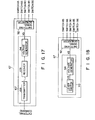
- Fig. 11 is a block diagram including an electronic circuit and its peripheral circuit, according to another embodiment of the present invention, and capable of being adapted to the transporting system of the present invention;
- Fig. 12 is a circuit diagram of a filter circuit shown in Fig. 11;
- Fig. 13 is a block diagram of a magnetic floating system, in which the circuit shown in Fig. 11 is applied to the transporting system shown in Fig. 7;
- Figs. 14A and 14B are block diagrams including an electronic circuit and its peripheral circuit; respectively, according to still another embodiment of the present invention, and capable of being adapted to the transporting system of the present invention;
- Fig. 15 is a block diagram of a control system of a circuit shown in Fig. 14;
- Fig. 16 is a circuit diagram of a feed-back gain compensator shown in Fig. 14; and
- Figs. 17 and 18 are circuit block diagrams of other examples of an actuator.
- In Figs. 1 to 3,
reference numeral 11 denotes a guide frame having an inverted U-shaped cross section and so disposed as to avoid obstacles in an office space and the like. Twoguide rails frame 11, andemergency rails frame 11. Open sides ofrails Carrier 15 is disposed belowrails rails stator 16 of a linear induction motor is disposed on the lower surface of the upper wall offrame 11 and betweenrails rails - Each of
rails like member 21 made of a ferromagnetic material in white so as to improve reflection of a light beam fromgap sensor 34, and has a split structure for facilitating installation in an office. Joint portion A ofmember 21 is subjected to predetermined joint processing. An arrangement ofcarrier 15 will now be described below. That is, plate-like base 25 is disposed to oppose the lower surfaces ofrails Base 25 is constituted bysplit plates 26a and 26b disposed along the running direction, and connectingmechanism 27 for connectingplates 26a and 26b so thatplates 26a and 26b can swing in a plane perpendicular to the running direction, i.e., about the running direction. Magneticfloating units 31 are disposed at the four corners of the upper surface ofbase 25, respectively. Eachunit 31 is mounted on the upper surface ofbase 25 bybolt 32 andseat 33.Optical gap sensor 34 is mounted onunit 31 to detect a gap length betweenunit 31 and the lower surfaces ofrails vessels plates 26a and 26b through connectingmembers vessels control units 41 for controlling fourunits 31, two regulators or constant-voltage generators 42, and two small-capacity power sources 43 for supplying electric power tounits 41 andgenerators 42. In addition, fourvertical wheels 45a and fourhorizontal wheels 45b are disposed at the four corners of the lower surface ofbase 25, respectively. Whenunits 31 lose their magnetic forces,wheels 45a contact the inner surface of upper and lower walls ofguides carrier 15 vertically, andwheels 45b contact the inner surfaces of the side walls ofguides carrier 15 in the lateral direction. Furthermore, first toseventh phototransistors 46 are disposed at predetermined positions on the upper surface ofbase 25 to transmit a command from the guide rails to a control system mounted oncarrier 15.Phototransistors 46 are so disposed as to oppose 7 LEDs (Light-Emitting Diodes) 47 mounted on the guide frame at a station in a predetermined position. Note thatbase 25 also serves as a reaction plate as an operation element of the above-mentioned linear induction motor. When the system is in operation,base 25 is so disposed as to opposestator 16 through a slight gap and supplied with a propulsive force therefrom. - Each
unit 31 is constituted by twoelectromagnets permanent magnet 53, as shown in Fig. 4. Electromagnets 51 and 52 are disposed along a direction perpendicular to the running direction ofcarrier 15 so as to oppose the lower end portions ofrails Permanent magnet 53 is interposed between the lower side surfaces ofelectromagnets electromagnets yoke 55 made of a ferromagnetic material, andcoil 56 wound aroundyoke 55.Coils 56 ofelectromagnets electromagnets - Prior to explanation of
units 41, a basic concept of this control system will be described below. - First, a magnetic circuit constituted by
unit 31, and its peripheral elements, i.e., rails 12a and 12b, gaps P, yokes 55, andmagnet 53 will be described. Note that for the sake of simplicity, a leakage magnetic flux of this magnetic circuit will be neglected. Magnetic reluctance Rm of the magnetic circuit is represented by the followina eauation (1):
- Assuming that the intensity of a magnetic field generated in gaps P when an exciting current does not flow through
coils 56 is Hm, that the length ofmagnet 53 is ℓm, that the total number of turns ofcoils 56 is N, and that the exciting current supplied to coils 56 is 1, total magnetic flux ϕ generated in the magnetic circuit is:
rails 

- On the other hand, interlinked magnetic flux number ϕN of
coils 56 connected in series with each other is:
- Therefore, a voltage equation of
coils 56 is obtained as follows assuming that a total resistance ofcoils 56 is R: - dϕN/dt = E - RI
- (∂ϕN/∂l)(dl/dt) + (∂ϕN/αz)(dz/dt) = E - RI
- (N2/Rm)(dl/dt) - (2N/µoSRm2)(Nl + Hmℓm)(dz/dt) = E - RI
- Therefore,

- As is apparent from equation (1), Rm is a function of gap length z. Therefore, assuming that the gap length is zo and the total magnetic reluctance is Rmowhen attractive force F and gravity mg are balanced with each other for I = O, equations (4) and (6) are linearized around gap length z = zo, speed dz/dt = O, and current I = O. In this case, z, dz/dt, and I are respectively represented as follows assuming that their micro amounts are Az, Δz, and Δi, respectively:
- z = zo + Az
- d /dt = O + Δz
- l = O + Δi
- Therefore, attractive force F of equation (4) is linearized around steady point (z,dz/dt,l) = (zoO,O) to obtain the following equation:
- F = (F)(z ,o,o) + (∂F/∂z))z o.o)Δz + (∂F/∂l) z o.o)Δi
- = - µoSHm2 m2/(2zo + ℓ/µs)2 + {4µoSHm2ℓm2/(2zo+ ℓ/µs)3}Δz -{2µoSHmℓmN(2zo + ℓ/µs)2}Δi Substitution of
- Fo = µoSHm2ℓm2/(2zo + ℓ/µs)2 = mg
- into the above equation yields the following eqution:
- F = -mg + (4mg/Rmo)Az - (2Nmg/Hmℓm)Δi
- As a result. eauation (4) can be summerized as follows:

- Similarly, equation (6) is linearized around steady point (z,dz/dt,l) = (zo,0,0) to obtain following equation (8):


- For the sake of simplicity, equation (9) is represented by following equation (10):

- A linear system represented by equation (9) is generally an unstable system. However, when applied voltage E is determined by various methods in accordance with state vector [Δz,Δż ,Ai] and acceleration Δ̇ż of equation (9) and a feed-back control is performed to the system, the system can be stabilized. For example, assuming that C is an output matrix (in this case, a unit matrix), and that X' = X - ΔXo andΔXo = [ΔZo,O,O], voltage E is represented by following equation (11):

- Assuming that Fi, F2, and F3 are feed-back constants;
- ΔZo, deviation (AZo = ZD - Zo) between target value ZDand gap length Zo of the gap length; and eo, an added voltage, equation (10) vields following equation (12):


- Δ3(s) = s3 + (b31F3 - a33)s2 + -{a21 + a23(b31F2 - a32)}s + a23b31F1 - a21(b31F3 - a33)
- A characteristic equation of ϕ(s) can be obtained by Δ3(s) = O. Therefore, by determining the values of F1, F2, and Fs, the characteristic root of ϕ(s) is arbitrarily located on a left half of a complex plane to achieve stabilization of the magnetic floating system. Fig. 5 is a block diagram of the magnetic floating system when such feed-back control for the magnetic floating unit is performed. That is, feed-back gain compensator C2 is added to object C1 to be controlled. Note that in Fig. 5, y represents CX.
- In such a magnetic floating system, as is apparent from equations (15) to (17), a steady deviation is generated in gap length deviation Δz and current deviation Δi during a stable state of the system along with changes in step-like external force Um, and target value ZD and added voltage eo of the gap length change. Therefore, by gradually varying value ZD and voltage eo of the gap length, the value of steady deviation of the gap length can be varied and finally
carrier 15 can be fixed on upper or lower portions of the inner walls ofguides - In a system according to the present invention,
units 31 are subjected to the feed-back control so as to set the steady deviation of current to be zero regardless of the presence/absence of step-like external force Um. In order to realize the above described feed-back control, the following control methods had been proposed in U.S. Serial No. 726, 975, filed April, 25, 1985: - ① A method in which force Um is observed by a state observer, and observed value Um is multiplied with a proper gain and then fed back to the magnetic floating system.
- ② A method in which gap length deviation Δz, speed deviation Δz̈., and current deviation Ai are all multiplied with proper gains which are not zero at the same time, and then the respective values are fed back to the magnetic floating system through a filter constituting a primary system of s.
- ③ A method in which current deviation Δi is integrated by an integrating compensator, and an output value therefrom is multiplied with a proper gain and then fed back to the magnetic floating system.
- These means for realizing feed-back are called a zero power feed-back loop.
- Method ③ is used in an example described hereinafter to explain a method of varying the steady deviation of the gap length and a method of finally fixing the carrier.
- Fig. 6 is a block diagram of the magnetic floating system adopting method ③. That is, according to the above method, the system includes, in addition to compensator C2, integrating compensator C3, target value generators C4 and C5, and a means for arbitrarily disabling compensator C3. Gain K of compensator C3 and target value r of generator C4 are represented by K = [O,O,K3] and r = [O,O,r3]T, respectively, where Ks is an integrating gain of current deviation Δi and r3 is an exciting current target value. Therefore, applied voltage E of this magnetic floating system is represented by the following equation (18):


- Assuming that Um, ΔZo, e, and r3 are inputs and y represented by y = CX is an output, transfer functions G(s), H(s), P(s), and Q(s) are respectiveiy represented as follows:


- Δ4(s) = S4 + (b31F3-a33)s3 + {b31K3-a21 + a23(b31F2-a32)}s2 + {a23b31F1 -a21(b31F3- a33)}s - a21b31K3 ...(24)
- Characteristic roots of functions G(s), H(s), P(s), and Q(s) can be obtained when A4(s) given by equation (24) is O, and the magnetic floating system of Fig. 6 can be stabilized by determining Fi, F2, F3, and F4.
- Assuming that the magnetic floating system of Fig. 6 is stable and Zo, eo, and r3 are simultaneously zero, a response of current deviation Δi with respect to external force Um can be obtained as follows using Laplace transform:

- Since force Um is a step-like external force in equation (25), Um(s) = Fo/s assuming that Fo is the magnitude of the external force. Therefore, equation (25) yields following equation (26):


- Note that examples of methods of obtaining elements of state vector X are as follows:
- (D A method in which all the elements are measured directly by a proper sensor.
- @ A method in which a proper one of output signals from a gap sensor, a speed sensor, an acceleration sensor, and the like is integrated or differentiated as needed by an integrator or a differentiator, thereby detecting Az, Az, and the like.
- (3) A method in which two elements of the state vector are detected by method (D or@ , and the remaining element is observed as needed together with external force Um by a state observer.
- In this embodiment, control is performed such that exciting current target value r3 is gradually varied from zero to a predetermined value only when the floating carrier is to be fixed on the guide rails. In this case, soft landing of the carrier can be realized without abruptly stopping zero power feed-back.
- On the other hand, the above method is not used when the carrier fixed on the guide rails is to be softly floated. This is because when
carrier 15 is attracted and fixed onrails rails control unit 41 is operated as if a counter force with respect tocarrier 15 fromrails rails carrier 15, thereby disabling start of floating ofcarrier 15. In this case, an operation of the zero power feed-back loop is stopped, andcarrier 15 is gradually floated by gradually varying gap length target value ZD or added voltage eo from a predetermined value to another value as described above. Immediately after that, the operation of the zero power feed-back loop may be started. - In accordance with the above description, an electrical arrangement of the
system including units 41 has an arrangement shown in Fig. 7.Unit 41 is constituted bysensor section 61 for detecting a magnetomotive force and magnetic reluctance generated in the magnetic circuit byunits 31, and changes in motion ofcarrier 15,operation circuit 62 for calculating electric power to be supplies tocoils 56 in accordance with a signal fromsection 61, andpower amplifier 63 for supplying electric power to coils 56 in accordance with a signal fromcircuit 62. Electric power fromsource 43 is supplied toamplifier 63 throughmain switch 64 andswitch 65. Electric power fromsource 43 is also supplied tocircuit 62 andsection 61 throughswitch 64,generator 42, andswitch 66.Generator 42 is constituted byreference voltage generator 42a andcurrent amplifier 42b, and outputs a constant voltage. The constant voltage fromgenerator 42 is also supplied toactuator 67. Outputs fromactuator 67 are supplied as command signals to switched 65 and 66, andcircuit 62. -
Sensor section 61 is constituted by modulatingcircuit 68 for modulating a signal fromsensor 34 so as to suppress an effect of external noise, andcurrent detector 69 for detecting a current value ofcoils 56. -
Operation circuit 62 realizes the feed-back magmetic floating system in Fig. 6. First, gap length set value ZD fromgenerator 70 is subtracted from a gap length detected bysensor 34 bysubtracter 71. Outputs fromsubtracter 71 are supplied to feed-back gain compensators differentiator 72, respectively. In addition, a current detection signal fromdetector 69 is supplied to fed-back gain compensator 75. Compensated outputs fromcompensators 73 to 75 are added byadder 76 and the sum is then supplied to one input terminal ofsubtracter 77. The current detection signal is compared with a current target value ("0" in a floating control state) fromtarget value generator 79 insubtracter 78. A comparison result is supplied to integratingcompensator 81 throughswitch unit 80, integration-compensated therein, and then supplied to the other input terminal ofsubtracter 77. Then, the output fromsubtracter 77 is used for gain adjustment ofamplifier 63. Therefore, zero power feed-back loop L consisting ofsubtracter 78,compensator 81 andsubtracter 77 is constituted. - Note that
switch unit 80 serves to selectively stop function ofcompensator 81 in accordance with a command fromactuator 67. As shown in Fig. 8,unit 80 may be arranged such that capacitor C, connected between the input and output terminals ofoperation amplifier 82 constitutingcompensator 81, is short-circuited in accordance with an output fromactuator 67. With this arrangement, gain K3 = -1/RC ofcompensator 81 becomes 0 in accordance with the output fromactuator 67, and the output fromamplifier 82 also becomes 0. - In addition,
generators actuator 67.Generators generator 70 is constituted such thatswitch 86 is provided between the input and output terminals of a filter constituting a primary delay system consisting ofamplifier 84, resistor Rb, and capacitor Cb.Generator 79 is similarly constituted such thatswitch 85 is provided between the input and output terminals of a filter constituting a primary delay system consisting ofamplifier 83, resistor Ra, and capacitor Ca.Switches actuator 67.Generators 
generators -
Actuator 67 is constituted byexternal command converter 91 and switchingsignal generator 92, as shown in Fig. 10.Converter 91 is constituted by energizingcircuit 93 for supplying an exciting current to the sevenLEDs 47 in a guide rail side to driveLEDs 47 mounted onframe 11 in accordance with the external command,LEDs 47 mounted onframe 11, sevenphototransistors 46 connected to constant-voltage generator 42 and mounted in positions corresponding toLEDs 47 ofcarrier 15 at a station, andvoltage generator 94 for outputting a binary-value voltage in accordance with outputs from central fivephototransistors 46. In addition,generator 92 connected to constant-voltage generator 42 converts a 5-bit output fromconverter 91 into switching signals for opening/closing switched 65, 66, 80, 85, and 86, and supplies them to the corresponding switches, thereby controlling open/closed states of the switches. Note that the output from the remaining twophototransistors 46 arranged at both sides serve to detect whetherLEDs 47 andphototransistors 46 properly oppose each other. Only when these twophototransistors 46 receive light beams fromLEDs 47 at the same time, the external command is transmitted from the guide rails to the carrier. For this reason, erroneous transmission of the external command caused when the carrier does not stop at a correct position can be prevented. - An operation of the transporting system of floated carrier type according to the embodiment of the present invention will be described below.
- In this embodiment, when the system is not operated,
vertical wheels 45a ofcarrier 15 are brought into contact with the inner wall upper surfaces ofrails magnet 53, switches 65 and 66 are opened, and switches 80, 85, and 86 are closed. - In this state, when
switch 64 is turned on,actuator 67 located at carrier side is actuated bygenerator 42, and a command is output so as to closeswitch 66,unit 41 starts operation. - When a command is output so as to close
switch 65 and to openswitch 86, control is performed such that target value Zo of the gap length is gradually increased in a state wherein an operation of zero power feed-back loop L is stopped, i.e., in the floating system shown in Fig. 5. As a result,unit 41 causeselectromagnets magnet 53, and controls a current to be flowed throughcoils 56 so as to generate a predetermined gap betweenunits 31 andrails magnet 53,yoke 55, gap P, rails 12a and 12b, gap P,yoke 55, andmagnet 53, so thatcarrier 15 softly starts floating. At this time, if the external command is output so as to openswitch 80, loop L starts operation, and the magnetic circuit maintains predetermined gap length zo so thatcarrier 15 obtaines a magnetic attractive force not requiring the magnetic flux generated byelectromagnets carrier 15. - When external force Um is applied in this state,
sensor 34 detects this and transmits a detection signal tocircuit 62 throughcircuit 68.Circuit 62 subtracts gap length target value xD from the detection signal bysubtracter 71, thereby calculating gap length deviation signal Az-Azo. Signal Az-Azo is input tocompensator 73, and converted into speed deviation signal Az bydifferentiator 72, which is input tocompensator 74. On the other hand, current deviation signal Ai is obtained by a measurement signal ofdetector 69, and input tocompensator 75. Signal Ai is compared with a zero level as an output fromgenerator 79 bysubtracter 78, and its difference signal is input tocompensator 81. Output signals from threecompensators 73 to 75 added with each other byadder 76 and the signal fromcompensator 81 are respectively multiplied with predetermined gains and fed back toamplifier 63. Thus, the system is stabilized in a state wherein signal Ai becomes zero. - Assuming that
carrier 15 is placed immediately belowstator 16 of the linear induction motor andstator 16 is energized,base 25 is subjected to an electromagnetic force fromstator 16, andcarrier 15 starts running alongrails stator 16 is arranged before a position at whichcarrier 15 is completely stopped by an effect of air resistance and the like,carrier 15 is energized again to continuously move alongrails carrier 15 can be moved to a destination in a noncontacting state. - When the external command for opening
switch 85 is supplied to actuator 67 ofcarrier 15 which has arrived at the destination, i.e., a station, the output fromgenerator 79 gradually varies from the zero level to the predetermined value, and gap length Z is gradually decreased.Wheels 45a ofcarrier 15 are finally brought into contact with the inner wall upper surfaces ofrails switch 65 andclose switches electromagnets carrier 15 is attracted and fixed onrails magnet 53, and the operation of loop L and internal states ofgenerators carrier 15 toward another destination, a command may be output to closeswitch 65 andopen switch 86, thereby repeating the above-mentioned procedure. - On the other hand, when
carrier 15 is to be attracted and fixed at the destination for a long period of time, an external command may be output to openswitch 66, thereby saving the electric power consumed byunit 41. In addition, whenswitch 64 is opened after that, the operation of the system can be completely stopped. - Note that the present invention is not limited to the above embodiment. For example, in the above embodiment,
actuator 67 andgenerators - For example, Fig. 11 shows an embodiment in which compensator 81 of Fig. 7 is replaced with
filter 95 having a primary transfer function. Assuming that a time constant of fitter 95 is Tf, its transfer function is defined as follows:
detector 69 is supplied as an input tosubtracter 78. However, in this embodiment, the output fromsubtracter 71 is supplied.Filter 95 is constituted such that capacitor Cc and resistor Re are connected in parallel with each other between the input and output terminals ofoperation amplifier 96, as shown in Fig. 12. Also in this case, when both ends of capacitor Cc and resistor Re are short-circuited byswitch 80, zero power feed-back loop L is deenergized. - According to this method, in an existing magnetic floating system adopting a control method shown in Fig. 5, loop L can be added while maintaining a sufficiently stable magnetic floating state by setting a large value of Tf without calculating feed-back gain F = [F1,F2,F3] again. Assuming that P = [-F1,O,O] and r = [r1,O,O]T, its block diagram is shown in Fig. 13.
- Figs. 14A and 14B show a control method using
state observer 101. In Fig. 14A,observer 101 receives output signals fromsubtracter 71 anddetector 69, detects speed Az corresponding to the output signal fromdifferentiator 72 in the above-mentioned embodiment and a steady component of external force Um acting oncarrier 15, and outputs a gap length deviation signal, a speed signal, a current deviation signal, and an external steady component signal to compensators 73, 74, 75, and 102. Fourcompensators 73 to 75 and 102 multiply the inputs by gains Fi, F2, Fs, and F4, respectively, and output the products. After these outputs are added byadder 103, the sum is compared with a O signal as an output fromgenerator 79 and is then output toamplifier 63. Note that F4 = +(d21/a21)F1. Fig. 15 is a block diagram of this control system, in whichobserver 101 is denoted by C7. In Fig. 15, respective symbols are represented by the following equations:


- On the other hand, peripheral elements of
compensator 102 are arranged such that, as shown in Fig. 16, ON/OFF control ofcontactless relay 105 is performed in accordance with a signal fromactuator 67 so as to short-circuit resistor Rd connected between the input and output terminals ofoperation amplifier 106, and whenactuator 67 outputs a signal for turning onrelay 105, loop L is deenergized. - In Fig. 14B, a
subtractor 181 is connected betweenswitch 80 andstate observer 101, atarget value generator 79 is connected betweensubtractor 181 andactuator 67 and atarget value generator 180 for generating a zero target value is connected tosubtractor 180. The circuit shown in Fig. 14B is operated in a similar manner as that of Fig. 14A and also has an advantage same as that of Fig. 14B. According to this embodiment, since speed Δ can be observed without using a differentiator, an adverse effect of an external electricalnoise froating carrier 15 is reduced. - In addition,
actuator 67 of the present invention is not limited to the arrangement shown in Fig. 10 but may have arrangements as shown in Figs. 17 and 18. That is, in the arrangement shown in Fig. 17,external command converter 107 is constituted bytransmitter 108 andreceiver 109 for transmitting/receiving radio waves, andvoltage generator 94. As compared with the above-mentioned case wherein optical signals are transmitted/received, mounting positions of transmitting and receiving sections need not be so strictly adjusted. - Furthermore, in the arrangement shown in Fig. 18,
external command converter 110 is constituted by fivelever switches 111 mounted oncarrier 15, andgenerator 94 interlocked with ON/OFF operations ofswitches 111 to output open/close signals of the switches, resulting in a simple arrangement of the system. Thus, the present invention can be modified within the spirit and scope of the invention regardless of analog or digital arrangement as long as the control system includes a zero power feed-back control system. As has been described above, according to the present invention, since the zero power feed-back loop is deenergized and the target value is gradually varied in the soft landing or starting mode, the steady deviation of the gap length can be gradually varied. For this reason, the carrier can be softly fixed on the guide rails or softly started to flow from the guide rails, thereby preventing destruction of the carrier or cargo, or generation of dust.
Claims (10)
Applications Claiming Priority (2)
| Application Number | Priority Date | Filing Date | Title |
|---|---|---|---|
| JP61109915A JP2732562B2 (en) | 1986-05-14 | 1986-05-14 | Floating transfer device |
| JP109915/86 | 1986-05-14 |
Publications (3)
| Publication Number | Publication Date |
|---|---|
| EP0246098A2 true EP0246098A2 (en) | 1987-11-19 |
| EP0246098A3 EP0246098A3 (en) | 1989-10-04 |
| EP0246098B1 EP0246098B1 (en) | 1991-11-13 |
Family
ID=14522365
Family Applications (1)
| Application Number | Title | Priority Date | Filing Date |
|---|---|---|---|
| EP87304290A Expired - Lifetime EP0246098B1 (en) | 1986-05-14 | 1987-05-14 | Transporting system of floated carrier type |
Country Status (5)
| Country | Link |
|---|---|
| US (1) | US4838172A (en) |
| EP (1) | EP0246098B1 (en) |
| JP (1) | JP2732562B2 (en) |
| KR (1) | KR910003999B1 (en) |
| DE (1) | DE3774486D1 (en) |
Cited By (8)
| Publication number | Priority date | Publication date | Assignee | Title |
|---|---|---|---|---|
| EP0335719A2 (en) * | 1988-03-30 | 1989-10-04 | Kabushiki Kaisha Toshiba | Attraction type magnetic levitating apparatus |
| US4882999A (en) * | 1986-12-19 | 1989-11-28 | Kabushiki Kaisha Toshiba | Transportation system of a floated-carrier type |
| US5156093A (en) * | 1986-12-19 | 1992-10-20 | Kabushiki Kaisha Toshiba | Transportation system of floated-carrier type |
| EP0580107A1 (en) * | 1992-07-20 | 1994-01-26 | Daifuku Co., Ltd. | Magnetic levitation transport system |
| EP0584790A1 (en) * | 1992-08-26 | 1994-03-02 | Ebara Corporation | Zero-power control type vibration eliminating apparatus |
| DE102004037622A1 (en) * | 2004-08-02 | 2006-02-23 | Leybold Optics Gmbh | Process system and device for transporting substrates |
| EP2746201A1 (en) * | 2012-12-21 | 2014-06-25 | Robert Bosch Gmbh | Apparatus and method for conveying carriers in a machine |
| WO2015162182A1 (en) * | 2014-04-25 | 2015-10-29 | Weber Maschinenbau Gmbh Breidenbach | Autonomously electromagnetic transport carrier of food portions |
Families Citing this family (16)
| Publication number | Priority date | Publication date | Assignee | Title |
|---|---|---|---|---|
| JPH0817524B2 (en) * | 1987-11-06 | 1996-02-21 | 住友電気工業株式会社 | Magnetic levitation carrier |
| US4924778A (en) * | 1988-03-30 | 1990-05-15 | Kabushiki Kaisha Toshiba | Attraction type magnetic levitating apparatus |
| JPH02294203A (en) * | 1989-05-09 | 1990-12-05 | Yaskawa Electric Mfg Co Ltd | Magnetic levitation control method |
| JP4270657B2 (en) | 1999-07-06 | 2009-06-03 | 東芝エレベータ株式会社 | Elevator guide device |
| JP4097848B2 (en) | 1999-07-06 | 2008-06-11 | 東芝エレベータ株式会社 | Elevator guide device |
| WO2005007549A1 (en) * | 2003-06-20 | 2005-01-27 | Otis Elevator Company | Elevator active suspension utilizing repulsive magnetic force |
| JP4986400B2 (en) * | 2005-01-05 | 2012-07-25 | 東芝エレベータ株式会社 | elevator |
| JP4614091B2 (en) * | 2005-08-16 | 2011-01-19 | 株式会社ダイフク | Floating unit and article support device |
| JP5099629B2 (en) * | 2007-10-23 | 2012-12-19 | 東芝エレベータ株式会社 | Magnetic levitation device |
| JP2012514162A (en) * | 2009-01-21 | 2012-06-21 | 福州市規劃設計研究院 | Magnetic levitation type vibration-proof structure |
| DE102009038756A1 (en) | 2009-05-28 | 2010-12-09 | Semilev Gmbh | Device for particle-free handling of substrates |
| CN110304092B (en) * | 2018-03-27 | 2020-08-04 | 中车唐山机车车辆有限公司 | Magnetic suspension bogie and train |
| DE102018118814A1 (en) | 2018-08-02 | 2020-02-06 | Beckhoff Automation Gmbh | Method for identifying a carriage of a linear transport system |
| CN109094422B (en) * | 2018-08-06 | 2020-04-07 | 江西理工大学 | Suspension type track traffic equipment and magnetoelectric hybrid suspension rail system therein |
| CN109292464A (en) * | 2018-10-24 | 2019-02-01 | 西南交通大学 | A kind of electrodynamics suspension pipeline goods transport systems |
| CN112848914B (en) * | 2021-03-27 | 2022-09-16 | 湖南凌翔磁浮科技有限责任公司 | High-speed magnetic suspension controller and control system |
Citations (3)
| Publication number | Priority date | Publication date | Assignee | Title |
|---|---|---|---|---|
| US3638093A (en) * | 1971-04-19 | 1972-01-25 | Rohr Corp | Magnetic suspension and propulsion system |
| JPS60170401A (en) * | 1984-02-14 | 1985-09-03 | Toshiba Corp | Levitating type conveying apparatus |
| EP0179188A2 (en) * | 1984-10-23 | 1986-04-30 | Kabushiki Kaisha Toshiba | Transporting system of floated carrier type |
Family Cites Families (8)
| Publication number | Priority date | Publication date | Assignee | Title |
|---|---|---|---|---|
| US3377616A (en) * | 1964-04-27 | 1968-04-09 | Gen Signal Corp | Vehicle identification system |
| US3736880A (en) * | 1971-04-19 | 1973-06-05 | Rohr Industries Inc | Feedback control circuit for magnetic suspension and propulsion system |
| US3937148A (en) * | 1973-01-02 | 1976-02-10 | Cambridge Thermionic Corporation | Virtually zero power linear magnetic bearing |
| US3899979A (en) * | 1973-02-22 | 1975-08-19 | Buryan Associates | Magnetic suspension systems for vehicles |
| JPS51100515A (en) * | 1975-02-28 | 1976-09-04 | Tokyo Shibaura Electric Co | JODENDOJIKI FUJOSHA |
| JPS5288913A (en) * | 1976-01-21 | 1977-07-26 | Hitachi Ltd | Float-up height control system |
| DE3117971C2 (en) * | 1981-05-07 | 1984-06-07 | Messerschmitt-Bölkow-Blohm GmbH, 8012 Ottobrunn | Control for optimal performance adjustment of the air gap of electromagnetic levitation vehicles |
| JPH0624405B2 (en) * | 1985-07-03 | 1994-03-30 | 株式会社東芝 | Floating carrier |
-
1986
- 1986-05-14 JP JP61109915A patent/JP2732562B2/en not_active Expired - Lifetime
-
1987
- 1987-05-13 US US07/049,346 patent/US4838172A/en not_active Expired - Fee Related
- 1987-05-14 EP EP87304290A patent/EP0246098B1/en not_active Expired - Lifetime
- 1987-05-14 KR KR1019870004753A patent/KR910003999B1/en not_active IP Right Cessation
- 1987-05-14 DE DE8787304290T patent/DE3774486D1/en not_active Expired - Lifetime
Patent Citations (3)
| Publication number | Priority date | Publication date | Assignee | Title |
|---|---|---|---|---|
| US3638093A (en) * | 1971-04-19 | 1972-01-25 | Rohr Corp | Magnetic suspension and propulsion system |
| JPS60170401A (en) * | 1984-02-14 | 1985-09-03 | Toshiba Corp | Levitating type conveying apparatus |
| EP0179188A2 (en) * | 1984-10-23 | 1986-04-30 | Kabushiki Kaisha Toshiba | Transporting system of floated carrier type |
Non-Patent Citations (1)
| Title |
|---|
| PATENT ABSTRACTS OF JAPAN vol. 10, no. 6 (M-445)(2063) 11 January 1986, & JP-A-60 170401 (TOSHIBA) 03 September 1985, * |
Cited By (15)
| Publication number | Priority date | Publication date | Assignee | Title |
|---|---|---|---|---|
| US4882999A (en) * | 1986-12-19 | 1989-11-28 | Kabushiki Kaisha Toshiba | Transportation system of a floated-carrier type |
| US4934279A (en) * | 1986-12-19 | 1990-06-19 | Kabushiki Kaisha Toshiba | Transportation system of a floated-carrier type |
| US5156093A (en) * | 1986-12-19 | 1992-10-20 | Kabushiki Kaisha Toshiba | Transportation system of floated-carrier type |
| EP0335719A3 (en) * | 1988-03-30 | 1991-06-12 | Kabushiki Kaisha Toshiba | Attraction type magnetic levitating apparatus |
| EP0335719A2 (en) * | 1988-03-30 | 1989-10-04 | Kabushiki Kaisha Toshiba | Attraction type magnetic levitating apparatus |
| US5467718A (en) * | 1992-07-20 | 1995-11-21 | Daifuku Co., Ltd. | Magnetic levitation transport system with non-contact inductive power supply and battery charging |
| EP0580107A1 (en) * | 1992-07-20 | 1994-01-26 | Daifuku Co., Ltd. | Magnetic levitation transport system |
| EP0584790A1 (en) * | 1992-08-26 | 1994-03-02 | Ebara Corporation | Zero-power control type vibration eliminating apparatus |
| US5449985A (en) * | 1992-08-26 | 1995-09-12 | Ebara Corporation | Zero-power control type vibration eliminating apparatus |
| DE102004037622A1 (en) * | 2004-08-02 | 2006-02-23 | Leybold Optics Gmbh | Process system and device for transporting substrates |
| EP2746201A1 (en) * | 2012-12-21 | 2014-06-25 | Robert Bosch Gmbh | Apparatus and method for conveying carriers in a machine |
| WO2015162182A1 (en) * | 2014-04-25 | 2015-10-29 | Weber Maschinenbau Gmbh Breidenbach | Autonomously electromagnetic transport carrier of food portions |
| CN106455591A (en) * | 2014-04-25 | 2017-02-22 | 韦伯机械制造有限公司布雷登巴赫 | Autonomously electromagnetic transport carrier of food portions |
| CN106455591B (en) * | 2014-04-25 | 2020-06-19 | 韦伯机械制造有限公司布雷登巴赫 | Automatic electromagnetic transport carrier for food parts |
| US10737403B2 (en) | 2014-04-25 | 2020-08-11 | Weber Maschinenbau Gmbh Breidenbach | Autonomously electromagnetic transport carrier of food portions |
Also Published As
| Publication number | Publication date |
|---|---|
| DE3774486D1 (en) | 1991-12-19 |
| JP2732562B2 (en) | 1998-03-30 |
| JPS62268306A (en) | 1987-11-20 |
| KR870011738A (en) | 1987-12-26 |
| KR910003999B1 (en) | 1991-06-20 |
| EP0246098B1 (en) | 1991-11-13 |
| US4838172A (en) | 1989-06-13 |
| EP0246098A3 (en) | 1989-10-04 |
Similar Documents
| Publication | Publication Date | Title |
|---|---|---|
| EP0246098A2 (en) | Transporting system of floated carrier type | |
| US4825773A (en) | Transporting system of floated-carrier type | |
| EP0169983B1 (en) | Transporting system of floated carrier type | |
| EP0179188A2 (en) | Transporting system of floated carrier type | |
| US4882999A (en) | Transportation system of a floated-carrier type | |
| EP0246096B1 (en) | Transportation system of a floated-carrier type | |
| US4732087A (en) | Transportation system of a floated-carrier type | |
| US5058505A (en) | Carrying apparatus driven by linear motor with weight calculation to control driving force of motor | |
| JP2793240B2 (en) | Floating transfer device | |
| KR900006247B1 (en) | Transportation system of a floated-carrier type | |
| EP0487744B1 (en) | Underwater linear transport system | |
| JPH01152905A (en) | Magnetic levitation carrier | |
| EP0239231B1 (en) | Apparatus for stopping carriage at preselected position | |
| JPS61224808A (en) | Levitating conveyor | |
| JPH0345106A (en) | Magnetic levitation carrier | |
| JPH0669244B2 (en) | Magnetic levitation transfer system | |
| EP3915823A1 (en) | System for transmitting electric energy to a vehicle over the air | |
| JPS63274309A (en) | Magnetic levitation conveyor | |
| JPH06171754A (en) | Transport device | |
| JPH03159503A (en) | Magnetic levitation carrier | |
| JPS62281703A (en) | Carrier device | |
| JP2778882B2 (en) | Floating transfer device | |
| JP2760495B2 (en) | Floating transfer device | |
| JPH0847112A (en) | Levitation type conveyor | |
| JPS62126413A (en) | Positioning device for moving body in carrying device |
Legal Events
| Date | Code | Title | Description |
|---|---|---|---|
| PUAI | Public reference made under article 153(3) epc to a published international application that has entered the european phase |
Free format text: ORIGINAL CODE: 0009012 |
|
| AK | Designated contracting states |
Kind code of ref document: A2 Designated state(s): DE FR GB |
|
| 17P | Request for examination filed |
Effective date: 19880204 |
|
| PUAL | Search report despatched |
Free format text: ORIGINAL CODE: 0009013 |
|
| AK | Designated contracting states |
Kind code of ref document: A3 Designated state(s): DE FR GB |
|
| 17Q | First examination report despatched |
Effective date: 19910226 |
|
| GRAA | (expected) grant |
Free format text: ORIGINAL CODE: 0009210 |
|
| AK | Designated contracting states |
Kind code of ref document: B1 Designated state(s): DE FR GB |
|
| REF | Corresponds to: |
Ref document number: 3774486 Country of ref document: DE Date of ref document: 19911219 |
|
| ET | Fr: translation filed | ||
| PLBE | No opposition filed within time limit |
Free format text: ORIGINAL CODE: 0009261 |
|
| STAA | Information on the status of an ep patent application or granted ep patent |
Free format text: STATUS: NO OPPOSITION FILED WITHIN TIME LIMIT |
|
| 26N | No opposition filed | ||
| PGFP | Annual fee paid to national office [announced via postgrant information from national office to epo] |
Ref country code: GB Payment date: 19980505 Year of fee payment: 12 |
|
| PGFP | Annual fee paid to national office [announced via postgrant information from national office to epo] |
Ref country code: FR Payment date: 19980511 Year of fee payment: 12 |
|
| PGFP | Annual fee paid to national office [announced via postgrant information from national office to epo] |
Ref country code: DE Payment date: 19980522 Year of fee payment: 12 |
|
| PG25 | Lapsed in a contracting state [announced via postgrant information from national office to epo] |
Ref country code: GB Free format text: LAPSE BECAUSE OF NON-PAYMENT OF DUE FEES Effective date: 19990514 |
|
| GBPC | Gb: european patent ceased through non-payment of renewal fee |
Effective date: 19990514 |
|
| PG25 | Lapsed in a contracting state [announced via postgrant information from national office to epo] |
Ref country code: FR Free format text: LAPSE BECAUSE OF NON-PAYMENT OF DUE FEES Effective date: 20000131 |
|
| PG25 | Lapsed in a contracting state [announced via postgrant information from national office to epo] |
Ref country code: DE Free format text: LAPSE BECAUSE OF NON-PAYMENT OF DUE FEES Effective date: 20000301 |
|
| REG | Reference to a national code |
Ref country code: FR Ref legal event code: ST |