EP0244001B1 - Hybrid coder for videosignals - Google Patents
Hybrid coder for videosignals Download PDFInfo
- Publication number
- EP0244001B1 EP0244001B1 EP87200651A EP87200651A EP0244001B1 EP 0244001 B1 EP0244001 B1 EP 0244001B1 EP 87200651 A EP87200651 A EP 87200651A EP 87200651 A EP87200651 A EP 87200651A EP 0244001 B1 EP0244001 B1 EP 0244001B1
- Authority
- EP
- European Patent Office
- Prior art keywords
- low
- data blocks
- pass
- processing unit
- unit
- Prior art date
- Legal status (The legal status is an assumption and is not a legal conclusion. Google has not performed a legal analysis and makes no representation as to the accuracy of the status listed.)
- Expired - Lifetime
Links
Images

Classifications
-
- H—ELECTRICITY
- H04—ELECTRIC COMMUNICATION TECHNIQUE
- H04N—PICTORIAL COMMUNICATION, e.g. TELEVISION
- H04N19/00—Methods or arrangements for coding, decoding, compressing or decompressing digital video signals
- H04N19/80—Details of filtering operations specially adapted for video compression, e.g. for pixel interpolation
- H04N19/82—Details of filtering operations specially adapted for video compression, e.g. for pixel interpolation involving filtering within a prediction loop
-
- H—ELECTRICITY
- H04—ELECTRIC COMMUNICATION TECHNIQUE
- H04N—PICTORIAL COMMUNICATION, e.g. TELEVISION
- H04N19/00—Methods or arrangements for coding, decoding, compressing or decompressing digital video signals
- H04N19/60—Methods or arrangements for coding, decoding, compressing or decompressing digital video signals using transform coding
- H04N19/61—Methods or arrangements for coding, decoding, compressing or decompressing digital video signals using transform coding in combination with predictive coding
Definitions
- a hybrid encoder with the specified features is described in a conference report (Draft version Document Sim 85/78 Report COST 211 to Simulation Subgroup Meeting, Swiss, December 10 to 11, 1985) of the COST group.
- a basic circuit diagram of the known hybrid encoder is shown in FIG. 1. The main purpose of the encoder shown is to recode the video data coming from a video data source with as little information loss as possible into a signal with the lowest possible bit rate.
- interframe principle in which the correlation between temporally successive video images (this term is used here for full and partial images) is used
- intra-frame principle in which the correlation of the video data within a video image is used.
- the data must be prepared before the actual coding process.
- This processing is adopted in the hybrid coder of FIG. 1 by a functional unit PP (p re p rocessing).
- the data is transferred to the encoder in blocks.
- Such a video data block contains the data of certain pixels of a video image, which are interpreted as elements of a square number matrix (for the meaning of the terms used here in connection with number matrices, see Wigner, EP: Group Theory; Academic Press New York and London 1959, page 1 to 30).
- a data block can consist of the chrominance values of the first eight pixels of the first eight lines of a video image.
- the functional unit PP divides each video image into data blocks of the same size.
- the decomposition rule also contains the assignment of an identifier to each data block.
- the data block just given as an example could be symbolized and identified by b 11, for example.
- Data blocks from successive video images that have the same identifier are referred to here as corresponding data blocks.
- a data block for example the data block b 11 to an input of a subtractor SR
- the corresponding data block - symbolized, for example, by b 11 - of the previous video image from an image memory BS is given to the other input of the subtractor SR.
- the subtractor SR forms the difference between the two blocks in the sense of the difference between two matrices (cf. Wigner lc, page 7); this difference block is now subjected to further operations.
- the transformation by the unit F corresponds approximately to the Fourier transformation (more precisely, it is a special two-dimensional Fourier transformation) in acoustic signal transmission: the block D 11 can usually be coded with fewer binary digits than the block d 11.
- the transformed signal then passes through a quantizer Q, which again ensures data reduction. So that the entire signal with constant bit rate on a buffer P can be provided.
- a multiplexer MUX interleaves the useful signal read out from the buffer memory P with control information which, in the present case, serves, among other things, to set a quantizer on the receiver side (these are adaptive quantizers).
- the signal is also looped back to the input of the hybrid encoder via a feedback path.
- the block D 11 modified by the quantizer Q is regenerated by a regeneration unit (not shown) to such an extent that it matches the original block D 11 except for rounding errors.
- the data block b 11 at the output of the adder AR (except for rounding errors) of the video image just supplied via the functional unit PP.
- This data block is read into it via an input E of the image memory BS and takes on the role of the data block b 11 there, which is now deleted.
- bit rate reduction depends crucially on the design of the quantizer Q. If the quantization intervals are large, the following applies this also applies to bit rate reduction, but the image quality is particularly annoying due to the high quantization errors. For example, a checkerboard-like pattern can arise on the screen, which results from the division of a video image into blocks, or there are constantly changing structures (artifacts) that can lead to the complete distortion of the reproduced image.
- adaptive quantizers i.e. quantizers whose characteristic is changed by the video signal.
- the effort is considerable, among other things, because additional information about the state of the quantizer has to be transmitted to the receiver.
- the data blocks coming from the functional unit PP and from the image memory BS are - as mentioned above - subjected to a special, areal Fourier transformation (cosine transformation). Empirical studies have shown that there is only a slight correlation between the coefficients belonging to high frequencies (better: wavenumbers) and corresponding data blocks. The high frequency components of the data blocks that come from the functional unit PP are therefore statistically independent of the high frequency components of the data blocks that come from the image memory BS.
- the invention is therefore based on the object of providing a hybrid encoder of the type mentioned at the outset, by means of which an improved image quality is achieved.
- Such a means can be a low-pass unit for performing a matrix operation with a low-pass character, which is directly connected to the output or input of the image memory.
- the low-pass unit attenuates the high frequency components of the data blocks that come from the image memory or the adder. This improves the image quality on the receiver side because unsuitable portions of the image are no longer used for coding on the transmitter side. Among other things, this leads to a smaller number of bits required for coding the differential blocks.
- a unit can also be arranged in front of or behind the operation unit for performing a cosine transformation and an operation unit between the image memory and adder.
- a second operation unit coupled to the first operation unit connected downstream of the subtractor and contained in the feedback path, for carrying out an inverse cosine transformation is arranged in front of the adder, that between the adder and the input of the image memory or immediately behind the Output of the image memory a low-pass unit is arranged and that a further low-pass unit for performing a matrix operation with low-pass character of the data blocks of the video image is arranged between the functional unit for dividing the data of a video image into data blocks of equal size and the subtractor.
- the further low-pass unit serves to limit the band of the data blocks coming from the functional unit.
- the low-pass effect of the low-pass unit, which lies between the functional unit and the subtractor, is less than the low-pass effect of the low-pass unit, which is arranged directly behind the output of the image memory.
- the band limitation of the data blocks coming from the functional unit reduces the annoying quantization noise at the expense of image sharpness (blurring). However, such blurring is less disturbing than the disturbances mentioned at the outset due to the quantization error.
- a second operation unit coupled to the first operation unit connected downstream of the subtractor and contained in the feedback path for performing an inverse cosine transformation is arranged in front of the adder, that a low-pass unit is arranged directly behind the first operation unit and that a fourth operation unit for receiving the data blocks from the image memory, for performing a matrix operation with a low-pass character of the data blocks supplied from the image memory and for supplying the filtered data blocks to the adder is arranged in front of the adder.
- the high frequency components of the data blocks from the image memory damped by the low-pass unit and the fourth operation unit are also limits the data blocks originating from the functional unit. This also reduces the annoying quantization noise at the expense of sharpness.
- a diagonal matrix can serve as a matrix for the low-pass unit, which is provided for carrying out a matrix operation with a low-pass character.
- a second operation unit coupled to the first operation unit connected downstream of the subtractor and contained in the feedback path for carrying out an inverse cosine transformation is arranged in front of the adder, and that a low-pass unit is arranged between the subtractor and the first operation unit and that a further operation unit for receiving the data blocks from the image memory, for performing a matrix operation with a low-pass character of the data blocks supplied from the image memory and for supplying the filtered data blocks to the adder is arranged in front of the adder.
- the high frequency components of the data blocks from the image memory are damped by the low-pass unit and the further operation unit.
- the low-pass unit also limits the data blocks originating from the functional unit. This also eliminates the annoying quantization noise at the expense of sharpness reduced.
- the mode of operation of the low-pass operation units is changed depending on the fill level of a buffer memory coupled to the output of the first operation unit, or depending on the displacement vector, or both.
- the first operation unit is arranged between the functional unit for dividing the data of a video signal into data blocks of the same size and the subtractor, that the low-pass unit is coupled to the output of the subtractor, and that another low-pressure unit is located in front of the adder is arranged to receive the data blocks from the image memory, to carry out a matrix operation with a low-pass character of the data blocks supplied by the image memory and to supply the filtered data blocks to the adder.
- the high frequency components of the data blocks from the image memory are damped by two low-pass units.
- the low-pass unit upstream of the adder also limits the data blocks originating from the functional unit. This also reduces the annoying quantization noise at the expense of sharpness. Since the first operation unit, which carries out the cosine transformation, is arranged between the functional unit and the subtractor, no further operation unit is required in the feedback path for an inverse cosine transformation.
- a hybrid decoder is also provided for decoding video signals encoded by a hybrid encoder.
- This contains one Operation unit which is provided for receiving data blocks of the same size of the video image, for carrying out an inverse cosine transformation and for the delivery of transformed data blocks, an adder which receives the transformed data blocks at an input, the output of which is coupled to its other input via an image memory, and an operating unit arranged between the output of the image memory and the other input of the adder for performing a matrix operation with a low-pass character of the data blocks supplied by the image memory.
- Fig. 2 differs from Fig. 1 only by two operation units, namely T and FTI.
- the designations for the remaining units are the same as in FIG. 1.
- the operation unit T lies between the operation unit F and the quantizer Q, while the operation unit FTI the output signal of the image memory BS deformed in the sense explained below and then passed on to an input of the adder AR.
- the subtractor SR is supplied via the functional unit PP while at the same time at the output A of the image memory BS the data block b 11 is present.
- the unit T which is assigned a matrix h , makes it the block h t a ⁇ 1d11ah , where h t means the matrix transposed to h (cf. Wigner lc, p. 23).
- a matrix operation with a low-pass character is carried out with the matrix h ; further details will be given below.
- the block specified last reaches the operational unit IF, which effects a transformation inverse to the transformation of the unit F; this means that the block ah t a ⁇ 1d11aha ⁇ 1 now appears at the output of the unit IF.
- the low-pass filtered blocks are read into the image memory BS, so an unsharp image is stored and also transmitted. This sharpness of formation is the price to be paid for the suppression of quantization errors.
- the quantizer Q can, for example, be a non-adaptive quantizer or can be omitted entirely if the bit rates are low enough.
- the operating unit F uses the matrix a to carry out a cosine transformation (cf., for example, Pratt, WK: Digital Image Processing; John Wiley & Sons 1978, pp. 242-247).
- the matrix a is therefore known to the person skilled in all details.
- a particularly simple matrix namely a diagonal matrix (cf. Wigner lc, p. 8), can be specified for h .
- Filter matrices that filter the blocks in the spatial area have the same structure as the following auxiliary matrix m : From the second line of the matrix m , three elements - here 1, 0, 1 - are shifted one place to the right with each additional line; all other elements of the line are zero. The first two elements of the first line and the last two elements of the last line consist of ones, while here, too, all other elements consist of zeros.
- the number of lines in the matrix m (it corresponds to the number of columns) is as large as the number of lines or number of columns in the blocks to be processed.
- the matrix w as the matrix with I as the unit matrix, for k less than 1 but greater than or equal to 0.5, a whole class of filter matrices with a low-pass character results.
- Each power of w also results in a matrix with a low-pass character.
- the low-pass filtering can be refined by changing the matrices h and w as a function of the signal, so that the filtering is carried out adaptively. Then additional information must be transmitted to the receiver for decoding. This transmission of the additional information is indicated, for example, by a connection of the unit T to the multiplexer MUX. The same connections also exist between the other units with a low-pass effect and the multiplexer MUX; however, they are not shown.
- the setting, for example, of the cut-off frequencies of the units with a low-pass effect depends on the fill level of the buffer memory P and on the so-called displacement vector, a variable which indicates the difference between successive video images due to the movement of the recorded objects and also from the image memory BS (indicated by the connection of the Unit PP with the image memory BS) is determined.
- Information about the fill level of the buffer memory P and the size of the displacement vector are also transmitted to the receiver for correct decoding.
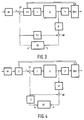
- FIG. 3 A variant of the hybrid encoder according to FIG. 2 is shown in FIG. 3.
- the matrix transformation with low-pass character takes place at the output of the subtractor SR first by an operation unit FTI and then the transformation of the difference blocks into the wave number range with the unit F.
- the operation unit FTI at the output of the subtractor SR carries out the low-pass filtering in the spatial area, just like the second unit FTI, which transforms the data blocks from the image memory BS and feeds the adder AR.
- This variant has the advantage that two identical units FTI can be used in the hybrid encoder and therefore, for example, only one transformation matrix needs to be stored.
- the low-pass filtering of the blocks of the video signal is carried out by a unit T1 before the difference is formed by the subtractor SR.
- Another unit T2 immediately follows the output of the image memory BS. Both units T1 and T2 carry out the low-pass filtering in the spatial area, that is to say contain matrices which formally correspond to the matrix w specified above or powers of these.
- the setting or control of the cut-off frequencies of the units T1 and T2 is carried out - as in the other variants with two low-pass units - in such a way that corresponding data blocks experience the same filtering; the cut-off frequencies are the same for both low-pass units.
- a further improvement in the quality of the transmitted images can be achieved without increasing the transmission bit rate if the low-pass effect of the unit T1 is less than the low-pass effect of the unit T2.
- a lower low-pass effect means, for example, a higher cut-off frequency; the low-pass effect of a unit becomes zero when the cutoff frequency becomes infinitely large.
- the limit frequencies of the units T1 and T2 are controlled, for example by the displacement vector, the limit frequency of the unit T1 must always be selected to be greater than the limit frequency of the unit T2.
- both units T1 and T2 have no effect, that is to say they have infinitely large cutoff frequencies.
- the following empirically found fact is important for the further reasoning: If one carries out the above-mentioned special, areal Fourier transformation with the data blocks coming from the unit PP and also carries out the same transformation with the data blocks that come from the image memory BS, then one finds that between the coefficients that are too high Frequencies (better: wavenumbers) and corresponding data blocks belong to each other, there is only a slight correlation.
- the high frequency components of the blocks that come from the unit PP are therefore statistically independent of the high frequency components of the data blocks that come from the image memory BS.
- the subtractor SR forms the difference between the two blocks and the difference block is transformed by the unit F Fourier, larger values result for the high frequency components of the difference blocks - because of the statistical independence of the summands - than for each of the blocks alone.
- the high frequency component of the blocks that come from the image memory BS is damped by the unit T2 - which now has a finite cutoff frequency. This improves the image quality on the receiver side because unsuitable image components are no longer used for coding on the transmitter side. Among other things, this leads to a smaller number of bits required for coding the differential blocks.
- a band limitation of the signal to be coded is carried out by the operation unit T1. It must be carried out in such a way that the cut-off frequency of the unit T1 acting as a low-pass filter is above the cut-off frequency of the unit T2.
- the band limitation of the blocks coming from the unit PP reduces the annoying quantization noise at the expense of image sharpness; however, this disadvantage is less troublesome.
- the low-pass characteristic of the unit T2 is determined both from the degree of correlation between the coefficients of the blocks coming from the unit PP and the blocks coming from the image memory BS and from the low-pass characteristic of the unit T1.
- the blocks for decoding are reshaped in a manner similar to that for decoding by means of a hybrid decoder, namely that a variant of a hybrid decoder according to the invention essentially consists of a part of the corresponding variant of the hybrid encoder.
- a hybrid decoder contains all units that are in the feedback loop of the corresponding hybrid encoder.
- the hybrid decoder contains, in addition to an input buffer memory, a unit IF for transforming the data blocks back into space, an adder AR an image memory BS and an operation unit FTI for filtering; all of these units are connected to one another in the same way as the corresponding units of the hybrid encoder according to FIG. 2.
- the output of the adder AR on the receiver side is at the same time the output of the hybrid decoder.
- the blocks applied here are subjected to a further treatment, which essentially includes the resolution of the block structure, so that the signal can be made visible on a monitor as a result of video images.
Landscapes
- Engineering & Computer Science (AREA)
- Multimedia (AREA)
- Signal Processing (AREA)
- Compression Or Coding Systems Of Tv Signals (AREA)
Description
Die Erfindung bezieht sich auf einen Hybrid-Codierer für Videosignale
- mit einer Funktionseinheit Zur Unterteilung der Daten eines Videobildes in gleich große Datenblöcke,
- mit einem Subtrahierer zur Subtraktion jedes von der Funktionseinheit gelieferten Datenblockes von einem entsprechenden, über einen Rückkopplungsweg geführten ans dem vorherigen Videobild abgeleiteten Datenblock,
- mit einer ersten Operationseinheit zur Durchführung einer Cosinus-Transformation, die mit dem Ausgang oder dem Eingang des ein Differenzbild liefernden Subtrahierers gekoppelt ist,
- mit einem im Rückkopplungsweg enthaltenen zur Speicherung von Datenblöcken vorgesehenen Bildspeicher, der einerseits mit dem Subtrahierer und andererseits mit einem Addierer zur Addition der über den Rückkopplungsweg gegebenen Datenblöcke mit entsprechenden aus dem Bildspeicher abgeleiteten Datenblöcken gekoppelt ist.
- with a functional unit for dividing the data of a video image into data blocks of the same size,
- with a subtractor for subtracting each data block supplied by the functional unit from a corresponding data block guided via a feedback path and derived from the previous video image,
- with a first operation unit for carrying out a cosine transformation, which is coupled to the output or the input of the subtractor providing a difference image,
- with an image memory provided in the feedback path for storing data blocks, which is coupled on the one hand to the subtractor and on the other hand to an adder for adding the data blocks given via the feedback path to corresponding data blocks derived from the image memory.
Ein Hybrid-Codierer mit den angegebenen Merkmalen ist in einem Tagungsbericht (Draft version Document Sim 85/78 Report COST 211 bis Simulation Subgroup Meeting, Stockholm, 10. bis 11. Dezember 1985) der COST-Gruppe beschrieben. Ein Prinzipschaltbild des bekannten Hybrid-Codierers ist in Fig. 1 dargestellt. Der Hauptzweck des gezeigten Codierers ist der, die von einer Video-Datenquelle kommenden Videodaten möglichst mit geringem Informationsverlust in ein Signal mit möglichst geringer Bitrate umzucodieren.A hybrid encoder with the specified features is described in a conference report (Draft version Document Sim 85/78 Report COST 211 to Simulation Subgroup Meeting, Stockholm, December 10 to 11, 1985) of the COST group. A basic circuit diagram of the known hybrid encoder is shown in FIG. 1. The main purpose of the encoder shown is to recode the video data coming from a video data source with as little information loss as possible into a signal with the lowest possible bit rate.
Bei diesem Vorgang werden zwei Codierungsprinzipien - daher der Name Hybrid-Codierer - angewendet:Two coding principles - hence the name hybrid encoder - are used in this process:
Das Interframe-Prinzip, bei dem die Korrelation zwischen zeitlich aufeinanderfolgenden Videobildern (diese Bezeichnung wird hier für Voll- und Teilbilder verwendet) ausgenutzt wird, und das Intraframe-Prinzip, bei dem die Korrelation der Videodaten innerhalb eines Videobildes ausgenutzt wird.The interframe principle, in which the correlation between temporally successive video images (this term is used here for full and partial images) is used, and the intra-frame principle, in which the correlation of the video data within a video image is used.
Vor dem eigentlichen Codierungsprozeß ist eine Aufbereitung der Daten erforderlich. Diese Aufbereitung wird bei dem Hybrid-Codierer nach Fig. 1 durch eine Funktionseinheit PP (preprocessing) übernommen. Die Daten werden in Blöcken an den Codierer übergeben. Ein solcher Videodatenblock enthält die Daten bestimmter Bildpunkte eines Videobildes, die als Elemente einer quadratischen Zahlenmatrix aufgefaßt werden (zur Bedeutung der hier verwendeten Begriffe im Zusammenhang mit Zahlenmatritzen vgl. Wigner, E.P.: Group Theory; Academic Press New York and London 1959, Seite 1 bis 30). So kann z.B. ein Datenblock aus den Chrominanzwerten der ersten acht Bildpunkte der ersten acht Zeilen eines Videobildes bestehen. Durch die Funktionseinheit PP wird jedes Videobild in gleich große Datenblöcke zerlegt. Die Zerlegungsvorschrift enthält auch die Zuordnung einer Kennung zu jedem Datenblock. Der eben als Beispiel angeführte Datenblock könnte z.B. durch b₁₁ symbolisiert und gekennzeichnet werden. Datenblöcke von aufeinanderfolgenden Videobildern, die die gleiche Kennung haben, werden hier als sich entsprechende Datenblöcke bezeichnet.The data must be prepared before the actual coding process. This processing is adopted in the hybrid coder of FIG. 1 by a functional unit PP (p re p rocessing). The data is transferred to the encoder in blocks. Such a video data block contains the data of certain pixels of a video image, which are interpreted as elements of a square number matrix (for the meaning of the terms used here in connection with number matrices, see Wigner, EP: Group Theory; Academic Press New York and London 1959, page 1 to 30). For example, a data block can consist of the chrominance values of the first eight pixels of the first eight lines of a video image. The functional unit PP divides each video image into data blocks of the same size. The decomposition rule also contains the assignment of an identifier to each data block. The data block just given as an example could be symbolized and identified by b ₁₁, for example. Data blocks from successive video images that have the same identifier are referred to here as corresponding data blocks.
Mit der gleichen Bezeichnung sollen auch Datenblöcke aufeinanderfolgender Videobilder gemeint sein, deren Informationsinhalte die größte Übereinstimmung haben. In diesem Sinne sich entsprechende Datenblöcke spielen bei Hybrid-Codierern eine Rolle, bei denen ein sogenanntes Clockmatching vorgenommen wird. Auf diese Variante von Hybrid-Codierern soll jedoch nicht näher eingegangen werden.The same designation is also intended to mean data blocks of successive video images, their information content have the greatest match. In this sense, corresponding data blocks play a role in hybrid encoders, in which clock matching is carried out. However, this variant of hybrid encoders will not be discussed in more detail.
Bei der Übergabe eines Datenblockes, z.B. des Datenblockes b₁₁ an einen Eingang eines Subtrahierers SR, wird gleichzeitig der entsprechende Datenblock - symbolisiert z.B. durch b ₁₁ - des vorangegangenen Videobildes aus einem Bildspeicher BS an den anderen Eingang des Subtrahierers SR gegeben. Der Subtrahierer SR bildet die Differenz zwischen den beiden Blöcken im Sinne der Differenz zwischen zwei Matritzen (vgl. Wigner l.c., Seite 7); dieser Differenzblock wird nun weiteren Operationen unterworfen.When a data block, for example the data block b ₁₁ to an input of a subtractor SR, the corresponding data block - symbolized, for example, by b ₁₁ - of the previous video image from an image memory BS is given to the other input of the subtractor SR. The subtractor SR forms the difference between the two blocks in the sense of the difference between two matrices (cf. Wigner lc, page 7); this difference block is now subjected to further operations.
Eine erste Operationseinheit F nimmt mit jedem Differenzblock eine Ähnlichkeitstransformation im Sinne einer Matrixtransformation vor (vgl. Wigner l.c., Seite 9). Sei a das Symbol für die Transformationsmatrix der Einheit F und d₁₁ das Symbol für die Matrix des Differenzblockes - oder einfacher für den Differenzblock - so liegt nach der Transformation am Ausgang der Einheit F der Block ![]()
![]()
Anschließend durchläuft das transformierte Signal einen Quantisierer Q, der nochmals für eine Datenreduktion sorgt. Damit das gesamte Signal mit konstanter Bitrate an einen Empfänger übertragen werden kann, ist ein Pufferspeicher P vorgesehen. Ein Multiplexer MUX verschachtelt das aus dem Pufferspeicher P ausgelesene Nutzsignal mit Steuerinformationen, die im vorliegenden Falle unter anderem zur Einstellung eines Quantisierers auf der Empfängerseite dienen (es handelt sich hier um adaptive Quantisierer). Nach der Quantisierung wird das Signal auch über einen Rückkopplungsweg an den Eingang des Hybrid-Codierers zurückgeschleift. Zunächst wird der durch den Quantisierer Q veränderte Block D₁₁ durch eine nicht eingezeichnete Regenerationseinheit so weit regeneriert, daß er bis auf Rundungsfehler mit dem ursprünglichen Block D₁₁ übereinstimmt. Sodann wird er durch eine zweite Operationseinheit IF mit der Transformationsmatrix a⁻¹ wieder in den Differenzblock d₁₁ (ebenfalls bis auf Rundungsfehler) zurücktransformiert. Ein Addierer AR addiert zu diesem Block - wegen der Verbindung eines Ausganges A des Bildspeichers BS mit einem Eingang des Addierers AR - den Datenblock b ₁₁, mit dem durch den Subtrahierer SR der Differenzblock d₁₁ gebildet wurde. Eventuelle Verzögerungen wegen endlicher Laufzeiten werden entweder durch Verzögerungsglieder oder Taktverschiebungen (beides in Fig. 1 nicht angedeutet) ausgeglichen.The transformed signal then passes through a quantizer Q, which again ensures data reduction. So that the entire signal with constant bit rate on a buffer P can be provided. A multiplexer MUX interleaves the useful signal read out from the buffer memory P with control information which, in the present case, serves, among other things, to set a quantizer on the receiver side (these are adaptive quantizers). After quantization, the signal is also looped back to the input of the hybrid encoder via a feedback path. First, the block D ₁₁ modified by the quantizer Q is regenerated by a regeneration unit (not shown) to such an extent that it matches the original block D ₁₁ except for rounding errors. Then it is transformed by a second operation unit IF with the transformation matrix a ⁻¹ back into the difference block d ₁₁ (also except for rounding errors). An adder AR adds to this block - because of the connection of an output A of the image memory BS to an input of the adder AR - the data block b ₁₁, with which the difference block d ₁₁ was formed by the subtractor SR. Any delays due to finite running times are compensated for either by delay elements or clock shifts (neither of which is indicated in FIG. 1).
Wie sich leicht überprüfen läßt, ergibt sich am Ausgang des Addierers AR der Datenblock b₁₁ (bis auf Rundungsfehler) des gerade über die Funktionseinheit PP zugeführten Videobildes. Dieser Datenblock wird über einen Eingang E des Bildspeichers BS in ihn eingelesen und übernimmt dort die Rolle des Datenblockes b ₁₁, der nun gelöscht wird.As can be easily checked, the data block b ₁₁ at the output of the adder AR (except for rounding errors) of the video image just supplied via the functional unit PP. This data block is read into it via an input E of the image memory BS and takes on the role of the data block b ₁₁ there, which is now deleted.
Bei dem bekannten Hybrid-Codierer hängt die Bitratenreduktion entscheidend von der Ausgestaltung des Quantisierers Q ab. Sind die Quantisierungsintervalle groß, gilt das zwar auch für die Bitratenreduktion, jedoch vermindert sich die Bildqualität in besonders störender Weise durch die hohen Quantisierungsfehler. Es kann z.B. auf dem Bildschirm ein schachbrettartiges Muster entstehen, das von der Aufteilung eines Videobildes in Blöcke herrührt oder es entstehen und vergehen ständig wechselnde Strukturen (Artefakte), die zur völligen Entstellung des wiedergegebenen Bildes führen können.In the known hybrid encoder, the bit rate reduction depends crucially on the design of the quantizer Q. If the quantization intervals are large, the following applies this also applies to bit rate reduction, but the image quality is particularly annoying due to the high quantization errors. For example, a checkerboard-like pattern can arise on the screen, which results from the division of a video image into blocks, or there are constantly changing structures (artifacts) that can lead to the complete distortion of the reproduced image.
Um den Quantisierungsfehler wenigstens bei empfindlichen Signalanteilen zu verringern, werden z.B. adaptive Quantisierer verwendet, also Quantisierer, deren Kennlinie durch das Videosignal verändert wird. Der Aufwand ist unter anderem deshalb erheblich, weil zusätzliche Informationen über den Zustand des Quantisierers an den Empfänger übertragen werden müssen.In order to reduce the quantization error at least for sensitive signal components, e.g. uses adaptive quantizers, i.e. quantizers whose characteristic is changed by the video signal. The effort is considerable, among other things, because additional information about the state of the quantizer has to be transmitted to the receiver.
Die von der Funktionseinheit PP und von dem Bildspeicher BS (vgl. Fig. 1) kommenden Datenblöcke werden - wie oben erwähnt - einer speziellen, flächenhaften Fourier-Transformation (Cosinus-Transformation) unterzogen. Bei empirischen Untersuchungen hat sich herausgestellt, daß zwischen den Koeffizienten, die zu hohen Frequenzen (besser: Wellenzahlen) und sich einander entsprechenden Datenblöcken gehören nur eine geringe Korrelation besteht. Die hohen Frequenzanteile der Datenblöcke, die von der Funktionseinheit PP kommen, sind also statistisch unabhängig von den hohen Frequenzanteilen der Datenblöcke, die vom Bildspeicher BS kommen. Da jedoch der Subtrahierer SR die Differenz beider Datenblöcke bildet, und der Differenzblock durch die Operationseinheit F cosinustransformiert wird, ergeben sich für die hohen Frequenzanteile der Differenzblöcke - wegen der statistischen Unabhängigkeit der Summanden - größere Werte als für jeden der Datenblöcke alleine. Es ergibt sich hierdurch eine Verschlechterung der Bildqualität.The data blocks coming from the functional unit PP and from the image memory BS (cf. FIG. 1) are - as mentioned above - subjected to a special, areal Fourier transformation (cosine transformation). Empirical studies have shown that there is only a slight correlation between the coefficients belonging to high frequencies (better: wavenumbers) and corresponding data blocks. The high frequency components of the data blocks that come from the functional unit PP are therefore statistically independent of the high frequency components of the data blocks that come from the image memory BS. However, since the subtractor SR forms the difference between the two data blocks and the difference block is cosine-transformed by the operating unit F, larger values result for the high frequency components of the difference blocks - because of the statistical independence of the summands - than for each of the data blocks alone. This results in a deterioration in the image quality.
Der Erfindung liegt daher die Aufgabe zugrunde, einen Hybrid-Codierer der eingangs genannten Art zu schaffen, durch den eine verbesserte Bildqualität erreicht wird.The invention is therefore based on the object of providing a hybrid encoder of the type mentioned at the outset, by means of which an improved image quality is achieved.
Diese Aufgabe wird dadurch gelöst, daß mit dem Bildspeicher Mittel gekoppelt sind, die zur Durchführung einer Matrixoperation mit Tiefpaßcharakter der von dem Bildspeicher gelieferten Datenblöcke vorgesehen ist.This object is achieved in that means are coupled to the image memory which are provided for carrying out a matrix operation with a low-pass character of the data blocks supplied by the image memory.
Fin solches Mittel kann eine Tiefpaßeinheit zur Durchführung einer Matrixoperation mit Tiefpaßcharakter sein, die unmittelbar mit dem Ausgang oder Eingang des Bildspeichers verbunden ist. Die Tiefpaßeinheit dämpft die hohen Frequenzanteile der Datenblöcke, die aus dem Bildspeicher oder dem Addierer kommen. Hierdurch wird die Bildqualität auf der Empfängerseite verbessert, weil für die Codierung auf der Senderseite ungeeignete Bildanteile nicht mehr verwendet werden. Das führt unter anderem zu einer geringeren Zahl der für die Codierung der Differenzblöcke erforderlichen Bits.Such a means can be a low-pass unit for performing a matrix operation with a low-pass character, which is directly connected to the output or input of the image memory. The low-pass unit attenuates the high frequency components of the data blocks that come from the image memory or the adder. This improves the image quality on the receiver side because unsuitable portions of the image are no longer used for coding on the transmitter side. Among other things, this leads to a smaller number of bits required for coding the differential blocks.
Als Mittel kann auch eine Einheit vor bzw. hinter der Operationseinheit zur Durchführung einer Cosinus-Transformation und eine Operationseinheit zwischen Bildspeicher und Addierer angeordnet sein.A unit can also be arranged in front of or behind the operation unit for performing a cosine transformation and an operation unit between the image memory and adder.
In einer Weiterbildung der Erfindung ist vorgesehen, daß eine mit der ersten, dem Subtrahierer nachgeschaltete Operationseinheit gekoppelte, im Rückkopplungsweg enthaltene zweite Operationseinheit zur Durchführung einer inversen Cosinus-Transformation vor dem Addierer angeordnet ist, daß zwischen Addierer und dem Eingang des Bildspeicher oder unmittelbar hinter dem Ausgang des Bildspeichers eine Tiefpaßeinheit angeordnet ist und daß zwischen der Funktionseinheit zur Unterteilung der Daten eines Videobildes in gleich große Datenblöcke und dem Subtrahierer eine weitere Tiefpaßeinheit zur Durchführung einer Matrixoperation mit Tiefpaßcharakter der Datenblöcke des Videobildes angeordnet ist.In a further development of the invention it is provided that a second operation unit, coupled to the first operation unit connected downstream of the subtractor and contained in the feedback path, for carrying out an inverse cosine transformation is arranged in front of the adder, that between the adder and the input of the image memory or immediately behind the Output of the image memory a low-pass unit is arranged and that a further low-pass unit for performing a matrix operation with low-pass character of the data blocks of the video image is arranged between the functional unit for dividing the data of a video image into data blocks of equal size and the subtractor.
Hierbei dient die weitere Tiefpaßeinheit zur Bandbegrenzung der von der Funktionseinheit kommenden Datenblöcke. Die Tiefpaßwirkung der Tiefpaßeinheit, die zwischen der Funktionseinheit und dem Subtrahierer liegt, ist dabei geringer als die Tiefpaßwirkung der Tiefpaßeinheit, die unmittelbar hinter dem Ausgang des Bildspeichers angeordnet ist. Die Bandbegrenzung der von der Funktionseinheit kommenden Datenblöcke reduziert das störende Quantisierungsrauschen auf Kosten der Bildschärfe (Unschärfe). Eine solche Unschärfe ist jedoch weniger störend als die eingangs genannten Störungen aufgrund des Quantisierungsfehlers.Here, the further low-pass unit serves to limit the band of the data blocks coming from the functional unit. The low-pass effect of the low-pass unit, which lies between the functional unit and the subtractor, is less than the low-pass effect of the low-pass unit, which is arranged directly behind the output of the image memory. The band limitation of the data blocks coming from the functional unit reduces the annoying quantization noise at the expense of image sharpness (blurring). However, such blurring is less disturbing than the disturbances mentioned at the outset due to the quantization error.
In einer anderen Weiterbildung der Erfindung ist vorgesehen, daß eine mit der ersten, dem Subtrahierer nachgeschaltete Operationseinheit gekoppelte, im Rückkopplungsweg enthaltene zweite Operationseinheit zur Durchführung einer inversen Cosinus-Transformation vor dem Addierer angeordnet ist, daß direkt hinter der ersten Operationseinheit eine Tiefpaßeinheit angeordnet ist und daß vor dem Addierer eine vierte Operationseinheit zum Empfang der Datenblöcke vom Bildspeicher, zur Durchführung einer Matrixoperation mit Tiefpaßcharakter der vom Bildspeicher gelieferten Datenblöcke und zur Lieferung der gefilterten Datenblöcke an den Addierer angeordnet ist.In another development of the invention, it is provided that a second operation unit coupled to the first operation unit connected downstream of the subtractor and contained in the feedback path for performing an inverse cosine transformation is arranged in front of the adder, that a low-pass unit is arranged directly behind the first operation unit and that a fourth operation unit for receiving the data blocks from the image memory, for performing a matrix operation with a low-pass character of the data blocks supplied from the image memory and for supplying the filtered data blocks to the adder is arranged in front of the adder.
Die hohen Frequenzanteile der Datenblöcke vom Bildspeicher werden durch die Tiefpaßeinheit und die vierte Operationseinheit gedämpft. Zusätzlich bewirkt die Tiefpaßeinheit auch eine Bandbegrenzung der von der Funktionseinheit stammenden Datenblöcke. Hierdurch wird ebenfalls das störende Quantisierungsrauschen auf Kosten der Bildschärfe reduziert.The high frequency components of the data blocks from the image memory damped by the low-pass unit and the fourth operation unit. In addition, the low-pass unit also limits the data blocks originating from the functional unit. This also reduces the annoying quantization noise at the expense of sharpness.
Als Matrix für die Tiefpaßeinheit, die zur Durchführung einer Matrixoperation mit Tiefpaßcharakter vorgesehen ist, kann eine Diagonalmatrix dienen.A diagonal matrix can serve as a matrix for the low-pass unit, which is provided for carrying out a matrix operation with a low-pass character.
Weiter ist auch möglich, daß die Matrizen der Tiefpaßeinheit und der vierten Operationseinheit adaptiv verändert werden.It is also possible for the matrices of the low-pass unit and the fourth operation unit to be changed adaptively.
In einer weiteren Fortbildung der Erfindung ist vorgesehen, daß eine mit der ersten, dem Subtrahierer nachgeschaltete Operationseinheit gekoppelte, im Rückkopplungsweg enthaltene zweite Operationseinheit zur Durchführung einer inversen Cosinus-Transformation vor dem Addierer angeordnet ist, daß zwischen dem Subtrahierer und der ersten Operationseinheit eine Tiefpaßeinheit angeordnet ist und daß vor dem Addierer eine weitere Operationseinheit zum Empfang der Datenblöcke vom Bildspeicher, zur Durchführung einer Matrixoperation mit Tiefpaßcharakter der vom Bildspeicher gelieferten Datenblöcke und zur Lieferung der gefilterten Datenblöcke an den Addierer angeordnet ist.In a further development of the invention, it is provided that a second operation unit coupled to the first operation unit connected downstream of the subtractor and contained in the feedback path for carrying out an inverse cosine transformation is arranged in front of the adder, and that a low-pass unit is arranged between the subtractor and the first operation unit and that a further operation unit for receiving the data blocks from the image memory, for performing a matrix operation with a low-pass character of the data blocks supplied from the image memory and for supplying the filtered data blocks to the adder is arranged in front of the adder.
Die hohen Frequenzanteile der Datenblöcke vom Bildspeicher werden durch die Tiefpaßeinheit und die weitere Operationseinheit gedämpft. Zusätzlich bewirkt die Tiefpaßeinheit auch eine Bandbegrenzung der von der Funktionseinheit stammenden Datenblöcke. Hierdurch wird ebenfalls das störende Quantisierungsrauschen auf Kosten der Bildschärfe reduziert.The high frequency components of the data blocks from the image memory are damped by the low-pass unit and the further operation unit. In addition, the low-pass unit also limits the data blocks originating from the functional unit. This also eliminates the annoying quantization noise at the expense of sharpness reduced.
Die Wirkungsweise der Operationseinheiten mit Tiefpaßcharakter wird dabei in Abhängigkeit vom Füllstand eines mit dem Ausgang der ersten Operationseinheit gekoppelten Pufferspeichers oder in Abhängigkeit vom Displacement-Vektor oder in Abhängigkeit von beidem verändert.The mode of operation of the low-pass operation units is changed depending on the fill level of a buffer memory coupled to the output of the first operation unit, or depending on the displacement vector, or both.
In einer anderen Weiterbildung der Erfindung ist vorgesehen, daß die erste Operationseinheit zwischen der Funktionseinheit zur Unterteilung der Daten eines Videosignals in gleich große Datenblöcke und dem Subtrahierer angeordnet ist, daß die Tiefpaßeinheit mit dem Ausgang des Subtrahierers gekoppelt ist und daß vor dem Addierer eine weitere Tiefpeßeinheit zum Empfang der Datenblöcke vom Bildspeicher, zur Durchführung einer Matrixoperation mit Tiefpaßcharakter der vom Bildspeicher gelieferten Datenblöcke und zur Lieferung der gefilterten Datenblöcke an den Addierer angeordnet ist.Another development of the invention provides that the first operation unit is arranged between the functional unit for dividing the data of a video signal into data blocks of the same size and the subtractor, that the low-pass unit is coupled to the output of the subtractor, and that another low-pressure unit is located in front of the adder is arranged to receive the data blocks from the image memory, to carry out a matrix operation with a low-pass character of the data blocks supplied by the image memory and to supply the filtered data blocks to the adder.
Bei dieser Weiterbildung werden die hohen Frequenzanteile der Datenblöcke vom Bildspeicher durch zwei Tiefpaßeinheiten gedämpft. Zusätzlich bewirkt die Tiefpaßeinheit vor dem Addierer auch eine Bandbegrenzung der von der Funktionseinheit stammenden Datenblöcke. Hierdurch wird ebenfalls das störende Quantisierungsrauschen auf Kosten der Bildschärfe reduziert. Da die erste Operationseinheit, die die Cosinus-Transformation durchführt, zwischen Funktionseinheit und Subtrahierer angeordnet ist, wird keine weitere Operationseinheit im Rückkopplungsweg für eine inverse Cosinus-Transformation benötigt.In this development, the high frequency components of the data blocks from the image memory are damped by two low-pass units. In addition, the low-pass unit upstream of the adder also limits the data blocks originating from the functional unit. This also reduces the annoying quantization noise at the expense of sharpness. Since the first operation unit, which carries out the cosine transformation, is arranged between the functional unit and the subtractor, no further operation unit is required in the feedback path for an inverse cosine transformation.
Weiter ist ein Hybrid-Decodierer zur Decodierung von von einem Hybrid-Codierer codierten Videosignal vorgesehen. Dieser enthält eine Operationseinheit, die zum Empfang von gleich großen Datenblöcken des Videobildes, zur Durchführung einer inversen Cosinus-Transformation und zur Lieferung von transformierten Datenblöcken vorgesehen ist, eine die transformierten Datenblöcke an einem Eingang empfangenen Addierer, dessen Ausgang über einen Bildspeicher mit seinem anderen Eingang gekoppelt ist, und eine zwischen dem Ausgang des Bildspeichers und dem anderen Eingang des Addierers angeordnete Operationseinheit zur Durchführung einer Matrixoperation mit Tiefpaßcharakter der vom Bildspeicher gelieferten Datenblöcke.A hybrid decoder is also provided for decoding video signals encoded by a hybrid encoder. This contains one Operation unit which is provided for receiving data blocks of the same size of the video image, for carrying out an inverse cosine transformation and for the delivery of transformed data blocks, an adder which receives the transformed data blocks at an input, the output of which is coupled to its other input via an image memory, and an operating unit arranged between the output of the image memory and the other input of the adder for performing a matrix operation with a low-pass character of the data blocks supplied by the image memory.
Anhand der Figuren und Beispielen sollen Lösungsvarianten der gestellten Aufgabe näher erläutert werden.
- Fig. 1 zeigt einen Hybrid-Codierer nach dem Stand der Technik und
- Fig. 2 bis Fig. 4 zeigen Hybrid-Codierer mit erfindungsgemäßen Schaltungsmerkmalen.
- Fig. 1 shows a hybrid encoder according to the prior art and
- FIGS. 2 to 4 show hybrid encoders with circuit features according to the invention.
In allen Figuren sind funktionsgleiche Einheiten mit gleichen Bezugszeichen versehen.In all figures, functionally identical units are provided with the same reference symbols.
Fig. 1 ist in der Beschreibungseinleitung ausführlich erläutert worden, so daß hier auf diese Figur nicht nocheinmal eingegangen zu werden braucht.Fig. 1 has been explained in detail in the introduction to the description, so that there is no need to go into this figure again here.
Fig. 2 unterscheidet sich von der Fig. 1 lediglich durch zwei Operationseinheiten, nämlich T und FTI. Die Bezeichnungen für die restlichen Einheiten sind die gleichen wie in Fig. 1. Die Operationseinheit T liegt zwischen der Operationseinheit F und dem Quantisierer Q, während die Operationseinheit FTI das Ausgangssignal des Bildspeichers BS in dem weiter unten erläuterten Sinne verformt und dann an einen Eingang des Addierers AR weitergibt.Fig. 2 differs from Fig. 1 only by two operation units, namely T and FTI. The designations for the remaining units are the same as in FIG. 1. The operation unit T lies between the operation unit F and the quantizer Q, while the operation unit FTI the output signal of the image memory BS deformed in the sense explained below and then passed on to an input of the adder AR.
Zur weiteren Erläuterung sei wieder der Einfachheit halber angenommen, daß der Datenblock b₁₁ dem Subtrahierer SR über die Funktionseinheit PP zugeführt wird, während gleichzeitig am Ausgang A des Bildspeichers BS der Datenblock b₁₁ anliegt. Der Subtrahierer SR bildet sodann den Differenzblock ![]()
![]()
![]()
![]()
![]()
![]()
Die Deutung der bisher angegebenen Formeln liegt auf der Hand: Mit der Matrix h wird eine Tiefpaßfilterung der durch die Einheit F transformierten Blöcke vorgenommen, mit der Matrix w die gleiche Filterung mit den nicht transformierten Blöcken. Die Tiefpaßfilterung durch die Einheiten T und FTI wird also in verschiedenen "Räumen" vorgenommen, nämlich durch die Einheit FTI im Ortsraum (bzw. Ortsbereich) und durch die Einheit T im Wellenzahlraum (bzw. Wellensahlbereich); das akustische Analogon wäre eine Signalumformung im Frequenzbereich (z.B. eine Tiefpaßfilterung) und deren Darstellung im Zeitbereich (als Faltungsintegral). Wegen dieser unterschiedlichen "Räume" sind auch die Transformationsmatrizen - wie oben dargelegt - für die Einheiten T und FTI unterschiedlich, so daß unterschiedliche Matrizen berechnet und abgespeichert werden müssen.The interpretation of the formulas given so far is obvious: with the matrix h , low-pass filtering of the blocks transformed by the unit F is carried out, with the matrix w the same filtering with the non-transformed blocks. The low-pass filtering by the units T and FTI is thus carried out in different "rooms", namely by the unit FTI in the local area (or local area) and by the unit T in the wave number space (or wave number area); the acoustic analogue would be a signal conversion in the frequency domain (eg low-pass filtering) and its representation in the time domain (as a convolution integral). Because of these different "spaces", the transformation matrices - as explained above - are different for the units T and FTI, so that different matrices have to be calculated and stored.
Die tiefpaßgefilterten Blöcke werden in den Bildspeicher BS eingelesen, es wird also ein unscharfes Bild abgespeichert und auch übertragen. Diese Bildungschärfe ist der Preis, der für die Unterdrückung der Quantisierungsfehler zu zahlen ist.The low-pass filtered blocks are read into the image memory BS, so an unsharp image is stored and also transmitted. This sharpness of formation is the price to be paid for the suppression of quantization errors.
Ist die mit der Tiefpaßfilterung durch die Matrix h verbundene Grenzfrequenz tief genug, so kann der Quantisierer Q z.B. ein nicht adaptiver Quantisierer sein oder auch ganz entfallen, wenn die Bitraten gering genung sind.If the cut-off frequency associated with the low-pass filtering by the matrix h is low enough, the quantizer Q can, for example, be a non-adaptive quantizer or can be omitted entirely if the bit rates are low enough.
Bei den weiteren Erläuterungen wird angenommen, daß die Operationseinheit F mit Hilfe der Matrix a eine Cosinus-Transformation (vgl. hierzu z.B. Pratt, W.K.: Digital Image Processing; John Wiley & Sons 1978, S. 242-247) durchführt. Die Matrix a ist also dem Fachmann in allen Einzelheiten bekannt. Für diesen Sonderfall läßt sich für h eine besonders einfache Matrix, nämlich eine Diagonalmatrix (vgl. Wigner l.c., S. 8), angeben. Filtermatrizen, die eine Filterung der Blöcke im Ortsbereich (akustisches Analogon: Zeitbereich) vornehmen, haben formal die gleiche Struktur wie folgende Hilfsmatrix m :
Ab der zweiten Zeile der Matrix m sind drei Elemente -hier 1, 0, 1 - mit jeder weiteren Zeile um eine Stelle nach rechts verschoben; alle weiteren Elemente der Zeile sind Null. Die ersten beiden Elemente der ersten Zeile und die letzten beiden Elemente der letzten Zeile bestehen aus Einsen, während auch hier alle anderen Elemente aus Nullen bestehen. Die Zeilenzahl der Matrix m (sie stimmt mit der Spaltenzahl überein) ist so groß wie die Zeilenzahl bzw. Spaltenzahl der zu verarbeitenden Blöcke.In the further explanations, it is assumed that the operating unit F uses the matrix a to carry out a cosine transformation (cf., for example, Pratt, WK: Digital Image Processing; John Wiley & Sons 1978, pp. 242-247). The matrix a is therefore known to the person skilled in all details. For this special case, a particularly simple matrix, namely a diagonal matrix (cf. Wigner lc, p. 8), can be specified for h . Filter matrices that filter the blocks in the spatial area (acoustic analog: time domain) have the same structure as the following auxiliary matrix m :
From the second line of the matrix m , three elements - here 1, 0, 1 - are shifted one place to the right with each additional line; all other elements of the line are zero. The first two elements of the first line and the last two elements of the last line consist of ones, while here, too, all other elements consist of zeros. The number of lines in the matrix m (it corresponds to the number of columns) is as large as the number of lines or number of columns in the blocks to be processed.
Wählt man nun als Matrix w die Matrix
mit I als Einheitsmatrix, so ergibt sich für k kleiner als 1 jedoch größer oder gleich 0,5 eine ganze Klasse von Filtermatrizen mit Tiefpaßcharakter. Je kleiner k ist, umso tiefer liegt die Grenzfrequenz bei der Tiefpaßfilterung. Jede Potenz von w ergibt ebenfalls eine Matrix mit Tiefpaßcharakter.Now choose the matrix w as the matrix
with I as the unit matrix, for k less than 1 but greater than or equal to 0.5, a whole class of filter matrices with a low-pass character results. The smaller k is, the lower the cut-off frequency for low-pass filtering. Each power of w also results in a matrix with a low-pass character.
Löst man nun den oben angegebenen Zusammenhang zwischen w und h nach h auf, so ergibt sich für ![]()
![]()
Die Tiefpaßfilterung kann dadurch verfeinert werden, daß die Matrizen h und w in Abhängigkeit vom Signal verändert werden, die Filtrerung also adaptiv erfolgt. Dann müssen jedoch für die Decodierung Zusatzinformationen an den Empfänger übertragen werden. Diese Übertragung der Zusatzinformationen ist z.B. durch eine Verbindung der Einheit T mit dem Multiplexer MUX angedeutet. Gleiche Verbindungen bestehen auch zwischen den anderen Einheiten mit Tiefpaßwirkung und dem Multiplexer MUX; sie sind jedoch nicht eingezeichnet. Die Einstellung z.B. der Grenzfrequenzen der Einheiten mit Tiefpaßwirkung ist abhängig vom Füllstand des Pufferspeichers P und vom sogenannten Displacement-Vektor, eine Größe, die den Unterschied zwischen aufeinanderfolgenden Videobildern aufgrund der Bewegung der aufgenommenen Objekte angibt und ebenfalls vom Bildspeicher BS (angedeutet durch die Verbindung der Einheit PP mit dem Bildspeicher BS) bestimmt wird. Angaben über den Füllstand des Pufferspeichers P und die Größe des Displacement-Vektors werden ebenfalls zur ordnungsgemäßen Decodierung an den Empfänger übertragen.The low-pass filtering can be refined by changing the matrices h and w as a function of the signal, so that the filtering is carried out adaptively. Then additional information must be transmitted to the receiver for decoding. This transmission of the additional information is indicated, for example, by a connection of the unit T to the multiplexer MUX. The same connections also exist between the other units with a low-pass effect and the multiplexer MUX; however, they are not shown. The setting, for example, of the cut-off frequencies of the units with a low-pass effect depends on the fill level of the buffer memory P and on the so-called displacement vector, a variable which indicates the difference between successive video images due to the movement of the recorded objects and also from the image memory BS (indicated by the connection of the Unit PP with the image memory BS) is determined. Information about the fill level of the buffer memory P and the size of the displacement vector are also transmitted to the receiver for correct decoding.
Eine Variante des Hybrid-Codierers nach Fig. 2 zeigt Fig. 3. Bei dieser Variante erfolgt am Ausgang des Subtrahierers SR zuerst die Matrixtransformation mit Tiefpaßcharakter durch eine Operationseinheit FTI und dann die Transformation der Differenzblöcke in den Wellenzahlbereich mit der Einheit F. Die Operationseinheit FTI am Ausgang des Subtrahierers SR nimmt die Tiefpaßfilterung im Ortsraum vor, genauso wie die zweite Einheit FTI, die die Datenblöcke aus dem Bildspeicher BS transformiert und dem Addierer AR zuführt. Diese Variante hat den Vorteil, daß zwei identische Einheiten FTI im Hybrid-Codierer verwendet werden können und daher z.B. nur eine Transformationsmatrix abgespeichert zu werden braucht.A variant of the hybrid encoder according to FIG. 2 is shown in FIG. 3. In this variant, the matrix transformation with low-pass character takes place at the output of the subtractor SR first by an operation unit FTI and then the transformation of the difference blocks into the wave number range with the unit F. The operation unit FTI at the output of the subtractor SR carries out the low-pass filtering in the spatial area, just like the second unit FTI, which transforms the data blocks from the image memory BS and feeds the adder AR. This variant has the advantage that two identical units FTI can be used in the hybrid encoder and therefore, for example, only one transformation matrix needs to be stored.
Eine andere, jedoch nicht abgebildete Variante mit dem gleichen Vorteil besteht darin, bei einer Schaltung nach Fig. 2 die Operationseinheit F, die die Fourier-Transformation der Datenblöcke vornimmt, unmittelbar auf die Einheit PP folgen zu lassen, also dem Subtrahierer SR schon transformierte Blöcke zuzuführen. Dann ist an die Stelle der Einheit FTI eine weitere Einheit T zu setzen, während die Einheit IF entfällt. In der Schleife werden auf diese Weise nur Signale im Wellenzahlraum verarbeitet.Another variant, but not shown, with the same advantage is to have the operational unit F, which performs the Fourier transformation of the data blocks, immediately follow the unit PP in a circuit according to FIG. 2, that is to say the subtractor SR already transformed blocks feed. Then another unit T is to be put in place of unit FTI, while unit IF is omitted. In this way, only signals in the wave number space are processed in the loop.
Nach Fig. 4 erfolgt die Tiefpaßfilterung der Blöcke des Videosignals durch eine Einheit T1 vor der Differenzbildung durch den Subtrahierer SR. Eine weitere Einheit T2 folgt unmittelbar auf den Ausgang des Bildspeichers BS. Beide Einheiten T1 und T2 nehmen die Tiefpaßfilterung im Ortsraum vor, enthalten also Matrizen, die formal mit der oben angegebenen Matrix w oder Potenzen davon übereinstimmen.4, the low-pass filtering of the blocks of the video signal is carried out by a unit T1 before the difference is formed by the subtractor SR. Another unit T2 immediately follows the output of the image memory BS. Both units T1 and T2 carry out the low-pass filtering in the spatial area, that is to say contain matrices which formally correspond to the matrix w specified above or powers of these.
Die Einstellung oder Steuerung des Grenzfrequenzen der Einheiten T1 und T2 erfolgt - wie auch bei den anderen Varianten mit zwei Tiefpaßeinheiten - zunächst so, daß einander entsprechende Datenblöcke die gleiche Filterung erfahren; bei beiden Tiefpaßeinheiten sind die Grenzfrequenzen also gleich.The setting or control of the cut-off frequencies of the units T1 and T2 is carried out - as in the other variants with two low-pass units - in such a way that corresponding data blocks experience the same filtering; the cut-off frequencies are the same for both low-pass units.
Bei der Variante nach Fig. 4 läßt sich eine weitere Verbesserung der Qualität der übertragenen Bilder ohne Erhöhung der Übertragungsbitrate erreichen, wenn die Tiefpaßwirkung der Einheit T1 geringer ist als die Tiefpaßwirkung der Einheit T2. Geringere Tiefpaßwirkung bedeutet z.B. eine höhere Grenzfrequenz; die Tiefpaßwirkung einer Einheit wird Null, wenn die Grenzfrequenz unendlich groß wird. Auch bei einer Steuerung der Grenzfrequenzen der Einheiten T1 und T2 z.B. durch den Displacement-Vektor ist die Grenzfrequenz der Einheit T1 immer größer als die Grenzfrequenz der Einheit T2 zu wählen.4, a further improvement in the quality of the transmitted images can be achieved without increasing the transmission bit rate if the low-pass effect of the unit T1 is less than the low-pass effect of the unit T2. A lower low-pass effect means, for example, a higher cut-off frequency; the low-pass effect of a unit becomes zero when the cutoff frequency becomes infinitely large. Even when the limit frequencies of the units T1 and T2 are controlled, for example by the displacement vector, the limit frequency of the unit T1 must always be selected to be greater than the limit frequency of the unit T2.
Es soll nun plausibel gemacht werden, daß sich bei einer solchen Bemessung der Einheiten T1 und T2 eine Verbesserung der Bildqualität gegenüber dem Fall ergibt, in dem beide Einheiten gleich bemessen sind. Zu diesem Zweck sei zunächst angenommen, daß beide Einheiten T1 und T2 wirkungslos sind, also unendlich große Grenzfrequenzen haben. Für die weitere Argumentation ist folgende, empirisch gefundene Tatsache von Bedeutung:
Führt man mit den von der Einheit PP kommenden Datenblöcken die oben erwähnte spezielle, flächenhafte Fourier-Transformation durch und führt die gleiche Transformation auch mit den Datenblöcken durch, die vom Bildspeicher BS kommen, so stellt man fest, daß zwischen den Koerrizienten, die zu hohen Frequenzen (besser: Wellenzahlen) und sich einander entsprechenden Datenblöcken gehören, nur eine geringe Korrelation besteht. Die hohen Frequenzanteile der Blöcke, die von der Einheit PP kommen, sind also statistisch unabhängig von den hohen Frequenzanteilen der Datenblöcke, die vom Bildspeicher BS kommen. Da jedoch der Subtrahierer SR die Differenz beider Blöcke bildet, und der Differenzblock durch die Einheit F Fouriertransformiert wird, ergeben sich für die hohen Frequenzanteile der Differenzblöcke - wegen der statistischen Unabhängigkeit der Summanden - größere Werte als für jeden der Blöcke alleine.It should now be made plausible that such a dimensioning of the units T1 and T2 results in an improvement in the image quality compared to the case in which both units are dimensioned the same. For this purpose it is first assumed that both units T1 and T2 have no effect, that is to say they have infinitely large cutoff frequencies. The following empirically found fact is important for the further reasoning:
If one carries out the above-mentioned special, areal Fourier transformation with the data blocks coming from the unit PP and also carries out the same transformation with the data blocks that come from the image memory BS, then one finds that between the coefficients that are too high Frequencies (better: wavenumbers) and corresponding data blocks belong to each other, there is only a slight correlation. The high frequency components of the blocks that come from the unit PP are therefore statistically independent of the high frequency components of the data blocks that come from the image memory BS. However, since the subtractor SR forms the difference between the two blocks and the difference block is transformed by the unit F Fourier, larger values result for the high frequency components of the difference blocks - because of the statistical independence of the summands - than for each of the blocks alone.
Deshalb wird der hohe Frequenzanteil der Blöcke, die aus dem Bildspeicher BS kommen, durch die Einheit T2 - die nun eine endliche Grenzfrequenz hat - gedämpft. Dadurch wird die Bildqualität auf der Empfängerseite verbessert, weil für die Codierung auf der Senderseite ungeeignete Bildanteile nich mehr verwendet werden. Das führt unter anderem zu einer geringeren Zahl der für die Codierung der Differenzblöcke erforderlichen Bits.Therefore, the high frequency component of the blocks that come from the image memory BS is damped by the unit T2 - which now has a finite cutoff frequency. This improves the image quality on the receiver side because unsuitable image components are no longer used for coding on the transmitter side. Among other things, this leads to a smaller number of bits required for coding the differential blocks.
Davon unabhängig wird eine Bandbegrenzung des zu codierenden Signals durch die Operationseinheit T1 vorgenommen. Sie hat so zu erfolgen, daß die Grenzfrequenz der wie ein Tiefpaß wirkenden Einheit T1 über der Grenzfrequenz der Einheit T2 liegt. Die Bandbegrenzung der von der Einheit PP kommenden Blöcke reduziert das störende Quantisierungsrauschen auf Kosten der Bildschärfe; dieser Nachteil ist jedoch weniger störend.Irrespective of this, a band limitation of the signal to be coded is carried out by the operation unit T1. It must be carried out in such a way that the cut-off frequency of the unit T1 acting as a low-pass filter is above the cut-off frequency of the unit T2. The band limitation of the blocks coming from the unit PP reduces the annoying quantization noise at the expense of image sharpness; however, this disadvantage is less troublesome.
Die Tiefpaßcharakteristik der Einheit T2 wird sowohl aus dem Grad der Korrelation zwischen den Koeffizienten der von der Einheit PP und der vom Bildspeicher BS kommenden Blöcke als auch aus der Tiefpaßcharakteristik der Einheit T1 bestimmt.The low-pass characteristic of the unit T2 is determined both from the degree of correlation between the coefficients of the blocks coming from the unit PP and the blocks coming from the image memory BS and from the low-pass characteristic of the unit T1.
Auf der Empfängerseite werden die Blöcke zur Decodierung in ähnlicher Weise wie bei der Decodierung durch einen Hybrid-Decodierer umgeformt und zwar besteht eine erfindungsgemäße Variante eines Hybrid-Decodierers im wesentlichen aus einem Teil der entsprechenden Variante des Hybrid-Codierers. Ein Hybrid-Decodierer enthält alle Einheiten, die in der Rückkopplungsschleife des entsprechenden Hybrid-Codierers liegen. Bei einer Variante nach Fig. 2 z.B. enthält der Hybrid-Decodierer neben einem Eingangspufferspeicher eine Einheit IF zur Rücktransformation der Datenblöcke in den Ortsraum, einen Addierer AR einen Bildspeicher BS und eine Operationseinheit FTI zur Filterung; alle diese Einheiten sind in der gleichen Weise miteinander verbunden, wie die entsprechenden Einheiten des Hybrid-Codierers nach Fig. 2. Der Ausgang des Addierers AR auf der Empfängerseite ist gleichzeitig der Ausgang des Hybrid-Decodierers. Die hier anliegenden Blöcke werden noch einer Nachbehandlung unterzogen, die im wesentlichen die Auflösung der Blockstruktur beinhaltet, damit das Signal auf einem Monitor als Folge von Videobildern sichtbar gemacht werden kann.On the receiver side, the blocks for decoding are reshaped in a manner similar to that for decoding by means of a hybrid decoder, namely that a variant of a hybrid decoder according to the invention essentially consists of a part of the corresponding variant of the hybrid encoder. A hybrid decoder contains all units that are in the feedback loop of the corresponding hybrid encoder. In a variant according to FIG. 2, for example, the hybrid decoder contains, in addition to an input buffer memory, a unit IF for transforming the data blocks back into space, an adder AR an image memory BS and an operation unit FTI for filtering; all of these units are connected to one another in the same way as the corresponding units of the hybrid encoder according to FIG. 2. The output of the adder AR on the receiver side is at the same time the output of the hybrid decoder. The blocks applied here are subjected to a further treatment, which essentially includes the resolution of the block structure, so that the signal can be made visible on a monitor as a result of video images.
Entsprechendes gilt für Hybrid-Decodierer der Varianten, die in Fig. 3 und Fig. 4 abgebildet sind.The same applies to hybrid decoders of the variants shown in FIGS. 3 and 4.
Claims (10)
- A hybrid encoder for video signals, comprising- a pre-processing unit (PP) for dividing the data of a video picture into equally large data blocks,- a subtracter (SR) for subtracting each data block supplied by the pre-processing unit (PP) from a corresponding data block derived from the previous video picture and supplied via a feedback path,- a first processing unit (F) for performing a cosine transform, which unit is coupled to the output or the input of the subtracter (SR) supplying a difference picture,- a picture store (BS) provided in the feedback path for storing data blocks, which store is coupled to the subtracter (SR) and to an adder (AR) for adding the data blocks supplied via the feedback path to corresponding data blocks derived from the picture store (BS),characterized in that means (T, FTI; FTI, FTI; T2) are coupled to the picture store (BS), which are provided for performing a matrix operation having a low-pass character of the data blocks supplied by the picture store (BS).
- A hybrid encoder as claimed in Claim 1,
characterized in that a second processing unit (IF) arranged in the feedback path and coupled to the first processing unit (F) succeeding the subtracter precedes the adder (AR) for performing an inverse cosine transform, in that a low-pass unit (T2) is arranged between the adder (AR) and the input (E) of the picture store (BS) or directly behind the output (A) of the picture store (BS), and in that a further low-pass unit (T1) for performing a matrix operation having a low-pass character of the data blocks of the video picture is arranged between the pre-processing unit (PP) for dividing the data of a video picture into equally large data blocks and the subtracter (SR). - A hybrid encoder as claimed in Claim 2,
characterized in that the low-pass operation of the low-pass unit (T1), which is arranged between the pre-processing unit (PP) and the subtracter (SR), is smaller than the low-pass operation of the low-pass unit (T2) which is arranged between the adder (AR) and the picture store (BS) or directly behind the output of the picture store (BS). - A hybrid encoder as claimed in Claim 1,
characterized in that a second processing unit (IF) arranged in the feedback path and coupled to the first processing unit (F) succeeding the subtracter precedes the adder (AR) for performing an inverse cosine transform, in that a low-pass unit (T) is arranged directly behind the first processing unit (F),and in that a fourth processing unit (FTI) for receiving the data blocks from the picture store (BS) precedes the adder (AR) for performing a matrix operation having a low-pass character of the data blocks supplied by the picture store (BS) and for supplying the filtered data blocks to the adder (AR). - A hybrid encoder as claimed in Claim 4,
characterized in that the matrix of the low-pass unit (T) arranged for performing a matrix operation having a low-pass character is a diagonal matrix. - A hybrid encoder as claimed in Claim 4 or 5,
characterized in that the matrices of the low-pass unit and the fourth processing unit (F, FTI) are varied adaptively. - A hybrid encoder as claimed in Claim 1,
characterized in that a second processing unit arranged in the feedback path and coupled to the first processing unit (F) succeeding the subtracter precedes the adder (AR) for performing an inverse cosine transform, in that a low-pass unit (FTI) is arranged between the subtracter and the first processing unit (F), and in that a further processing unit (FTI) for receiving data blocks from the picture store (BS) precedes the adder (AR) for performing a matrix operation having a low-pass character of the data blocks supplied by the picture store (BS) and for supplying the filtered data blocks to the adder (AR). - A hybrid encoder as claimed in Claim 2, 3 or 7,
characterized in that the operation of the processing units having a low-pass character (FTI, T1, T2) is varied in dependence upon the filling level of a buffer store (P) coupled to the output of the first processing unit (F), or in dependence upon the displacement vector, or in dependence upon both. - A hybrid encoder as claimed in Claim 1,
characterized in that the first processing unit (F) is arranged between the pre-processing unit (PP) for dividing the data of a video signal into equally large data blocks and the subtracter (SR), in that the low-pass unit (T) is coupled to the output of the subtracter (SR), and in that a further low-pass unit (T) for receiving the data blocks from the picture store (BS) precedes the adder (AR) for performing a matrix operation having a low-pass character of the data blocks supplied by the picture store (BS) and for supplying the filtered data blocks to the adder (AR). - A hybrid decoder for decoding a video signal encoded by a hybrid encoder as claimed in any one of Claims 1 to 9, comprising- a processing unit (IF) which is provided for receiving equally large data blocks of the video picture for performing an inverse cosine transform and for supplying transformed data blocks, and- an adder (AR) receiving the transformed data blocks at an input, while its output is coupled to its other input via a picture store (BS),characterized in that a processing unit for performing a matrix operation having a low-pass character of the data blocks supplied by the picture store (BS) is arranged between the output (A) of the picture store (BS) and the other input of the adder (AR).
Applications Claiming Priority (6)
| Application Number | Priority Date | Filing Date | Title |
|---|---|---|---|
| DE19863613343 DE3613343A1 (en) | 1986-04-19 | 1986-04-19 | HYBRID CODERS |
| DE3613343 | 1986-04-19 | ||
| DE19863620424 DE3620424A1 (en) | 1986-04-19 | 1986-06-18 | Hybrid coder |
| DE3620424 | 1986-06-18 | ||
| DE19863638128 DE3638128A1 (en) | 1986-11-08 | 1986-11-08 | Hybrid coder |
| DE3638128 | 1986-11-08 |
Publications (3)
| Publication Number | Publication Date |
|---|---|
| EP0244001A2 EP0244001A2 (en) | 1987-11-04 |
| EP0244001A3 EP0244001A3 (en) | 1990-10-10 |
| EP0244001B1 true EP0244001B1 (en) | 1994-01-05 |
Family
ID=27194287
Family Applications (1)
| Application Number | Title | Priority Date | Filing Date |
|---|---|---|---|
| EP87200651A Expired - Lifetime EP0244001B1 (en) | 1986-04-19 | 1987-04-07 | Hybrid coder for videosignals |
Country Status (3)
| Country | Link |
|---|---|
| EP (1) | EP0244001B1 (en) |
| JP (1) | JPH0832041B2 (en) |
| DE (1) | DE3788674D1 (en) |
Families Citing this family (5)
| Publication number | Priority date | Publication date | Assignee | Title |
|---|---|---|---|---|
| GB2189106B (en) * | 1986-04-14 | 1990-02-14 | Philips Electronic Associated | Image display |
| JPH0832047B2 (en) * | 1989-04-28 | 1996-03-27 | 日本ビクター株式会社 | Predictive coding device |
| JPH0828875B2 (en) * | 1989-08-21 | 1996-03-21 | 三菱電機株式会社 | Encoding device and decoding device |
| JP4028900B2 (en) * | 1996-01-11 | 2007-12-26 | 富士通株式会社 | Moving picture coding apparatus and moving picture decoding apparatus |
| FR2828977B1 (en) * | 2001-08-21 | 2003-12-05 | Nextream Sa | DEVICE AND METHOD FOR ESTIMATING THE NOISE LEVEL, NOISE REDUCTION SYSTEM AND ENCODING SYSTEM COMPRISING SUCH A DEVICE |
Family Cites Families (1)
| Publication number | Priority date | Publication date | Assignee | Title |
|---|---|---|---|---|
| DE2703909C2 (en) * | 1975-09-18 | 1983-09-08 | Siemens AG, 1000 Berlin und 8000 München | Image transmission system |
-
1987
- 1987-04-07 EP EP87200651A patent/EP0244001B1/en not_active Expired - Lifetime
- 1987-04-07 DE DE87200651T patent/DE3788674D1/en not_active Expired - Lifetime
- 1987-04-20 JP JP62097251A patent/JPH0832041B2/en not_active Expired - Lifetime
Also Published As
| Publication number | Publication date |
|---|---|
| EP0244001A2 (en) | 1987-11-04 |
| DE3788674D1 (en) | 1994-02-17 |
| EP0244001A3 (en) | 1990-10-10 |
| JPH0832041B2 (en) | 1996-03-27 |
| JPS631183A (en) | 1988-01-06 |
Similar Documents
| Publication | Publication Date | Title |
|---|---|---|
| DE3613343A1 (en) | HYBRID CODERS | |
| EP0346766B1 (en) | Blocking artifacts reduction method for video scene coding by means of discrete cosine transformation with a low data rate | |
| DE2645016C3 (en) | ||
| DE4339753C2 (en) | Device for compressing and decompressing image data | |
| DE3124653C2 (en) | ||
| EP0276753B1 (en) | Method and apparatus for transmitting digital information and/or for recording and reproducing | |
| DE3017931C2 (en) | Circuit arrangement for handling the vertical detail information contained in a television signal | |
| EP0255931B1 (en) | Method for transmitting a video signal | |
| EP0077089A2 (en) | Device for storing or transmitting transform-coded picture signals and for regaining those picture signals | |
| EP0244001B1 (en) | Hybrid coder for videosignals | |
| EP0525900B1 (en) | Filter circuit for preprocessing a video signal | |
| DE3545106C2 (en) | ||
| DE4004857A1 (en) | Bandwidth reduction video signal coding systems - uses low and high pass filtering to divide signal into partial bands for different data reduction | |
| EP0336510B1 (en) | Predictive still-image encoder | |
| DE3726601C2 (en) | ||
| EP0303978B1 (en) | Method and circuit for enhancing the resolution of digital signals | |
| DE19604050B4 (en) | Edge pixel smoothing of block-coded images - has edge pixels processed by edge filter having low=pass stages appropriate to motion vector ranges | |
| DE3620424A1 (en) | Hybrid coder | |
| DE2703854A1 (en) | PCM video signal transmission circuit - has difference pulse code modulation and variable word length encoders | |
| DE2163247C3 (en) | Device for eliminating the interference signals contained in an input signal | |
| DE19544787B4 (en) | Method and device for coding a moving picture | |
| EP0165488B1 (en) | Method for transmitting television pictures | |
| EP0470110B1 (en) | Signal-processing system for digital signals | |
| DE4017375A1 (en) | Adaptive filter for reducing coding artefacts - uses dual transformation coding with threshold zeroing coeffts. followed by decoding and subtraction | |
| DE3719023A1 (en) | Hybrid codec for video signals |
Legal Events
| Date | Code | Title | Description |
|---|---|---|---|
| PUAI | Public reference made under article 153(3) epc to a published international application that has entered the european phase |
Free format text: ORIGINAL CODE: 0009012 |
|
| AK | Designated contracting states |
Kind code of ref document: A2 Designated state(s): DE FR GB IT SE |
|
| PUAL | Search report despatched |
Free format text: ORIGINAL CODE: 0009013 |
|
| RHK1 | Main classification (correction) |
Ipc: H04N 7/13 |
|
| AK | Designated contracting states |
Kind code of ref document: A3 Designated state(s): DE FR GB IT SE |
|
| 17P | Request for examination filed |
Effective date: 19910404 |
|
| 17Q | First examination report despatched |
Effective date: 19920731 |
|
| GRAA | (expected) grant |
Free format text: ORIGINAL CODE: 0009210 |
|
| AK | Designated contracting states |
Kind code of ref document: B1 Designated state(s): DE FR GB IT SE |
|
| REF | Corresponds to: |
Ref document number: 3788674 Country of ref document: DE Date of ref document: 19940217 |
|
| ITF | It: translation for a ep patent filed |
Owner name: ING. C. GREGORJ S.P.A. |
|
| ITTA | It: last paid annual fee | ||
| GBT | Gb: translation of ep patent filed (gb section 77(6)(a)/1977) |
Effective date: 19940408 |
|
| ET | Fr: translation filed | ||
| PLBE | No opposition filed within time limit |
Free format text: ORIGINAL CODE: 0009261 |
|
| STAA | Information on the status of an ep patent application or granted ep patent |
Free format text: STATUS: NO OPPOSITION FILED WITHIN TIME LIMIT |
|
| 26N | No opposition filed | ||
| EAL | Se: european patent in force in sweden |
Ref document number: 87200651.5 |
|
| ITPR | It: changes in ownership of a european patent |
Owner name: CAMBIO RAGIONE SOCIALE;PHILIPS ELECTRONICS N.V. |
|
| REG | Reference to a national code |
Ref country code: FR Ref legal event code: CD |
|
| REG | Reference to a national code |
Ref country code: FR Ref legal event code: CD |
|
| REG | Reference to a national code |
Ref country code: GB Ref legal event code: IF02 |
|
| PGFP | Annual fee paid to national office [announced via postgrant information from national office to epo] |
Ref country code: GB Payment date: 20060425 Year of fee payment: 20 |
|
| PGFP | Annual fee paid to national office [announced via postgrant information from national office to epo] |
Ref country code: FR Payment date: 20060426 Year of fee payment: 20 |
|
| PGFP | Annual fee paid to national office [announced via postgrant information from national office to epo] |
Ref country code: SE Payment date: 20060427 Year of fee payment: 20 |
|
| PGFP | Annual fee paid to national office [announced via postgrant information from national office to epo] |
Ref country code: IT Payment date: 20060430 Year of fee payment: 20 |
|
| PGFP | Annual fee paid to national office [announced via postgrant information from national office to epo] |
Ref country code: DE Payment date: 20060619 Year of fee payment: 20 |
|
| REG | Reference to a national code |
Ref country code: GB Ref legal event code: PE20 |
|
| EUG | Se: european patent has lapsed | ||
| PG25 | Lapsed in a contracting state [announced via postgrant information from national office to epo] |
Ref country code: GB Free format text: LAPSE BECAUSE OF EXPIRATION OF PROTECTION Effective date: 20070406 |