EP0077089A2 - Device for storing or transmitting transform-coded picture signals and for regaining those picture signals - Google Patents
Device for storing or transmitting transform-coded picture signals and for regaining those picture signals Download PDFInfo
- Publication number
- EP0077089A2 EP0077089A2 EP82201199A EP82201199A EP0077089A2 EP 0077089 A2 EP0077089 A2 EP 0077089A2 EP 82201199 A EP82201199 A EP 82201199A EP 82201199 A EP82201199 A EP 82201199A EP 0077089 A2 EP0077089 A2 EP 0077089A2
- Authority
- EP
- European Patent Office
- Prior art keywords
- values
- value
- transformation
- result
- coefficients
- Prior art date
- Legal status (The legal status is an assumption and is not a legal conclusion. Google has not performed a legal analysis and makes no representation as to the accuracy of the status listed.)
- Granted
Links
Images
Classifications
-
- H—ELECTRICITY
- H04—ELECTRIC COMMUNICATION TECHNIQUE
- H04N—PICTORIAL COMMUNICATION, e.g. TELEVISION
- H04N19/00—Methods or arrangements for coding, decoding, compressing or decompressing digital video signals
- H04N19/60—Methods or arrangements for coding, decoding, compressing or decompressing digital video signals using transform coding
Definitions
- the invention relates to an arrangement for storing or transmitting and for recovering image signals, in which coefficient values transformed from the image signals obtained by point-by-point scanning of an image are obtained in a transformation arrangement and these are converted into quantized values in a quantizer and the quantized values after storage or transfer decoded in a decoder and the decoded values are converted back in a reverse transformation arrangement into image signals which largely correspond to the original image signals, the transformation arrangement and the reverse transformation arrangement each combining two image signals or decoded values according to the transformation algorithm to form two result values and the result values of different combinations linked step by step.
- the number of information units can be reduced if the existing redundancy and possibly also the irrelevance are largely eliminated in an image. It is known, for example from the magazine "IEEE Transactions on Computers", Vol. Com-19, No. 1, February 1971, pages 50 to 62 or from the book by Pratt "Digital Image Processing", John Wiley & Sons 1978, Pages 232 to 278, for this reduction in the number of information units, ie for a data compression transform coding method with subsequent quantization. When quantizing The transformation coefficient is usually a non-linear characteristic curve that is based on the calculation of statistical averages.
- the value range of the individual transformed signals increases, as is briefly indicated by means of a Walsh-Hadamard transformation of two image signals A and B.
- the transformation of these two pixels yields the two coefficients If both image signals A and B had the maximum value, the coefficient F (1) has twice the value, ie the value range has been doubled. When the difference is formed, the sign doubles the value range. Since the image signals are processed in several stages during the transformation of a complete sub-image, whereby the value range is doubled in each case, the value range of the transformed signals is larger than the value range of the image signals, so that the data reduction due to the subsequent quantization is at least greatly reduced. A simple reduction in the range of values of the transformed signals or coefficients to the original range of values by appropriate standardization of the coefficients would lead to undesired rounding errors.
- the object of the invention is to provide an arrangement of the type mentioned at the outset which avoids an enlargement of the value range of the values to be stored or of the values to be transferred compared to the original value range of the image signals, at the same time being a favorable one Quantization is possible.
- This object is achieved according to the invention in that the transformation arrangement has at least one additional logic element which receives the carry signal of the one result value which arises with each logic operation and the sign signal of the other result value and generates an auxiliary signal at the output which is fed to the one result value as the most significant bit, the least significant bit of this result value and the carry signal and the sign signal of the result values being suppressed for storage or transmission.
- the invention uses i.a. the fact that the results of summing and subtracting two numbers must always be both even or both odd so that the last bit of one of the two result values can be omitted without losing information.
- the combination of carry and sign of the result values does not actually result in any ambiguity, but the result values can be clearly converted back during the back transformation, as will be explained later.
- the result values since the result values only have the same value range as the linked values for each link, the values to be quantized have the same value range as the original image signals. The occurrence of redundancy generated by the transformation itself is thus avoided, so that an optimal data compression can be achieved together with a quantization.
- the transformation arrangement comprises the two result values of each combination of the sum and the difference between two values
- the additional logic element is an exclusive OR gate and that the reverse transformation arrangement each links a first decoded value containing the least significant bit with a second decoded value still containing the auxiliary signal and thereby the bits of the first value by one digit shifts to the lower value and assigns the value "0" to the previous bit position of highest value and processes the bit of the lowest value as a carry signal for the lowest position in the summation.
- a further embodiment of the invention is characterized in that the quantizer works only in the value range of the original image signals with quantization characteristics which are symmetrical or, in many cases, symmetrical with respect to coefficient values that are equidistant from one another. This also results in better maintenance of pronounced edge structures in the image, as will also be explained later.
- the image signals are supplied via the input 1.
- These image signals can be supplied directly from the image scanner, such as a television recording device, but it is generally more expedient to temporarily store the image signals of an image in a memory, since a larger image is generally transformed and transmitted in successive, usually square sub-images. This possibility is not shown, however, since it is not relevant to the invention.
- the image signals supplied via line 1 are transformed in transformation arrangement 2 in accordance with the desired transformation algorithm under control of control unit 6, and the transformed values or coefficients are supplied via line 3 to quantizer 4, which is also controlled by control unit 6 becomes.
- the quantized values are fed to the transmission link 10.
- a memory can also be used.
- the values transmitted or read out from the memory are fed on the receiving side to a decoder 14, where the individual quantized values are assigned an average coefficient value which belongs to the quantization level indicated by this value.
- the decoded coefficient values are fed via line 13 to the reverse transformation arrangement 12, so that essentially the original image signals supplied to the input 1 appear at the output 15.
- the decoder 14 and the inverse transformation arrangement 12 are controlled by the control unit 16, which also contains the characteristic curve memory for the assignment of input values to coefficient values in the decoder 14, just as the control unit 6 on the transmission side contains the characteristic curve memory for the quantizer 4.
- the general structure of a transformation arrangement 2, a quantizer 4, a decoder 14 and a reverse transformation arrangement 12 is known in principle, the structure of the transformation arrangements also being able to be different for a given transformation algorithm.
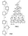
- FIG. 2 An arrangement for carrying out a Walsh-Hadamard transformation in this way is shown in FIG. 2. Every second signal of the signals supplied at the input 21 is temporarily stored in the buffer 24, so that two successive signal values are present at the input of the computing unit 22. In the Walsh-Hadamard transformation, the computing unit 22 forms the sum and the difference of these two values and outputs the results at the two outputs 23 and 25 designated accordingly. These initial values correspond to the coefficients F (0) and F (1) given in equation (3), which are given in FIG. 2.
- the first value of the output values at the output 23 is temporarily stored in the buffer memory 28 and then fed to the one input of the computing unit 26, while the second output value of the output 23 is fed directly to the other input of the computing unit 26.
- the corresponding process is carried out with the output values at the output 25, of which the first value is temporarily stored in the memory 32 and then fed in parallel to the computing unit 30 together with the respective second value.
- the computing unit 26 and 30 are constructed in exactly the same way as the computing unit 22 and also the following computing units 34, 38, 42 and 46.
- Output values then appear at the outputs of the computing units 26 and 30, which correspond to the coefficients of a sub-image consisting of 2x2 pixels. These output values are also alternately fed via the intermediate memories 36, 40, 44 or 48 or directly to the computing units 34, 38, 42 and 46. These computing units generate the coefficients F "(0), F" (1) ... of a sub-picture with 4x2 pixels at the outputs.
- This arrangement can be continued as desired that correspondingly large sub-images are transformed and the coefficient values are output in parallel.
- the arithmetic unit 22 since the arithmetic unit 22 only outputs two output signals in parallel for every second image signal supplied, and this applies to all subsequent arithmetic units, it may be expedient to temporarily store all the output signals of the arithmetic unit 22 for a sub-image of a predetermined size and, after processing all the image signals of this sub-image, the input of the arithmetic unit 22 switch to the output of this buffer and repeat this process for each stage according to the specified sub-picture size.
- a special control with a special address generator is necessary, but there is the advantage that only a single computing unit is required.
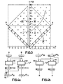
- the sloping coordinates A and B indicate the possible input values of an arithmetic unit.
- the Walsh-Hadamard coefficients F (0) and F (1) formed from this are given in the perpendicular coordinate system. From this it can be seen that the coefficients F (0) and F (1) each have a value range of 2 G if the value range of the signals A and B supplied is equal to G.
- the enlargement of the value range arises from the fact that a carry-over can occur when the sum is formed and a negative sign can occur when the difference is formed.
- the value combinations of the coefficients F (0) and F (1) indicated by crosses fulfill an uncertainty principle of the following form:
- This latter relationship describes the arrangement of the actually occurring combinations of values, denoted by crosses, of the two coefficients F (0) and F (1) in the form of a square standing on the top, so that the dashed outer square represents the total number of representable combinations of values includes, the areas in the corners are not occupied, so that the number of combinations of values that can be represented include a range that corresponds to a doubling of the range of actually occurring value combinations of the coefficients F (0) and F (1).
- FIG. 4a A circuit arrangement which realizes such a mapping of the coefficients and which can be used for each of the computing units 22, 26, 30 etc. in FIG. 2 is shown in FIG. 4a.
- the two signals A and B supplied are assumed to be four-bit dual words, which is indicated by the block with four boxes in the signal path. These two signals are fed to both an adding unit 60 and a subtracting unit 62, the subtracting unit 62 being supplied with a carry signal with the value "1" in order to obtain the corresponding difference representation in two's complement.
- the output values of the two units 60 and 62 represent the coefficients F (0) and F (1), which are represented by dual words with five bits. With the coefficient F (0), the bit Ü indicates the Instead of the highest value, the carry and for the coefficient F (1) the bit VZ at the position of the highest value, the sign.
- the reverse transformation unit 12 in FIG. 1 is constructed similarly to the transformation unit 2; when using the Walsh-Hadamard transformation, the two arrangements are even identical. Finally, by step-by-step processing of two coefficients, apart from the quantization errors, the original image data is generated. When using the modified coefficients that are generated by the arrangement according to FIG. 4a, however, a modified inverse transformation is also necessary.
- the values that are linked in the individual areas are shown in Table 1.
- the factor 1/2 for the total coefficient F * (0) results from the fact that the The least significant bit is omitted.
- the factor 1/2 also results from the fact that the least significant bit is separated and processed differently from the other bits, as subsequently based on a technical implementation in the form of a computing unit for performing the arithmetic operation described above is explained.
- Such a computing unit is shown in Fig. 4b.
- This also contains an adding unit 68 and a subtracting unit 66, to each of which two decoded coefficients or intermediate values are fed in parallel, of which the one coefficient, which is designated here with F * (0), was last created during the transformation from an addition and the other coefficient, which is designated here with F ** (1), was last created during the transformation from a subtraction.
- This latter coefficient is obtained from the coefficient F * (1) in that it has been extended by one bit in the most significant position, this additional bit having the value "0".
- each result value can also be interpreted as a modified coefficient of the next stage and in exactly the same way during the reverse transformation Be processed further. Exceeding the word length is thus avoided both during the transformation and during the reverse transformation, so that the computing units only have to be designed for the smallest possible word length. Furthermore, since the coefficients to be finally quantized have the same word length as that of the supplied image signals, there is a significant simplification and a better effectiveness of the quantization and thus also the data reduction.
- the first advantage arises from the fact that the quantizer only has to process positive values for the difference coefficient.
- the quantizer only has to process positive values for the difference coefficient.
- the number of reduced information units is essentially given by the fine-level quantization.
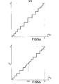
- the quantization curve according to Fig. 5a due to the required symmetry, an almost double-exact quantization in half of the original range is required, so that in this case there is only a small gain for data compression with a constant quantization error if this occurs with the corresponding quantization of the already mentioned characteristic curve symmetrical to the zero point is compared.
- the modified coefficients result in a gain of a factor of 2, since the same number of quantization stages is used only in half of the original range. This results in a profit with a factor between 1 and 2 for the modified coefficients.
- a second advantage results from the fact that, due to the symmetrical, non-linear quantization characteristic, large values of the difference coefficient are more precisely shown advertises so that even pronounced edge structures, ie steep transitions in the image, are better reproduced than with conventional methods.
- a Walsh-Hadamard transformation of a sub-image with four pixels A, B, C and D which can be carried out by applying the basic transformation twice according to equations (1) and (4). If the modified values according to Table 1 are formed each time the basic transformation is carried out, which does not result in an increase in the word length, the following four coefficients result:
- the sum coefficient F * (0) is in turn transmitted unchanged.
- the coefficient F * (1) it must be taken into account that in the first transformation step the most significant bit of the sums A + B or C + D representing the carry is changed by the equivalence function according to Table 1 and the bit of the lowest value is separated, what needs to be considered in the subsequent subtraction.
- the actual subtraction in the second transformation step then in turn requires a symmetrical characteristic curve according to FIG. 5a, so that the double-symmetrical characteristic curve shown in FIG. 5b is produced overall.
- the same quantization characteristic results for the coefficient F * (2).
- the coefficient F * (3) which arises from a two-fold difference formation, in turn only requires the single-symmetrical characteristic curve according to FIG. 5a.
- the formation of the modified coefficients results in a gain for the quantizer, since the quantizer only has to process coefficients with a value range equal to that of the original image signals.
- edge structures in the image are also better reproduced due to the symmetry of the quantization characteristic.
Landscapes
- Engineering & Computer Science (AREA)
- Multimedia (AREA)
- Signal Processing (AREA)
- Compression Or Coding Systems Of Tv Signals (AREA)
- Compression, Expansion, Code Conversion, And Decoders (AREA)
Abstract
Bei der üblichen Transformationskodierung von Bildern entsteht eine Vergrösserung der Wertebereiche der dabei erzeugten Koeffizienten bei der Durchführung der einzelnen Rechenschritte. Dadurch enthalten diese Koeffizienten eine erhebliche Redundanz, so dass die Wirksamkeit der Datenreduktion bei der anschliessenden Quantisierung vermindert wird. Erfindungsgemäss werden die auf der Grundtransformation von jeweils zwei Werten aufbauenden Rechenschritte so durchgeführt, dass sich als Ergebnis jedes Rechenschritts nur die ursprüngliche Wortlänge ergißt, indem bei jedem Rechenschritt ein Teil des Wertebereichs der Ergebnisse in einem anderen Bereich abgebildet wird. Es wiid ein Beispiel für die technische Durchführung einer solchen Abbildung auf modifizierte Koeffizienten und die Rücktransformation dieser modifizierten Koeffizienten beschrieben. Dabei müssen zweckmässig spezielle Quantisierungskennlinien angewendet werden, die noch zusätzliche Vorteile bringen.With the usual transformation coding of images, the value ranges of the coefficients generated thereby are enlarged when the individual calculation steps are carried out. As a result, these coefficients contain considerable redundancy, so that the effectiveness of the data reduction in the subsequent quantization is reduced. According to the invention, the calculation steps based on the basic transformation of two values are carried out in such a way that the result of each calculation step is only the original word length, in that a part of the value range of the results is mapped in a different area for each calculation step. An example for the technical implementation of such a mapping to modified coefficients and the inverse transformation of these modified coefficients has been described. In doing so, special quantization curves have to be used, which bring additional advantages.
Description
Die Erfindung betrifft eine Anordnung zum Speichern oder Übertragen und zum Rückgewinnen von Bildsignalen, bei der aus den durch punktweise Abtastung eines Bildes gewonnenen Bildsignalen in einer Transformationsanordnung transformierte Koeffizientenwerte gewonnen und diese in einem Quantisierer in quantisierte Werte umgewandelt werden und die quantisierten Werte nach Speicherung oder Übertragung in einem Dekodierer dekodiert und die dekodierten Werte in einer Rücktransformationsanordnung in Bildsignale zurückverwandelt werden, die den ursprünglichen Bildsignalen weitgehend entsprechen, wobei die Transformationsanordnung und die Rücktransformationsanordnung jeweils zwei Bildsignale bzw. dekodierte Werte entsprechend dem Transformations-Algorithmus zu zwei Ergebniswerten verknüpft und die Ergebniswerte verschiedener Verknüpfungen jeweils stufenweise weiter verknüpft.The invention relates to an arrangement for storing or transmitting and for recovering image signals, in which coefficient values transformed from the image signals obtained by point-by-point scanning of an image are obtained in a transformation arrangement and these are converted into quantized values in a quantizer and the quantized values after storage or transfer decoded in a decoder and the decoded values are converted back in a reverse transformation arrangement into image signals which largely correspond to the original image signals, the transformation arrangement and the reverse transformation arrangement each combining two image signals or decoded values according to the transformation algorithm to form two result values and the result values of different combinations linked step by step.
Für die Speicherung oder Übertragung von Bildern ist es gewünscht, möglichst wenige Informationseinheiten zu verwenden und dennoch das abgetastete Bild möglichst genau wieder darzustellen. Eine Verringerung der Anzahl Informationseinheiten ist möglich, wenn in einem Bild die vorhandene Redundanz und gegebenenfalls auch die Irrelevanz weitgehend beseitigt wird. Es ist bekannt, beispielsweise aus der Zeitschrift "IEEE Transactions on Computers", Vol. Com-19, Nr. 1, Februar 1971, Seiten 50 bis 62 oder aus dem Buch von Pratt "Digital Image Processing", John Wiley & Sons 1978, Seiten 232 bis 278, für diese Verringerung der Anzahl Informationseinheiten, d.h. für eine Datenkompression Transformationskodierverfahren mit nachfolgender Quantisierung zu verwenden. Bei der Quantisierung der Transformationskoeffizienten wird meist eine nichtlineare Kennlinie verwendet, die auf der Berechnung statistischer Mittelwerte beruht.For storing or transferring images, it is desirable to use as few information units as possible and still display the scanned image as accurately as possible. The number of information units can be reduced if the existing redundancy and possibly also the irrelevance are largely eliminated in an image. It is known, for example from the magazine "IEEE Transactions on Computers", Vol. Com-19, No. 1, February 1971, pages 50 to 62 or from the book by Pratt "Digital Image Processing", John Wiley & Sons 1978, Pages 232 to 278, for this reduction in the number of information units, ie for a data compression transform coding method with subsequent quantization. When quantizing The transformation coefficient is usually a non-linear characteristic curve that is based on the calculation of statistical averages.
Bei der Transformation von Bildsignalen tritt jedoch eine Vergrößerung des Wertebereiches der einzelnen transformierten Signale auf, wie kurz anhand einer Walsh-Hadamard-Transformation zweier Bildsignale A und B angedeutet werden soll. Die Transformation dieser beiden Bildpunkte liefert die beiden Koeffizienten![]()
![]()
![]()
![]()
Aufgabe der Erfindung ist es, eine Anordnung der eingangs genannten Art anzugeben, die eine Vergrößerung des Wertebereiches der zu speichernden oder der zu übertragenden Werte gegenüber dem ursprünglichen Wertebereich der Bildsignale vermeidet, wobei gleichzeitig eine günstige Quantisierung möglich ist. Diese Aufgabe wird erfindungsgemäß dadurch gelöst, daß die Transformationsanordnung mindestens ein zusätzliches Verknüpfungselement aufweist, das das Übertragsignal des bei jeder Verknüpfung entstehenden einen Ergebniswertes und das Vorzeichensignal des anderen Ergebniswertes erhält und am Ausgang ein Hilfssignal erzeugt, das dem einen Ergebniswert als höchstwertiges Bit zugeführt wird, wobei das Bit niedrigster Wertigkeit dieses Ergebniswertes sowie das Übertragsignal und das Vorzeichensignal der Ergebniswerte für die Speicherung oder Übertragung unterdrückt werden.The object of the invention is to provide an arrangement of the type mentioned at the outset which avoids an enlargement of the value range of the values to be stored or of the values to be transferred compared to the original value range of the image signals, at the same time being a favorable one Quantization is possible. This object is achieved according to the invention in that the transformation arrangement has at least one additional logic element which receives the carry signal of the one result value which arises with each logic operation and the sign signal of the other result value and generates an auxiliary signal at the output which is fed to the one result value as the most significant bit, the least significant bit of this result value and the carry signal and the sign signal of the result values being suppressed for storage or transmission.
Die Erfindung nutzt u.a. die Tatsache aus, daß die Ergebnisse der Summenbildung und der Differenzbildung von zwei Zahlen stets entweder beide gerade oder beide ungerade sein müssen, so daß das letzte Bit des einen der beiden Ergebniswerte weggelassen werden kann, ohne daß Information verloren geht. Auch die Verknüpfung von Übertrag und Vorzeichen der Ergebniswerte ergibt tatsächlich keine Mehrdeutigkeit, sondern die Ergebniswerte können bei der Rücktransformation eindeutig zurückgewandelt werden, wie später erläutert wird. Da auf diese Weise bei jeder Verknüpfung die Ergebniswerte nur denselben Wertebereich wie die verknüpften Werte aufweisen, haben also die zu quantisierenden Werte den gleichen Wertebereich wie die ursprünglichen Bildsignale. Das Entstehen einer durch die Transformation selbst erzeugten Redundanz wird somit vermieden, so daß zusammen mit einer Quantisierung eine optimale Datenkompression erreicht werden kann.The invention uses i.a. the fact that the results of summing and subtracting two numbers must always be both even or both odd so that the last bit of one of the two result values can be omitted without losing information. The combination of carry and sign of the result values does not actually result in any ambiguity, but the result values can be clearly converted back during the back transformation, as will be explained later. In this way, since the result values only have the same value range as the linked values for each link, the values to be quantized have the same value range as the original image signals. The occurrence of redundancy generated by the transformation itself is thus avoided, so that an optimal data compression can be achieved together with a quantization.
Bei manchen Transformations-Algorithmen, insbesondere bei der bereits genannten Walsh-Hadamard-Transformation, treten nur sehr einfache Verknüpfungen auf. Eine Ausgestaltung der Erfindung hierfür ist dadurch gekennzeichnet, daß die Transformationsanordnung die beiden Ergebniswerte jeder Verknüpfung aus der Summe und der Differenz zweier Werte bildet, daß das zusätzliche Verknüpfungselement ein Exklusiv-ODER-Glied ist und daß die Rücktransformationsanordnung jeweils einen ersten, das Bit niedrigster Wertigkeit noch enthaltenden dekodierten Wert mit einem zweiten, das Hilfssignal noch enthaltenden dekodierten Wert verknüpft und dabei die Bits des ersten Wertes um eine Stelle zur niedrigeren Wertigkeit verschiebt und der vorherigen Bitstelle höchster Wertigkeit den Wert "0" zuordnet und das Bit niedrigster Wertigkeit als Übertragsignal für die niedrigste Stelle bei der Summenbildung verarbeitet. Dabei ergibt sich also eine sehr einfache Ausbildung des zusätzlichen Verknüpfungselementes, das unabhängig von dem Wertebereich der Bildsignale ist, und auch bei der Rücktransformation werden die einzelnen Ergebniswerte auf einfache Weise gebildet, ohne daß der Übertrag und das Vorzeichen explizit rückgewandelt werden müssen.With some transformation algorithms, especially with the already mentioned Walsh-Hadamard transformation, only very simple links occur. An embodiment of the invention for this is characterized in that the transformation arrangement comprises the two result values of each combination of the sum and the difference between two values Forms that the additional logic element is an exclusive OR gate and that the reverse transformation arrangement each links a first decoded value containing the least significant bit with a second decoded value still containing the auxiliary signal and thereby the bits of the first value by one digit shifts to the lower value and assigns the value "0" to the previous bit position of highest value and processes the bit of the lowest value as a carry signal for the lowest position in the summation. This results in a very simple design of the additional linking element, which is independent of the value range of the image signals, and the individual result values are also formed in a simple manner during the back-transformation, without the carry-over and the sign having to be explicitly converted back.
Da die Verknüpfung von Übertrag und Vorzeichen der Ergebniswerte mathematisch gesehen eine andere Abbildung der Ergebniswerte im Darstellungsraum darstellt, muß zweckmäßigerweise auch die Kennlinie des Quantisierers bzw. des Dekodierers daran angepaßt werden. Eine weitere Ausgestaltung der Erfindung ist dafür dadurch gekennzeichnet, daß der Quantisierer nur in dem Wertebereich der ursprünglichen Bildsignale mit Quantisierungskennlinien arbeitet, die symmetrisch bzw. vielfach symmetrisch bezüglich in gleichem Abstand voneinander liegender Koeffizientenwerte sind. Dadurch ergibt sich gleichzeitig eine bessere Aufrechterhaltung von ausgeprägten Kantenstrukturen im Bild, wie ebenfalls später erläutert wird.Since the combination of the carry and the sign of the result values represents, mathematically speaking, another representation of the result values in the display space, the characteristic curve of the quantizer or decoder must expediently also be adapted to this. A further embodiment of the invention is characterized in that the quantizer works only in the value range of the original image signals with quantization characteristics which are symmetrical or, in many cases, symmetrical with respect to coefficient values that are equidistant from one another. This also results in better maintenance of pronounced edge structures in the image, as will also be explained later.
Ein Ausführungsbeispiel einer erfindungsgemäßen Anordnung wird nachstehend anhand der Zeichnung näher erläutert. Es zeigen
- Fig. 1 ein grobes Blockschaltbild einer gesamten Anordnung zur Transformation und Rücktransformation von Bildsignalen,
- Fig. 2 ein Blockschaltbild einer Transformationsanordnung oder Rücktransformationsanordnung,
- Fig. 3 schematisch die Abbildung von Teilen des Wertebereiches der Ergebniswerte auf einen anderen Wertebereich,
- Fig. 4a eine Anordnung zur Verknüpfung von zwei Werten sowie ein zusätzliches Verknüpfungselement zur Verwendung in der Transformationsanordnung,
- Fig. 4b eine Anordnung zur Verarbeitung von zwei transformierten Werten zur Verwendung in der Rücktransformationsanordnung,
- Fig. 5a und b zwei Quantisierkennlinien für zwei verschiedene Koeffizienten.
- 1 is a rough block diagram of an entire arrangement for transforming and re-transforming image signals,
- 2 shows a block diagram of a transformation arrangement or reverse transformation arrangement,
- 3 schematically shows the mapping of parts of the value range of the result values to another value range,
- 4a shows an arrangement for linking two values and an additional linking element for use in the transformation arrangement,
- 4b shows an arrangement for processing two transformed values for use in the reverse transformation arrangement,
- 5a and b two quantization curves for two different coefficients.
In Fig. 1 werden die Bildsignale über den Eingang 1 zugeführt. Diese Bildsignale können direkt vom Bildabtaster wie beispielsweise eine Fernsehaufnahmeeinrichtung geliefert werden, jedoch ist es allgemein zweckmäßiger, die Bildsignale eines Bildes in einem Speicher zwischenzuspeichern, da ein größeres Bild allgemein in aufeinanderfolgenden, meist quadratischen Unterbildern nacheinander transformiert und übertragen wird. Diese Möglichkeit ist jedoch nicht dargestellt, da sie für die Erfindung nicht von Belang ist.In Fig. 1, the image signals are supplied via the
Die über die Leitung 1 zugeführten Bildsignale werden in der Transformationsanordnung 2 entsprechend dem gewünschten Transformations-Algorithmus unter Steuerung der Steuereinheit 6 transformiert, und die transformierten Werte bzw. die Koeffizienten werden über die Leitung 3 dem Quantisierer 4 zugeführt, der ebenfalls von der Steuereinheit 6 gesteuert wird. Die quantisierten Werte werden der Übertragungsstrecke 10 zugeführt. Statt der Übertragungsstrecke kann insbesondere auch ein Speicher verwendet werden.The image signals supplied via
Die übertragenen bzw. aus dem Speicher ausgelesenen Werte werden auf der Empfangsseite einem Dekodierer 14 zugeführt, wo den einzelnen quantisierten Werten ein mittlerer Koeffizientenwert zugeordnet wird, der zu der durch diesen Wert angegebenen Quantisierungsstufe gehört. Die dekodierten Koeffizientenwerte werden über die Leitung 13 der Rücktransformationsanordnung 12 zugeführt, so daß am Ausgang 15 im wesentlichen die ursprünglichen, dem Eingang 1 zugeführten Bildsignale erscheinen.The values transmitted or read out from the memory are fed on the receiving side to a
Die Steuerung des Dekodierers 14 und der Rücktransformationsanordnung 12 erfolgt durch die Steuereinheit 16, die auch den Kennlinienspeicher für die Zuordnung von Eingangswerten zu Koeffizientenwerten in dem Dekodierer 14 enthält, ebenso wie die Steuereinheit 6 auf der Sendeseite den Kennlinienspeicher für den Quantisierer 4 enthält.The
Der allgemeine Aufbau einer Transformationsanordnung 2, eines Quantisierers 4, eines Dekodierers 14 und einer Rücktransformationsanordnung 12 ist grundsätzlich bekannt, wobei der Aufbau der Transformationsanordnungen auch bei einem gegebenen Transformations-Algorithmus unterschiedlich sein kann.The general structure of a
Für die weitere Erläuterung soll zunächst der mathematische Hintergrund angedeutet werden, und zwar anhand einer Walsh-Hadamard-Transformation. Als Grundschritt wird dabei eine 2 -Punkt-Transformation von jeweils zwei Bildpunkten A und B durchgeführt:

Die dabei entstehenden transformierten Signale bzw. Koeffizienten lauten ohne Normierung wie eingangs bereits angegeben
Diese Koeffizienten können also leicht mit Hilfe üblicher technischer Arithmetikbausteinen bestimmt werden, die nur für die Verarbeitung von jeweils zwei Werten aufgebaut sind.These coefficients can therefore easily be determined with the help of conventional technical arithmetic modules, which are only constructed for processing two values each.
Eine Walsh-Hadamard-Transformation für ein ganzes Bild bzw. Unterbild von 2n (n=2N, N=1,2, ...) Bildpunkten läßt sich schrittweise aus dem angegebenen Grundschritt in folgender Weise ableiten
Es werden also jeweils zwei aus verschiedenen Grundtransformationsschritten gebildete Koeffizienten mit einem solchen Grund-Transformationsschritt weiterverarbeitet usw., bis schließlich in jedem transformierten Signal alle Bildpunkte des genannten Bildes bzw. Unterbildes berücksichtigt sind. Die Transformation erfolgt also in mehreren Stufen. Es sind selbstverständlich auch Anordnungen denkparallel bar, bei denen die Matrizenmultiplikation quasi parallel durchgeführt wird, jedoch ist dafür ein außerordentlich großer Aufwand erforderlich, der sich nur bei ganz extremen Geschwindigkeitsanforderungen rechtfertigt. Die normalerweise praktisch durchgeführten Transformationen lassen sich dagegen stets auf die schrittweise Verarbeitung von jeweils zwei Werten zurückführen.Thus, two coefficients formed from different basic transformation steps are processed further with such a basic transformation step, etc., until finally all pixels of the named picture or sub-picture are taken into account in each transformed signal. The transformation therefore takes place in several stages. There are of course also arrangements parallel to the bar, in which the matrix multiplication is carried out quasi in parallel, but this requires an extraordinarily great effort, which is justified only with very extreme speed requirements. The transformations that are normally carried out in practice can always be traced back to the step-by-step processing of two values.
Eine Anordnung zu einer derartigen Durchführung einer Walsh-Hadamard-Transformation ist in Fig. 2 dargestellt. Von den am Eingang 21 zugeführten Signalen wird jedes zweite Signal im Zwischenspeicher 24 zwischengespeichert, so daß am Eingang der Recheneinheit 22 jeweils zwei aufeinanderfolgende Signalwerte anliegen. Die Recheneinheit 22 bildet bei der Walsh-Hadamard-Transformation jeweils die Summe und die Differenz dieser beiden Werte und gibt die Ergebnisse an den entsprechend bezeichneten beiden Ausgängen 23 und 25 ab. Diese Ausgangswerte entsprechen den in der Gleichung (3) angegebenen Koeffizienten F (0) und F (1), die in Fig. 2 angegeben sind.An arrangement for carrying out a Walsh-Hadamard transformation in this way is shown in FIG. 2. Every second signal of the signals supplied at the
Von den Ausgangswerten am Ausgang 23 wird jeweils der erste Wert im Zwischenspeicher 28 zwischengespeichert und dann dem einen Eingang der Recheneinheit 26 zugeführt, während der zweite Ausgangswert des Ausganges 23 dem anderen Eingang der Recheneinheit 26 direkt zugeführt wird. Der entsprechende Vorgang wird mit den Ausgangswerten am Ausgang 25 durchgeführt, von denen jeweils der erste Wert im Speicher 32 zwischengespeichert und dann zusammen mit dem jeweils zweiten Wert parallel der Recheneinheit 30 zugeführt wird. Die Recheneinheit 26 und 30 sind in völlig gleicher Weise aufgebaut wie die Recheneinheit 22 sowie auch die folgenden Recheneinheiten 34, 38, 42 und 46.The first value of the output values at the
An den Ausgängen der Recheneinheiten 26 und 30 erscheinen dann Ausgangswerte, die den Koeffizienten eines Unterbildes aus 2x2 Bildpunkten entsprechen. Auch diese Ausgangswerte werden abwechselnd über die Zwischenspeicher 36, 40, 44 oder 48 bzw. direkt den Recheneinheiten 34, 38, 42 und 46 zugeführt. Diese Recheneinheiten erzeugen an den Ausgängen die Koeffizienten F"(0), F"(1) ... eines Unterbildes mit 4x2 Bildpunkten.Output values then appear at the outputs of the
Diese Anordnung läßt sich beliebig weiter fortsetzen, so daß entsprechend große Unterbilder transformiert und die Koeffizientenwerte parallel abgegeben werden. Da die Recheneinheit 22 jedoch nur bei jedem zweiten zugeführten Bildsignal parallel zwei Ausgangssignale abgibt und dies für alle folgenden Recheneinheiten gilt, kann es zweckmäßig sein, alle Ausgangssignale der Recheneinheit 22 für ein Unterbild vorgegebener Größe zwischenzuspeichern und nach Verarbeitung aller Bildsignale dieses Unterbildes den Eingang der Recheneinheit 22 auf den Ausgang dieses Zwischenspeichers umzuschalten und diesen Vorgang für jede Stufe entsprechend der vorgegebenen Unterbildgröße zu wiederholen. Für eine solche, nach dem sogenannten "Pipeline-Prinzip" arbeitende Anordnung ist eine spezielle Steuerung mit einem besonderen Adressengenerator notwendig, jedoch ergibt sich der Vorteil, daß nur eine einzige Recheneinheit benötigt wird.This arrangement can be continued as desired that correspondingly large sub-images are transformed and the coefficient values are output in parallel. However, since the
Um zu vermeiden, daß in jeder Recheneinheit bzw. bei jeder Stufe der Verarbeitung eine Verdoppelung des Wertebereiches der Ausgangssignale gegenüber dem Wertebereich der Eingangssignale auftritt, wird nun eine andere Abbildung der Ergebniswerte vorgenommen, wie anhand der Fig. 3 erläutert werden soll. Die schrägliegenden Koordinaten A und B geben die möglichen Eingangswerte einer Recheneinheit an. Die daraus gebildeten Walsh-Hadamard-Koeffizienten F (0) und F (1) sind in dem senkrechtstehenden Koordinatensystem angegeben. Daraus ist zu ersehen, daß zunächst die Koeffizienten F (0) und F (1) je einen Wertebereich von 2 G aufweisen, wenn der Wertebereich der zugeführten Signale A und B gleich G ist. Die Vergrößerung des Wertebereiches entsteht dadurch, daß bei der Summenbildung ein Übertrag und bei der Differenzbildung ein negatives Vorzeichen auftreten kann. Andererseits ist aus Fig. 3 zu erkennen, daß die durch Kreuze angegebenen Wertekombinationen der Koeffizienten F (0) und F (1), die durch alle Kombinationen der Eingangswerte A und B gebildet werden, nicht alle möglichen Wertekombinationen der Koeffizienten innerhalb ihres gesamten Wertebereiches umfassen. Das bedeutet, daß die Koeffizienten in ihrer Darstellung eine durch die Transformation selbst erzeugte Redundanz enthalten. Diese wird nachfolgend näher bestimmt. Aus der Gleichung (3) folgt, daß die Koeffizienten F (0) und F (1) entweder beide gerade oder beide ungerade sind. Bei Dualdarstellung dieser Werte stimmen diese also stets in dem Bit niedrigster Wertigkeit überein, so daß dies nur von einem Koeffizienten berücksichtigt werden muß.In order to prevent the value range of the output signals from doubling in each computing unit or at each stage of the processing compared to the value range of the input signals, the result values are now mapped differently, as will be explained with reference to FIG. 3. The sloping coordinates A and B indicate the possible input values of an arithmetic unit. The Walsh-Hadamard coefficients F (0) and F (1) formed from this are given in the perpendicular coordinate system. From this it can be seen that the coefficients F (0) and F (1) each have a value range of 2 G if the value range of the signals A and B supplied is equal to G. The enlargement of the value range arises from the fact that a carry-over can occur when the sum is formed and a negative sign can occur when the difference is formed. On the other hand, it can be seen from FIG. 3 that the value combinations of the coefficients F (0) and F (1) indicated by crosses are formed by all combinations of the input values A and B. will not include all possible value combinations of the coefficients within their entire value range. This means that the coefficients contain redundancy generated by the transformation itself. This is determined in more detail below. From equation (3) it follows that the coefficients F (0) and F (1) are either both even or both are odd. When these values are represented in dual form, they always match in the least significant bit, so that only one coefficient has to take this into account.
Ferner ergibt sich aus Fig. 3, daß die durch Kreuze angegebenen Wertekombinationen der Koeffizienten F (0) und F (1) eine Unschärferelation der folgenden Form erfüllen:
Diese Einschränkung der Wertekombinationen der beiden Koeffizienten lassen sich nun dazu benutzen, transformierte Koeffizienten zu bilden, deren Wertebereich gegenüber dem der zugeführten Eingangswerte A und B nicht vergrößert ist. Dazu werden zumindest ein Teil der zunächst gebildeten Koeffizienten in einem anderen Bereich des in Fig. 3 dargestellten Ereignisfeldes abgebildet. Es sind verschiedene Abbildungen möglich.Jede dieser Abbildungen beruht auf einer Einteilung des ursprünglichen, in Fig. 3 dargestellten Ereignisfeldes in vier Bereiche I, II, III und IV, die durch den Übertrag des Summenkoeffizienten F (0) und durch das Vorzeichen des Differenzkoeffizienten F (1) bestimmt werden. Dabei wird davon ausgegangen, daß die Darstellung der Differenz A - B für den Differenzkoeffizienten F (1) im Zweierkomplement erfolgt:![]()
![]()
Dadurch werden positive Differenzen durch 1 Bit mit dem Wert "1" in der Stelle höchster Wertigkeit dargestellt, das als Vorzeichenbit VZ bezeichnet wird, und negative Differenzen enthalten den Wert "0" in der Bitstelle höchster Wertigkeit. Bei dem Summenkoeffizienten F (0) gibt die Bitstelle höchster Wertigkeit den Übertrag Ü an. Durch Verknüpfung des Übertragbits Ü und des Vorzeichenbits VZ der Koeffizienten F (0) und F (1) können verschiedene Abbildungen realisiert werden, so daß der gesamte darzustellende Wertebereich beider Koeffizienten zusammen halbiert wird. Durch zusätzliche Ausnutzung der ersten Bedingung, d.h. der Eigenschaft, daß nur beide Koeffizienten gerade oder ungerade sein können, ergeben sich modifizierte Koeffizienten, deren Wertebereich gleich dem der zugeführten Werte A und B ist. Bei einer solchen Abbildung entsteht kein Informationsverlust, so daß durch eine entsprechende Rücktransformation die Bildpunkte exakt rekonstruiert werden können.As a result, positive differences are represented by 1 bit with the value "1" in the most significant position, which is referred to as the sign bit VZ, and negative differences contain the value "0" in the most significant bit position. With the sum coefficient F (0), the bit position of the highest value indicates the carry Ü. By combining the carry bit Ü and the sign bit VZ of the coefficients F (0) and F (1), different mappings can be realized, so that the entire range of values of the two coefficients to be displayed is halved together. By additional use of the first condition, i.e. The property that only both coefficients can be even or odd results in modified coefficients whose value range is equal to that of the values A and B supplied. With such a mapping, there is no loss of information, so that the pixels can be reconstructed exactly by means of a corresponding reverse transformation.
In Fig. 3 ist ein Abbildungsverfahren angedeutet, bei dem der Bereich I nach rechts oberhalb des Bereiches IV und der Bereich III nach rechts unterhalb des Bereiches II verschoben ist. Die dadurch entstehenden modifizierten Koeffizienten F*(O) und F*(1) werden also entsprechend der nachstehenden Tabelle 1 gebildet, wobei für die Differenzbildung von der bereits angegebenen Darstellung im Zweierkomplement ausgegangen wird:

Dabei ist anders als in Fig. 3 hier von einer Anzahl G = 24 = 16 Werten der Eingangsvariablen A und B ausgegangen. Die Verschiebung ist also durch eine Exklusiv-NOR-Verknüpfung des Übertragbits Ü und des Vorzeichenbits VZ gebildet.In contrast to FIG. 3, a number G = 2 4 = 16 values of the input variables A and B is assumed here. The shift is thus formed by an exclusive NOR operation of the carry bit Ü and the sign bit VZ.
Eine Schaltungsanordnung, die eine solche Abbildung der Koeffizienten verwirklicht und die für jede der Recheneinheiten 22, 26, 30 usw. in Fig. 2 verwendet werden kann, ist in Fig. 4a dargestellt. Die beiden zugeführten Signale A und B werden als Vier-Bit-Dualworte angenommen, was durch den Block mit vier Kästchen im Signalweg angedeutet ist. Diese beiden Signale werden sowohl einer Addiereinheit 60 als auch einer Subtrahiereinheit 62 zugeführt, wobei der Subtrahiereinheit 62 ein Übertragsignal mit dem Wert "1" fest zugeführt wird, um die entsprechende Differenzdarstellung im Zweierkomplement zu erhalten. Die Ausgangswerte der beiden Einheiten 60 und 62 stellen die Koeffizienten F (0) und F (1) dar, die durch Dualworte mit fünf Bit dargestellt sind. Bei dem Koeffizienten F (0) gibt das Bit Ü an der Stelle höchster Wertigkeit den Übertrag und bei dem Koeffizienten F (1) das Bit VZ an der Stelle höchster Wertigkeit das Vorzeichen an.A circuit arrangement which realizes such a mapping of the coefficients and which can be used for each of the
Diese beiden Bits werden nun den Eingängen eines Exklusiv-NOR-Gatters bzw. Äquivalenz-Gatters 64 zugeführt, und das Ausgangssignal dieses Gatters ersetzt das Übertragbit Ü bei dem Koeffizienten F (0). Ferner wird das mit einem Kreuz versehene Bit niedrigster Wertigkeit dieses Koeffizienten weggelassen, da das entsprechende Bit des anderen Koeffizienten F (1) den gleichen Wert hat. Damit ist aer modifizierte Koeffizient F*(0) entstanden, der lediglich vier Bit lang ist, d.h. die gleiche Anzahl Informationseinheiten enthält wie die zugeführten Werte A und B. Beim Koeffizienten F (1) wird das Vorzeichenbit nicht weitergeführt, da es bereits indirekt in dem höchstwertigen Bit des modifizierten Koeffizienten F*(0) enthalten ist, sondern es werden nur die letzten vier Bits als modifizierter Koeffizient F*(1) weitergegeben. Damit hat auch dieser Koeffizient die gleiche Anzahl Informationseinheiten wie die zugeführten Werte A und B. Insgesamt entstehen damit die Koeffizienten F*(0) und F*(1) nach Tabelle 1, welche die gleiche Anzahl Informationseinheiten enthalten wie die zugeführten Werte A und B. Wenn also die Recheneinheiten 22, 26, 30 usw. in Fig. 2 durch eine Anordnung gemäß Fig. 4a verwirklicht werden, ist es klar, daß auch bei einer längeren Kaskadierung von Recheneinheiten für die Transformation eines größeren Unterbildes keine Vergrößerung der Wortlänge der Koeffizienten entsteht.These two bits are now fed to the inputs of an exclusive NOR gate or
Die Rücktransformationseinheit 12 in Fig. 1 ist ähnlich aufgebaut wie die Transformationseinheit 2, bei Verwendung der Walsh-Hadamard-Transformation sind die beiden Anordnungen sogar identisch. Es werden also ebenfalls durch schrittweise Verarbeitung jeweils zweier Koeffizienten schließlich wieder im wesentlichen, abgesehen von den Quantisierfehlern, die ursprünglichen Bilddaten erzeugt. Bei Verwendung der modifizierten Koeffizienten, die durch die Anordnung gemäß Fig. 4a erzeugt werden, ist allerdings auch eine modifizierte Rücktransformation erforderlich.The
Zunächst soll der mathematische Hintergrund der Rücktransformation der modifizierten Koeffizienten erläutert werden. Bei Verwendung der Walsh-Hadamard-Transformation wird wie erwähnt in gleicher Weise wie bei der Transformation jeweils die Summe und die Differenz zweier Koeffizienten bzw. bei den folgenden Schritten zweier Zwischenwerte gebildet. Unter Berücksichtigung der modifizierten Koeffizienten ergibt sich nun für die rücktransformierten Werte A und B, die hier also nicht unmittelbar die zurücktransformierten Bildsignale darstellen, sondern die Ergebniswerte bei jedem Zwischenschritt, die in der folgenden Tabelle 2 dargestellte Berechnung:

Die Werte, die dabei in den einzelnen Bereichen verknüpft werden, ergeben sich aus der Tabelle 1. Der Faktor 1/2 ergibt sich bei dem Summenkoeffizient F*(0) dadurch, daß das Bit niedrigster Wertigkeit weggelassen ist. Bei dem Differenzkoeffizienten F*(1) ergibt sich der Faktor 1/2 ebenfalls dadurch, daß das Bit niedrigster Wertigkeit abgetrennt und abweichend von den anderen Bits verarbeitet wird, wie anschließend anhand einer technischen Verwirklichung in Form einer Recheneinheit zur Durchführung der vorstehend beschriebenen arithmetischen Verknüpfung erläutert wird. Aus der Tabelle 2 ergibt sich, daß bei dieser Rücktransformation, bei der wieder die Subtraktion im Zweierkomplement durch Addition des Wertes 24 zur Differenz verwendet wird, die ursprünglichen Werte A und B unmittelbar zurückgewonnen werden, wobei lediglich bei Koeffizienten aus bestimmten Bereichen gemäß der Fig. 3 ein Übertrag in Form des Summanden 24 auftritt, der also durch Begrenzen der Ausgangswerte auf die letzten vier Bits der bei der Verarbeitung entstehenden Datenworte einfach eliminiert werden kann.The values that are linked in the individual areas are shown in Table 1. The
Eine derartige Recheneinheit ist in Fig. 4b dargestellt. Auch diese enthält wieder eine Addiereinheit 68 und eine Subtrahiereinheit 66, denen parallel jeweils zwei dekodierte Koeffizienten oder Zwischenwerte zugeführt werden, von denen der eine Koeffizient, der hier mit F*(0) bezeichnet ist, bei der Transformation zuletzt aus einer Addition entstanden ist und der andere Koeffizient, der hier mit F**(1) bezeichnet ist, bei der Transformation zuletzt aus einer Subtraktion entstanden ist. Dieser letztere Koeffizient ist aus dem Koeffizienten F*(1) dadurch en standen, daß dieser um ein Bit in der höchstwertigen Stelle verlängert worden ist, wobei dieses zusätzliche Bit den wert "0" hat. Von dem Koeffizienten F**(1) werden nun die vier höchstwertigen Bits gemeinsam mit den ler Bits des Koeffizienten F*(0) sowohl der Subtrahiereinheit 66 als auch der Addiereinheit 68 zugefükrt, wobei letztere als Übertragsignal das Bit niedrigster Wertigkeit des Koeffizienten F**(1) erhält, während die Subtrahiereinheit 66 als Übertragsignal ständig ein Signal mit dem Wert "1" erhält. Es könnte zunächst angenommen werden, daß das Bit niedrigster Wertigkeit des modifizierten Koeffizienten F**(1)auch dem modifizierten Koeffizienten F*(0) wieder zugeführt werden müßte. Da dann aber bei der Addition in der letzten Stelle zwei wertgleiche Bits addiert werden, würde ein Übertrag auftreten, wenn diese den Wert "1" haben. Aus diesem Grunde wird dieses Bit daher nur als Übertragsignal der Addiereinheit 68 zugeführt. Für die Subtrahiereinheit 66 ist dagegen der Wert dieses Bits ohne Bedeutung und wird dort nicht verarbeitet.Such a computing unit is shown in Fig. 4b. This also contains an adding
Von den Ausgangssignalen der Einheiten 66 und 68 wird das höchstwertige Bit, das einen Übertrag enthalten kann, abgetrennt und nicht weiterverarbeitet, da die vier unteren Bits unmittelbar den gesuchten Wert angeben, wie anhand der Tabelle 2 bereits erläutert wurde. Auf diese Weise ist es also möglich, auch bei der Rücktransformation eine Vergrößerung der Wortbreite zu vermeiden, wobei die beiden Einheiten 66 und 68 jeweils nur die Anzahl Bits verarbeiten müssen, die auch die zugeführten modifizierten Koeffizienten enthalten.The most significant bit, which can contain a carry, is separated from the output signals of
Da eine vollständige Walsh-Hadamard-Transformation auf einer größeren Anzahl von Bildpunkten entsprechend Gleichung (4) schrittweise aus der 2-Punkt-Transformation abgeleitet werden kann, kann auch bei der Rücktransformation jeder Ergebniswert wieder als modifizierter Koeffizient der nächsten Stufe aufgefaßt und in genau gleicher Weise weiterverarbeitet werden. Damit wird sowohl bei der Transformation als auch bei der Rücktransformation ein Überschreiten der Wortlänge vermieden, so daß die Recheneinheiten jeweils nur für die geringstmögliche Wortlänge ausgelegt sein müssen. Weiterhin ergibt sich, da die endgültig zu quantisierenden Koeffizienten die gleiche Wortlänge haben wie die der zugeführten Bildsignale, eine wesentliche Vereinfachung und eine bessere Wirksamkeit der Quantisierung und damit auch der Datenreduktion.Since a complete Walsh-Hadamard transformation on a larger number of pixels can be derived step by step from the 2-point transformation according to equation (4), each result value can also be interpreted as a modified coefficient of the next stage and in exactly the same way during the reverse transformation Be processed further. Exceeding the word length is thus avoided both during the transformation and during the reverse transformation, so that the computing units only have to be designed for the smallest possible word length. Furthermore, since the coefficients to be finally quantized have the same word length as that of the supplied image signals, there is a significant simplification and a better effectiveness of the quantization and thus also the data reduction.
Darüber hinaus entsteht auch noch ein zusätzlicher Gewinn bei der Quantisierung, wodurch mit vergleichbarem Aufwand eine genauere Darstellung der quantisierten Werte erreicht werden kann. Durch Quantisierungskennlinien, die dem entwickelten Verfahren speziell angepaßt sind, werden auch große Werte der Transformationskoeffizienten jeder einzelnen Transformationsstufe genau dargestellt, so daß auch ausgeprägte Kantenstrukturen im Bild besser wiedergegeben werden. als bei herkömmlichen Verfahren. Dies soll nachstehend anhand von zwei Beispielen näher erläutert werden.In addition, there is also an additional gain in the quantization, as a result of which a more precise representation of the quantized values can be achieved with comparable effort. Large values of the transformation coefficients of each individual transformation stage are precisely represented by quantization characteristics, which are specially adapted to the developed method, so that even pronounced edge structures are better reproduced in the image. than with conventional methods. This will be explained in more detail below using two examples.
Zunächst sei eine 2-Punkt-Grundtransformation der beiden Bildpunkte A und B betrachtet, die je einen aus einer Anzahl G Werte annehmen können. Diese Transformation führt zu den in Gleichung (3) angegebenen beiden Koeffizienten F (0) und F (1). Bei den bisher üblichen Verfahren wird der Summenkoeffizient F (0) unverändert übertragen, während der Differenzkoeffizient F (1), der also auch negative Werte annehmen kann, zur Datenkompression durch eine nichtlineare, zum Nullpunkt symmetrische Kennlinie quantisiert und anschließend mittels einer geringeren Anzahl von Informationseinheiten übertragen bzw. gespeichert wird. Die Nichtlinearität wird so gewählt, daß häufig auftretende kleine Differenzen fein quantisiert werden, während weniger häufig auftretende große Differenzwerte entsprechend gröber quantisiert werden.First, consider a 2-point basic transformation of the two pixels A and B, which can each take one of a number G values. This transformation leads to the two coefficients F (0) and F (1) given in equation (3). In the previously common methods, the sum coefficient F (0) is transmitted unchanged, while the difference coefficient F (1), which can also take negative values, is quantized for data compression by a nonlinear characteristic curve that is symmetrical to the zero point and then by means of a smaller number of information units is transferred or saved. The non-linearity is chosen so that frequently occurring small differences are finely quantized, while less frequently occurring large difference values are correspondingly coarser.
Bei der Verwendung der beschriebenen modifizierten Koeffizienten wird dagegen das Vorzeichen des Differenzkoeffizienten F (1) abgetrennt und nicht übertragen. Durch die Streichung des Vorzeichens ergibt sich bei der Differenzbildung durch die Darstellung im Zweierkomplement die folgende Abbildung:
- Kleine negative Differenzen ergeben große positive Differenzen, große negative Differenzen ergeben kleine positive Differenzen.
- Small negative differences result in large positive differences, large negative differences result in small positive differences.
Die Bedingung, daß kleine positive Differenzen sowie kleine negative Differenzen wegen ihrer größeren Auftrittswahrscheinlichkeit in feinen Stufen quantisiert werden müssen, führt zu einer symmetrischen Quantisierungskennlinie, die in Fig. 5a dargestellt ist. Diese Quantisierungskennlinie ergibt außerdem noch einige zusätzliche Vorteile.The condition that small positive differences as well as small negative differences have to be quantized in fine steps because of their greater probability of occurrence leads to a symmetrical quantization characteristic curve, which is shown in FIG. 5a. This quantization curve also gives some additional advantages.
Der erste Vorteil entsteht daraus, daß der Quantisierer bei dem Differenzkoeffizienten nur positive Werte verarbeiten muß. Bei Verwendung einer stark nichtlinearen Quantisierung mit einer sehr feinstufigen Quantisierung im Bereich betragsmäßig kleiner Differenzen ist die Anzahl der reduzierten Informationseinheiten im wesentlichen durch die feinstufige Quantisierung gegeben. Für die Quantisierungskennlinie nach Fig. 5a ist dann durch die erforderliche Symmetrie eine allerdings nur fast doppelt genaue Quantisierung in der Hälfte des ursprünglichen Bereiches erforderlich, so daß sich in diesem Falle nur an geringer Gewinn für die Datenkompression bei gleichbleibendem Quantisierungsfehler ergibt, wenn dieses mit der entsprechenden Quantisierung der bereits genannten, zum Nullpunkt symmetrischen Kennlinie üblicher Art verglichen wird. Im anderen Fall einer linearen Quantisierung ergibt sich für die modifizierten Koeffizienten jedoch ein Gewinn mit dem Faktor 2, da die gleiche Stufenzahl der Quantisierung nur in der Hälfte des ursprünglichen Bereiches verwendet wird. Damit ergibt sich für die modifizierten Koeffizienten ein Gewinn mit einem Faktor zwischen 1 und 2.The first advantage arises from the fact that the quantizer only has to process positive values for the difference coefficient. When using a strongly non-linear quantization with a very fine-level quantization in the range of small differences in terms of amount, the number of reduced information units is essentially given by the fine-level quantization. For the quantization curve according to Fig. 5a, however, due to the required symmetry, an almost double-exact quantization in half of the original range is required, so that in this case there is only a small gain for data compression with a constant quantization error if this occurs with the corresponding quantization of the already mentioned characteristic curve symmetrical to the zero point is compared. In the other case of linear quantization, however, the modified coefficients result in a gain of a factor of 2, since the same number of quantization stages is used only in half of the original range. This results in a profit with a factor between 1 and 2 for the modified coefficients.
Ein zweiter Vorteil ergibt sich daraus, daß aufgrund der symmetrischen nichtlinearen Quantisierungskennlinie betragsmäßig große Werte des Differenzkoeffizienten genauer dargestellt werben, so daß auch ausgeprägte Kantenstrukturen, d.h. steile bergänge im Bild besser wiedergegeben werden als bei herkömmlichen Verfahren. Als zweites Beispiel sei eine Walsh-Hadamard-Transformation eines Unterbildes mit vier Bildpunkten A, B, C und D betrachtet, die durch zweimalige Anwendung der Grundtransformation gemäß Gleichung (1) und (4) durchgeführt werden kann. Wenn bei jeder Ausführung der Grundtransformation die modifizierten Werte gemäß der Tabelle 1 gebildet werden, wodurch keine Vergrößerung der Wortlänge entsteht, ergeben sich die folgenden vier Koeffizienten:![]()
![]()
![]()
![]()
![]()
![]()
![]()
![]()
Der Summenkoeffizient F*(0) wird wiederum unverändert übertragen. Bei dem Koeffizienten F*(1) ist zu berücksichtigen, daß bei dem ersten Transformationsschritt das den Übertrag darstellende höchstwertige Bit der Summen A + B bzw. C + D durch die Äquivalenz-Funktion nach Tabelle 1 verändert und das Bit niedrigster Wertigkeit abgetrennt wird, was bei der anschließenden Subtraktion zu berücksichtigen ist. Die eigentliche Subtraktion im zweiten Transformationsschritt erfordert dann wiederum eine symmetrische Kennlinie nach Fig. 5a, so daß insgesamt die in Fig. 5b dargestellte doppelt symmetrische Kennlinie entsteht. Die gleiche Quantisierungscharakteristik ergibt sich für den Koeffizienten F*(2). Der Koeffizient F*(3), der durch eine zweimalige Differenzbildung entsteht, benötigt wiederum nur die einfach symmetrische Kennlinie gemäß Fig. 5a. Auch in diesem Beispiel ergibt sich durch die Bildung der modifizierten Koeffizienten für den Quantisierer ein Gewinn, da dieser nur Koeffizienten mit einem Wertebereich gleich dem der ursprünglichen Bildsignale verarbeiten muß. Zusätzlich werden durch die Symmetrie der Quantisierungskennlinie auch ausgeprägte Kantenstrukturen im Bild besser wiedergegeben.The sum coefficient F * (0) is in turn transmitted unchanged. With the coefficient F * (1) it must be taken into account that in the first transformation step the most significant bit of the sums A + B or C + D representing the carry is changed by the equivalence function according to Table 1 and the bit of the lowest value is separated, what needs to be considered in the subsequent subtraction. The actual subtraction in the second transformation step then in turn requires a symmetrical characteristic curve according to FIG. 5a, so that the double-symmetrical characteristic curve shown in FIG. 5b is produced overall. The same quantization characteristic results for the coefficient F * (2). The coefficient F * (3), which arises from a two-fold difference formation, in turn only requires the single-symmetrical characteristic curve according to FIG. 5a. In this example too, the formation of the modified coefficients results in a gain for the quantizer, since the quantizer only has to process coefficients with a value range equal to that of the original image signals. In addition pronounced edge structures in the image are also better reproduced due to the symmetry of the quantization characteristic.
Dies gilt auch für die Transformation von größeren Unterbildern mit entsprechend mehr Bildpunkten, die entsprechend mehr Stufen mit der Durchführung der Grundtransformation erfordert. Die dabei entstehenden Koeffizienten werden dann mittels symmetrischer bzw. vielfachsymmetrischer nichtlinearer Quantisierungskennlinien quantisiert, die entsprechend den beiden beschriebenen Beispielen der Folge der einzelnen Transformationsschritte nach Tabelle 1 anzupassen sind.This also applies to the transformation of larger sub-images with correspondingly more pixels, which requires correspondingly more stages with the implementation of the basic transformation. The resulting coefficients are then quantized by means of symmetrical or multiple-symmetrical nonlinear quantization characteristics, which are to be adapted in accordance with the two examples described to the sequence of the individual transformation steps according to Table 1.
Claims (3)
Applications Claiming Priority (2)
| Application Number | Priority Date | Filing Date | Title |
|---|---|---|---|
| DE3138816 | 1981-09-30 | ||
| DE19813138816 DE3138816A1 (en) | 1981-09-30 | 1981-09-30 | ARRANGEMENT FOR STORING OR TRANSMITTING AND RECOVERY OF IMAGE SIGNALS |
Publications (3)
| Publication Number | Publication Date |
|---|---|
| EP0077089A2 true EP0077089A2 (en) | 1983-04-20 |
| EP0077089A3 EP0077089A3 (en) | 1986-06-04 |
| EP0077089B1 EP0077089B1 (en) | 1988-09-07 |
Family
ID=6142984
Family Applications (1)
| Application Number | Title | Priority Date | Filing Date |
|---|---|---|---|
| EP82201199A Expired EP0077089B1 (en) | 1981-09-30 | 1982-09-24 | Device for storing or transmitting transform-coded picture signals and for regaining those picture signals |
Country Status (4)
| Country | Link |
|---|---|
| US (1) | US4463377A (en) |
| EP (1) | EP0077089B1 (en) |
| JP (1) | JPS5871768A (en) |
| DE (2) | DE3138816A1 (en) |
Cited By (3)
| Publication number | Priority date | Publication date | Assignee | Title |
|---|---|---|---|---|
| EP0118754A2 (en) * | 1983-02-11 | 1984-09-19 | Siemens Aktiengesellschaft | Method and cicuit for digitally transmitting television pictures |
| EP0237928A2 (en) * | 1986-03-18 | 1987-09-23 | Deutsche Thomson-Brandt GmbH | Method for correcting blockwise transmitted discrete values |
| US5805293A (en) * | 1995-01-30 | 1998-09-08 | Nec Corporation | Hadamard transform coding/decoding method and apparatus for image signals |
Families Citing this family (12)
| Publication number | Priority date | Publication date | Assignee | Title |
|---|---|---|---|---|
| NL8105799A (en) * | 1981-12-23 | 1983-07-18 | Philips Nv | SYSTEM FOR THE TRANSFER OF A TELEVISION IMAGE INFORMATION BY AN ERROR-PROTECTIVE CODE, IMAGER WITH DEVICE FOR GENERATING SUCH A PROTECTIVE CODE, AND THE DISPLAYING COVERING THE COATING OF THE COURTICTION IN THE COURSE OF THE COURTICLE. |
| US4621337A (en) * | 1983-08-11 | 1986-11-04 | Eastman Kodak Company | Transformation circuit for implementing a collapsed Walsh-Hadamard transform |
| US4673988A (en) * | 1985-04-22 | 1987-06-16 | E.I. Du Pont De Nemours And Company | Electronic mosaic imaging process |
| DE3728444A1 (en) * | 1987-08-26 | 1989-03-09 | Thomson Brandt Gmbh | METHOD AND CIRCUIT FOR IMPROVING THE RESOLUTION OF DIGITAL SIGNALS |
| TW224553B (en) * | 1993-03-01 | 1994-06-01 | Sony Co Ltd | Method and apparatus for inverse discrete consine transform and coding/decoding of moving picture |
| US5412429A (en) * | 1993-03-11 | 1995-05-02 | The United States Of America As Represented By The Administrator Of The National Aeronautics And Space Administration | Picture data compression coder using subband/transform coding with a Lempel-Ziv-based coder |
| DE4423226C1 (en) * | 1994-07-01 | 1995-08-24 | Harris Corp | Digital decoding composite video, blanking and synchronisation signals |
| JP3058028B2 (en) * | 1994-10-31 | 2000-07-04 | 三菱電機株式会社 | Image encoded data re-encoding device |
| US5856935A (en) * | 1996-05-08 | 1999-01-05 | Motorola, Inc. | Fast hadamard transform within a code division, multiple access communication system |
| US7200629B2 (en) * | 2002-01-04 | 2007-04-03 | Infineon Technologies Ag | Apparatus and method for Fast Hadamard Transforms |
| US9008184B2 (en) | 2012-01-20 | 2015-04-14 | Blackberry Limited | Multiple sign bit hiding within a transform unit |
| US9450601B1 (en) * | 2015-04-02 | 2016-09-20 | Microsoft Technology Licensing, Llc | Continuous rounding of differing bit lengths |
Citations (6)
| Publication number | Priority date | Publication date | Assignee | Title |
|---|---|---|---|---|
| US3775602A (en) * | 1972-06-29 | 1973-11-27 | Us Air Force | Real time walsh-hadamard transformation of two-dimensional discrete pictures |
| US3956619A (en) * | 1975-03-31 | 1976-05-11 | General Electric Company | Pipeline walsh-hadamard transformations |
| US3981443A (en) * | 1975-09-10 | 1976-09-21 | Northrop Corporation | Class of transform digital processors for compression of multidimensional data |
| US3988605A (en) * | 1974-02-25 | 1976-10-26 | Etat Francais | Processors for the fast transformation of data |
| US4134134A (en) * | 1976-06-10 | 1979-01-09 | U.S. Philips Corporation | Apparatus for picture processing |
| US4261043A (en) * | 1979-08-24 | 1981-04-07 | Northrop Corporation | Coefficient extrapolator for the Haar, Walsh, and Hadamard domains |
Family Cites Families (2)
| Publication number | Priority date | Publication date | Assignee | Title |
|---|---|---|---|---|
| JPS5515147B2 (en) * | 1974-05-02 | 1980-04-21 | ||
| US4055756A (en) * | 1975-02-03 | 1977-10-25 | Societe Anonyme De Telecommunications | Image coder-decoder using a matrix transform with weighted contribution of several points of the image to the formation of one point of the transform |
-
1981
- 1981-09-30 DE DE19813138816 patent/DE3138816A1/en not_active Withdrawn
-
1982
- 1982-09-22 US US06/421,610 patent/US4463377A/en not_active Expired - Fee Related
- 1982-09-24 DE DE8282201199T patent/DE3279023D1/en not_active Expired
- 1982-09-24 EP EP82201199A patent/EP0077089B1/en not_active Expired
- 1982-09-30 JP JP57169946A patent/JPS5871768A/en active Granted
Patent Citations (6)
| Publication number | Priority date | Publication date | Assignee | Title |
|---|---|---|---|---|
| US3775602A (en) * | 1972-06-29 | 1973-11-27 | Us Air Force | Real time walsh-hadamard transformation of two-dimensional discrete pictures |
| US3988605A (en) * | 1974-02-25 | 1976-10-26 | Etat Francais | Processors for the fast transformation of data |
| US3956619A (en) * | 1975-03-31 | 1976-05-11 | General Electric Company | Pipeline walsh-hadamard transformations |
| US3981443A (en) * | 1975-09-10 | 1976-09-21 | Northrop Corporation | Class of transform digital processors for compression of multidimensional data |
| US4134134A (en) * | 1976-06-10 | 1979-01-09 | U.S. Philips Corporation | Apparatus for picture processing |
| US4261043A (en) * | 1979-08-24 | 1981-04-07 | Northrop Corporation | Coefficient extrapolator for the Haar, Walsh, and Hadamard domains |
Non-Patent Citations (1)
| Title |
|---|
| PROCEEDINGS OF THE IEEE 1979 NATIONAL AEROSPACE AND ELECTRONICS CONFERENCE NAECON 1979, Band 3, 15.-17. Mai 1979, Dayton, US, Seiten 1218-1231, IEEE, New York, US; D.J. SPENCER et al.: "A real time video bandwidth reduction system based on a CCD hadamard transform device" * |
Cited By (5)
| Publication number | Priority date | Publication date | Assignee | Title |
|---|---|---|---|---|
| EP0118754A2 (en) * | 1983-02-11 | 1984-09-19 | Siemens Aktiengesellschaft | Method and cicuit for digitally transmitting television pictures |
| EP0118754A3 (en) * | 1983-02-11 | 1985-11-13 | Siemens Aktiengesellschaft | Method of digitally transmitting television pictures |
| EP0237928A2 (en) * | 1986-03-18 | 1987-09-23 | Deutsche Thomson-Brandt GmbH | Method for correcting blockwise transmitted discrete values |
| EP0237928A3 (en) * | 1986-03-18 | 1989-03-29 | Deutsche Thomson-Brandt Gmbh | Method for correcting blockwise transmitted discrete values |
| US5805293A (en) * | 1995-01-30 | 1998-09-08 | Nec Corporation | Hadamard transform coding/decoding method and apparatus for image signals |
Also Published As
| Publication number | Publication date |
|---|---|
| US4463377A (en) | 1984-07-31 |
| EP0077089A3 (en) | 1986-06-04 |
| JPH0262993B2 (en) | 1990-12-27 |
| DE3138816A1 (en) | 1983-04-14 |
| JPS5871768A (en) | 1983-04-28 |
| DE3279023D1 (en) | 1988-10-13 |
| EP0077089B1 (en) | 1988-09-07 |
Similar Documents
| Publication | Publication Date | Title |
|---|---|---|
| DE2640140C2 (en) | Method and arrangement for redundancy-reducing image coding | |
| EP0077089B1 (en) | Device for storing or transmitting transform-coded picture signals and for regaining those picture signals | |
| DE2625973C3 (en) | Method and arrangement for the redundancy-reducing transformation of images | |
| DE2640157C2 (en) | Method and arrangement for redundancy-reducing coding of pictures | |
| DE4239126A1 (en) | ||
| DE3331426A1 (en) | ARRANGEMENT FOR TWO-DIMENSIONAL DPCM CODING | |
| DE3708288A1 (en) | Method for reducing the amount of data for image coding | |
| EP0742673A2 (en) | Method for image data reduction by fractal image encoding with encoder and decoder for carrying out said method | |
| EP0304836A2 (en) | Method and circuit concerning the resolution of digital signals | |
| DE3545106C2 (en) | ||
| DE3424078A1 (en) | DECIMAL MULTIPLICATION DEVICE | |
| DE3335386A1 (en) | CIRCUIT FOR CSD CODING A BINARY NUMBER SHOWN IN TWO COMPLEMENT | |
| EP1110407B1 (en) | Method and array for coding and decoding a digitized image using an overall motion vector | |
| EP0148528B1 (en) | Method and circuit for increasing the resolution of a digital time-dependent signal | |
| DE3417262C2 (en) | ||
| EP0346750B1 (en) | Device for dpcm coding at a high data rate | |
| DE4212003A1 (en) | DEVICE FOR READING A PROBABILITY ASSESSMENT CHART | |
| EP1034511B1 (en) | Method for converting digital raster data of a first resolution into digital target data of a second resolution | |
| DE3124550C2 (en) | ||
| DE3726601C2 (en) | ||
| EP0264999A2 (en) | System for transmitting or memorizing input signals | |
| EP0303978B1 (en) | Method and circuit for enhancing the resolution of digital signals | |
| DE3832476C2 (en) | ||
| EP0241745A1 (en) | Method for the data reduction of digital picture signals by vector quantization of coefficients obtained by orthonormal transformation by means of a symmetrical, nearly cyclical Hadamard matrix | |
| DE4128977A1 (en) | Video signal filter circuit for transformed and quantised data blocks - uses two=dimensional block coordinates with relative coordinates or transformation coefficients with two=dimensional variables |
Legal Events
| Date | Code | Title | Description |
|---|---|---|---|
| PUAI | Public reference made under article 153(3) epc to a published international application that has entered the european phase |
Free format text: ORIGINAL CODE: 0009012 |
|
| 17P | Request for examination filed |
Effective date: 19820924 |
|
| AK | Designated contracting states |
Designated state(s): DE FR GB |
|
| PUAL | Search report despatched |
Free format text: ORIGINAL CODE: 0009013 |
|
| AK | Designated contracting states |
Kind code of ref document: A3 Designated state(s): DE FR GB |
|
| RAP1 | Party data changed (applicant data changed or rights of an application transferred) |
Owner name: N.V. PHILIPS' GLOEILAMPENFABRIEKEN Owner name: PHILIPS PATENTVERWALTUNG GMBH |
|
| 17Q | First examination report despatched |
Effective date: 19871111 |
|
| GRAA | (expected) grant |
Free format text: ORIGINAL CODE: 0009210 |
|
| AK | Designated contracting states |
Kind code of ref document: B1 Designated state(s): DE FR GB |
|
| REF | Corresponds to: |
Ref document number: 3279023 Country of ref document: DE Date of ref document: 19881013 |
|
| ET | Fr: translation filed | ||
| GBT | Gb: translation of ep patent filed (gb section 77(6)(a)/1977) | ||
| PLBE | No opposition filed within time limit |
Free format text: ORIGINAL CODE: 0009261 |
|
| STAA | Information on the status of an ep patent application or granted ep patent |
Free format text: STATUS: NO OPPOSITION FILED WITHIN TIME LIMIT |
|
| 26N | No opposition filed | ||
| PGFP | Annual fee paid to national office [announced via postgrant information from national office to epo] |
Ref country code: DE Payment date: 19891129 Year of fee payment: 8 |
|
| PGFP | Annual fee paid to national office [announced via postgrant information from national office to epo] |
Ref country code: GB Payment date: 19900831 Year of fee payment: 9 |
|
| PGFP | Annual fee paid to national office [announced via postgrant information from national office to epo] |
Ref country code: FR Payment date: 19900920 Year of fee payment: 9 |
|
| PG25 | Lapsed in a contracting state [announced via postgrant information from national office to epo] |
Ref country code: DE Effective date: 19910601 |
|
| PG25 | Lapsed in a contracting state [announced via postgrant information from national office to epo] |
Ref country code: GB Effective date: 19910924 |
|
| GBPC | Gb: european patent ceased through non-payment of renewal fee | ||
| PG25 | Lapsed in a contracting state [announced via postgrant information from national office to epo] |
Ref country code: FR Effective date: 19920529 |
|
| REG | Reference to a national code |
Ref country code: FR Ref legal event code: ST |