EP0241352A1 - Circuit for performing a linear transformation on a digital signal - Google Patents
Circuit for performing a linear transformation on a digital signal Download PDFInfo
- Publication number
- EP0241352A1 EP0241352A1 EP87400707A EP87400707A EP0241352A1 EP 0241352 A1 EP0241352 A1 EP 0241352A1 EP 87400707 A EP87400707 A EP 87400707A EP 87400707 A EP87400707 A EP 87400707A EP 0241352 A1 EP0241352 A1 EP 0241352A1
- Authority
- EP
- European Patent Office
- Prior art keywords
- circuit
- branch
- graph
- node
- multiplier
- Prior art date
- Legal status (The legal status is an assumption and is not a legal conclusion. Google has not performed a legal analysis and makes no representation as to the accuracy of the status listed.)
- Withdrawn
Links
Images


Classifications
-
- G—PHYSICS
- G06—COMPUTING; CALCULATING OR COUNTING
- G06F—ELECTRIC DIGITAL DATA PROCESSING
- G06F17/00—Digital computing or data processing equipment or methods, specially adapted for specific functions
- G06F17/10—Complex mathematical operations
- G06F17/14—Fourier, Walsh or analogous domain transformations, e.g. Laplace, Hilbert, Karhunen-Loeve, transforms
- G06F17/147—Discrete orthonormal transforms, e.g. discrete cosine transform, discrete sine transform, and variations therefrom, e.g. modified discrete cosine transform, integer transforms approximating the discrete cosine transform
-
- G—PHYSICS
- G06—COMPUTING; CALCULATING OR COUNTING
- G06F—ELECTRIC DIGITAL DATA PROCESSING
- G06F17/00—Digital computing or data processing equipment or methods, specially adapted for specific functions
- G06F17/10—Complex mathematical operations
- G06F17/14—Fourier, Walsh or analogous domain transformations, e.g. Laplace, Hilbert, Karhunen-Loeve, transforms
- G06F17/141—Discrete Fourier transforms
- G06F17/142—Fast Fourier transforms, e.g. using a Cooley-Tukey type algorithm
Definitions
- the present invention relates to a circuit for performing a linear transformation on a digital signal composed of N digital samples, where N is an integer.
- the invention finds an application in particular in the processing of digital signals, for example image or speech signals, with a view to coding these signals before their transmission on a transmission line.
- linear transformation such as for example the discrete Fourier transform, the discrete cosine transform, the discrete sine transform, the discrete Hadamard transform, or others. These transforms are said to be “discrete” with reference to the digital nature of the processed signal.
- the linear transformation applied to a digital signal of N samples is conventionally represented by a graph in which the branches represent an operation of multiplication and the nodes an operation of addition or subtraction.
- multipliers are the costly elements of the circuit, both in terms of their price, their surface area or their consumption.
- the number of multipliers is therefore reduced to the maximum by assigning to each multiplier the calculations of several branches of the graph, so as to obtain a maximum utilization rate of each of these multipliers.
- Two types of circuit are known for carrying out a linear transformation, in particular a discrete cosine transformation or a discrete Fourier transformation.
- a first known architecture consists in using a large number of signal processing microprocessors working in parallel.
- the other known architecture consists in using multipliers and standard adders linked together.
- Such a circuit is described in particular in US Pat. No. 4,385,363 already cited. For these two architectures, this involves assembling integrated circuits.
- the circuits of the prior art have the drawback of using only standard multipliers and adders, which does not allow taking into account account for the specific characteristics of the transformation graph that we want to achieve. This difference between the architecture of the linear transformation circuits and the structure of the algorithm represented by the graph does not allow optimization of the processing.
- the object of the invention is to eliminate the drawbacks, in particular the low performance to price ratio, of circuits according to the prior art. This goal is achieved by a circuit for the realization of a linear transformation whose architecture is modeled on that of the graph of the transformation.
- multipliers and adders are standard circuits, which can multiply or add any two operands
- dedicated multipliers and adders are used in the circuit of the invention.
- each branch of the transformation graph corresponds to a specific multiplier, and likewise to each node of the transformation graph corresponds a specific adder.
- each multiplier must multiply two operands, one of which is fixed and represents the weight of the branch of the associated graph.
- each adder is designed to perform only one operation among addition or subtraction.
- the subject of the invention is therefore a circuit for performing a linear transformation on a digital signal composed of N samples, where N is an integer, said circuit comprising a series of stages performing addition and / or multiplication operations according to a determined linear transformation graph, said graph comprising branches each representing a multiplication operation between a variable operand and a determined coefficient, and nodes each representing an addition or a subtraction between two variable operands, said circuit being characterized in that it includes a multiplier associated with each branch, this multiplier being wired according to the value of the determined coefficient associated with the branch, and an adder for each node, each adder being wired according to the nature of the operation, addition or subtraction, associated with this node.
- the circuit of the invention is produced in the form of a single integrated circuit.
- the circuit of the invention has in particular the advantage, compared to known circuits, of a higher computing power thanks to the parallelism between its architecture and the structure of the graph of the linear transformation that it performs. This also allows, in an integrated version, to optimize the cost by reducing the surface and the number of circuits used, the power consumed and the development cost. The reliability of the circuit is also increased.
- each multiplier being associated with a single branch, one of its operands is constant. In the case of a discrete cosine transformation, this constant operand is a cosine or a sine. The fact that an operator is constant makes it possible to specialize each multiplier.
- the calculation throughput is optimized thanks to a "pipe line” type structure in which the maximum number of operations that a sample of data must undergo is minimal. This minimizes the amount of memorizations or buffer regs used.
- the circuit for transforming into a discrete cosine of a 16 ⁇ 16 pixel block is produced in the form of a single integrated circuit comprising the following modules in order: - an input register table converting 16 pixels received in sequence and coded in parallel, into 16 pixels delivered bit by bit, in series, - an operator for calculating the discrete cosine transformation of a line of a 16 ⁇ 16 pixel block, - a storage and transposition register table which is used to memorize the coefficients of transformation in discrete cosine line of the whole block before attacking the calculations of transformation into discrete cosine column. For this, the different coefficients arriving line after line must be rearranged by column.
- register table with horizontal and vertical offset and of input and output multiplexers makes it possible to use only one storage table, - an operator for calculating the discrete cosine transformation of a column of a 16 ⁇ 16 pixel block, - an output register table which performs a reverse series-parallel conversion to that made by the input register table.
- each node represents an addition operation between the branches which lead to this node, and each branch represents a multiplication of the number applied to the entry of the branch by the coefficient associated with this branch.
- the coefficients denoted Ci ⁇ and Si ⁇ correspond respectively to cos (i ⁇ ) and sin (i ⁇ ). Reference may be made to French patent application No. 85 15649 for a more detailed description of the graph.
- each operator comprises 44 multipliers of the parallel-series type and 72 adders of the series type.
- the multiplicative coefficient applied to the data received as input has been indicated.
- the nature of the operation - addition or subtraction - has been specified by the signs "+" and "-".
- the operand applied to the lower input of the subtractor is subtracted from that applied to the upper input.
- the parallel-series multipliers work with multipliers coded in 2's complement code and are delivered with the least significant bit (LSB) at the head.
- LSB least significant bit
- the multiplicand which represents a cosine or sine coefficient is positive and wired in a modified "Manchester Carry Chain” type adder, to take into account the fact that this multiplicand is fixed.
- each multiplier includes an accumulation and shift register, and a buffer register for delivering bit by bit data to the next calculation stage in the graph.
- This register of parallel-series type further comprises an inverter making it possible to supply the stage according to the result with the appropriate sign.
- the adders are of the serial type and also work on operands coded in complement code to 2. Each adder is wired so as to carry out between the two operands the desired operation, addition or subtraction.
- Additional BUFF buffer registers can be used to keep information that is unchanged between two nodes.
- an addition or multiplication operator is associated with each node or each branch of the graph.
- the multiplicative coefficient is equal to + cos ( ⁇ / 4) for one branch and to -cos ( ⁇ / 4) for the other branch.
- the multiplier used has a multiplicative coefficient of cos ( ⁇ / 4); the minus sign which must be added for the branch going from d5 to e5 is restored by replacing the adder with a subtractor in e5.
- the applicant has produced an integrated circuit for the discrete cosine transform described above.
- This circuit includes 80,000 transistors on a 49 mm2 chip.
- This circuit is produced in 2-micron CMOS technology with two metallization levels.
- the discrete cosine transformation of a 16 ⁇ 16 pixel block, each coded on 8 bits, is carried out in real time at a frequency of 16 Megahertz and with internal precision of the calculations on 14 bits.
Landscapes
- Physics & Mathematics (AREA)
- Engineering & Computer Science (AREA)
- General Physics & Mathematics (AREA)
- Mathematical Physics (AREA)
- Mathematical Analysis (AREA)
- Mathematical Optimization (AREA)
- Computational Mathematics (AREA)
- Pure & Applied Mathematics (AREA)
- Data Mining & Analysis (AREA)
- Theoretical Computer Science (AREA)
- Discrete Mathematics (AREA)
- Algebra (AREA)
- Databases & Information Systems (AREA)
- Software Systems (AREA)
- General Engineering & Computer Science (AREA)
- Complex Calculations (AREA)
Abstract
Description
La présente invention a pour objet un circuit pour effectuer une transformation linéaire sur un signal numérique composé de N échantillons numériques, où N est un nombre entier. L'invention trouve notamment une application dans le traitement des signaux numériques, par exemple les signaux d'image ou de parole, en vue du codage de ces signaux avant leur émission sur une ligne de transmission.The present invention relates to a circuit for performing a linear transformation on a digital signal composed of N digital samples, where N is an integer. The invention finds an application in particular in the processing of digital signals, for example image or speech signals, with a view to coding these signals before their transmission on a transmission line.
Dans ces applications, on utilise différents types de transformation linéaire, tels que par exemple la transformée de Fourier discrète, la transformée en cosinus discrète, la transformé en sinus discrète, la transformée de Hadamard discrète, ou autres. Ces transformées sont dites "discrètes" par référence au caractère numérique du signal traité.In these applications, different types of linear transformation are used, such as for example the discrete Fourier transform, the discrete cosine transform, the discrete sine transform, the discrete Hadamard transform, or others. These transforms are said to be "discrete" with reference to the digital nature of the processed signal.
La transformation linéaire appliquée à un signal numérique de N échantillons est représentée classiquement par un graphe dans lequel les branches représentent une opération de multiplication et les noeuds une opération d'addition ou de soustraction.The linear transformation applied to a digital signal of N samples is conventionally represented by a graph in which the branches represent an operation of multiplication and the nodes an operation of addition or subtraction.
De tels graphes sont décrits, pour une transformation en cosinus discrète, dans les documents suivants :
- demande de brevet français no85 15649 déposée le 22 octobre 1985,
- "A fast computational algorithm for the discrete cosine transform" de W.H. CHEN et al, IEEE Transactions on Communication, vol COM-25, no9, sept. 1977, pages 1004 à 1009,
- "A high FDCT processor for real-time processing of NTSC color TV signal" de A. JALALI et al, IEEE Transactions on Electromagnetic Compatibility, vol. EMC-24, no2, mai 1982, pages 278 à 286,
- brevet US-4 385 363.Such graphs are described, for a transformation into a discrete cosine, in the following documents:
- French Patent Application No. 85 15649 filed on 22 October 1985
- "A fast computational algorithm for the discrete cosine transform" by WH CHEN et al, IEEE Transactions on Communication, vol COM-25, n o 9, sept. 1977, pages 1004 to 1009,
- "A high FDCT processor for real-time processing of NTSC color TV signal" by A. JALALI et al, IEEE Transactions on Electromagnetic Compatibility, vol. EMC-24, No. 2, May 1982, pages 278-286,
- US patent 4,385,363.
La réalisation pratique d'un circuit fondé sur un graphe de transformation linéaire se heurte à deux problèmes principaux, qui sont, d'une part, le volume des calculs à réaliser et, d'autre part, un flot de données très compliquées entre les différents étages du graphe, à cause de la complexité de ce graphe.The practical realization of a circuit based on a linear transformation graph comes up against two main problems, which are, on the one hand, the volume of the calculations to be performed and, on the other hand, a flow of very complicated data between the different stages of the graph, because of the complexity of this graph.
De nombreux travaux ont déjà été réalisés sur la simplification des algorithmes de transformation, c'est-à-dire sur les graphes, par réduction du nombre d'opérations de multiplication, afin de diminuer le débit de données.A lot of work has already been done on the simplification of transformation algorithms, that is to say on graphs, by reducing the number of multiplication operations, in order to reduce the data throughput.
En effet, cette réduction est souhaitée, car les multiplieurs sont les éléments coûteux du circuit, aussi bien en ce qui concerne leur prix, que leur surface ou leur consommation. Le nombre de multiplieurs est donc réduit au maximum en affectant à chaque multiplieur les calculs de plusieurs branches du graphe, de façon à obtenir un taux d'utilisation maximal de chacun de ces multiplieurs.Indeed, this reduction is desired, because multipliers are the costly elements of the circuit, both in terms of their price, their surface area or their consumption. The number of multipliers is therefore reduced to the maximum by assigning to each multiplier the calculations of several branches of the graph, so as to obtain a maximum utilization rate of each of these multipliers.
On connaît deux types de circuit pour la réalisation d'une transformation linéaire, notamment une transformation en cosinus discrète ou une transformation de Fourier discrète.Two types of circuit are known for carrying out a linear transformation, in particular a discrete cosine transformation or a discrete Fourier transformation.
Une première architecture connue consiste à utiliser un grand nombre de microprocesseurs de traitement de signal travaillant en parallèle. L'autre architecture connue consiste à utiliser des multiplieurs et des additionneurs standards reliés entre eux. Un tel circuit est décrit notamment dans le brevet US-4 385 363 déjà cité. Il s'agit, pour ces deux architectures, de réaliser un assemblage de circuits intégrés.A first known architecture consists in using a large number of signal processing microprocessors working in parallel. The other known architecture consists in using multipliers and standard adders linked together. Such a circuit is described in particular in US Pat. No. 4,385,363 already cited. For these two architectures, this involves assembling integrated circuits.
On a également déjà proposé de réaliser un circuit de transformation linéaire sous la forme d'un circuit intégré spécifique comprenant plusieurs multiplieurs travaillant en parallèle. Ces multiplieurs ne sont pas spécialisés, c'est-à-dire qu'ils peuvent multiplier entre eux deux nombres quelconques.It has also already been proposed to produce a linear transformation circuit in the form of a specific integrated circuit comprising several multipliers working in parallel. These multipliers are not specialized, that is to say that they can multiply any two numbers between them.
Les circuits de l'art antérieur présentent l'inconvénient de n'utiliser que des multiplieurs et des additionneurs standards, ce qui ne permet pas de prendre en compte les caractéristiques spécifiques du graphe de la transformation que l'on désire réaliser. Cet écart entre l'architecture des circuits de transformation linéaire et la structure de l'algorithme représenté par le graphe ne permet pas d'optimiser le traitement.The circuits of the prior art have the drawback of using only standard multipliers and adders, which does not allow taking into account account for the specific characteristics of the transformation graph that we want to achieve. This difference between the architecture of the linear transformation circuits and the structure of the algorithm represented by the graph does not allow optimization of the processing.
Le but de l'invention est de supprimer les inconvénients, notamment le faible rapport performance à prix, des circuits selon l'art antérieur. Ce but est atteint par un circuit pour la réalisation d'une transformation linéaire dont l'architecture est calquée sur celle du graphe de la transformation.The object of the invention is to eliminate the drawbacks, in particular the low performance to price ratio, of circuits according to the prior art. This goal is achieved by a circuit for the realization of a linear transformation whose architecture is modeled on that of the graph of the transformation.
A l'encontre des circuits connus dans lesquels les multiplieurs et les additionneurs sont des circuits standards, pouvant multiplier ou additionner deux opérandes quelconques, on utilise dans le circuit de l'invention des multiplieurs et des additionneurs dédiés.Unlike known circuits in which multipliers and adders are standard circuits, which can multiply or add any two operands, dedicated multipliers and adders are used in the circuit of the invention.
Plus précisément, à chaque branche du graphe de la transformation correspond un multiplieur spécifique, et de même à chaque noeud du graphe de la transformation correspond un additionneur spécifique. Ainsi, chaque multiplieur doit multiplier deux opérandes dont l'un est fixe et représente le poids de la branche du graphe associée. De même, chaque additionneur est conçu pour ne réaliser qu'une seule opération parmi l'addition ou la soustraction.More precisely, each branch of the transformation graph corresponds to a specific multiplier, and likewise to each node of the transformation graph corresponds a specific adder. Thus, each multiplier must multiply two operands, one of which is fixed and represents the weight of the branch of the associated graph. Likewise, each adder is designed to perform only one operation among addition or subtraction.
L'invention a donc pour objet un circuit pour effectuer une transformation linéaire sur un signal numérique composé de N échantillons, où N est un nombre entier, ledit circuit comprenant une suite d'étages réalisant des opérations d'addition et/ou de multiplication suivant un graphe de transformation linéaire déterminé, ledit graphe comprenant des branches représentant chacune une opération de multiplication entre un opérande variable et un coefficient déterminé, et des noeuds représentant chacun une addition ou une soustraction entre deux opérandes variables, ledit circuit étant caractérisé en ce qu'il comprend un multiplieur associé à chaque branche, ce multiplieur étant câblé selon la valeur du coefficient déterminé associé à la branche, et un additionneur pour chaque noeud, chaque additionneur étant câblé selon la nature de l'opération, addition ou soustraction, associée à ce noeud.The subject of the invention is therefore a circuit for performing a linear transformation on a digital signal composed of N samples, where N is an integer, said circuit comprising a series of stages performing addition and / or multiplication operations according to a determined linear transformation graph, said graph comprising branches each representing a multiplication operation between a variable operand and a determined coefficient, and nodes each representing an addition or a subtraction between two variable operands, said circuit being characterized in that it includes a multiplier associated with each branch, this multiplier being wired according to the value of the determined coefficient associated with the branch, and an adder for each node, each adder being wired according to the nature of the operation, addition or subtraction, associated with this node.
De manière préférée, le circuit de l'invention est réalisé sous la forme d'un circuit intégré unique.Preferably, the circuit of the invention is produced in the form of a single integrated circuit.
Le circuit de l'invention présente notamment l'avantage, par rapport aux circuits connus, d'une puissance de calcul supérieure grâce au parallélisme entre son architecture et la structure du graphe de la transformation linéaire qu'il réalise. Ceci permet également, dans une version intégrée, d'optimiser le coût en diminuant la surface et le nombre de circuits utilisés, la puissance consommée et le coût du développement. La fiabilité du circuit s'en trouve par ailleurs accrue.The circuit of the invention has in particular the advantage, compared to known circuits, of a higher computing power thanks to the parallelism between its architecture and the structure of the graph of the linear transformation that it performs. This also allows, in an integrated version, to optimize the cost by reducing the surface and the number of circuits used, the power consumed and the development cost. The reliability of the circuit is also increased.
L'utilisation d'autant d'opérateurs que de noeuds et de branches du graphe permet d'obtenir dans le circuit un flot de données régulier et sans aiguillage. De plus, chaque multiplieur étant associé à une seule branche, un de ses opérandes est constant. Dans le cas d'une transformation en cosinus discrète, cette opérande constant est un cosinus ou un sinus. Le fait qu'un opérateur soit constant permet de spécialiser chaque multiplieur.The use of as many operators as there are nodes and branches of the graph makes it possible to obtain in the circuit a regular stream of data and without routing. In addition, each multiplier being associated with a single branch, one of its operands is constant. In the case of a discrete cosine transformation, this constant operand is a cosine or a sine. The fact that an operator is constant makes it possible to specialize each multiplier.
Les caractéristiques et avantages de l'invention ressortiront mieux de la description qui sa suivre, donnée à titre illustratif mais non limitatif, en référence aux dessins annexés, sur lesquels:
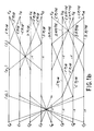
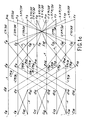
- - les figures 1a, 1b et 1c illustrent un graphe d'une transformation en cosinus discrète de
taille 16, - - les figures 2a, 2b et 2c illustrent un mode de réalisation d'un circuit selon l'invention pour la mise en oeuvre de la transformation représentée sur les figures 1a, 1b et 1c.
- FIGS. 1a, 1b and 1c illustrate a graph of a transformation into a discrete cosine of
size 16, - - Figures 2a, 2b and 2c illustrate an embodiment of a circuit according to the invention for the implementation of the transformation shown in Figures 1a, 1b and 1c.
A titre d'exemple, on décrit un circuit réalisant la transformée en cosinus discrète en temps réel pour une image organisée en pavés de 16×16 pixels.As an example, we describe a circuit realizing the discrete cosine transform in real time for an image organized in blocks of 16 × 16 pixels.
De manière connue, le débit de calcul est optimisé grâce à une structure de type "pipe line" et dans lequel le nombre d'opérations maximal que doit subir un échantillon de données est minimal. On minimise ainsi la quantité de mémorisations ou de regitres tampons utilisés.In known manner, the calculation throughput is optimized thanks to a "pipe line" type structure in which the maximum number of operations that a sample of data must undergo is minimal. This minimizes the amount of memorizations or buffer regs used.
La demande de brevet français no 85 15649, déjà citée, décrit le graphe de transformation en cosinus discrète pour la transformation d'une ligne ou d'une colonne de 16 pixels. Ce graphe est reproduit sur les figures 1a, 1b et 1c.The French patent application No. 85 15649, already mentioned, describes the discrete cosine transformation graph for the transformation of a line or a column of 16 pixels. This graph is reproduced in Figures 1a, 1b and 1c.
Le circuit de transformation en cosinus discrète d'un pavé de 16×16 pixels est réalisé sous la forme d'un seul circuit intégré comprenant dans l'ordre les modules suivants :
- un tableau de registre d'entrée réalisant la conversion de 16 pixels reçus en séquence et codés en parallèle, en 16 pixels délivrés bit à bit, en série,
- un opérateur de calcul de la transformation en cosinus discrète d'une ligne d'un pavé de 16×16 pixels,
- un tableau de registre de stockage et de transposition qui sert à mémoriser les coefficients de transformation en cosinus discrète ligne de tout le pavé avant d'attaquer les calculs de transformation en cosinus discrète colonne. Pour cela les différents coefficients qui arrivent ligne après ligne doivent être réarrangés par colonne. L'utilisation d'un tableau de registre avec décalage horizontal et vertical et de multiplexeurs d'entrée et de sortie permet de n'employer qu'un seul tableau de mémorisation,
- un opérateur de calcul de la transformation en cosinus discrète d'une colonne d'un pavé de 16×16 pixels,
- un tableau de registre de sortie qui réalise une conversion série-parallèle inverse de celle faite par le tableau de registre d'entrée.The circuit for transforming into a discrete cosine of a 16 × 16 pixel block is produced in the form of a single integrated circuit comprising the following modules in order:
- an input register table converting 16 pixels received in sequence and coded in parallel, into 16 pixels delivered bit by bit, in series,
- an operator for calculating the discrete cosine transformation of a line of a 16 × 16 pixel block,
- a storage and transposition register table which is used to memorize the coefficients of transformation in discrete cosine line of the whole block before attacking the calculations of transformation into discrete cosine column. For this, the different coefficients arriving line after line must be rearranged by column. The use of a register table with horizontal and vertical offset and of input and output multiplexers makes it possible to use only one storage table,
- an operator for calculating the discrete cosine transformation of a column of a 16 × 16 pixel block,
- an output register table which performs a reverse series-parallel conversion to that made by the input register table.
Les opérateurs de calcul de la transformée en cosinus discrète d'une ligne ou d'une colonne sont chacun conforme au graphe représenté sur les figures 1a, 1b et 1c.The operators for calculating the discrete cosine transform of a row or a column each conform to the graph shown in FIGS. 1a, 1b and 1c.
Dans ce graphe, chaque noeud représente une opération d'addition entre les branches qui aboutissent à ce noeud, et chaque branche représente une multiplication du nombre appliqué sur l'entrée de la branche par le coefficient associé à cette branche. Les coefficients notés Ciπ et Siπ correspondent respectivement à cos(iπ) et sin(iπ). On pourra se reporter à la demande de brevet français no 85 15649 pour une description plus détaillée du graphe.In this graph, each node represents an addition operation between the branches which lead to this node, and each branch represents a multiplication of the number applied to the entry of the branch by the coefficient associated with this branch. The coefficients denoted Ciπ and Siπ correspond respectively to cos (iπ) and sin (iπ). Reference may be made to French patent application No. 85 15649 for a more detailed description of the graph.
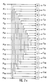
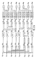
Un mode de réalisation selon l'invention d'un opérateur de calcul est représenté sur les figures 2a, 2b et 2c. Dans ce mode de réalisation, chaque opérateur comprend 44 multiplieurs du type parallèle-série et 72 additionneurs de type série. Pour chaque multiplieur, on a indiqué le coefficient multiplicatif appliqué à la donnée reçue en entrée. Pour chaque additionneur, on a précisé la nature de l'opération-addition ou soustraction- par les signs "+" et "-". Dans le cas d'une soustraction, on retranche l'opérande appliqué sur l'entrée inférieure du soustracteur de celui appliqué sur l'entrée supérieure.An embodiment according to the invention of a calculation operator is shown in Figures 2a, 2b and 2c. In this embodiment, each operator comprises 44 multipliers of the parallel-series type and 72 adders of the series type. For each multiplier, the multiplicative coefficient applied to the data received as input has been indicated. For each adder, the nature of the operation - addition or subtraction - has been specified by the signs "+" and "-". In the case of a subtraction, the operand applied to the lower input of the subtractor is subtracted from that applied to the upper input.
Les multiplieurs parallèle-série travaillent avec des multiplicateurs codés en code complément à 2 et sont délivrés avec le bit le moins significatif (LSB) en tête. Pour chaque multiplieur, le multiplicande qui représente un coefficient en cosinus ou en sinus est positif et câblé dans un additionneur de type "Manchester Carry Chain" modifié, pour prendre en compte le fait que ce multiplicande est fixe.The parallel-series multipliers work with multipliers coded in 2's complement code and are delivered with the least significant bit (LSB) at the head. For each multiplier, the multiplicand which represents a cosine or sine coefficient is positive and wired in a modified "Manchester Carry Chain" type adder, to take into account the fact that this multiplicand is fixed.
Outre l'opérateur de calcul proprement dit, chaque multiplieur comprend un registre d'accumulation et de décalage, et un registre tampon pour délivrer à l'étage de calcul suivant dans le graphe les données bit à bit. Ce registre de type parallèle-série comprend de plus un inverseur permettant de fournir à l'étage suivant le résultat avec le signe adéquat.In addition to the actual calculation operator, each multiplier includes an accumulation and shift register, and a buffer register for delivering bit by bit data to the next calculation stage in the graph. This register of parallel-series type further comprises an inverter making it possible to supply the stage according to the result with the appropriate sign.
Les additionneurs sont de type série et travaillent également sur des opérandes codés en code complément à 2. Chaque additionneur est câblé de manière à réaliser entre les deux opérandes l'opération souhaitée, addition ou soustraction.The adders are of the serial type and also work on operands coded in complement code to 2. Each adder is wired so as to carry out between the two operands the desired operation, addition or subtraction.
Des registres tampon BUFF supplémentaires peuvent être utilisés pour conserver les informations qui sont inchangées entre deux noeuds.Additional BUFF buffer registers can be used to keep information that is unchanged between two nodes.
Selon l'invention, un opérateur d'addition ou de multiplication est associé à chaque noeud ou chaque branche du graphe. En pratique, il est parfois possible de simplifier légèrement le circuit associé au graphe.According to the invention, an addition or multiplication operator is associated with each node or each branch of the graph. In practice, it is sometimes possible to slightly simplify the circuit associated with the graph.
Par exemple, dans la figure 1b, deux branches associées au même coefficient multiplicatif cos(π/4) partent du même noeud d₆. Il est bien sûr inutile de prévoir deux multiplieurs identiques pour un même noeud. Dans la figure 2b, on a donc prévu un seul multiplieur recevant le signal du noeud d₆, le résultat de la multiplication étant émis simultanément vers les additionneurs correspondant aux noeuds e₅ et e₆.For example, in Figure 1b, two branches associated with the same multiplicative coefficient cos (π / 4) start from the same node d₆. It is of course unnecessary to provide two identical multipliers for the same node. In FIG. 2b, a single multiplier is therefore provided receiving the signal from the node d₆, the result of the multiplication being transmitted simultaneously to the adders corresponding to the nodes e₅ and e₆.
On a procédé de la même manière pour les branches issues du noeud d₅. Cependant dans ce cas, le coefficient multiplicatif est égal à +cos( π/4) pour une branche et à -cos(π/4) pour l'autre branche. Le multiplieur utilisé a un coefficient multiplicatif de cos( π/4) ; le signe moins qui doit être ajouté pour la branche allant de d₅ à e₅ est restitué en remplaçant l'additioneur par un soustracteur en e₅.One proceeded in the same way for the branches resulting from the node d₅. However in this case, the multiplicative coefficient is equal to + cos (π / 4) for one branch and to -cos (π / 4) for the other branch. The multiplier used has a multiplicative coefficient of cos (π / 4); the minus sign which must be added for the branch going from d₅ to e₅ is restored by replacing the adder with a subtractor in e₅.
On note d'ailleurs qu'il est possible de ne réaliser dans tout le circuit que des multiplieurs à coefficient de multiplication positif, le signe éventuel de ce coefficient étant pris en compte lors de l'opération d'addition/soustraction qui suit.It should also be noted that it is possible to produce in the entire circuit only multipliers with a positive multiplication coefficient, the possible sign of this coefficient being taken into account during the following addition / subtraction operation.
Le demandeur a réalisé un circuit intégré pour la transformée en cosinus discrète décrite ci-dessus. Ce circuit comporte 80 000 transistors sur une puce de 49 mm². Ce circuit est réalisé dans une technologie CMOS à 2 microns avec deux niveaux de métallisation. La transformée en cosinus discrète d'un pavé de 16×16 pixels, codés chacun sur 8 bits, est réalisée en temps réel à une fréquence de 16 Mégahertz et avec une précision interne des calculs sur 14 bits.The applicant has produced an integrated circuit for the discrete cosine transform described above. This circuit includes 80,000 transistors on a 49 mm² chip. This circuit is produced in 2-micron CMOS technology with two metallization levels. The discrete cosine transformation of a 16 × 16 pixel block, each coded on 8 bits, is carried out in real time at a frequency of 16 Megahertz and with internal precision of the calculations on 14 bits.
Claims (3)
Applications Claiming Priority (2)
| Application Number | Priority Date | Filing Date | Title |
|---|---|---|---|
| FR8604845A FR2596892B1 (en) | 1986-04-04 | 1986-04-04 | CIRCUIT FOR PERFORMING LINEAR TRANSFORMATION ON A DIGITAL SIGNAL |
| FR8604845 | 1986-04-04 |
Publications (1)
| Publication Number | Publication Date |
|---|---|
| EP0241352A1 true EP0241352A1 (en) | 1987-10-14 |
Family
ID=9333903
Family Applications (1)
| Application Number | Title | Priority Date | Filing Date |
|---|---|---|---|
| EP87400707A Withdrawn EP0241352A1 (en) | 1986-04-04 | 1987-03-31 | Circuit for performing a linear transformation on a digital signal |
Country Status (4)
| Country | Link |
|---|---|
| US (1) | US4899300A (en) |
| EP (1) | EP0241352A1 (en) |
| JP (1) | JPS62239271A (en) |
| FR (1) | FR2596892B1 (en) |
Families Citing this family (3)
| Publication number | Priority date | Publication date | Assignee | Title |
|---|---|---|---|---|
| JP3102115B2 (en) * | 1991-12-27 | 2000-10-23 | 日本電気株式会社 | Discrete cosine transform processor |
| US5452466A (en) * | 1993-05-11 | 1995-09-19 | Teknekron Communications Systems, Inc. | Method and apparatus for preforming DCT and IDCT transforms on data signals with a preprocessor, a post-processor, and a controllable shuffle-exchange unit connected between the pre-processor and post-processor |
| KR100481067B1 (en) * | 2001-09-28 | 2005-04-07 | 브이케이 주식회사 | Apparatus for 2-D Discrete Cosine Transform using Distributed Arithmetic Module |
Citations (2)
| Publication number | Priority date | Publication date | Assignee | Title |
|---|---|---|---|---|
| FR2316663A1 (en) * | 1975-06-20 | 1977-01-28 | Nippon Electric Co | ARITHMETIC UNIT AND MORE PARTICULARLY ARITHMETIC UNIT FOR QUICK FOURIER TRANSFORMATION TREATMENT |
| US4080661A (en) * | 1975-04-22 | 1978-03-21 | Nippon Electric Co., Ltd. | Arithmetic unit for DFT and/or IDFT computation |
Family Cites Families (6)
| Publication number | Priority date | Publication date | Assignee | Title |
|---|---|---|---|---|
| US3581078A (en) * | 1967-11-24 | 1971-05-25 | Bell Telephone Labor Inc | Fast fourier analyzer |
| US4106103A (en) * | 1976-07-19 | 1978-08-08 | Xerox Corporation | Derivation of discrete Fourier transform components of a time dependent signal |
| US4385363A (en) * | 1978-12-15 | 1983-05-24 | Compression Labs, Inc. | Discrete cosine transformer |
| JPS57146345A (en) * | 1981-03-04 | 1982-09-09 | Toshiba Corp | 3n-th degree orthogonal transformation and inverse transformation system |
| US4621337A (en) * | 1983-08-11 | 1986-11-04 | Eastman Kodak Company | Transformation circuit for implementing a collapsed Walsh-Hadamard transform |
| US4646256A (en) * | 1984-03-19 | 1987-02-24 | The Board Of Trustees Of The Leland Stanford Junior University | Computer and method for the discrete bracewell transform |
-
1986
- 1986-04-04 FR FR8604845A patent/FR2596892B1/en not_active Expired
-
1987
- 1987-03-31 EP EP87400707A patent/EP0241352A1/en not_active Withdrawn
- 1987-04-02 JP JP62082164A patent/JPS62239271A/en active Pending
-
1989
- 1989-03-30 US US07/331,012 patent/US4899300A/en not_active Expired - Lifetime
Patent Citations (2)
| Publication number | Priority date | Publication date | Assignee | Title |
|---|---|---|---|---|
| US4080661A (en) * | 1975-04-22 | 1978-03-21 | Nippon Electric Co., Ltd. | Arithmetic unit for DFT and/or IDFT computation |
| FR2316663A1 (en) * | 1975-06-20 | 1977-01-28 | Nippon Electric Co | ARITHMETIC UNIT AND MORE PARTICULARLY ARITHMETIC UNIT FOR QUICK FOURIER TRANSFORMATION TREATMENT |
Also Published As
| Publication number | Publication date |
|---|---|
| JPS62239271A (en) | 1987-10-20 |
| FR2596892A1 (en) | 1987-10-09 |
| US4899300A (en) | 1990-02-06 |
| FR2596892B1 (en) | 1988-05-20 |
Similar Documents
| Publication | Publication Date | Title |
|---|---|---|
| EP0248729B1 (en) | Monodimensional cosine transform calculators and image coding and decoding devices using such calculators | |
| EP0314559A1 (en) | Calculating circuit using residue arithmetic | |
| FR2587819A1 (en) | DEVICE FOR CALCULATING A DISCRETE, SLIDING, NON-RECURSIVE FOURIER TRANSFORMATION AND APPLICATION THEREOF TO A RADAR SYSTEM | |
| EP3084588B1 (en) | Signal processing module, especially for a neural network and a neuronal circuit | |
| EP0262032B1 (en) | Binary adder having a fixed operand, and a parallel/serial multiplier comprising such an adder | |
| EP0511095A1 (en) | Coding and decoding method and apparatus for a digital signal | |
| EP0437876B1 (en) | Programmable serial multiplier | |
| EP0259231B1 (en) | Device for the determination of the digital transform of a signal | |
| EP0237382B1 (en) | Digital sampled signal cosine transforming device | |
| EP0536062B1 (en) | Cosina transform data processing method and apparatus | |
| EP0206892B1 (en) | Processing method for digital signals representing an original picture | |
| EP0241352A1 (en) | Circuit for performing a linear transformation on a digital signal | |
| EP0478431A1 (en) | Digital signal coding method and circuit for calculating scalar products of vectors and corresponding discrete cosinus transform | |
| EP1071008B1 (en) | Method for performing multiplication with accumulation in a Galois field | |
| EP0242258B1 (en) | Device for the execution of an algorithm (leroux-gueguen) for the coding of a signal by linear prediction | |
| EP0030194B1 (en) | Predictive stage for a dataflow compression system | |
| EP0341097B1 (en) | Recursive adder to calculate the sum of two operands | |
| EP0327445A1 (en) | Generalised digital multiplier, and digital filter using this multiplier | |
| FR2731813A1 (en) | COMPUTER PROCESSOR USING LOGARITHMIC CONVERSION AND METHOD OF USING THE SAME | |
| FR2570853A1 (en) | DEVICE FOR REAL-TIME PROCESSING OF DIGITAL SIGNAL BY CONVOLUTION | |
| CA2359198C (en) | Arithmetic unit for carrying out a cryptographic protocol | |
| EP0209446A1 (en) | Multiplier for the multiplication of two complex numbers | |
| FR2809835A1 (en) | Method for adding float point operands in multiplier by using normalizing stage that may prevent execution of increment stage after normalization | |
| EP0259902A1 (en) | Coding device with differential pulse code modulation, associated decoding device and transmission system comprising at least such a coding or decoding device | |
| FR2716321A1 (en) | Method and device for vector quantization of a digital signal, in particular applied to the compression of digital images. |
Legal Events
| Date | Code | Title | Description |
|---|---|---|---|
| PUAI | Public reference made under article 153(3) epc to a published international application that has entered the european phase |
Free format text: ORIGINAL CODE: 0009012 |
|
| AK | Designated contracting states |
Kind code of ref document: A1 Designated state(s): DE GB IT NL |
|
| 17P | Request for examination filed |
Effective date: 19880316 |
|
| 17Q | First examination report despatched |
Effective date: 19900226 |
|
| STAA | Information on the status of an ep patent application or granted ep patent |
Free format text: STATUS: THE APPLICATION IS DEEMED TO BE WITHDRAWN |
|
| 18D | Application deemed to be withdrawn |
Effective date: 19910626 |