EP0536062B1 - Cosina transform data processing method and apparatus - Google Patents
Cosina transform data processing method and apparatus Download PDFInfo
- Publication number
- EP0536062B1 EP0536062B1 EP92420332A EP92420332A EP0536062B1 EP 0536062 B1 EP0536062 B1 EP 0536062B1 EP 92420332 A EP92420332 A EP 92420332A EP 92420332 A EP92420332 A EP 92420332A EP 0536062 B1 EP0536062 B1 EP 0536062B1
- Authority
- EP
- European Patent Office
- Prior art keywords
- coefficient
- cos
- values
- data
- par
- Prior art date
- Legal status (The legal status is an assumption and is not a legal conclusion. Google has not performed a legal analysis and makes no representation as to the accuracy of the status listed.)
- Expired - Lifetime
Links
Images


Classifications
-
- G—PHYSICS
- G06—COMPUTING; CALCULATING OR COUNTING
- G06F—ELECTRIC DIGITAL DATA PROCESSING
- G06F17/00—Digital computing or data processing equipment or methods, specially adapted for specific functions
- G06F17/10—Complex mathematical operations
- G06F17/14—Fourier, Walsh or analogous domain transformations, e.g. Laplace, Hilbert, Karhunen-Loeve, transforms
- G06F17/147—Discrete orthonormal transforms, e.g. discrete cosine transform, discrete sine transform, and variations therefrom, e.g. modified discrete cosine transform, integer transforms approximating the discrete cosine transform
Definitions
- the present invention relates to a method and a digital signal processing circuit to accomplish a transformation function called "cosine transformation discreet ", often referred to in the technical literature by the Anglo-Saxon acronym DCT.
- This type of transformation matches a matrix (a block) of digital output values or coefficients to an array of digital input values. This transformation is particularly useful for performing compression images for transmission at a higher rate than that which would be possible if the corresponding signals were sent without transformation.
- the cosine transformation does in itself no information compression; it is an encoder placed downstream of the transformation circuit that does the compression. But the transformation circuit facilitates compression by providing easy to compress information at the encoder input.
- This transformation circuit finds its most common application in digital transmission of black and white images or in colors and it is by referring to this example that the present invention will be described. So the matrix of values digital input will correspond to a pixel matrix.
- For carry out the cosine transformation we decompose the image or the frame that we are trying to transmit in blocks of n rows and n columns, each point of the block corresponding to a pixel represented by a digital value coded for example on eight bits. This value corresponds for example to the luminance or to a pixel chrominance component.
- the cosine transformation does match a block of nxn coefficients.
- f (x, y) the pixel value of x and y coordinates in the block.
- F (u, v) the coefficient calculated according to the cosine transformation and placed at the intersection of row u and column v in the transformed block.
- n 8 and x, y, u and v are between 0 and 7.
- the computing power of the DCT operator to realize depends on the number of blocks to be processed per second. For pictures conventional or high definition television several hundred kiloblocks per second and for that, we have use of specialized integrated circuits implementing complex algorithmic functions, such as the Byong Gi Lee. These circuits allow processing extremely fast but have the drawback of require many components to perform in parallel various operations and therefore occupy a large area over an integrated circuit.
- an object of the present invention is to provide a method and a circuit for processing information by discrete cosine transform achievable as a circuit small integrated.
- the present invention is based on an analysis of the formula (1) above of the discrete cosine transform (DCT). While the methods of the prior art and the circuits for essentially implementing them were intended to perform in parallel as many operations as possible at cost a multiplication of the electronic components used, the present invention aims to perform these serial operations of the as simple as possible and using as few components as possible possible while obtaining a power of sufficient calculation to process image sequences including for example of the order of a few tens of kiloblocks per second.
- DCT discrete cosine transform
- each value of F (u, v) corresponds to the sum of 64 products of f (x, y) by a coefficient P of the absolute value type cos [n (x, u) ⁇ / 16] ⁇ cos [n (y, v) ⁇ / 16] affected by a positive sign or negative.
- takes 49 different values.
- the present invention proposes to store in tables, on the one hand, the sign, on the other hand, the value absolute of each product cos [n (x, u) ⁇ / 16] ⁇ cos [n (y, v) ⁇ / 16] to serve as a basis for treating DCT. More specifically, the present invention proposes to use in a first stage of memory two tables, one of which receives the current value of x and from u and provides n (x, u) and Sgn (x, u) and from which the other receives the current value of y and v and provides n (y, v) and Sgn (y, v).
- n (x, u) and n (y, v) together serve to address a second memory stage which contains the absolute values of P (cosine products).
- P cosine products
- Figure 1 is a block diagram showing a first embodiment of a DCT circuit according to the present invention.
- the pixels of block x, y to be processed are stored in a memory 1 which initially contains the 64 pixels of the block 8 * 8 to be processed.
- a memory 1 which initially contains the 64 pixels of the block 8 * 8 to be processed.
- it will be beneficial to double the capacity of this memory and to provide it with double access. While processing one block, the next will be acquired simultaneously according to conventional techniques.
- a coordinate generator y, x, u, v sequentially supplies the 64 combinations of values of u and v and, for each pair (u, v), scans in 64 clock strokes the 64 possible values of x, y, c 'is to say the 64 pixels of the block memory 1.
- the scanning order of the coordinates x, y is arbitrary, but that the scanning order of the pairs (u, v) will be chosen as a function of the order that we want to obtain at the output of the circuit. For example, if we want to provide an output conforming to the CCITT H261 standard, the scanning of the matrix u, v will be in a zigzag.
- a table 7 provides for each pair x, u the value corresponding to the sign of p (x, u) (hereinafter called Sgn [p (x, u)] or more simply Sgn (x, u)). This table also provides the half n (x, u) of the memory address 3.
- a table 9 fills similar functions for y and v.
- a multiplier 11 For each pair x, y, a multiplier 11 provides the product of the value f (x, y) of the current pixel by P. This product is sent to a total isator 13, which, every 64 clock ticks, provides for a couple u, v, the value of the coefficient F (u, v) corresponding.
- the totalizer 13 includes an adder-subtractor 15 and an accumulator 17. The accumulator 17 stores during 64 clock ticks the algebraic sum of the outputs of the adder 15.
- This adder receives on a first enter the partial result accumulated in accumulator 17 and on its second entry the current product P ⁇ f (x, y) affected by sign (+) or (-) depending on the output of a determination circuit of sign 19 which provides the algebraic product of Sgn (x, u) and Sgn (y, v) obtained at the outputs of tables 7 and 9.
- the coordinate generator provides each of the coordinates on 3 bits, and that if the pixels in the block memory are defined on 8 bits, so as not to lose in definition, the P value must be defined substantially on 12 bits.
- this expression means that for four pixels two by two symmetrical with respect to central axes of the array of pixels x, y, i.e. the pixels (x, y) (x ', y) (x, y') (x ', y'), the multiplicative coefficient P will be the same provided that the data corresponding to the pixels are assigned a positive or negative sign depending on their location.
- Two conclusions are drawn from this, on the one hand that the dimensions of the memories 7 and 9 of figure 1 can be reduced, other it is possible to calculate a coefficient F (u, v) in just 16 clock strokes instead of 64. So, we multiplies by 4 the speed of calculation to arrive at speeds of the order of 16 kblocks / s, i.e. a good speed sufficient for processing videophone information such as this has been indicated previously.
- Figure 3 shows schematically a circuit implementing this second embodiment of this invention.
- the circuit of Figure 3 includes a block memory 1, a coefficient memory P 3, a data generator 5, tables 7 and 9 providing respectively the values n (x, u) and n (y, v) for addressing ROM 3 and also providing the signs of p (x, u) and p (y, v) to a circuit 19 which provides the sign of P.
- La absolute value of P is supplied to a multiplier 11 whose output goes to a totalizer 13 which cyclically supplies the successive values F (u, v).
- the essential difference with the circuit of FIG. 1 is that the coordinate generator 5 simultaneously addresses four pixels in memory 1, namely the pixels f (x, y), f (x ', y), f (x, y ') and f (x', y ').
- a summing circuit 21 provides the value of f (x, y) + by (u) f (x ', y) + by (v) [(f (x, y') + by (u) f (x ', y')].
- circuit 21 The output of circuit 21 is sent to the second multiplier input 11.
- the summing circuit 21 includes three adders / subtractors.
- the first, 23, provides f (x, y) + by (u) ⁇ f (x ', y) and receives input by (u) in origin of the coordinate generator 5.
- the second, 24, provides f (x, y ') + by (u) ⁇ f (x', y ') and receives input by (u) in origin of the coordinate generator 5.
- the third, 25, provides the final result and receives the signal by (v) from the generator coordinates 5.
- Circuit 21 including only adders is particularly simple to carry out and will occupy a weak surface on an integrated circuit.
- FIG. 4 represents the table of values of n (x, u) and of Sgn (x, u) corresponding to each of the eight values of u and four values of x scanned (remember that n was defined in formulas (2) and (3)).
- This equation has the same form as equation (1) of determination of direct CSD. So the circuit of figure 1 allows, without modification, to perform a reverse CSD calculation, by switching f (x, y) and F (u, v).
- This circuit includes a block memory 1 but, instead of being blocks of pixels f (x, y), these are now blocks of coefficients F (u, v).
- ROM 3 ROM contains values of P, i.e. absolute values of cosine products of n ⁇ / 16, and is associated with a generator of coordinates 5 and to value determination tables of terms n (x, u) and n (y, v) 7 and 9.
- the multiplier 11 receives directly, on the one hand, the value F (u, v) coming from the memory block 1, on the other hand, P from ROM 3.
- the result of the multiplication is sent simultaneously to four totalizers 31, 32, 33, 34 for which the choice between an addition and a subtraction is determined based on the output Sgn of circuit 19 and values of the parities of u and v such as provided at the output of the coordinate generator 5.
- the outputs of the four totalizers being supplied simultaneously, they are temporarily stored in registers 35, 36, 37, 38 before being supplied to an output line 40 to a appropriate rhythm.
- the pixel outputs on line 40 are supplied in an order imposed by the satisfaction of the equations (5). That is to say that we obtain pixels sequentially corresponding to four positions 2 to 2 symmetrical about to the central axes of the pixel matrix. This does not match generally not at a desired matrix scan order pixels. We will therefore sometimes need to have an exit permuter 41 intended to put the pixels in a desired order on a exit 42.
Landscapes
- Physics & Mathematics (AREA)
- Engineering & Computer Science (AREA)
- General Physics & Mathematics (AREA)
- Mathematical Physics (AREA)
- Mathematical Analysis (AREA)
- Data Mining & Analysis (AREA)
- Computational Mathematics (AREA)
- Pure & Applied Mathematics (AREA)
- Mathematical Optimization (AREA)
- Theoretical Computer Science (AREA)
- Discrete Mathematics (AREA)
- Databases & Information Systems (AREA)
- Software Systems (AREA)
- General Engineering & Computer Science (AREA)
- Algebra (AREA)
- Complex Calculations (AREA)
- Compression Or Coding Systems Of Tv Signals (AREA)
- Compression Of Band Width Or Redundancy In Fax (AREA)
- Image Processing (AREA)
Description
La présente invention concerne un procédé et un circuit de traitement numérique de signal pour accomplir une fonction de transformation appelée "transformation cosinus discrète", souvent désignée dans la littérature technique par le sigle anglo-saxon DCT.The present invention relates to a method and a digital signal processing circuit to accomplish a transformation function called "cosine transformation discreet ", often referred to in the technical literature by the Anglo-Saxon acronym DCT.
Ce type de transformation fait correspondre une matrice (un bloc) de valeurs numériques de sortie ou coefficients à une matrice de valeurs numériques d'entrée. Cette transformation est particulièrement utile pour effectuer de la compression d'images pour une transmission à un débit plus élevé que celui qui serait possible si les signaux correspondants étaient envoyés sans transformation.This type of transformation matches a matrix (a block) of digital output values or coefficients to an array of digital input values. This transformation is particularly useful for performing compression images for transmission at a higher rate than that which would be possible if the corresponding signals were sent without transformation.
La transformation cosinus n'effectue en elle-même aucune compression d'information ; c'est un codeur placé en aval du circuit de transformation qui fait la compression. Mais le circuit de transformation facilite la compression en fournissant à l'entrée du codeur des informations faciles à comprimer. Ce circuit de transformation trouve son application la plus courante dans la transmission numérique d'images en noir et blanc ou en couleurs et c'est en se référant à cet exemple que la présente invention sera décrite. Ainsi, la matrice de valeurs numériques d'entrée correspondra à une matrice de pixels. Pour réaliser la transformation cosinus, on décompose l'image ou la trame que l'on cherche à transmettre en blocs de n rangées et n colonnes, chaque point du bloc correspondant à un pixel représenté par une valeur numérique codée par exemple sur huit bits. Cette valeur correspond par exemple à la luminance ou à une composante de chrominance du pixel.The cosine transformation does in itself no information compression; it is an encoder placed downstream of the transformation circuit that does the compression. But the transformation circuit facilitates compression by providing easy to compress information at the encoder input. This transformation circuit finds its most common application in digital transmission of black and white images or in colors and it is by referring to this example that the the present invention will be described. So the matrix of values digital input will correspond to a pixel matrix. For carry out the cosine transformation, we decompose the image or the frame that we are trying to transmit in blocks of n rows and n columns, each point of the block corresponding to a pixel represented by a digital value coded for example on eight bits. This value corresponds for example to the luminance or to a pixel chrominance component.
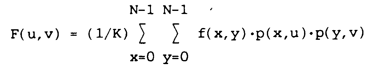
Au bloc de nxn pixels, la transformation cosinus fait correspondre un bloc de nxn coefficients. On appelera f(x,y) la valeur du pixel de coordonnées x et y dans le bloc. On appelera F(u,v) le coefficient calculé selon la transformation cosinus et placé à l'intersection de la ligne u et de la colonne v dans le bloc transformé. Dans le cas le plus courant n=8 et x, y, u et v sont compris entre 0 et 7.At the block of nxn pixels, the cosine transformation does match a block of nxn coefficients. We will call f (x, y) the pixel value of x and y coordinates in the block. We will call F (u, v) the coefficient calculated according to the cosine transformation and placed at the intersection of row u and column v in the transformed block. In the most common case n = 8 and x, y, u and v are between 0 and 7.
Dans toute la description suivante, on considérera
seulement ce cas particulier de blocs de 8x8 pixels. L'homme de
l'art pourra facilement déduire ou trouver dans des ouvrages
spécialisés les formules correspondantes pour des blocs de nxn
pixels. Ainsi, dans le cas particulier considéré, une transformation
cosinus s'explicite par la relation suivante :

= 1 pour u,v ≠ 0.In all of the following description, we will only consider this particular case of 8 × 8 pixel blocks. Those skilled in the art can easily deduce or find in specialized works the corresponding formulas for blocks of nxn pixels. Thus, in the particular case considered, a cosine transformation is explained by the following relation:
= 1 for u, v ≠ 0.
La puissance de calcul de l'opérateur DCT à réaliser dépend du nombre de blocs à traiter par seconde. Pour des images de télévision classiques ou haute définition, il faut traiter plusieurs centaines de kiloblocs par seconde et pour cela, on a recours à des circuits intégrés spécialisés mettant en oeuvre des fonctions algorithmiques complexes, tels que l'algorithme de Byong Gi Lee. Ces circuits permettent d'effectuer des traitements extrêmement rapides mais présentent l'inconvénient de nécessiter de nombreux composants pour effectuer en parallèle diverses opérations et occupent donc une surface importante sur un circuit intégré.The computing power of the DCT operator to realize depends on the number of blocks to be processed per second. For pictures conventional or high definition television several hundred kiloblocks per second and for that, we have use of specialized integrated circuits implementing complex algorithmic functions, such as the Byong Gi Lee. These circuits allow processing extremely fast but have the drawback of require many components to perform in parallel various operations and therefore occupy a large area over an integrated circuit.
Des exemples de circuits classiques de calcul de DCT apparaissent par exemple dans "Proceedings of the 1990 IEEE Int. Symp. on Circuits and Systems, vol. 2/4, 1 mai 1990, New Orleans (USA), pages 1620-1623, U.Siöström et al : "Discrete Cosine Transform Chip for Real Time Video Applications" ; et dans "Proceedings of TECNON 87, IEEE Computers Society Press, New York (USA), Vol. 2/3, 25 août 1987, Seoul (Korea), pages 595-599, Aire Heiman et al : "A Universal Real Time Transformer for Image Coding".Examples of classic DCT calculation circuits appear for example in "Proceedings of the 1990 IEEE Int. Nice. on Circuits and Systems, vol. 2/4, May 1, 1990, New Orleans (USA), pages 1620-1623, U.Siöström et al: "Discrete Cosine Transform Chip for Real Time Video Applications "; and in "Proceedings of TECNON 87, IEEE Computers Society Press, New York (USA), Vol. 2/3, 25 August 1987, Seoul (Korea), pages 595-599, Area Heiman et al: "A Universal Real Time Transformer for Image Coding ".
Par habitude, on utilise également de tels circuits quand le problème à résoudre est plus simple et que l'on cherche seulement à traiter un plus faible nombre de blocs par seconde, ce qui est par exemple le cas dans des applications de traitement d'image du type visiophone pour lesquelles un traitement de l'ordre de 10 kiloblocs par seconde semble suffisant.By habit, such circuits are also used when the problem to be solved is simpler and we are looking for only to process a lower number of blocks per second, this is for example the case in processing applications image type videophone for which a processing of the order of 10 kiloblocks per second seems sufficient.
Ainsi, un objet de la présente invention est de prévoir un procédé et un circuit de traitement d'informations par transformée cosinus discrète réalisable sous forme de circuit intégré de faible dimension.Thus, an object of the present invention is to provide a method and a circuit for processing information by discrete cosine transform achievable as a circuit small integrated.
Pour atteindre cet objet, la présente invention prévoit
un procédé de traitement de données par transformation
cosinus discrète (DCT) faisant correspondre à un tableau f(x,y)
de NxN données un tableau F(u,v) de NxN coefficients selon la
relation suivante :
= 1 pour u,v ≠ 0.
consistant à déterminer séquentiellement chaque coefficient F(u,v) pour un couple de coordonnées u,v en réalisant les étapes suivantes : rechercher dans une table pour un premier couple x,y la valeur absolue et le signe du coefficient P=p(x,u)·p(y,v) ; multiplier la valeur absolue de P par f(x,y) ; introduire le résultat de la multiplication additivement ou soustractivement dans un accumulateur en fonction dudit signe ; et répéter l'opération pour toutes les valeurs du couple x,y et extraire le résultat fourni par l'accumulateur.

= 1 pour u,v ≠ 0,
= 1 for u, v ≠ 0.
consisting in sequentially determining each coefficient F (u, v) for a couple of coordinates u, v by carrying out the following steps: searching in a table for a first couple x, y the absolute value and the sign of the coefficient P = p (x , u) · p (y, v); multiply the absolute value of P by f (x, y); introducing the result of the multiplication additively or subtractively into an accumulator according to said sign; and repeat the operation for all the values of the couple x, y and extract the result supplied by the accumulator.
= 1 for u, v ≠ 0,
Réciproquement, la présente invention prévoit un
circuit de traitement de coefficients par transformée cosinus
discrète inverse faisant cerrespondre à un tableau de NxN
coefficients (F(u,v)) un tableau de NxN données (f(x,y)) selon
la relation suivante :
![]()
= 1 pour u,v ≠ 0.
Ce circuit comprend une mémoire du tableau de coefficients ; une mémoire des produits P = cos[n(x,u)π/2N]·cos[n(y,v)π/2N], où n(x,u) et n(y,v) sont des entiers compris entre 1 et (N/2)-1 ; une table des signes de cos[n(x,u)π/2N] et de cos [n(y,v)π/2N], et de n(x,u) et de n(y,v) ; un générateur de coordonnées fournissant séquentiellement des couples de valeurs (x,y) correspondant au 1er quadrant du tableau de données ainsi que des signaux par(u) et par(v) égaux à +1 ou -1 selon que u et v sont pair ou impair et, pour chaque couple (x,y), toutes les valeurs des couples (u,v) ; un multiplieur effectuant le produit de P par une combinaison des coefficients de la mémoire de coefficients ; et quatre totaliseurs effectuant une soutraction ou une addition du résultat de la multiplication avec les résultats précédents en fonction du signe fourni par la table de signes et des valeurs de par (u) et de par (v) pour fournir respectivement f(x,y), f(x',y), f(x,y') et f(x',y'), où x'=N-1-x et y'=N-1-y.Conversely, the present invention provides a circuit for processing coefficients by inverse discrete cosine transform making an array of NxN coefficients (F (u, v)) correspond to an array of NxN data (f (x, y)) according to the following relationship :
= 1 for u, v ≠ 0.
This circuit includes a memory of the coefficient table; a memory of the products P = cos [n (x, u) π / 2N] · cos [n (y, v) π / 2N], where n (x, u) and n (y, v) are integers included between 1 and (N / 2) -1; a table of signs of cos [n (x, u) π / 2N] and cos [n (y, v) π / 2N], and of n (x, u) and n (y, v); a coordinate generator sequentially supplying pairs of values (x, y) corresponding to the 1st quadrant of the data table as well as signals by (u) and by (v) equal to +1 or -1 depending on whether u and v are even or odd and, for each couple (x, y), all the values of the couples (u, v); a multiplier performing the product of P by a combination of the coefficients in the coefficient memory; and four totalizers performing a withdrawal or an addition of the result of the multiplication with the preceding results according to the sign provided by the table of signs and the values of by (u) and by (v) to supply respectively f (x, y ), f (x ', y), f (x, y') and f (x ', y'), where x '= N-1-x and y' = N-1-y.
Ces objets, caractéristiques et avantages ainsi que
d'autres de la présente invention seront exposés en détail dans
la description suivante de modes de réalisation particuliers
faite en relation avec les figures jointes parmi lesquelles :
La présente invention se base sur une analyse de la formule (1) ci-dessus de la transformée cosinus discrète (DCT). Alors que les procédés de l'art antérieur et les circuits pour les mettre en oeuvre visaient essentiellement à effectuer en parallèle le plus grand nombre d'opérations possibles au coût d'une multiplication des composants électroniques utilisés, la présente invention vise à réaliser ces opérations en série de la façon la plus simple possible et en utilisant le moins de composants électroniques possibles tout en obtenant une puissance de calcul suffisante pour traiter des séquences d'images comprenant par exemple de l'ordre de quelques dizaines de kiloblocs par seconde.The present invention is based on an analysis of the formula (1) above of the discrete cosine transform (DCT). While the methods of the prior art and the circuits for essentially implementing them were intended to perform in parallel as many operations as possible at cost a multiplication of the electronic components used, the present invention aims to perform these serial operations of the as simple as possible and using as few components as possible possible while obtaining a power of sufficient calculation to process image sequences including for example of the order of a few tens of kiloblocks per second.
La formule (1) ci-dessus peut se réécrire
![]()
P(x,u,y,v) = p(x,u)p(y,v)
avec :
Sgn[p(x,u)] ou Sgn[p(y,v)] = ±1 désigne le signe de p.
Dans ces formules, en effet :
si u=0, le cosinus est égal à 1 et p(x,u)=c(u)=1/√2=cos4π/16,
si u≠0, c(u)=1 et p(x,u)=cos[(2x+1)uπ/16].Formula (1) above can be rewritten ![]()
P (x, u, y, v) = p (x, u) p (y, v) with:
Sgn [p (x, u)] or Sgn [p (y, v)] = ± 1 denotes the sign of p.
In these formulas, in fact:
if u = 0, the cosine is equal to 1 and p (x, u) = c (u) = 1 / √2 = cos4π / 16,
if u ≠ 0, c (u) = 1 and p (x, u) = cos [(2x + 1) uπ / 16].
Il en est de même pour c(v) et p(y,v).The same is true for c (v) and p (y, v).
Ceci signifie que p(x,u) ou p(y,v)) est toujours égal à la valeur absolue du cosinus d'un arc du premier quadrant multiple de n/16 affectée d'un signe positif ou négatif. En conséquence, chaque valeur de F(u,v) correspond à la somme de 64 produits de f(x,y) par un coefficient P du type valeur absolue de cos[n(x,u)π/16]·cos[n(y,v)π/16] affecté d'un signe positif ou négatif. Par ailleurs, |P| prend 49 valeurs différentes. This means that p (x, u) or p (y, v)) is always equal to the absolute value of the cosine of an arc of the first quadrant multiple of n / 16 with a positive or negative sign. In consequence, each value of F (u, v) corresponds to the sum of 64 products of f (x, y) by a coefficient P of the absolute value type cos [n (x, u) π / 16] · cos [n (y, v) π / 16] affected by a positive sign or negative. In addition, | P | takes 49 different values.
Ainsi, la présente invention propose de mémoriser dans des tables, d'une part, le signe, d'autre part, la valeur absolue de chacun des produits cos[n(x,u)π/16]·cos [n(y,v)π/16] pour servir de base au traitement de DCT. Plus particulièrement, la présente invention propose d'utiliser dans un premier étage de mémoire deux tables dont l'une reçoit la valeur courante de x et de u et fournit n(x,u) et Sgn(x,u) et dont l'autre reçoit la valeur courante de y et de v et fournit n(y,v) et Sgn(y,v). Les valeurs de n(x,u) et de n(y,v) servent ensemble d'adresse à un deuxième étage de mémoire qui contient les valeurs absolues de P (produits de cosinus). En reprenant les expressions précédentes, on notera que, dans le cas particulier considéré de blocs 8x8, les tables sont de relativement petites dimensions (64 mots de 4 bits pour chacune des premières tables et 49 mots de typiquement 12 bits pour le deuxième étage de mémoire).Thus, the present invention proposes to store in tables, on the one hand, the sign, on the other hand, the value absolute of each product cos [n (x, u) π / 16] · cos [n (y, v) π / 16] to serve as a basis for treating DCT. More specifically, the present invention proposes to use in a first stage of memory two tables, one of which receives the current value of x and from u and provides n (x, u) and Sgn (x, u) and from which the other receives the current value of y and v and provides n (y, v) and Sgn (y, v). The values of n (x, u) and n (y, v) together serve to address a second memory stage which contains the absolute values of P (cosine products). Using the previous expressions, it will be noted that, in the particular case considered of 8 × 8 blocks, the tables are relatively small (64 words of 4 bits for each of the first tables and 49 words typically 12 bits for the second memory stage).
La figure 1 est un schéma sous forme de blocs représentant un premier mode de réalisation de circuit de DCT selon la présente invention.Figure 1 is a block diagram showing a first embodiment of a DCT circuit according to the present invention.
Les pixels du bloc x,y à traiter sont mémorisés dans
une mémoire 1 qui contient initialement les 64 pixels du bloc
8*8 à traiter. En pratique, pour éviter les pertes de temps lors
de la mémorisation du bloc suivant, on aura intérêt à doubler la
capacité de cette mémoire et à la munir d'un double accès.
Pendant que l'on traite un bloc, le suivant sera acquis simultanément
selon des techniques classiques.The pixels of block x, y to be processed are stored in
a
Une mémoire morte 3 contient tous les produits
Une table 7 fournit pour chaque couple x,u la valeur
correspondante du signe de p(x,u) (appelé ci-après Sgn[p(x,u)]
ou plus simplement Sgn(x,u)). Cette table fournit également la
moitié n(x,u) de l'adresse de la mémoire 3. Une table 9 remplit
des fonctions similaires pour y et v.A table 7 provides for each pair x, u the value
corresponding to the sign of p (x, u) (hereinafter called Sgn [p (x, u)]
or more simply Sgn (x, u)). This table also provides the
half n (x, u) of the
Pour chaque couple x, y, un multiplieur 11 fournit le
produit de la valeur f(x,y) du pixel en cours par P. Ce produit
est envoyé à un total isateur 13, qui, tous les 64 coups d'horloge,
fournit pour un couple u, v, la valeur du coefficient F(u,v)
correspondant. Le totalisateur 13 comprend un additionneur-soustracteur
15 et un accumulateur 17. L'accumulateur 17 stocke
pendant 64 coups d'horloge la somme algébrique des sorties de
l'additionneur 15. Cet additionneur reçoit sur une première
entrée le résultat partiel accumulé dans l'accumulateur 17 et
sur sa deuxième entrée le produit en cours P·f(x,y) affecté du
signe (+) ou (-) selon la sortie d'un circuit de détermination
de signe 19 qui fournit le produit algébrique de Sgn(x,u) et de
Sgn(y,v) obtenu aux sorties des tables 7 et 9.For each pair x, y, a
Avec le circuit de la figure 1, il faut 64 coups
d'horloge pour calculer chaque coefficient F(u,v) et donc
64. 64=4096 coups d'horloge pour calculer les 64 coefficients de
la DCT d'un bloc. L'élément dont le fonctionnement est le plus
lent parmi les circuits de la figure 1 est le multiplieur 11.
Une technologie qui autorise qu'une multiplication soit effectuée
en une période d'une horloge à 16 MHz permettra une puissance
de calcul d'environ 4 kiloblocs par seconde.With the circuit of figure 1, it takes 64 strokes
to calculate each coefficient F (u, v) and therefore
64. 64 = 4096 clock ticks to calculate the 64 coefficients of
the CSD of a block. The most functioning element
slow among the circuits of figure 1 is the
D'autre part, pour se faire une idée plus précise de l'encombrement du circuit de la figure 1, on notera que pour un bloc 8·8, le générateur de coordonnées fournit chacune des coordonnées sur 3 bits, et que, si les pixels de la mémoire de blocs sont définis sur 8 bits, pour ne pas perdre en définition, la valeur de P doit être définie sensiblement sur 12 bits. On the other hand, to get a more precise idea of the size of the circuit of FIG. 1, it will be noted that for a block 8 · 8, the coordinate generator provides each of the coordinates on 3 bits, and that if the pixels in the block memory are defined on 8 bits, so as not to lose in definition, the P value must be defined substantially on 12 bits.
Dans un deuxième mode de réalisation de la présente
invention, on cherche à augmenter la vitesse possible de fourniture
des coefficients F(u,v) en utilisant encore un seul multiplieur
réalisant l'opération de multiplication d'un nombre de 11
bits par un nombre de 12 bits en un temps d'une horloge à 16
MHz. Pour cela, on se base sur une analyse plus détaillée des
coefficients p. Il est alors possible de noter que ces coefficients
répondent à la propriété suivante :
Soit x' = 7-x ;
alors :
p(x',u) = + p(x,u) si u est pair
- p(x,u) si u est impairIn a second embodiment of the present invention, it is sought to increase the possible speed of supply of the coefficients F (u, v) by still using a single multiplier performing the operation of multiplying an 11-bit number by a
Let x '= 7-x;
so :
p (x ', u) = + p (x, u) if u is even
- p (x, u) if u is odd
En utilisant la notation par(u) pour désigner la
parité de u, cette expression peut s'écrire
par(u) = +1 si u est pair
-1 si u est impair.Using the notation by (u) to denote the parity of u, this expression can be written
by (u) = +1 if u is even
-1 if u is odd.
Ainsi, en reprenant l'expression (1) ci-dessus et en
tenant compte de la remarque précédente, on peut écrire :

Comme le montre la figure 2, cette expression signifie
que, pour quatre pixels deux à deux symétriques par rapport aux
axes centraux du tableau de pixels x,y, c'est-à-dire les pixels
(x,y) (x',y) (x,y') (x',y'), le coefficient multiplicatif P sera
le même sous réserve que les données correspondant aux pixels
soient affectées d'un signe positif ou négatif selon leur emplacement.
Par contre, la somme double ne porte plus que sur 4x4=16
termes au lieu de 8x8=64 comme cela a été indiqué précédemment.
On en tire deux conclusions, d'une part que les dimensions des
mémoires 7 et 9 de la figure 1 peuvent être réduites, d'autre
part qu'il est possible d'effectuer le calcul d'un coefficient
F(u,v) en seulement 16 coups d'horloge au lieu de 64. Ainsi, on
multiplie par 4 la rapidité du calcul pour arriver à des rapidités
de l'ordre de 16 kblocs/s, c'est-à-dire une rapidité bien
suffisante pour le traitement d'informations de visiophone comme
cela a été indiqué précédemment.As Figure 2 shows, this expression means
that for four pixels two by two symmetrical with respect to
central axes of the array of pixels x, y, i.e. the pixels
(x, y) (x ', y) (x, y') (x ', y'), the multiplicative coefficient P will be
the same provided that the data corresponding to the pixels
are assigned a positive or negative sign depending on their location.
On the other hand, the double sum only relates to 4x4 = 16
terms instead of 8x8 = 64 as previously indicated.
Two conclusions are drawn from this, on the one hand that the dimensions of the
La figure 3 représente schématiquement un circuit
mettant en oeuvre ce deuxième mode de réalisation de la présente
invention. Comme le circuit de la figure 1, le circuit de la
figure 3 comprend une mémoire de bloc 1, une mémoire de coefficients
P 3, un générateur de données 5, des tables 7 et 9
fournissant respectivement les valeurs n(x,u) et n(y,v) pour
l'adressage de la ROM 3 et fournissant aussi les signes de
p(x,u) et p(y,v) à un circuit 19 qui fournit le signe de P. La
valeur absolue de P est fournie à un multiplieur 11 dont la
sortie va à un totalisateur 13 qui fournit cycliquement les
valeurs successives F(u,v).Figure 3 shows schematically a circuit
implementing this second embodiment of this
invention. Like the circuit of figure 1, the circuit of
Figure 3 includes a
La différence essentielle avec le circuit de la
figure 1 est que le générateur de coordonnées 5 adresse simultanément
quatre pixels dans la mémoire 1, à savoir les pixels
f(x,y), f(x',y), f(x,y') et f(x',y'). Un circuit de sommation 21
fournit la valeur de
La sortie du circuit 21 est envoyée à la deuxième
entrée du multiplieur 11.The output of
Dans la réalisation décrite, le circuit de sommation
21 comprend trois additionneurs/soustracteurs. Le premier, 23,
fournit f(x,y)+par(u)·f(x',y) et reçoit l'entrée par(u) en
provenance du générateur de coordonnées 5. De même, le deuxième,
24, fournit f(x,y')+par(u)·f(x',y') et reçoit l'entrée par(u) en
provenance du générateur de coordonnées 5. Le troisième, 25,
fournit le résultat final et reçoit le signal par(v) du générateur
de coordonnées 5.In the embodiment described, the summing
Dans ce mode de réalisation, pour chaque couple de
valeurs u,v, on balayage seulement quatre valeurs de y et quatre
valeurs de x ce qui réduit de la façon indiquée précédemment la
durée du fonctionnement au coût de l'addition du circuit de
sommation 21. Le circuit 21 ne comprenant que des additionneurs
est particulièrement simple à réaliser et occupera une faible
surface sur un circuit intégré.In this embodiment, for each pair of
values u, v, we scan only four values of y and four
values of x which reduces in the way indicated previously the
operating time at the cost of adding the
Pour aider à la compréhension de la présente invention, la figure 4 représente le tableau des valeurs de n(x,u) et de Sgn(x,u) correspondant à chacune des huit valeurs de u et des quatre valeurs de x balayées (rappelons que n a été défini dans les formules (2) et (3)).To assist in understanding the present invention, FIG. 4 represents the table of values of n (x, u) and of Sgn (x, u) corresponding to each of the eight values of u and four values of x scanned (remember that n was defined in formulas (2) and (3)).
La transformée cosinus discrète inverse 8x8 s'écrit :

Cette équation a la même forme que l'équation (1) de détermination de la DCT directe. Ainsi, le circuit de la figure 1 permet sans modification d'effectuer un calcul de DCT inverse, en commutant f(x,y) et F(u,v).This equation has the same form as equation (1) of determination of direct CSD. So the circuit of figure 1 allows, without modification, to perform a reverse CSD calculation, by switching f (x, y) and F (u, v).
Par contre, le circuit de la figure 3 qui tire partie
d'une factorisation du coefficient p n'est pas réversible. Néanmoins,
une structure correspondante permettant d'accélérer d'un
facteur 4 le fonctionnement du circuit par rapport à celui de la
figure 1 peut s'adapter au cas du calcul de la DCT inverse.On the other hand, the circuit of figure 3 which takes advantage
factorization of the coefficient p is not reversible. However,
a corresponding structure making it possible to accelerate by
En effet, on remarque qu'un même produit
![]()


![]()
![]()
![]()
Un circuit permettant de tirer partie de ces relations est illustré en figure 5.A circuit to take advantage of these relationships is illustrated in figure 5.
En figure 5, des éléments similaires à ceux des
figures précédentes sont désignés par les mêmes références. Ce
circuit comprend une mémoire de bloc 1 mais, au lieu d'être des
blocs de pixels f(x,y), il s'agit maintenant de blocs de coefficients
F(u,v). Comme précédemment, la mémoire morte ROM 3
contient des valeurs de P, c'est-à-dire des valeurs absolues de
produits de cosinus de nπ/16, et est associée à un générateur de
coordonnées 5 et à des tables de détermination de valeur des
termes n(x,u) et n(y,v) 7 et 9. Le multiplieur 11 reçoit directement,
d'une part, la valeur F(u,v) en provenance de la mémoire
de bloc 1, d'autre part, P en provenance de la ROM 3. Le résultat
de la multiplication est envoyé simultanément à quatre totalisateurs
31, 32, 33, 34 pour lesquels le choix entre une addition
et une soustraction est déterminé en fonction de la sortie
Sgn du circuit 19 et des valeurs des parités de u et de v telles
que fournies à la sortie du générateur de coordonnées 5. Les
sorties des quatre totalisateurs étant fournies simultanément,
elles sont temporairement mémorisées dans des registres 35, 36,
37, 38 avant d'être fournies à une ligne de sortie 40 à un
rythme approprié.In Figure 5, elements similar to those of
previous figures are designated by the same references. This
circuit includes a
Toutefois, les sorties de pixels sur la ligne 40 sont
fournies dans un ordre imposé par la satisfaction des équations
(5). C'est-à-dire que l'on obtient séquentiellement des pixels
correspondant à quatre positions 2 à 2 symétriques par rapport
aux axes centraux de la matrice de pixels. Ceci ne correspond
généralement pas à un ordre de balayage souhaité de la matrice
de pixels. On devra donc parfois disposer un permuteur de sortie
41 destiné à remettre les pixels dans un ordre souhaité sur une
sortie 42. However, the pixel outputs on
Par ailleurs, en ce qui concerne le calcul de la DCT inverse, on notera que les opérations de DCT sont généralement effectuées dans le but de réaliser ensuite une quantification des coefficients pour ne transmettre que les coefficients de plus grande amplitude. Ainsi, quand on veut faire l'opération de transformation inverse, on se trouve généralement devant des matrices de coefficients F(u,v) dont la plupart des termes sont nuls. On peut donc utiliser divers procédés pour éviter de faire subir un cycle de calcul par un circuit du type de celui de la figure 1 ou de la figure 5 aux coefficients nuls. Ceci peut être réalisé, par exemple, en modifiant la mémoire de blocs et le générateur de coordonnées de la façon suivante.
- La mémoire de blocs devient une mémoire de liste de coefficients. Les coefficients non nuls d'un même bloc y sont stockés à des adresses mémoire successives sous la forme d'une liste de longueur variable. Chaque mot de cette mémoire contient d'une part F(u,v), c'est-à-dire la valeur d'un coefficient, d'autre part les coordonnées u,v de ce coefficient (3 bits chacun), et enfin un bit de fin de liste fb.
- Le générateur de coordonnées continue à délivrer x et y mais par contre, les valeurs de u et v sont fournies par la sortie de la mémoire de blocs. Enfin, la mémoire de blocs doit être adressée de façon à balayer 64 fois (dans le cas de la figure 1) ou seize fois (dans le cas de la figure 5) une liste avant de passer à une liste suivante.
- The block memory becomes a coefficient list memory. The non-zero coefficients of the same block are stored there at successive memory addresses in the form of a list of variable length. Each word of this memory contains on the one hand F (u, v), that is to say the value of a coefficient, on the other hand the coordinates u, v of this coefficient (3 bits each), and finally an end bit fb list.
- The coordinate generator continues to deliver x and y but on the other hand, the values of u and v are provided by the output of the block memory. Finally, the block memory must be addressed so as to scan 64 times (in the case of FIG. 1) or sixteen times (in the case of FIG. 5) a list before moving on to a next list.
Claims (10)
- A data processing method through discrete cosine transform (DCT) making the correspondence between a table f(x,y) of NxN data and a table F(u,v) of NxN coefficients according to the following relation:where
 K is a constant power of 2,x,y designate the coordinates of a datum in the data table,u,v designate the coordinates of a coefficient in the coefficient table,
= 1 for u,v 0,consisting in sequentially determining each coefficient F(u,v) for a couple of coordinates u,v by achieving the following steps:for a first couple x,y searching in a table for the absolute value and the sign of coefficient P=p(x,u).p(y,v); multiplying the absolute value of P by f(x,y);introducing the result of the multiplication in an accumulator (17) by addition or subtraction as a function of said sign; andresuming the operation for all the values of the couple x,y and extracting the result provided by the accumulator. - A data processing method according to claim 1, wherein the searching step is achieved as follows:searching in a first table addressed by x and u for the sign of p(x,u) and a term n(x,u) (ranging from 1 to N-1), with:searching in a second table addressed by y and v for the sign of p(y,v) and term n(y,v) (ranging from 1 to N-1), withsearching in a third table addressed by n(x,u) and n(y,v) for the absolute value of coefficient P.
- A data processing method through discrete cosine transform (DCT) according to claim 1, comprising the following steps:for four couples x,y corresponding to positions arranged by pair of values, symmetrical with respect to central axes of the data table, searching in a table for the absolute value of coefficient P=p(x,u).p(y,v);combining by addition and/or subtraction for these four couples the values of the corresponding data, the sign of each operation being determined as a function of the relative position of the four data;multiplying the combined value by said value of coefficient P;introducing the result of said multiplication into an accumulator; andresuming the above steps for all the values of couples x,y, x and y ranging from 0 to (N/2)-1.
- A DCT method according to claim 1, comprising the following steps:addressing a case of the memory (1);providing the content of said case to a first input of a multiplier (11);storing in a first table (3), for all the values of the parameters n(x,u) and n(y,v) ranging from 1 and N-1, the absolute values ofstoring in second tables (7,9) the values of the sign of the cosine functions as a function of the values of u and x, on the one hand and, v and y, on the other, as well as the values of n(x,u) and n(y,v) and using said values for addressing said first table;multiplying at each clock pulse a value of a case of the data block by a value of the said table; andcumulating the result of the multiplications by addition or subtraction as a function of the signs determined by the second tables for all the values of x and y.
- A DCT data processing circuit making the correspondence between a table f(x,y) of NxN data and a table F(u,v) of NxN coefficients according to the following relation:where
 characterized in that it comprises:K is a constant power of 2,x,y designate the coordinates of a datum in the data table,u,v designate the coordinates of a coefficient in the coefficient table,
= 1 for u,v = 0,a data table memory (1);a memory (3) of productswhere n(x,u) and n(y,v) are integers ranging from 1 to N-1.;a table (7, 9, 19) of the signs of p(x,u) and p(y,v) and values of n(x,u) and n(y,v) addressing said product memory (3);a coordinate generator (5) sequentially providing value couples (u,v) and, for each couple (u,v), all the values of couples (x,y);a multiplier (11) calculating the product of P by a combination of data from the data memory; anda totalizer (13) subtracting from or adding to the result of the multiplication the previous results as a function of the sign provided by the sign table. - A circuit according to claim 5, characterized in that said combination corresponds to a data value f(x,y).
- A circuit according to claim 5, characterized in that said combination corresponds to
x' = N-1-x,
y' = N-1-y,
par(u) and par(v) = +1 or -1 depending on whether u or v is an even or odd number. - A circuit according to claim 7, characterized in that said combination is provided by a circuit (21) comprising a first adder/subtracter (23) receiving f(x,y), f(x',y) and par(u) and providing f(x,y)+par(u)f(x',y), a second adder/subtracter (24) receiving f(x,y'), f(x',y') and par(u) and providing f(x,y')+par(u)f(x',y') and a third adder/subtracter (25) receiving the outputs of said first two adders and providing the result of the first plus the result of the second multiplied by par(v).
- A circuit for processing data through a reverse discrete cosine transform making the correspondence between a table of NxN coefficients (F(u,v)) and a table of NxN data (f(x,y)) according to the following relation:where
 Characterized in that it comprises:K is a constant power of 2,x,y designate the coordinates of a datum in the data table,u,v designate the coordinates of a coefficient in the coefficient table,
c(u), c(v) =
= 1 for u,v = 0.a memory (1) of the coefficient table;a memory (3) of productsx'=N-1-xwhere n(x,u) and n(y,v) are integers ranging from 1 to (N/2)-1;a table (7, 9, 19) of the signs of cos[n(x,u)Ð/2N] and cos[n(y,v)Ð/2N] and of n(x,u) and n(y,v);a coordinate generator (5) sequentially providing couples of values (x,y) corresponding to the first quadrant of the data table as well as signals par(u) and par(v) equal to +1 or -1 depending on whether u and v are even or odd and, for each couple (x,y), all the values of couples (u,v);a multiplier (11) calculating the product of P by a coefficient combination of the coefficient memory; andfour totalizers (13) subtracting or adding the result of the multiplication from or to the previous results as a function of the sign provided by said sign table and of the values of par(u) and par(v) for respectively providing f(x,y), f(x',y), f(x,y') and f(x',y') where:
y'=N-1-y. - A circuit according to claim 9, characterized in that said coefficient table memory (1) contains non-null coefficients only, each word of said memory containing a non-null coefficient value followed by coordinates u, v of said coefficient.
Applications Claiming Priority (2)
| Application Number | Priority Date | Filing Date | Title |
|---|---|---|---|
| FR9112277 | 1991-09-30 | ||
| FR9112277A FR2681962B1 (en) | 1991-09-30 | 1991-09-30 | METHOD AND CIRCUIT FOR PROCESSING DATA BY COSINUS TRANSFORM. |
Publications (3)
| Publication Number | Publication Date |
|---|---|
| EP0536062A2 EP0536062A2 (en) | 1993-04-07 |
| EP0536062A3 EP0536062A3 (en) | 1994-03-23 |
| EP0536062B1 true EP0536062B1 (en) | 1998-12-30 |
Family
ID=9417627
Family Applications (1)
| Application Number | Title | Priority Date | Filing Date |
|---|---|---|---|
| EP92420332A Expired - Lifetime EP0536062B1 (en) | 1991-09-30 | 1992-09-28 | Cosina transform data processing method and apparatus |
Country Status (5)
| Country | Link |
|---|---|
| US (1) | US5995990A (en) |
| EP (1) | EP0536062B1 (en) |
| JP (1) | JP3577325B2 (en) |
| DE (1) | DE69228036T2 (en) |
| FR (1) | FR2681962B1 (en) |
Families Citing this family (12)
| Publication number | Priority date | Publication date | Assignee | Title |
|---|---|---|---|---|
| JPH07152730A (en) * | 1993-11-30 | 1995-06-16 | Toshiba Corp | Discrete cosine transformation device |
| US6295320B1 (en) * | 1997-12-31 | 2001-09-25 | Lg Electronics Inc. | Inverse discrete cosine transforming system for digital television receiver |
| US6493737B1 (en) * | 1998-06-29 | 2002-12-10 | Stmicroelectronics S.R.L. | Method and circuit for computing the discrete cosine transform (DCT) in microcontrollers |
| KR100275933B1 (en) * | 1998-07-14 | 2000-12-15 | 구자홍 | Idct in mpeg decoder |
| JP4615727B2 (en) * | 1998-12-24 | 2011-01-19 | ブリストル−マイヤーズ スクイブ ファーマ カンパニー | Succinoylaminobenzodiazepine as an inhibitor of Aβ protein production |
| US7454439B1 (en) * | 1999-11-24 | 2008-11-18 | At&T Corp. | System and method for large-scale data visualization |
| US8374237B2 (en) * | 2001-03-02 | 2013-02-12 | Dolby Laboratories Licensing Corporation | High precision encoding and decoding of video images |
| US20040111457A1 (en) * | 2001-07-02 | 2004-06-10 | Scholz John Arthur | Method for executing a linear transformation |
| JP4175124B2 (en) * | 2003-01-24 | 2008-11-05 | ソニー株式会社 | Image signal processing device |
| US20050281332A1 (en) * | 2004-06-22 | 2005-12-22 | Wai-Ming Lai | Transform coefficient decoding |
| US7564874B2 (en) | 2004-09-17 | 2009-07-21 | Uni-Pixel Displays, Inc. | Enhanced bandwidth data encoding method |
| US8090587B2 (en) * | 2005-09-27 | 2012-01-03 | Lg Electronics Inc. | Method and apparatus for encoding/decoding multi-channel audio signal |
Family Cites Families (4)
| Publication number | Priority date | Publication date | Assignee | Title |
|---|---|---|---|---|
| NL8601183A (en) * | 1986-05-12 | 1987-12-01 | Philips Nv | DISCRETE COSINUS TRANSFORMATION DEVICE. |
| FR2603719B1 (en) * | 1986-09-04 | 1991-10-31 | Duhamel Pierre | DEVICE FOR DETERMINING THE DIGITAL TRANSFORM OF A SIGNAL |
| US4791598A (en) * | 1987-03-24 | 1988-12-13 | Bell Communications Research, Inc. | Two-dimensional discrete cosine transform processor |
| US5053985A (en) * | 1989-10-19 | 1991-10-01 | Zoran Corporation | Recycling dct/idct integrated circuit apparatus using a single multiplier/accumulator and a single random access memory |
-
1991
- 1991-09-30 FR FR9112277A patent/FR2681962B1/en not_active Expired - Fee Related
-
1992
- 1992-09-28 DE DE69228036T patent/DE69228036T2/en not_active Expired - Fee Related
- 1992-09-28 EP EP92420332A patent/EP0536062B1/en not_active Expired - Lifetime
- 1992-09-29 US US07/954,542 patent/US5995990A/en not_active Expired - Lifetime
- 1992-09-29 JP JP25974092A patent/JP3577325B2/en not_active Expired - Fee Related
Also Published As
| Publication number | Publication date |
|---|---|
| FR2681962B1 (en) | 1993-12-24 |
| DE69228036D1 (en) | 1999-02-11 |
| EP0536062A3 (en) | 1994-03-23 |
| DE69228036T2 (en) | 1999-07-01 |
| EP0536062A2 (en) | 1993-04-07 |
| JPH05260313A (en) | 1993-10-08 |
| US5995990A (en) | 1999-11-30 |
| JP3577325B2 (en) | 2004-10-13 |
| FR2681962A1 (en) | 1993-04-02 |
Similar Documents
| Publication | Publication Date | Title |
|---|---|---|
| EP0248729B1 (en) | Monodimensional cosine transform calculators and image coding and decoding devices using such calculators | |
| EP0353223B1 (en) | Two-dimensional discrete cosine transform processor | |
| EP0536062B1 (en) | Cosina transform data processing method and apparatus | |
| EP0492702B1 (en) | Correlation device | |
| US6236765B1 (en) | DWT-based up-sampling algorithm suitable for image display in an LCD panel | |
| US5572236A (en) | Digital image processor for color image compression | |
| EP0368731B1 (en) | Process and circuit for image representation signal filtration | |
| EP0154341B1 (en) | Discrete cosine transform processor | |
| EP0152435A1 (en) | Transformation circuit for implementing a collapsed walsh hadamard transform. | |
| EP0369854A1 (en) | Method and circuit for block-processing an animated picture bidimensional signal | |
| US5909254A (en) | Digital image processor for color image transmission | |
| FR2738364A1 (en) | INVERSE DISCRETE COSINUSOIDAL TRANSFORMATION PROCESS AND PROCESSOR | |
| WO1999059080A1 (en) | Method and apparatus for determining discrete cosine transforms | |
| EP0262032B1 (en) | Binary adder having a fixed operand, and a parallel/serial multiplier comprising such an adder | |
| EP0259231B1 (en) | Device for the determination of the digital transform of a signal | |
| EP0022513B1 (en) | Device for calculating a bidimensional discrete fourier transform | |
| EP0237382B1 (en) | Digital sampled signal cosine transforming device | |
| EP0206892A1 (en) | Processing method for digital signals representing an original picture | |
| FR2741977A1 (en) | APPARATUS FOR TRANSFORMING A TWO-DIMENSIONAL DISCRETE COSINUS | |
| EP0329572B1 (en) | Multiplier of binary numbers having a very large number of bits | |
| EP1691342B1 (en) | Method and device for treatment of images | |
| EP0254628B1 (en) | Digital signal-processing circuit performing a cosine transform | |
| JP2004530206A (en) | Two-dimensional pyramid filter architecture | |
| EP0680015A1 (en) | Pixel feeding device of an operator sequence of a mobile image compression circuit | |
| CA2359198C (en) | Arithmetic unit for carrying out a cryptographic protocol |
Legal Events
| Date | Code | Title | Description |
|---|---|---|---|
| PUAI | Public reference made under article 153(3) epc to a published international application that has entered the european phase |
Free format text: ORIGINAL CODE: 0009012 |
|
| AK | Designated contracting states |
Kind code of ref document: A2 Designated state(s): DE FR GB IT |
|
| 17P | Request for examination filed |
Effective date: 19930908 |
|
| PUAL | Search report despatched |
Free format text: ORIGINAL CODE: 0009013 |
|
| AK | Designated contracting states |
Kind code of ref document: A3 Designated state(s): DE FR GB IT |
|
| 17Q | First examination report despatched |
Effective date: 19970320 |
|
| GRAG | Despatch of communication of intention to grant |
Free format text: ORIGINAL CODE: EPIDOS AGRA |
|
| GRAG | Despatch of communication of intention to grant |
Free format text: ORIGINAL CODE: EPIDOS AGRA |
|
| GRAH | Despatch of communication of intention to grant a patent |
Free format text: ORIGINAL CODE: EPIDOS IGRA |
|
| GRAH | Despatch of communication of intention to grant a patent |
Free format text: ORIGINAL CODE: EPIDOS IGRA |
|
| GRAA | (expected) grant |
Free format text: ORIGINAL CODE: 0009210 |
|
| AK | Designated contracting states |
Kind code of ref document: B1 Designated state(s): DE FR GB IT |
|
| RAP4 | Party data changed (patent owner data changed or rights of a patent transferred) |
Owner name: STMICROELECTRONICS S.A. |
|
| REF | Corresponds to: |
Ref document number: 69228036 Country of ref document: DE Date of ref document: 19990211 |
|
| ITF | It: translation for a ep patent filed |
Owner name: MITTLER & C. S.R.L. |
|
| GBT | Gb: translation of ep patent filed (gb section 77(6)(a)/1977) |
Effective date: 19990222 |
|
| PLBE | No opposition filed within time limit |
Free format text: ORIGINAL CODE: 0009261 |
|
| STAA | Information on the status of an ep patent application or granted ep patent |
Free format text: STATUS: NO OPPOSITION FILED WITHIN TIME LIMIT |
|
| 26N | No opposition filed | ||
| REG | Reference to a national code |
Ref country code: GB Ref legal event code: IF02 |
|
| PGFP | Annual fee paid to national office [announced via postgrant information from national office to epo] |
Ref country code: DE Payment date: 20021002 Year of fee payment: 11 |
|
| PG25 | Lapsed in a contracting state [announced via postgrant information from national office to epo] |
Ref country code: DE Free format text: LAPSE BECAUSE OF NON-PAYMENT OF DUE FEES Effective date: 20040401 |
|
| PGFP | Annual fee paid to national office [announced via postgrant information from national office to epo] |
Ref country code: FR Payment date: 20040908 Year of fee payment: 13 |
|
| PGFP | Annual fee paid to national office [announced via postgrant information from national office to epo] |
Ref country code: GB Payment date: 20040922 Year of fee payment: 13 |
|
| PG25 | Lapsed in a contracting state [announced via postgrant information from national office to epo] |
Ref country code: IT Free format text: LAPSE BECAUSE OF NON-PAYMENT OF DUE FEES;WARNING: LAPSES OF ITALIAN PATENTS WITH EFFECTIVE DATE BEFORE 2007 MAY HAVE OCCURRED AT ANY TIME BEFORE 2007. THE CORRECT EFFECTIVE DATE MAY BE DIFFERENT FROM THE ONE RECORDED. Effective date: 20050928 Ref country code: GB Free format text: LAPSE BECAUSE OF NON-PAYMENT OF DUE FEES Effective date: 20050928 |
|
| GBPC | Gb: european patent ceased through non-payment of renewal fee |
Effective date: 20050928 |
|
| PG25 | Lapsed in a contracting state [announced via postgrant information from national office to epo] |
Ref country code: FR Free format text: LAPSE BECAUSE OF NON-PAYMENT OF DUE FEES Effective date: 20060531 |
|
| REG | Reference to a national code |
Ref country code: FR Ref legal event code: ST Effective date: 20060531 |