EP0237382A1 - Digital sampled signal cosine transforming device - Google Patents
Digital sampled signal cosine transforming device Download PDFInfo
- Publication number
- EP0237382A1 EP0237382A1 EP87400278A EP87400278A EP0237382A1 EP 0237382 A1 EP0237382 A1 EP 0237382A1 EP 87400278 A EP87400278 A EP 87400278A EP 87400278 A EP87400278 A EP 87400278A EP 0237382 A1 EP0237382 A1 EP 0237382A1
- Authority
- EP
- European Patent Office
- Prior art keywords
- samples
- inputs
- values
- circuits
- convolver
- Prior art date
- Legal status (The legal status is an assumption and is not a legal conclusion. Google has not performed a legal analysis and makes no representation as to the accuracy of the status listed.)
- Granted
Links
Images


Classifications
-
- G—PHYSICS
- G06—COMPUTING; CALCULATING OR COUNTING
- G06F—ELECTRIC DIGITAL DATA PROCESSING
- G06F17/00—Digital computing or data processing equipment or methods, specially adapted for specific functions
- G06F17/10—Complex mathematical operations
- G06F17/14—Fourier, Walsh or analogous domain transformations, e.g. Laplace, Hilbert, Karhunen-Loeve, transforms
- G06F17/141—Discrete Fourier transforms
- G06F17/144—Prime factor Fourier transforms, e.g. Winograd transforms, number theoretic transforms
-
- G—PHYSICS
- G06—COMPUTING; CALCULATING OR COUNTING
- G06T—IMAGE DATA PROCESSING OR GENERATION, IN GENERAL
- G06T9/00—Image coding
- G06T9/007—Transform coding, e.g. discrete cosine transform
Definitions
- the invention relates to the processing of sampled digital signals to provide a discrete cosine transform (TCD or DCT).
- TCD discrete cosine transform
- Fast discrete transforms have long been used to achieve temporal or spatial compression of data to be transmitted or stored.
- simple transforms such as the Walsh-Hadamard transform, which have the advantage of using only simple circuits but in return only provide a low compression ratio.
- TCD has been proposed, in particular for videotext systems, because it makes it possible to significantly increase the compression ratio.
- TCD has been proposed, in particular for videotext systems, because it makes it possible to significantly increase the compression ratio.
- the invention aims to provide a sampled signal processing device capable of providing the discrete cosine transform of the signal, having a simpler architecture than that of known devices and using a new one for this purpose.
- algorithm obtained by showing a partial equivalence between TCD and cyclic convolution, requiring no more multiplication than the calculation of a cyclic convolution of the same length.
- the invention notably proposes a device for determining the discrete cosine transform Xk of a signal x represented by N digital samples x 0 , ..., x i , ... X N-1 , where N is a power of 2: characterized in that it comprises a convolver between the samples x . and a stored sequence of samples w i (N) and further comprises a set of identical elementary circuits grouped in several sets, each having two inputs and two outputs, one of which provides the sum and the other the difference of the two inputs , the elementary circuits of the first set receiving on their two inputs samples of the product of convolution of indices separated by N / 2 between them.
- the elementary circuits of the first set will directly supply the odd values X1, X3, ... and the circuits of the following sets, by combination of said odd values, the successive even values on the subtraction outputs.
- the cyclic convolver is constructed using the integer transforms of the samples; in this case, the coefficients X of the transform appear naturally during the computation of convolution, even before the final result of the latter. It becomes unnecessary to carry out the TNE-1 transform completely on most of the X coefficients.
- the first change of variable aims to reveal, in the term in cosine, the value 4i + 1 which is more easily generated than the quantity 2i + 1. It consists in substituting for x, in formula (1), the variable x 'such that:
- This change of variable distributes the values x 'into two groups, one corresponding to the even values x 2i of x, the other to the odd values x 2i + 1 .
- X k will then be the constant term of the polynomial product of U (z -1 ) and V k (z).
- X k is the constant term (corresponding to z 0 ) of the product:
- V 1 we can therefore deduce all the other odd values V 2k '+ 1 .
- This sequence w i can be calculated once and for all and stored in a device for determining the TCD.
- TCD can be obtained by cyclic convolution of the sequence (x.) Of the signal samples with the sequence (w i ) memorized and some additional additions.
- V 2k '+ 1 belong to the same family and are deduced from each other by offset. All the odd terms V 2k '+ 1 are therefore deduced from V 1 (z) by offset. Similarly, all the even terms V 2 (2k '+ 1) ( z ) are deduced from V 2 by offset. Indeed, we can notice the similarity between the expression 2V 1 (z), given by the formula (13), and that of 2W (N / 2) (z): and we can get the terms congruent to 2 mod 4 from the cosine transform: and all V 2 (2k '+ 1) (z) by successive shifts of V 2 .
- V k (z) in the form: where ⁇ l is a dummy variable.
- Formula (16) shows that all V k are formed by the sum of offset versions, in the polynominal sense (that is to say arising from each other by multiplication by z).
- Figure 1 shows, by way of example, a possible constitution of a cosine transformation device using a cyclic convolver which may have any of the known conventional constitutions. It may in particular be a cyclic convolver of the systolic type such as that described in the article by H. Barral and others "Circuits for digital signal processing", Proceedings of ICASSP 84, Paper No. 44-9, supplemented by connections to make it cyclical.
- the output values y 0 , ..., y 7 supplied by the convolver are those given by the formula (19) above. These values must be combined by operators who limit themselves to addition or subtraction operations.
- a first set of operators 14 of the "butterfly" type, corresponding to the algorithm (13) above directly supplies twice the values of X 1 , X 5 , x 7 and X 3 (odd terms).
- a second set, 16, consisting of two operators identical to the four operators 14, provides, from the additive outputs of operators 14, the quadruple of the value of X 2 and X 6 .
- a last operator 18 provides the octuple of the value of X o and x 4 .
- TCD and convolution have the same multiplicative complexity:
- the device uses a whole number transformer, 20.
- the values ( Xn ) are applied to the input of a whole number transformer or TNE which provides a sequence (A k ): where a is a positive root N th of the modulo unit M.
- the device also includes a memory 22 in which the integer transforms (B k ) of the sequence (w n ) of value w are stored. B k values are calculated once and for all by the formula
- the integer transforms are applied to a modulo multiplier M 24 which provides the integer transform of the result sequence (y n ) which is obtained using an inverse integer or TNE 26 transformer.
- N and M we can have a simple value of a.
- the transformers TNE and TNE -1 do not comprise multiplication, but only shifts which simplifies the material realization of the circuit.
- the operators of Figure 1 are current operators while those of Figure 3 provide the result modulo M and can be of the kind described in application FR 84 14624.
- Multipliers B 0 to B7 receive, on the one hand, the sequence of values provided by the transformers 28 and 30 from the values x 0 , ..., x 7 and, on the other hand, the values B 0 , ..., B 7 , TNE of the corresponding w values.
- These values H 0 , ..., B 7 can be supplied by a read-only memory or determined by the multipliers themselves, from the values w.
- the transformer of Figure 3 has the advantage of requiring only a general multiplication (modulo M) per point. Consequently, the circuits can be constructed so as to operate at a sampling speed equal to the rate of speed of the multiplier which can be 10 MHz with the technologies available at present. By using particular multiplier diagrams, such as that shown in FIG. 11 of application FR 84 14624, the speed can be further increased.
- the transformation into whole numbers is carried out using a base change and a coding of the type described in patent application FR 84 14624 (Duhamel and Hollmann).
- the general diagram of the TCD can be limited to that given in Figure 4.
- the device of Figure 4 comprises, upstream of the integer transformer 20, a circuit 36 for coding and changing the base.
- the sequence ⁇ H ⁇ applied to the multiplier 24 is also obtained by coding, change of base and TNE.
- the output sequence of the multiplier 24 does not have to be subjected to the totality of an inverse TNE, since the reductions in Y (z) occur as intermediate variables.
- the calculation is stopped at this stage, which simplifies the transformer TNE 1 38.
- the results obtained are subjected to decoding and return to the initial base in a circuit 40, which supplies the sequence (X k ).
- the components 20, 24 and 38 of Figure 4 can then be constituted by the assembly in solid lines of Figure 3, which would normally be supplemented by the components in dashes.
- the inputs x. are applied to this assembly after coding at 36 and the encoded Ny i values would be obtained at the output; this dashed part is not necessary and it is the Xs which are applied to the decoder 40.
- the entire circuit of Figure 3 (including the dashed part) can constitute a convolver 10 usable in the device of Figure 1.
Abstract
Le dispositif, applicable notamment à la compression de données, permet de déterminer la transformée en cosinus discrète Xk d'un signal x représenté par N échantillons numériques xo,..., xi,...xN-1, où N est une puissance de 2: <IMAGE> Il comporte un convolueur (10) entre les échantillons xi et une séquence mémorisée d'échantillions wi (N) et un ensemble de circuits élémentaires identiques groupés en plusieurs jeux, ayant chacun deux entrées et deux sorties dont l'une fournit la somme et l'autre la différence des deux entrées, les circuits élémentaires du premier jeu recevant sur leurs deux entreées les échantillon du produit de convolution d'indices séparés de N/2 entre eux.The device, applicable in particular to data compression, makes it possible to determine the discrete cosine transform Xk of a signal x represented by N digital samples xo, ..., xi, ... xN-1, where N is a power of 2: <IMAGE> It comprises a convolver (10) between the samples xi and a stored sequence of samples wi (N) and a set of identical elementary circuits grouped into several sets, each having two inputs and two outputs including the one provides the sum and the other the difference of the two inputs, the elementary circuits of the first set receiving on their two inputs the samples of the convolution product of indices separated by N / 2 between them.
Description
L'invention concerne le traitement de signaux numériques échantillonnés pour fournir une transformée en cosinus discrète (TCD ou DCT).The invention relates to the processing of sampled digital signals to provide a discrete cosine transform (TCD or DCT).
On utilise depuis longtemps les transformées discrètes rapides pour réaliser la compression temporelle ou spatiale de données à transmettre ou à stocker. On a notamment utilisé les transformées simples, telles que la transformée de Walsh-Hadamard, qui ont l'avantage de ne mettre en oeuvre que des circuits simples mais en contrepartie ne fournissent qu'un taux de compression faible.Fast discrete transforms have long been used to achieve temporal or spatial compression of data to be transmitted or stored. In particular, simple transforms have been used, such as the Walsh-Hadamard transform, which have the advantage of using only simple circuits but in return only provide a low compression ratio.
Le besoin se fait maintenant sentir de disposer de transformées rapides permettant d'atteindre des taux de compression élevés et n'exigeant cependant que des circuits de complexité acceptable et pouvant fonctionner en temps réel.The need is now felt to have rapid transforms which make it possible to achieve high compression rates and which, however, require only circuits of acceptable complexity and capable of operating in real time.
On a notamment proposé l'utilisation de la TCD, en particulier pour les systèmes de videotexte, du fait qu'elle permet d'augmenter notablement le taux de compression. Mais, même pour des transformées de faible longueur, il est difficile de réaliser des circuits intégrés pouvant fonctionner en temps réel aux fréquences d'échantillonnage requises, même lorsqu'on met en oeuvre les derniers algorithmes proposés, qui réduisent la complexité du calcul. Pratiquement, on peut tout juste arriver à des fréquences d'échantillonnage de 10 MHz pour des transformées de longueur huit.In particular, the use of TCD has been proposed, in particular for videotext systems, because it makes it possible to significantly increase the compression ratio. However, even for short transforms, it is difficult to produce integrated circuits which can operate in real time at the required sampling frequencies, even when the latest algorithms are proposed, which reduce the complexity of the calculation. In practice, we can just arrive at sampling frequencies of 10 MHz for transforms of length eight.
On connait également (document US-A-4 385 363) un dispositif de génération de la transformée en cosinus discrète d'un signal. Ce dispositif utilise des circuits élémentaires fournissant la somme et la différence de deux entrées. Mais, le dispositif a une disposition pipelinée à plusieurs étages dont chacun comprend des additionneurs et des multiplieurs. Il implémente l'algorithme de Chen et Fralick et cette conception conduit à une architecture complexe.There is also known (document US-A-4 385 363) a device for generating the discrete cosine transform of a signal. This device uses elementary circuits providing the sum and the difference of two inputs. However, the device has a multi-stage pipelined arrangement, each of which includes adders and multipliers. It implements the algorithm of Chen and Fralick and this design leads to a complex architecture.
L'invention vise à fournir un dispositif de traitement de signal échantillonné capable de fournir la transformée en cosinus discrète du signal, ayant une architecture plus simple que celle des dispositifs connus et utilisant pour ce faire un nouvel algorithme obtenu en faisant apparaître une équivalence partielle entre TCD et convolution cyclique, n'exigeant pas plus de multiplications que le calcul d'une convolution cyclique de même longueur.The invention aims to provide a sampled signal processing device capable of providing the discrete cosine transform of the signal, having a simpler architecture than that of known devices and using a new one for this purpose. algorithm obtained by showing a partial equivalence between TCD and cyclic convolution, requiring no more multiplication than the calculation of a cyclic convolution of the same length.
Dans ce but, l'invention propose notamment un dispositif de détermination de la transformée en cosinus discrète Xk d'un signal x représenté par N échantillons numériques x0,..., xi,... XN-1, où N est une puissance de 2 :
Dans un premier mode de réalisation, utilisant un convolueur de type classique, par exemple systolique, les circuits élémentaires du premier jeu fourniront directement les valeurs impaires X1, X3,... et les circuits des jeux suivants, par combinaison desdites valeurs impaires, les valeurs paires successives sur les sorties de soustraction.In a first embodiment, using a conventional type convolver, for example systolic, the elementary circuits of the first set will directly supply the odd values X1, X3, ... and the circuits of the following sets, by combination of said odd values, the successive even values on the subtraction outputs.
Dans un autre mode de réalisation, le convolueur cyclique est bâti à l'aide des transformées en nombre entier des échantillons ; dans ce cas, les coefficients X de la transformée apparaissent naturellement au cours du calcul de convolution, avant même le résultat final de cette dernière. Il devient inutile de réaliser la transformée TNE-1 complètement sur la plupart des coefficients X.In another embodiment, the cyclic convolver is constructed using the integer transforms of the samples; in this case, the coefficients X of the transform appear naturally during the computation of convolution, even before the final result of the latter. It becomes unnecessary to carry out the TNE-1 transform completely on most of the X coefficients.
L'invention sera mieux comprise à la lecture de la description qui suit de modes particuliers d'exécution de l'invention, donnés à titre d'exemples non limitatifs. La description se réfère aux dessins qui l'accompagnent, dans lesquels :
- - la Figure 1 est un schéma de principe montrant les éléments à ajouter à un convolueur cyclique, qui peut avoir une constitution classique, pour réaliser un dispositif fournissant la transformée en cosinus ;
- - la Figure 2 est un schéma montrant la mise en oeuvre habituelle d'un convolueur à partir des TNE des échantillons de signal et de la séquence générée ou mémorisée ;
- - la Figure 3 montre schématiquement les simplifications intervenant dans la TNE-1, permettant d'obtenir la TCD des échantillons d 'un signal avant le calcul complet de la convolution ;
- - la Figure 4, similaire à la Figure 2, montre une variante de réalisation faisant apparaître les blocs "codage" et "changement de base. éventuellement nécessaires à la simplification de l'arithmétique modulo intervenant dans la TNE.
- - Figure 1 is a block diagram showing the elements to be added to a cyclic convolver, which can have a conventional constitution, to produce a device providing the cosine transform;
- - Figure 2 is a diagram showing the usual implementation of a convolver from the TNE of signal samples and the generated or stored sequence;
- - Figure 3 shows schematically the simplifications involved in the TNE -1 , making it possible to obtain the TCD of the samples of a signal before the complete calculation of the convolution;
- - Figure 4, similar to Figure 2, shows an alternative embodiment showing the blocks "coding" and "base change. possibly necessary for the simplification of the modulo arithmetic involved in the TNE.
Avant de décrire des dispositifs suivant l'invention, il est nécessaire de donner la démarche mathématique, faisant apparaître l'équivalence entre TCD et convolution cyclique, qui justifie l'architecture des dispositifs.Before describing devices according to the invention, it is necessary to give the mathematical approach, showing the equivalence between TCD and cyclic convolution, which justifies the architecture of the devices.
Deux changements de variable successifs permettent de passer de l'expression classique de la TCD (formule 1 ci-dessus) à une convolution cyclique, de la forme :
Le premier changement de variable vise à faire apparaître, dans le terme en cosinus, la valeur 4i+1 qui est plus facilement générée que la grandeur 2i+1. Il consiste à substituer à x, dans la formule (1), la variable x' telle que :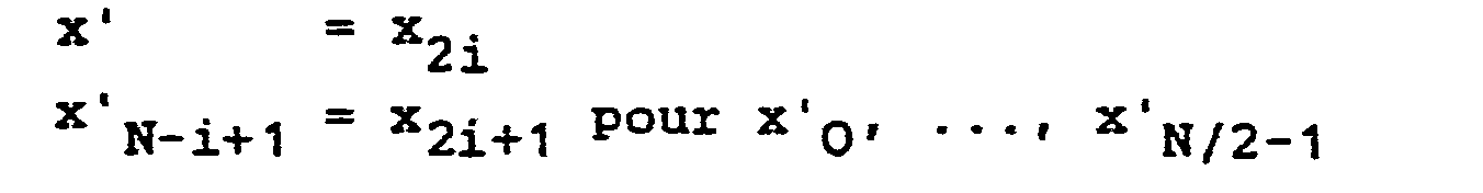
Ce changement de variable distribue les valeurs x' en deux groupes, correspondant l'un aux valeurs paires x2i de x, l'autre aux valeurs impaires x2i+1.This change of variable distributes the values x 'into two groups, one corresponding to the even values x 2i of x, the other to the odd values x 2i + 1 .
On obtient alors :
. Un second changement de variable va ensuite permettre de faire intervenir, dans la définition de la transformée, la différence de deux indices au lieu d'un produit. On arrivera ainsi à la formulation classique (2) de la convolution cyclique, avec son terme hn-1.. A second change of variable will then make it possible to bring into play, in the definition of the transform, the difference of two indices instead of a product. We will thus arrive at the classical formulation (2) of cyclic convolution, with its term h n-1 .
Pour obtenir ce résultat, on fait appel à la correspondance entre l'ensemble des nombres entiers congrus à 1, modulo 4 et inférieurs à Zn+2 et l'ensemble des entiers inférieurs à 2n. On peut en effet écrire :![]()
![]()
On utilisera par la suite, pour faciliter l'écriture des équations, la notation :![]()
![]()
La formule (3) devient alors :


Pour mieux faire apparaître l'équivalence entre TCD et convolution cyclique, on utilisera maintenant une notation polynominale, faisant intervenir une variable muette z permettant de mettre X sous forme d'un polynôme. On définit deux polynômes U et V comportant N termes, chaque terme correspondant à une puissance de z entre O et N-1 :

Xk sera alors le terme constant du produit polynominal de U(z-1) et de Vk(z). En d'autres termes, Xk est le terme constant (correspondant à z0) du produit :
On peut montrer que tous les termes impairs, c'est-à-dire de la forme V2k'+1 (z) appartiennent à une même famille de polynômes décalés les uns des autres d'une puissance de z modulo zN-1. Cela découle des calculs qui précèdent car l'expression (1), lorsqu'elle est écrite pour les valeurs impaires k = 2k'+1, est symétrique en i et k.We can show that all the odd terms, i.e. of the form V 2k '+ 1 (z) belong to the same family of polynomials offset from each other by a power of z modulo z N-1 . This follows from the above calculations because the expression (1), when written for the odd values k = 2k '+ 1, is symmetric in i and k.
Si on connalt V1 on peut donc en déduire toutes les autres valeurs impaires V2k'+1.If we know V 1 we can therefore deduce all the other odd values V 2k '+ 1 .
Pour faciliter les calculs, on introduira maintenant la séquence :
Cette séquence wi peut être calculée une fois pour toutes et mémorisée dans un dispositif de détermination de la TCD.This sequence w i can be calculated once and for all and stored in a device for determining the TCD.
On va maintenant voir que la TCD peut être obtenue par convolution cyclique de la séquence (x.) des échantillons du signal avec la séquence (wi) mémorisée et quelques additions supplémentaires.We will now see that the TCD can be obtained by cyclic convolution of the sequence (x.) Of the signal samples with the sequence (w i ) memorized and some additional additions.
Pour cela, il suffit de remarquer que le polynôme W(z), dont les w sont les coefficients des puissances successives de la variable muette z, s'écrit :
![]()
![]()
Or, on -a indiqué plus haut que tous les termes impairs V2k'+1 appartiennent à une même famille et se déduisent les uns des autres par décalage. Tous les termes impairs V2k'+1 se déduisent donc de V1(z) par décalage. De même, tous les termes pairs V2(2k'+1) (z) se déduisent de V2 par décalage. En effet, on peut remarquer la similitude entre l'expression 2V1(z), donnée par la formule (13), et celle de 2W(N/2) (z) :![]()
![]()
![]()
![]()
Par itération, on obtiendra ainsi successivement :

Exprimé sous une autre forme, on peut présenter Vk(z) sous la forme :
La formule (16) fait apparaître que tous les Vk sont formés par la somme de versions décalées, au sens polynominal (c'est-à-dire découlant les unes des autres par multiplication par z).Formula (16) shows that all V k are formed by the sum of offset versions, in the polynominal sense (that is to say arising from each other by multiplication by z).
La seule connaissance du produit de polynômes Y(z) :
![]()

![]()
Or, le produit de polynômes U(z-1).W(z) est une autre écriture de la convolution cyclique de{ui} par {w-i} =
En résumé, on voit que la TCD peut être obtenue en effectuant en séquence :
- - une opération de convolution cyclique classique faisant intervenir les échantillons d'entrée x et les valeurs w qui peuvent être calculées et mémorisées une fois pour toutes, pour chaque valeur de N ;
- - les opérations représentées par les équations
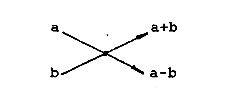
- (15) et (16) qui se limitent à des additions et peuvent être représentées sous la forme des "papillons" intervenant dans les transformées de Fourier, a et b étant les entrées :

- a conventional cyclic convolution operation involving the input samples x and the values w which can be calculated and stored once and for all, for each value of N;
- - the operations represented by the equations
- (15) and (16) which are limited to additions and can be represented in the form of "butterflies" intervening in the Fourier transforms, a and b being the inputs:
La Figure 1 montre, à titre d'exemple, une constitution possible d'un dispositif de transformation en cosinus utilisant un convolueur cyclique pouvant avoir l'une quelconque des constitutions classiques connues. Il peut notamment s'agir d'un convolueur cyclique de type systolique tel que celui décrit dans l'article de H. Barral et autres "Circuits for digital signal processing", Proceedings of ICASSP 84, Paper No. 44-9, complété de connexions pour le rendre cyclique. Le convolueur 10 représenté est prévu pour réaliser une transformée en cosinus de longueur N = 8. Il comporte huit entrées destinées à recevoir les échantillons x0,..., x7 et huit entrées w0,..., w7 destinées à recevoir les valeurs w, mémorisées dans une mémoire morte 12. Les valeurs de sortie y0,..., y7 fournies par le convolueur sont celles données par la formule (19) ci-dessus. Ces valeurs doivent être combinées par des opérateurs qui se limitent à des opérations d'addition ou de soustraction. Un premier jeu d'opérateurs 14 de type "papillon", correspondant à l'algorithme (13) ci-dessus fournit directement le double des valeurs de X 1, X5, x7 et X3 (termes impairs). Un second jeu, 16, constitué de deux opérateurs identiques aux quatre opérateurs 14, fournit, à partir des sorties additives des opérateurs 14, le quadruple de la valeur de X2 et de X6. Enfin, un dernier opérateur 18 fournit l'octuple de la valeur de Xo et de x4.Figure 1 shows, by way of example, a possible constitution of a cosine transformation device using a cyclic convolver which may have any of the known conventional constitutions. It may in particular be a cyclic convolver of the systolic type such as that described in the article by H. Barral and others "Circuits for digital signal processing", Proceedings of ICASSP 84, Paper No. 44-9, supplemented by connections to make it cyclical. The
L'existence d'une équivalence entre TCD et convolution cyclique permet de calculer la complexité multiplicative des TCD de longueur 2n quelconque, c'est-à-dire le nombre minimum de multiplications nécessaire au calcul d'une TCD de longueur 2n. En effet, puisque le passage de la convolution à la TCD ne nécessite pas de multiplication, la TCD et la convolution ont la même complexité multiplicative :![]()
![]()
Au surplus, il faut noter que l'une des multiplications est triviale, c'est-à-dire consiste en une multiplication par un facteur appartenant à l'ensemble des rationnels. En conséquence :![]()
![]()
Dans l'exemple choisi plus haut d'une longueur N = 8 = 23, il sera nécessaire d'effectuer 24 -3 -2 = 11 multiplications.In the example chosen above with a length N = 8 = 2 3 , it will be necessary to carry out 2 4 -3 -2 = 11 multiplications.
Les technologies actuelles courantes permettent d'effectuer une multiplication à une cadence de 10 MHz. Si l'on souhaite réaliser cette même cadence dans des circuits pour répondre par exemple aux besoins des systèmes de photo-videotext, il sera nécessaire d'intégrer dans le circuit au moins deux multiplications, et souvent davantage du fait du manque de régularité des produits.Current current technologies allow multiplication at a rate of 10 MHz. If one wishes to achieve this same rate in circuits to meet for example the needs of photo-videotext systems, it will be necessary to integrate into the circuit at least two multiplications, and often more because of the lack of regularity of the products .
Pour des mots de douze bits en entrée, on peut atteindre, avec un seul convolueur complet du genre décrit ci-dessus, une vitesse de l'ordre de 300 kHz pour des niveaux de douze éléments binaires en entrée.For words of twelve bits at input, one can reach, with a single complete convolver of the kind described above, a speed of the order of 300 kHz for levels of twelve binary elements at input.
Dans la variante de réalisation montrée en Figure 2, le dispositif utilise un transformateur en nombre entier, 20. Les valeurs (Xn) sont appliquées à l'entrée d'un transformateur en nombre entier ou TNE qui fournit une séquence (Ak) :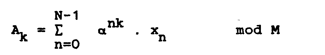
Le dispositif comprend également une mémoire 22 dans laquelle sont stockées les transformées en nombre entier (Bk) de la séquence (wn) de valeur w. Les valeurs Bk sont calculées une fois pour toutes par la formule
Les transformées en nombre entier sont appliquées à un multiplicateur modulo M 24 qui fournit la transformée en nombre entier de la séquence résultat (yn) qui est obtenue à l'aide d'un tranformateur en nombre entier inverse ou TNE 26.The integer transforms are applied to a modulo
En choisissant convenablement N et M, on peut avoir une valeur simple de a. On peut notamment prendre une valeur de a égale à une puissance de 2. Dans ce cas, les transformateurs TNE et TNE-1 ne comportent pas de multiplication, mais uniquement des décalages ce qui simplifie la réalisation matérielle du circuit.By choosing N and M appropriately, we can have a simple value of a. One can in particular take a value of a equal to a power of 2. In this case, the transformers TNE and TNE -1 do not comprise multiplication, but only shifts which simplifies the material realization of the circuit.
De plus, l'utilisation de transformateurs en nombre entier permet une simplification supplémentaire , si l'on tient compte que les réductions de Y(z) = E yn.zn modulo (les polynômes cyclotomiques) interviennent comme variables intermédiaires à l'intérieur des algorithmes de TNE. On peut interrompre le calcul de TNE intervenant en Figure 2 avant son terme.In addition, the use of integer transformers allows an additional simplification, if we take into account that the reductions of Y (z) = E y n .z n modulo (cyclotomic polynomials) intervene as intermediary variables to the inside TNE algorithms. We can interrupt the calculation of TNE occurring in Figure 2 before its term.
La Figure 3 est un graphe d'un dispositif de détermination de transformée en cosinus qui utilise l'algorithme simplifié, pour une longueur N = 8. Sur le graphe apparaissent les groupes d'opérateurs en papillon 28, 30, 32 et 34 ayant la même constitution que ceux utilisés dans la Figure 1. Toutefois, les opérateurs de la Figure 1 sont des opérateurs courants alors que ceux de la Figure 3 fournissent le résultat modulo M et peuvent être du genre décrit dans la demande FR 84 14624. Les multiplieurs B0 à B7 reçoivent, d'une part, la séquence de valeurs fournie par les transformateurs 28 et 30 à partir des valeurs x0,..., x7 et, d'autre part, les valeurs B0,..., B7, TNE des valeurs w correspondantes. Ces valeurs H0,..., B7 peuvent être fournies par une mémoire morte ou déterminées par les multiplieurs eux-mêmes, à partir des valeurs w.FIG. 3 is a graph of a device for determining the cosine transform which uses the simplified algorithm, for a length N = 8. On the graph appear the groups of operators in
Le transformateur de la Figure 3 présente l'avantage de n'exiger qu'une multiplication générale (modulo M) par point. En conséquence, les circuits peuvent être réalisés de façon à fonctionner à une vitesse d'échantillonnage égale à la vitesse de cadence- ment du multiplieur pouvant être de 10 MHz avec les technologies disponibles à l'heure actuelle. En utilisant des schémas de multiplieur particuliers, tels que celui montré en Figure 11 de la demande FR 84 14624, on peut encore augmenter la vitesse.The transformer of Figure 3 has the advantage of requiring only a general multiplication (modulo M) per point. Consequently, the circuits can be constructed so as to operate at a sampling speed equal to the rate of speed of the multiplier which can be 10 MHz with the technologies available at present. By using particular multiplier diagrams, such as that shown in FIG. 11 of application FR 84 14624, the speed can be further increased.
On peut constituer des dispositifs similaires à celui de la Figure 3, mais correspondant à d'autres valeurs de N. Il est particulièrement intéressant, dans tous les cas, d'adopter des valeurs particulières de M qui se traduisent par une simplification de l'architecture. C'est notamment le cas lorsqu'on adopte pour M un nombre de Fermat 22q + 1, un pseudo nombre de Fermat 22q + 1, ou un nombre du type M = 22q - 2q + 1. Par exemple, pour un nombre du dernier type avec q = 12, a = 2 9, toute multiplication par une puissance de a est composée uniquement de rotations, complémentations et, éventuellement, d'une addition.One can constitute devices similar to that of FIG. 3, but corresponding to other values of N. It is particularly interesting, in all cases, to adopt particular values of M which result in a simplification of the architecture. This is particularly the case when adopting for M a number of
Dans une variante de réalisation de l'invention, la transformation en nombres entiers est réalisée en utilisant un changement de base et un codage du type décrit dans la demande de brevet FR 84 14624 (Duhamel et Hollmann). Dans ce cas, le schéma général de la TCD peut se limiter à celui donné en Figure 4.In an alternative embodiment of the invention, the transformation into whole numbers is carried out using a base change and a coding of the type described in patent application FR 84 14624 (Duhamel and Hollmann). In this case, the general diagram of the TCD can be limited to that given in Figure 4.
Le dispositif de la Figure 4 comprend, en amont du transformateur en nombre entier 20, un circuit 36 de codage et de changement de base. La séquence {H} appliquée au multiplieur 24 est également obtenue par codage, changement de base et TNE. La séquence de sortie du multiplieur 24 n'a pas à être soumise à la totalité d'une TNE inverse, puisque les réductions de Y(z) interviennent comme variables intermédiaires. Le calcul est arrêté à ce stade, ce qui permet de simplifier le transformateur TNE 1 38. Les résultats obtenus sont soumis à décodage et retour à la base initiale dans un circuit 40, qui fournit la séquence (Xk).The device of Figure 4 comprises, upstream of the
Les composants 20, 24 et 38 de la Figure 4 peuvent alors être constitués par le montage en traits pleins de la Figure 3, qui devrait normalement être complété par les composants en tirets. Les entrées x. sont appliquées à ce montage après codage en 36 et on obtiendrait sur la sortie les valeurs Nyi codées ; cette partie en tirets n'est pas nécessaire et ce sont les X qui sont appliqués au décodeur 40.The
L'ensemble du circuit de la Figure 3 (y compris la partie en tirets) peut constituer un convolueur 10 utilisable dans le dispositif de la Figure 1.The entire circuit of Figure 3 (including the dashed part) can constitute a
Les constitutions de convolueur mentionnées ci-dessus ne sont pas les seules possibles. On peut en particulier utiliser un convolueur utilisant des circuits mettant en oeuvre une arithmétique distribuée, telle que celle décrite dans "Digital Filter Structures Described by Distributed Arithmetic", C. Sydney Burrus, IEEE Transactions on circuits and systems, cas. 24, No. 12, Dec. 77, pp. 674-680 et dans "A Prime Factor FTT Algorithm Using Distributed Arithmetic" par Shuni Chu et al, IEEE Transactions on Acoustics, Speech and signal processing, Vol. ASSP-30, No. 2, Avril 82, pp. 217-226.The convolution constitutions mentioned above are not the only ones possible. One can in particular use a convolver using circuits implementing a distributed arithmetic, such as that described in "Digital Filter Structures Described by Distributed Arithmetic", C. Sydney Burrus, IEEE Transactions on circuits and systems, case. 24, No. 12, Dec. 77, pp. 674-680 and in "A Prime Factor FTT Algorithm Using Distributed Arithmetic" by Shuni Chu et al, IEEE Transactions on Acoustics, Speech and signal processing, Vol. ASSP-30, No. 2, April 82, pp. 217-226.
Claims (3)


Applications Claiming Priority (2)
| Application Number | Priority Date | Filing Date | Title |
|---|---|---|---|
| FR8601629A FR2593948B1 (en) | 1986-02-06 | 1986-02-06 | DEVICE FOR TRANSFORMING A COSANUS OF A SAMPLE DIGITAL SIGNAL |
| FR8601629 | 1986-02-06 |
Publications (2)
| Publication Number | Publication Date |
|---|---|
| EP0237382A1 true EP0237382A1 (en) | 1987-09-16 |
| EP0237382B1 EP0237382B1 (en) | 1992-12-16 |
Family
ID=9331864
Family Applications (1)
| Application Number | Title | Priority Date | Filing Date |
|---|---|---|---|
| EP87400278A Expired - Lifetime EP0237382B1 (en) | 1986-02-06 | 1987-02-06 | Digital sampled signal cosine transforming device |
Country Status (5)
| Country | Link |
|---|---|
| US (1) | US4797847A (en) |
| EP (1) | EP0237382B1 (en) |
| JP (1) | JPS62235622A (en) |
| DE (1) | DE3783056T2 (en) |
| FR (1) | FR2593948B1 (en) |
Families Citing this family (11)
| Publication number | Priority date | Publication date | Assignee | Title |
|---|---|---|---|---|
| US5053985A (en) * | 1989-10-19 | 1991-10-01 | Zoran Corporation | Recycling dct/idct integrated circuit apparatus using a single multiplier/accumulator and a single random access memory |
| US4974078A (en) * | 1989-11-13 | 1990-11-27 | Eastman Kodak Company | Digital compression method and system with improved coding efficiency |
| US5349549A (en) * | 1991-09-30 | 1994-09-20 | Sony Corporation | Forward transform processing apparatus and inverse processing apparatus for modified discrete cosine transforms, and method of performing spectral and temporal analyses including simplified forward and inverse orthogonal transform processing |
| US5339265A (en) * | 1992-08-31 | 1994-08-16 | University Of Maryland At College Park | Optimal unified architectures for the real-time computation of time-recursive discrete sinusoidal transforms |
| US5523847A (en) * | 1992-10-09 | 1996-06-04 | International Business Machines Corporation | Digital image processor for color image compression |
| KR950010740B1 (en) * | 1992-12-30 | 1995-09-22 | 엘지전자주식회사 | Transform coding method and apparatus of image system |
| FR2702612B1 (en) * | 1993-03-10 | 1995-06-09 | France Telecom | METHOD AND DEVICE FOR FILTERING A DIGITAL TIME SIGNAL, AND APPLICATION TO CORRECTING ECHOS IN A TRANSMISSION CHANNEL. |
| US5408425A (en) * | 1993-05-25 | 1995-04-18 | The Aerospace Corporation | Split-radix discrete cosine transform |
| US5719795A (en) * | 1995-07-26 | 1998-02-17 | Westvaco Corporation | Method to provide consistent estimated growth and yield values for loblolly pine plantations |
| US6871208B1 (en) * | 1999-12-01 | 2005-03-22 | Macronix International Co., Ltd. | Parallel adder-based DCT/IDCT design using cyclic convolution |
| SG11201909441XA (en) * | 2017-04-11 | 2020-03-30 | Governing Council Univ Toronto | A homomorphic processing unit (hpu) for accelerating secure computations under homomorphic encryption |
Citations (1)
| Publication number | Priority date | Publication date | Assignee | Title |
|---|---|---|---|---|
| US4385363A (en) * | 1978-12-15 | 1983-05-24 | Compression Labs, Inc. | Discrete cosine transformer |
Family Cites Families (5)
| Publication number | Priority date | Publication date | Assignee | Title |
|---|---|---|---|---|
| US4152772A (en) * | 1974-08-29 | 1979-05-01 | The United States Of America As Represented By The Secretary Of The Navy | Apparatus for performing a discrete cosine transform of an input signal |
| US3920974A (en) * | 1974-10-15 | 1975-11-18 | Us Navy | Discrete cosine transform signal processor |
| US4196448A (en) * | 1978-05-15 | 1980-04-01 | The United States Of America As Represented By The Secretary Of The Navy | TV bandwidth reduction system using a hybrid discrete cosine DPCM |
| US4449194A (en) * | 1981-09-25 | 1984-05-15 | Motorola Inc. | Multiple point, discrete cosine processor |
| FR2561010B1 (en) * | 1984-03-09 | 1986-09-12 | Cit Alcatel | PROCESSOR FOR CALCULATING A DISCRETE COSINUS TRANSFORM |
-
1986
- 1986-02-06 FR FR8601629A patent/FR2593948B1/en not_active Expired
-
1987
- 1987-02-04 US US07/010,702 patent/US4797847A/en not_active Expired - Fee Related
- 1987-02-06 EP EP87400278A patent/EP0237382B1/en not_active Expired - Lifetime
- 1987-02-06 DE DE8787400278T patent/DE3783056T2/en not_active Expired - Fee Related
- 1987-02-06 JP JP62024926A patent/JPS62235622A/en active Pending
Patent Citations (1)
| Publication number | Priority date | Publication date | Assignee | Title |
|---|---|---|---|---|
| US4385363A (en) * | 1978-12-15 | 1983-05-24 | Compression Labs, Inc. | Discrete cosine transformer |
Non-Patent Citations (1)
| Title |
|---|
| IEEE TRANSACTIONS ON ACOUSTICS, SPEECH, AND SIGNAL PROCESSING, vol. ASSP-28, no. 1, février 1980, pages 27-34, IEEE, New York, US; J. MAKHOUL: "A fast cosine transform in one and two dimensions" * |
Also Published As
| Publication number | Publication date |
|---|---|
| JPS62235622A (en) | 1987-10-15 |
| FR2593948A1 (en) | 1987-08-07 |
| DE3783056D1 (en) | 1993-01-28 |
| US4797847A (en) | 1989-01-10 |
| FR2593948B1 (en) | 1989-10-27 |
| EP0237382B1 (en) | 1992-12-16 |
| DE3783056T2 (en) | 1993-04-15 |
Similar Documents
| Publication | Publication Date | Title |
|---|---|---|
| FR2788867A1 (en) | Arithmetic method and implementation for cryptographic processing | |
| FR2867579A1 (en) | Montgomery modular multiplier for computing system, selects one of n-bit modulus numbers as a modulus product and one of n-bit multiplicand numbers as partial product | |
| FR2587819A1 (en) | DEVICE FOR CALCULATING A DISCRETE, SLIDING, NON-RECURSIVE FOURIER TRANSFORMATION AND APPLICATION THEREOF TO A RADAR SYSTEM | |
| FR2740284A1 (en) | WIDE BAND DIGITAL FILTERING METHOD AND FILTER USING THE METHOD | |
| EP0237382B1 (en) | Digital sampled signal cosine transforming device | |
| EP2515228A1 (en) | Montgomery multiplication method | |
| EP1190344B1 (en) | Complex number multiplier | |
| EP0207859B1 (en) | Discrete and shifting fourier transform calculating device, for using in a radar system | |
| FR2588680A1 (en) | DEVICE FOR CALCULATING A DISCRETE FOURIER TRANSFORMER, AND ITS APPLICATION TO PULSE COMPRESSION IN A RADAR SYSTEM | |
| FR2675969A1 (en) | METHOD AND DEVICE FOR ENCODING-DECODING A DIGITAL SIGNAL | |
| EP0171305B1 (en) | Calculation circuit for the discrete fourier transform | |
| EP0262032B1 (en) | Binary adder having a fixed operand, and a parallel/serial multiplier comprising such an adder | |
| EP0703528B1 (en) | Electronic circuit for modulo computation in a finite field | |
| EP0022513B1 (en) | Device for calculating a bidimensional discrete fourier transform | |
| EP0437876A1 (en) | Programmable serial multiplier | |
| EP0242258B1 (en) | Device for the execution of an algorithm (leroux-gueguen) for the coding of a signal by linear prediction | |
| EP0320352B1 (en) | Numeric computation integrated circuit for convolution-like computations | |
| EP1071008A1 (en) | Method for performing multiplication with accumulation in a Galois field | |
| EP0175623A1 (en) | Device for the real-time processing of a digital signal by convolution | |
| EP0285495B1 (en) | Digital signal processing system using a filter bank | |
| FR2536541A1 (en) | Simplified spectral analysis system using phases | |
| EP1335277B1 (en) | Efficient saturating operation | |
| CA2359198C (en) | Arithmetic unit for carrying out a cryptographic protocol | |
| EP0241352A1 (en) | Circuit for performing a linear transformation on a digital signal | |
| EP0718755B1 (en) | Electronic component, more particularly capable of performing a radix 4 division of two numbers |
Legal Events
| Date | Code | Title | Description |
|---|---|---|---|
| PUAI | Public reference made under article 153(3) epc to a published international application that has entered the european phase |
Free format text: ORIGINAL CODE: 0009012 |
|
| AK | Designated contracting states |
Kind code of ref document: A1 Designated state(s): DE GB NL |
|
| 17P | Request for examination filed |
Effective date: 19880206 |
|
| 17Q | First examination report despatched |
Effective date: 19900119 |
|
| RAP1 | Party data changed (applicant data changed or rights of an application transferred) |
Owner name: FRANCE TELECOM |
|
| GRAA | (expected) grant |
Free format text: ORIGINAL CODE: 0009210 |
|
| AK | Designated contracting states |
Kind code of ref document: B1 Designated state(s): DE GB NL |
|
| PG25 | Lapsed in a contracting state [announced via postgrant information from national office to epo] |
Ref country code: NL Effective date: 19921216 |
|
| GBT | Gb: translation of ep patent filed (gb section 77(6)(a)/1977) |
Effective date: 19921215 |
|
| REF | Corresponds to: |
Ref document number: 3783056 Country of ref document: DE Date of ref document: 19930128 |
|
| NLV1 | Nl: lapsed or annulled due to failure to fulfill the requirements of art. 29p and 29m of the patents act | ||
| PLBE | No opposition filed within time limit |
Free format text: ORIGINAL CODE: 0009261 |
|
| STAA | Information on the status of an ep patent application or granted ep patent |
Free format text: STATUS: NO OPPOSITION FILED WITHIN TIME LIMIT |
|
| 26N | No opposition filed | ||
| PGFP | Annual fee paid to national office [announced via postgrant information from national office to epo] |
Ref country code: GB Payment date: 19940201 Year of fee payment: 8 |
|
| PGFP | Annual fee paid to national office [announced via postgrant information from national office to epo] |
Ref country code: DE Payment date: 19940222 Year of fee payment: 8 |
|
| PG25 | Lapsed in a contracting state [announced via postgrant information from national office to epo] |
Ref country code: GB Effective date: 19950206 |
|
| GBPC | Gb: european patent ceased through non-payment of renewal fee |
Effective date: 19950206 |
|
| PG25 | Lapsed in a contracting state [announced via postgrant information from national office to epo] |
Ref country code: DE Effective date: 19951101 |