EP0227326A2 - Optical fiber communications cable - Google Patents

Optical fiber communications cable Download PDF

Info

Publication number
EP0227326A2
EP0227326A2 EP86309299A EP86309299A EP0227326A2 EP 0227326 A2 EP0227326 A2 EP 0227326A2 EP 86309299 A EP86309299 A EP 86309299A EP 86309299 A EP86309299 A EP 86309299A EP 0227326 A2 EP0227326 A2 EP 0227326A2
Authority
EP
European Patent Office
Prior art keywords
jacket
cable
strength
optical fiber
strength members
Prior art date
Legal status (The legal status is an assumption and is not a legal conclusion. Google has not performed a legal analysis and makes no representation as to the accuracy of the status listed.)
Withdrawn
Application number
EP86309299A
Other languages
German (de)
French (fr)
Other versions
EP0227326A3 (en
Inventor
Brian Dennis Johnson
William Cogel Reed
Carla Green Wilson
Current Assignee (The listed assignees may be inaccurate. Google has not performed a legal analysis and makes no representation or warranty as to the accuracy of the list.)
AT&T Corp
Original Assignee
American Telephone and Telegraph Co Inc
AT&T Corp
Priority date (The priority date is an assumption and is not a legal conclusion. Google has not performed a legal analysis and makes no representation as to the accuracy of the date listed.)
Filing date
Publication date
Application filed by American Telephone and Telegraph Co Inc, AT&T Corp filed Critical American Telephone and Telegraph Co Inc
Publication of EP0227326A2 publication Critical patent/EP0227326A2/en
Publication of EP0227326A3 publication Critical patent/EP0227326A3/en
Withdrawn legal-status Critical Current

Links

Images

Classifications

    • HELECTRICITY
    • H01ELECTRIC ELEMENTS
    • H01BCABLES; CONDUCTORS; INSULATORS; SELECTION OF MATERIALS FOR THEIR CONDUCTIVE, INSULATING OR DIELECTRIC PROPERTIES
    • H01B11/00Communication cables or conductors
    • GPHYSICS
    • G02OPTICS
    • G02BOPTICAL ELEMENTS, SYSTEMS OR APPARATUS
    • G02B6/00Light guides; Structural details of arrangements comprising light guides and other optical elements, e.g. couplings
    • G02B6/44Mechanical structures for providing tensile strength and external protection for fibres, e.g. optical transmission cables
    • G02B6/4401Optical cables
    • G02B6/4429Means specially adapted for strengthening or protecting the cables
    • G02B6/443Protective covering
    • GPHYSICS
    • G02OPTICS
    • G02BOPTICAL ELEMENTS, SYSTEMS OR APPARATUS
    • G02B6/00Light guides; Structural details of arrangements comprising light guides and other optical elements, e.g. couplings
    • G02B6/44Mechanical structures for providing tensile strength and external protection for fibres, e.g. optical transmission cables
    • G02B6/4401Optical cables
    • G02B6/4429Means specially adapted for strengthening or protecting the cables
    • G02B6/443Protective covering
    • G02B6/4432Protective covering with fibre reinforcements
    • GPHYSICS
    • G02OPTICS
    • G02BOPTICAL ELEMENTS, SYSTEMS OR APPARATUS
    • G02B6/00Light guides; Structural details of arrangements comprising light guides and other optical elements, e.g. couplings
    • G02B6/44Mechanical structures for providing tensile strength and external protection for fibres, e.g. optical transmission cables
    • G02B6/4401Optical cables
    • G02B6/4429Means specially adapted for strengthening or protecting the cables
    • G02B6/4436Heat resistant

Abstract

An optical fiber cable includes a first jacket (15), typically comprising a polyvinyl chloride material, a core member (11) comprising at least one, typically ≦ l0, optical fiber(s) (13), and a core wrap (12) loosely surrounding the optical fiber(s). The optical fiber(s) typically is (are) slightly overstuffed. The cable further comprises three non-metallic strength members (16) (or groups of strength members) completely embedded in the first jacket and coupled thereto. In cables containing three strength members, the coupling is typically characterized by a pull-out strength of at least 50, preferably more than 80 lbs/in per strength member. Each strength member comprises a multiplicity of impregnated filaments, preferably borosilicate glass filaments impregnated with a urethane. The preferred cable typically has a circularly symmetric cross section, with the three strength members, each of radius r<sub>s</sub>, disposed longitudinally, their axes a distance R from the axis of the first jacket,with R-r<sub>s</sub> > l.l55r, where r is the inner radius of the first jacket. In one embodiment of the invention, the voids between the optical fiber(s) and the core wrap is filled with a filling compound, e.g., a fire retardant grease composition. In another embodiment, the cable further comprises a metal member, e.g., a steel tape, that contactingly surrounds the first jacket, and a plastic, e.g., polyvinyl chloride, outer jacket that contactingly surrounds the metal member. The cable can advantageously be used in the local distribution network, including in external plant applications such as distribution or buried service cable, and indoor applications such as riser or plenum cable.

Description

    Background of the Invention
  • Optical fiber is finding increasing application in long-haul signal transmission, and many cable designs have been proposed or are available commercially. See, for instance, U. S. Patents 4,078,853 and 4,24l,979.
  • Recently it has become apparent that optical fiber not only can advantageously be used as a long-haul (e.g., inter-city) transmission medium but potentially can also be used economically in the local distribution network (exemplarily including distribution, service or drop, and indoor cable) , thus opening the possibility of end-to-end optical communications. However, the optical fiber cables that were designed for long-haul applications are typically not well suited for use in the local distribution network. For instance, such cables typically are designed to have medium to high fiber count
    (> l0 fibers) , are frequently relatively rigid and have a relatively large bending radius, and tend to be relatively costly to manufacture. On the other hand, cable for use in the local distribution plant typically requires only low fiber count (e.g.,≦ l0 fibers), should be flexible, have a small bending radius, be usable in a variety of environments, be deployable by existing means e.g., by means of vibratory plough or by trenching, and advantageously be easy to manufacture.
  • The prior art does know several optical fiber cables that are designed for use in the local distribution network. For instance, S. Kukita et al, Review of the Electrical Communications Laboratories, Volume 32(4), pp. 636-645 (l984) review the design and performance of optical drop and indoor cables, and disclose, inter alia, an indoor cable comprising a coated fiber surrounded by a PVC sheath, with four steel wires embedded in the sheath. Such a design can be expected to have some shortcomings, including a need for electrically grounding the steel wires, and difficulty in achieving good coupling between the sheath and the steel wires, and may cause bending-induced stresses on the optical fiber.
  • An exemplary commercially available optical fiber cable that can find use in local distribution plant comprises a central (steel or polymer) strength member surrounded by a polyurethane jacket, a multiplicity of fiber-containing loose tubes stranded around the polyurethane jacket, polyester tape and a polyethylene inner jacket surrounding the tubes, and steel or Al armor and a polyethylene outer jacket surrounding the inner jacket. In such a structure the fibers cannot be on the neutral axis of the cable when the cable is bent, requiring stranding of the loose tubes, which in turn complicates manufacture. Furthermore, in such a design the strength member is not well coupled to the outside jacket.
  • Another commercially available optical fiber cable for use in the local distribution network has a core consisting of a central coated steel wire strength member and a multiplicity of polymer tubes arranged around the central strength member, each tube containing one buffered optical fiber as well as a moisture resistant filling compound. This core is surrounded by aramid yarn which is said to take up the greater part of any tensile load applied to the fiber. The yarn layer in turn is surrounded by a polyethylene jacket. Thus constituted cables are said to be useful as aerial or duct cable. In cable for direct burial, a polyurethane inner jacket takes the place of above referred to polyethylene jacket, and steel tape armoring and a polyethylene outer jacket surround the inner jacket.
  • In this cable structure too, the fibers cannot be on the neutral axis of the cable when the cable is bent, thus also requiring stranding of the loose tubes. Furthermore, axial stresses are poorly coupled from the outer surface of the cable to the central strength member.
  • Still another family of commercially available optical fiber cables for use in the local distribution network contains cables of the "loose tube" type in which one or more optical fibers are loosely surrounded by a polyethylene or PVC jacket, the voids within the thus formed loose tube being filled with polymeric gel. Two aramid fiber or steel strength members are embedded in the jacket, thereby defining the neutral plane for bending. The cables are available with flame retardant jackets.
  • Among the drawbacks of such a design is the fact that bending of the cable will frequently cause it to undergo a substantial amount of twist. Furthermore, it is expected that in this design fibers and filling compound are exposed to relatively high temperatures during cable manufacture. In such a design, it may occur that vinyl-buffered fibers (a currently frequently used fiber type) may fuse to the PVC jackets.
  • In view of the desirability of the ability to provide an optical fiber transmission path onto customer premises, an optical fiber cable that can be easily adapted for indoor (including flame retardant, riser and plenum cable) as well as for outdoor use (drop cable or distribution cable, unarmored or armored, including rodent-resistantly armored), that is of small diameter, highly flexible, crush resistant as well as resistant to tensile loading, that can be terminated easily and conveniently, and that is easy to manufacture, would be of considerable interest. This application discloses such an optical fiber cable.
  • Summary of the Invention
  • The optical fiber communications transmission cable according to the invention comprises a core member, a first jacket surrounding the core member, and three groups of non-metallic strength members (each "group" comprising one or more strength members) completely embedded in the first jacket and coupled thereto.
  • The optical fiber cable is basically of the "loose tube" type, with the core member comprising a first member, typically a core wrap, preferably impregnated woven fiberglass, that loosely surrounds one, two, or more, typically no more than l0, optical fibers. For some applications of tbe cable, the voids between the optical fiber(s) and the core wrap are substantially filled with a filling compound. For indoor use the cable advantageously contains only flame retardant materials. The optical fiber(s) typically are "overstuffed", i.e., in any length lc of cable, the length lg of any optical fiber in the cable is greater than lc by some small amount.
  • The core member is surrounded by the first jacket, with the jacket typically not being coupled to the core member to a substantial degree. The longitudinal axis of the first jacket typically substantially coincides with the longitudinal axis of the core member, and the first jacket preferably has substantially circular cross section. Each one of the strength members embedded in the first jacket includes a multiplicity of filaments that are assembled together to form a roving or yarn, the filaments having been impregnated with a material that is compatible with that of the first jacket, resulting in substantial coupling between the first jacket and the strength members embedded therein.
  • The strength members are disposed in a generally longitudinal direction between the core member and the outer surface of the first jacket, substantially equidistant from, and symmetrical with respect to, the axis of the first jacket. Use of three strength members (or groups of strength members) disposed around the core member results in particularly advantageous cable characteristics. For instance, if the cable is bent, there will always be two strength members (or group thereof) in tension and one in compression. This results in a reduction of tensile strength in the bent configuration by only l/3, as compared to l/2 (or nearly l/2) for four or more unstranded strength members (or groups thereof) . Furthermore, the geometry of the inventive cable assures that any tensile fiber strain will always be less than the tensile strain of the stress members that are under tension.
  • The inventive cable can further comprise metallic (e.g., stainless steel) armoring surrounding the first jacket, surrounded by a polymer outer jacket. In this embodiment the invention is suitable for deployment by plowing, trenching, pulling into conduits, or other mechanical methods. The armoring can, for instance, be longitudinally applied corrugated plain or Cu-clad stainless steel strip, or helically applied flat plain or Cu-clad stainless steel tape. The outer jacket and the armoring are advantageously applied such that they are mechanically coupled to the first jacket. This assures that longitudinal stresses that act on the outer surface of the outer jacket are transmitted to, and substantially borne by, the stress members.
  • Brief Description of the Drawings
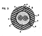
  • FIGS. l, 2 and 3 show, in cross section, exemplary cables according to the invention.
  • Detailed Description of the Preferred Embodiment
  • In FIG. l is shown a cable l0 according to the invention, comprising a core member ll that contains two optical fibers l3. The fibers can be of any desired fiber type, multimode or single mode, buffered or unbuffered, glass or plastic, silica-based or nonsilica-based glass lightguide. Currently, polymer coated silica-based multimode and single mode fibers are widely used in optical fiber telecommunications, and a currently preferred embodiment of the invention contains two coated and buffered silica-based fibers. Such fibers are well known and require no detailed discussion.
  • The fibers are loosely surrounded by core wrap l2, exemplarily a longitudinally disposed strip of woven fiber glass. In a preferred embodiment, the woven strip is impregnated with a polymer, e.g., polytetrafluoroethylene. The core wrap loosely surrounds the fibers such that the long sides of the core wrap strip overlap, thereby completely enclosing the fibers.
  • In some embodiments of the invention, the voids between the fibers and the core wrap are substantially filled with a fiber optical filling compound, e.g., a fire retardant grease composition consisting of about 5% by weight of hydrophobic fumed silica and about 95% by weight of a chlorinated paraffin oil. The filling compound leaves the fibers substantially free to move under applied stresses. In preferred embodiments, the filling compound advantageously fills essentially all voids within the core wrap, thereby serving to exclude water from the core.
  • The core member ll is contactingly surrounded by a first jacket l5. The first jacket comprises plastic material which, in a preferred embodiment, comprises polyvinyl chloride (PVC). For at least some applications of the inventive cable, it is desirable that the PVC be semi-rigid, so as to result in a structure having a relatively high resistance to radial compression. The first jacket cross section typically has circular symmetry, with the longitudinal axis of the first jacket substantially coinciding with the longitudinal axis of the core member.
  • Embedded in first jacket l5 are three non-­metallic strength members l6. Although embodiments with three strength members are particularly advantageous and are preferred, the invention is not so limited. Thus, in general, cable according to the invention contains three groups of strength members, each "group" comprising l, 2, 3, or even more individual spaced-apart strength members, as exemplified in FIG. 3. Each strength member l6 comprises a fibrous strand material which is impregnated with a polymeric material, in the form of a plurality of filaments which are gathered together into one or more rovings or yarns. The filaments may comprise an inorganic material such as fiberglass or an organic material such as KEVLAR aramid fiber. In a preferred embodiment, the strength members l6 are comprised of a plurality of E-glass fibers. E-glass fibers comprise a borosilicate glass composition, with the fibers having a minimum tensile strength of 200,000 psi. In an exemplary preferred embodiment, each strength member comprises 2 rovings, each roving comprising about 2,000 fibers. Although the strength member cross section will frequently be substantially circular, we also envisage non-circular, e.g., ribbon-like, strength members.
  • Optical fiber cable of the type discussed herein may be subjected to substantial tensile forces during deployment and/or during service. Since optical fibers generally can sustain only limited tensile loads before breaking, and since their optical loss increases with strain, it is an object of the invention to provide a cable design in which the fibers are substantially decoupled from tensile stresses applied to the outside of the cable. Aspects of the invention that contribute to achievement of this objective are the presence of substantial coupling between the first jacket and the strength members embedded therein, and low coupling between the first jacket and the core wrap.
  • Not only must the strength members l6 be suitably adhered to the first jacket l5, they must also have suitable strength characteristics to prevent failure under load. Load failure (e.g., in riser cable, or during placement of buried cable) is caused by filament abrasion, flaws and tensile load imbalance. Filaments can be abraded by neighboring filaments in the strength member and by particles in the jacket l5. Uneven sharing of the tensile load results when the filaments are not coupled to share tensile loads evenly. As some filaments break, others accept the load until the total cross section of the strength member fails.
  • Coupling of the strength members to the first jacket, and resistance to failure of the strength members under load, are both enhanced by suitable impregnation of the filaments. Thus, in inventive cables the strength members typically are impregnated with a material that promotes coupling to the jacket l5, that exhibits a relatively high coefficient of static friction with the material of the jacket l5, and that, furthermore, is hydrolytically stable. The impregnating material may be formed either by condensation or addition polymerization reactions and may include, for example, urethanes, acrylic acid or acrylate-based materials, epoxies, polyesters, and polyvinyl chloride or other vinyl based materials. For strength member materials such as fiberglass, a sizing such as silane must be used to protect the filament and to couple the impregnating material to the filament. For materials such as KEVLAR aramid fiber, a sizing may not be required. However, aramid fibers may require a coating to prevent fraying during extrusion, and to enhance coupling to the first jacket.
  • Fiberglass impregnation is customarily accomplished by fiberglass suppliers. Glass filaments are drawn from a furnace bushing and cooled by a water spray followed by the application of a water dispersion of silane. Drying removes excess water and alcohol, which is formed as the silane bonds to glass, and leaves a silane-coated filament with functional groups positioned to couple with a vinyl-compatible impregnating material. Each strength member is impregnated in a bath, with the sized fibers being spaced apart to enhance the impregnation. For an example of a method of impregnating a bundle of filaments, see U. S. Patent 4,479,984.
  • In a preferred embodiment, vinyl compatible, impregnated fiberglass rovings or yarns are used as strength members. The impregnating material, a urethane, couples each silane-coated filament with its neighbors and thus protects the filament against abrasion, bridges flaws, and acts to establish tensile load balance. In the preferred embodiment of the invention a combination of impregnated E-glass fibers/PVC first jacket material is used that has a pull-out strength of more than 80 lbs/in, typically about l00 lbs/in, as determined in a test that will be specified below. We consider that a thus determined pull-out strength of 50 lbs/in in many cases will correspond to the lower limit of coupling strength useful in cable according to the invention.
  • The pull-out test used to quantify the coupling strength corresponds substantially to a standard test method for testing the adhesion of rubber to single-strand wire, which is designated ASTMD-l87l, Procedure A.
  • The test blocks of first jacket material, typically a thermoplastic such as PVC, are to be prepared as follows:
    • a) The starting material (granules, pellets, etc.) is homogenized , a clean 6"×6"×l/4" mold charged with the homogenized material, a molding pressure of 300 psi applied to the mold, the charge heated to l80°C, the temperature maintained for 2-5 minutes, and the material cooled to 70°C at a rate of about 7.5°C/min while applying a pressure of 600 psi to the mold. After cooling to about 30°C the molded sheet of first jacket material is removed from the mold, washed in running warm water and dried with a soft, clean cloth.
    • b) The thus formed sheet is cut into two 6"×2"×l/4" and three 2"×2"×l/4" pieces, one large and one small piece is placed into the bottom of a mold per ASTMD-l87l, Procedure A, l5 samples of the strength member to be tested are inserted in the beveled slots in the mold, and the remaining large and one small piece of the molded material are placed into the mold so as to cover the strength members.
    • c) The thus prepared mold is placed in a preheated press (l70-l80°C), the temperature maintained and a pressure of 850-ll50 psi applied for 2-5 minutes, then the mold cooled, at a rate of at least 22°C/min, to 70°C while maintaining the pressure, followed by cooling to room temperature under ambient pressure.
    • d) The thus prepared block assembly is then tested in accordance with Method A of ASTMD-l87l, using a cross head speed of 2"/min, with the following exception: slots l and l5 are used to set up the pull testing equipment, and their pull-out values are not used. Of the remaining l3 slots, twelve are pulled, the l3th to be used as a spare if needed. Of the twelve pull-out values obtained, the highest and lowest are discarded and the remaining l0 are averaged. The thus obtained value, after normalization, corresponds to the "pull-out strength", as the term is used herein.
  • A significant aspect of preferred embodiments of the invention is the number and placement of strength members l6. In particular, we have found that the use of three strength members, (or three groups of strength members) offers advantages that we consider unobtainable with any other number of strength members (or groups of strength members) . For reasons of, inter alia, simplicity of manufacture, we currently most prefer cables containing three strength members only. The following remarks are intended to apply, however, in analogous fashion also to containing three groups of strength members, each containing two or more strength members. Among the above referred to advantages are the resulting flexibility of the cable structure, and maintenance of the fibers in a relatively stress-free condition even for bend radii as small as one inch. The three strength members are arranged symmetrically with respect to the first jacket axis, i.e., such that the centers of the strength members (having radii rs) are substantially located on the circumference of an imaginary circle (of radius R) centered on the first jacket axis, with the strength members disposed substantially symmetrically (i.e., spaced l20° apart) on this circumference. Furthermore, in preferred embodiments the radius R of the above referred to imaginary circle bears a predetermined relationship to the inner radius (r) of the first jacket. In particular, (R-rs) > r/cos30°, i.e., (R-rs) > l.l55r. If this condition is met then, regardless of the direction in which a cable according to the invention is bent, it typically will arrange itself such that two of the strength members are in tension and the remaining strength member is in compression, with essentially no stress resulting on the core member, thereby avoiding the deformation of the fiber-containing cavity at the center of the cable. Furthermore, the neutral axis of the bent cable will go through the fiber-containing cavity, thereby permitting the fibers to move such as to be always on, or close to, the neutral axis.
  • Although in currently preferred embodiments of the inventive cable the fibers within the core member and the strength members are to be substantially layless (i.e., not stranded), and the strength members are also substantially untwisted, these conditions are not requirements, and we envisage at least under some circumstances the use of twisted strength members, and/or slightly stranded strength members and/or optical fibers.
  • In preferred embodiments of the inventive cable, the fibers contained in the core are overstuffed. By this we mean that, for any length of cable, the length of any one of the fibers contained within the core wrap is greater than the length of the cable. As will be appreciated by those skilled in the art, the amount of overstuffing should be selected such that, for any given cable design, the cable strain under maximum permissible tensile load results in less than maximum permissible fiber strain. A further consideration in the selection of the desired degree of overstuff is the introduction of microbending loss due to fiber undulation. Fiber undulation is the natural consequence of overstuffing, with the undulatory wavelength decreasing with increasing overstuffing. Since susceptibility to microbending loss is a function of fiber design, no general upper limit of permissible overstuffing can be given. However, at least for one commercially available fiber, it was determined that 0.5% overstuffing does not lead to unacceptable microbending loss.
  • A further microbending-related consideration is the choice of core member diameter or, more precisely, the diameter of the volume available to the fibers within the core. In particular, choice of a small core member diameter results in relatively short undulation length, which in turn may result in increased microbending loss, as compared to microbending loss observed in cables with larger core diameter.
  • Although FIG. l shows a cable with two optical fibers in the core, it will be appreciated that the same cable design can be used with one optical fiber, or with any desired number of optical fibers greater than one, limited only by the number of fibers that can be fit into the available space without introducing unacceptable loss, while still permitting the fibers to accommodate to applied stress. For instance, for distribution and building riser cable applications, it may be desirable to have a larger number of fibers present, possibly 4, 8 or l0 fibers. On the other hand, for use as service lightguide or on customer premises, a single fiber, e.g., one single mode fiber, is expected to be sufficient in many cases. It will also be understood that although FIG. l shows buffered fibers, this is not required and unbuffered fibers, i.e., fibers carrying only the usual polymer coating, can also be used. Furthermore, although FIG. l shows a cable with a filled core, core filling is not a requirement, and unfilled cable according to the invention can be used, for instance, in building applications, such as riser cable or plenum.
  • Cable of the type shown in FIG. l can advantageously be used in building applications, be buried directly, or placed into conduits. It is a dielectric structure and therefore immune to lightning strike. On the other hand, it is not protected against rodents or digging equipment.
  • FIG. 2 shows an embodiment of the invention that is protected against mechanical damage, and thus can be used in applications where the previously described embodiment may not be appropriate. The armored cable 20 comprises fibers, a core member, a jacket, and a multiplicity of strength members, all as described above. In addition, 20 comprises metallic armor 2l and outer jacket 22. The armor can be one of several known types of armor. In particular, it can be either a longitudinally applied stainless steel or copper clad stainless steel corrugated tape that is applied overlappingly, or it can be helically applied stainless steel or copper clad stainless steel tape, also applied overlappingly. The former is suitable in cases where protection against damage from digging equipment is required, whereas the latter also provides protection against rodent attack. The outer jacket 22 typically comprises polymer material such as PVC, polyethylene, or polypropylene, with PVC being currently preferred,
  • In preferred embodiments, the armor and outer jacket are applied such that the outer jacket is frictionally coupled to the armor, and the armor in turn is frictionally coupled to the first jacket l5. This can be achieved by known methods. For instance, substantial frictional coupling of the outer jacket to the armor can be achieved by pressure extrusion of the outer jacket material.

Claims (18)

1. A communications transmission cable comprising
a) a core member having a longitudinal axis and comprising at least one optical fiber and first means surrounding the fiber;
b) a first jacket having a longitudinal axis and an inner and an outer surface and comprising a polymeric material, the first jacket enclosing the core member and being substantially coaxial with the core member; and
c) three groups of non-metallic strength members, disposed between the inner and the outer first jacket surfaces in a generally longitudinal direction, each group of strength members comprising one or more strength members and having a longitudinal axis, the longitudinal axis of each group of strength members being a distance R from the first jacket longitudinal axis and being spaced substantially l20°C from the longitudinal axis of each of the remaining two groups, each strength member comprising a plurality of filaments that are gathered together, and each strength member being coupled to the first jacket.
2. The cable of claim l, wherein each group of strength members consists of one strength member, and wherein the coupling of the strength member to the first jacket is characterized by a pull-out strength of at least 50 lbs/in.
3. The cable of claim 2, wherein each strength member comprises a plurality of filaments that are impregnated with a coupling-promoting material.
4. The cable of claim 3, wherein the coupling-promoting material is chosen from the group consisting of urethanes, acrylic acid, acrylate-based materials, epoxies, polyesters, and vinyl-based materials.
5. The cable of claim 4, wherein the filaments comprise borosilicate glass, and wherein the coupling-promoting material is a urethane.
6. The cable of claim 2, wherein the optical fiber is overstuffed, i.e., for any length lc of the cable, lg > lc, where lg is the length of the at least one optical fiber contained in the length lc of cable.
7. The cable of claim 2, wherein the strength members are disposed such that R-rs > l.l55r, where r is the distance of the first jacket inner surface from the first jacket axis, and rs is the radius of the strength menber.
8. The cable of claim 2, wherein the first means comprise a woven, polymer-coated fiberglass tape.
9. The cable of claim 2, wherein the strength members comprise impregnated fiberglass roving, and wherein the first jacket comprises polyvinyl chloride.
l0. The cable of claim 2, wherein the first means surround the optical fiber so as to leave voids between the optical fiber and the first means, and wherein filling compound means at least partially fill the voids.
11. The cable of claim 2, further comprising a metal member and an outer jacket, the metal member surrounding the first jacket, and the outer jacket surrounding the metal member, the outer jacket comprising a plastic material.
12. The cable of claim ll, wherein the metal member comprises a metal tape that is helically and overlappingly wrapped over the first jacket.
13. The cable of claim ll, wherein the metal menber comprises a corrugated metal tape that is longitudinally and overlappingly wrapped over the first jacket.
14. The cable of claim 2, wherein the core member comprises at least two optical fibers.
15. The cable of claim 2, wherein the at least one optical fiber comprises a glass member, at least one polymer coating surrounding the glass member, and a buffer layer surrounding the polymer coating.
16. A communications transmission cable comprising
a) a core member having a longitudinal axis and comprising at least one optical fiber and a core wrap surrounding the at least one optical fiberguide, the core wrap comprising a woven, polymer-coated fiberglass tape that is longitudinally wrapped over the optical fiber, leaving voids between the core wrap and the optical fiber;
b) a first jacket having a longitudinal axis and an inner and an outer surface and comprising polyvinyl chloride, the first jacket being substantially coaxial with the core member and contactingly surrounding the core member, the first jacket having substantially circular cross section, with distance r from the first jacket longitudinal axis to the first jacket inner surface; and
c) three non-metallic strength members, each strength member having an axis and a radius rs, the strength members disposed between the inner and outer first jacket surfaces in generally longitudinal direction, the strength member axes being a distance R from the first jacket axis, where R-rs > l.l55r, the strength member axes located l20° apart, each strength member comprising a plurality of filaments that are impregnated with a coupling-promoting material and that are gathered together, each strength member being coupled to the first jacket, the coupling characterized by a pull-out strength of at least 80 lbs/in.
17. The cable of claim l6, further comprising
d) a metal tape contactingly surrounding the first jacket; and
e) an outer jacket contactingly surrounding the metal tape, the outer jacket comprising polyvinyl chloride.
18. The cable of claim l6, wherein the core member further comprises a fire-retardant material comprising fumed silica and chlorinated paraffin oil, the material substantially filling the voids between the at least one optical fiber and the core wrap.
EP86309299A 1985-12-02 1986-11-28 Optical fiber communications cable Withdrawn EP0227326A3 (en)

Applications Claiming Priority (2)

Application Number Priority Date Filing Date Title
US06/803,628 US4723831A (en) 1985-12-02 1985-12-02 Optical fiber communications cable
US803628 1985-12-02

Publications (2)

Publication Number Publication Date
EP0227326A2 true EP0227326A2 (en) 1987-07-01
EP0227326A3 EP0227326A3 (en) 1989-07-26

Family

ID=25187047

Family Applications (1)

Application Number Title Priority Date Filing Date
EP86309299A Withdrawn EP0227326A3 (en) 1985-12-02 1986-11-28 Optical fiber communications cable

Country Status (4)

Country Link
US (1) US4723831A (en)
EP (1) EP0227326A3 (en)
JP (1) JPS62144121A (en)
KR (1) KR870006592A (en)

Cited By (2)

* Cited by examiner, † Cited by third party
Publication number Priority date Publication date Assignee Title
US20220317407A1 (en) * 2021-03-31 2022-10-06 Sterlite Technologies Limited Dielectric predictable break load aerial drop cable
EP4198594A1 (en) 2021-12-15 2023-06-21 Sterlite Technologies Limited Low weight optical fiber cable

Families Citing this family (73)

* Cited by examiner, † Cited by third party
Publication number Priority date Publication date Assignee Title
USRE33459E (en) * 1986-01-31 1990-11-27 At&T Bell Laboratories Optical fiber cable
EP0287517B1 (en) * 1987-04-13 1992-01-15 Schweizerische Isola-Werke Communication or control cable with a supporting element
US4787702A (en) * 1987-10-26 1988-11-29 Mark Products, Inc. Fiber optic cable and method of making the same
GB8815584D0 (en) * 1988-06-30 1988-08-03 Analytical Instr Ltd Fleet data monitoring system
EP0373846B1 (en) * 1988-12-14 1994-06-08 AT&T Corp. All-dielectric optical fiber cable having enhanced fiber access
US5109457A (en) * 1988-12-14 1992-04-28 At&T Bell Laboratories All-dielectric optical fiber cable having enhanced fiber access
US5016973A (en) * 1989-08-25 1991-05-21 Owens-Corning Fiberglas Corporation Cable reinforcement for an optical fiber cable
US5015063A (en) * 1989-10-25 1991-05-14 At&T Bell Laboratories Optical fiber cable core
US5029974A (en) * 1990-01-22 1991-07-09 Alcatel Na Cable Systems, Inc. Unitube optical fiber cable
US5013127A (en) * 1990-04-26 1991-05-07 Siecor Corporation Flexible fiber optic distribution cable
US5046815A (en) * 1990-05-17 1991-09-10 Corning Incorporated Optical fiber cabling
US5039195A (en) * 1990-05-29 1991-08-13 At&T Bell Laboratories Composite cable including portions having controlled flexural rigidities
US5179251A (en) * 1990-06-27 1993-01-12 At&T Bell Laboratories Unshielded service wire for buried installation
US5155304A (en) * 1990-07-25 1992-10-13 At&T Bell Laboratories Aerial service wire
US5125063A (en) * 1990-11-08 1992-06-23 At&T Bell Laboratories Lightweight optical fiber cable
US5201020A (en) * 1990-11-08 1993-04-06 Corning Incorporated Reinforced protective tube for optical waveguide fibers
US5148509A (en) * 1991-03-25 1992-09-15 Corning Incorporated Composite buffer optical fiber cables
US5181268A (en) * 1991-08-12 1993-01-19 Corning Incorporated Strippable tight buffered optical waveguide fiber
US5224192A (en) * 1992-04-13 1993-06-29 Siecor Corporation Cable with light waveguide tubes in a matrix
CA2101355A1 (en) * 1992-07-30 1994-01-31 Marc Stammer Indoor/outdoor transition cable
US5392374A (en) * 1993-04-28 1995-02-21 Furon Company Flame-retardant cable tubing bundle
US5343549A (en) * 1993-08-25 1994-08-30 Siecor Corporation Riser optical cable having filling compound
US5384880A (en) * 1993-12-03 1995-01-24 Alcatel Na Cable Systems, Inc. Dielectric ribbon optical fiber cable
US5706382A (en) * 1996-02-13 1998-01-06 W. L. Gore & Associates, Inc. Signal transmission assembly having reduced-friction and concentrated load distribution element for synthetic strength members
US5764835A (en) * 1996-05-07 1998-06-09 W. L. Gore & Associates, Inc. Fluoropolymer fiber reinforced integral composite cable jacket and tubing
US5917978A (en) * 1997-01-10 1999-06-29 Siecor Corporation Buffered optical fiber having improved low temperature performance and stripability
US6122424A (en) * 1997-09-26 2000-09-19 Siecor Corporation Fiber optic cable with flame inhibiting capability
US6463199B1 (en) 1999-05-28 2002-10-08 Corning Cable Systems Llc Fiber optic cables with at least one water blocking zone
US6374023B1 (en) 1999-05-28 2002-04-16 Corning Cable Systems Llc Communication cable containing novel filling material in buffer tube
US7006740B1 (en) 1999-05-28 2006-02-28 Corning Cable Systems, Llc Communication cable having a soft housing
US6748146B2 (en) 1999-05-28 2004-06-08 Corning Cable Systems Llc Communication cable having a soft housing
US6137936A (en) * 1999-07-22 2000-10-24 Pirelli Cables And Systems Llc Optical fiber cable with single strength member in cable outer jacket
US6198865B1 (en) * 1999-08-13 2001-03-06 Alcatel Telecommunications cable having good adhesion between a protective jacket and strength members
US6453097B1 (en) 1999-10-18 2002-09-17 Fitel Usa Corp. Minicord cable apparatus having high modulus buffered optical fiber and method for making
US6501887B1 (en) 2000-08-30 2002-12-31 Corning Cable Systems Llc Fiber optic cable having water blocking and flame retardant properties
US6519397B2 (en) * 2001-06-01 2003-02-11 Owens Corning Fiberglas Technology, Inc. Premises cable with fiberglass reinforcement
KR100673666B1 (en) * 2002-02-26 2007-01-24 유니-픽셀 디스플레이스, 인코포레이티드 Enhancements to optical flat panel displays
US7092605B2 (en) * 2003-01-30 2006-08-15 Commscope Properties, Llc Fiber optic cable with composite polymeric/metallic armor
US6991063B2 (en) * 2003-08-07 2006-01-31 Werner Co. Stowable ladder configured for installation in an opening
US7035511B1 (en) 2004-12-17 2006-04-25 Corning Cable Systems Llc Protective casing for optical fibers and a fan-out assembly using same
KR100744289B1 (en) * 2005-01-04 2007-07-30 삼성전자주식회사 Indoor optical fiber cable
US7379642B2 (en) 2005-01-18 2008-05-27 Adc Telecommunications, Inc. Low shrink telecommunications cable and methods for manufacturing the same
WO2007022117A2 (en) * 2005-08-15 2007-02-22 Tyco Telecommunications (Us) Inc. Armored optical fiber cable
WO2008027387A2 (en) 2006-08-30 2008-03-06 Afl Telecommunications Llc Downhole cables with both fiber and copper elements
US7308175B1 (en) * 2006-10-31 2007-12-11 Corning Cable Systems Llc Fiber optic structures that allow small bend radii
US7289704B1 (en) * 2006-10-31 2007-10-30 Corning Cable Systems Llc Fiber optic cables that kink with small bend radii
US20080170828A1 (en) * 2007-01-12 2008-07-17 Robert Bruce Elkins Indoor cable assemblies with flexible network access point
US7463812B2 (en) * 2007-01-19 2008-12-09 Adc Telecommunications, Inc. Overhead cable termination arrangement
US20090087154A1 (en) 2007-09-28 2009-04-02 Bradley Kelvin B Optical fiber cables
CA2717863C (en) 2008-03-06 2016-07-05 Panduit Corp. Communication cable with improved crosstalk attenuation
US8391658B2 (en) 2008-05-28 2013-03-05 Adc Telecommunications, Inc. Fiber optic cable with jacket embedded with reinforcing members
JP2010204368A (en) * 2009-03-03 2010-09-16 Fujikura Ltd Single tube type optical fiber cable
US8625945B1 (en) * 2009-05-13 2014-01-07 Draka Comteq, B.V. Low-shrink reduced-diameter dry buffer tubes
US8625944B1 (en) * 2009-05-13 2014-01-07 Draka Comteq, B.V. Low-shrink reduced-diameter buffer tubes
EP2502107A4 (en) 2009-11-20 2017-12-20 ADC Telecommunications, INC. Fiber optic cable
US20110243515A1 (en) * 2010-04-06 2011-10-06 Bradley Kelvin B Optical fiber cables
WO2011143401A2 (en) 2010-05-14 2011-11-17 Adc Telecommunications, Inc. Splice enclosure arrangement for fiber optic cables
US8885998B2 (en) 2010-12-09 2014-11-11 Adc Telecommunications, Inc. Splice enclosure arrangement for fiber optic cables
US8655127B2 (en) 2010-12-17 2014-02-18 Optical Cable Corporation Rugged fiber optic cable
AU2011374511B2 (en) 2011-08-04 2016-10-27 Draka Compteq France Sas Low- fire hazard optical fiber drop cable
JP2013097285A (en) * 2011-11-04 2013-05-20 Fujikura Ltd Optical unit and optical fiber cable
US11287589B2 (en) 2012-09-26 2022-03-29 Corning Optical Communications LLC Binder film for a fiber optic cable
US8620124B1 (en) 2012-09-26 2013-12-31 Corning Cable Systems Llc Binder film for a fiber optic cable
CN103399382A (en) * 2013-07-16 2013-11-20 江苏通鼎光电股份有限公司 Enhanced round leading-in optical cable
US8913862B1 (en) 2013-09-27 2014-12-16 Corning Optical Communications LLC Optical communication cable
US9960503B2 (en) * 2015-02-20 2018-05-01 Jeremy Sviben Method of stranded electrical wire connection
DE102015211763A1 (en) * 2015-06-24 2016-12-29 Leoni Kabel Holding Gmbh Electrical conduit and method of making such
GB2543319A (en) * 2015-10-14 2017-04-19 Heraeus Electro Nite Int Cored wire, method and device for the production
GB2543318A (en) * 2015-10-14 2017-04-19 Heraeus Electro Nite Int Consumable optical fiber for measuring a temperature of a molten steel bath
JP6834750B2 (en) * 2017-04-26 2021-02-24 住友電気工業株式会社 Manufacturing method of optoelectric composite cable and optoelectric composite cable
EP3451036A1 (en) * 2017-08-28 2019-03-06 Sterlite Technologies Limited Aerial drop optical waveguide cable
US20230228959A1 (en) 2022-01-18 2023-07-20 Sterlite Technologies Limited Optical fiber cable with embedded strength members
CN114578500B (en) * 2022-03-02 2023-04-07 长飞光电线缆(苏州)有限公司 Ribbon optical cable capable of taking out ribbon from two sides

Citations (7)

* Cited by examiner, † Cited by third party
Publication number Priority date Publication date Assignee Title
FR2342508A1 (en) * 1976-02-25 1977-09-23 Western Electric Co OPTICAL COMMUNICATIONS CABLE
FR2388286A1 (en) * 1977-04-22 1978-11-17 Bicc Ltd Optical fibre cable with rubber or plastics tube - has at least one bunch of fibres and at least one separate fibre (NL 24.10.78)
GB2019601A (en) * 1978-04-20 1979-10-31 Telephone Cables Ltd Optical fibre cables
US4241979A (en) * 1979-01-18 1980-12-30 Bell Telephone Laboratories, Incorporated Optical communication cable with means for controlling coupling between cable jacket and strength members
DE3201981A1 (en) * 1982-01-22 1983-08-04 Siemens AG, 1000 Berlin und 8000 München Fiber optic cable with sheathed fiber optic cables
FR2532440A1 (en) * 1982-08-31 1984-03-02 Cabeltel Optical cable having improved mechanical properties.
DE3320072A1 (en) * 1983-06-03 1984-12-06 Siemens AG, 1000 Berlin und 8000 München Optical fibre cable and method for producing it

Family Cites Families (4)

* Cited by examiner, † Cited by third party
Publication number Priority date Publication date Assignee Title
US4009932A (en) * 1974-05-10 1977-03-01 Industrie Pirelli S.P.A. Composite optical fiber element for telecommunication cables
GB1568178A (en) * 1978-02-22 1980-05-29 Gen Electric Co Ltd Optical fibre cables
DE3024310C2 (en) * 1980-06-27 1983-06-23 Siemens AG, 1000 Berlin und 8000 München Optical cable and process for its manufacture
US4534618A (en) * 1982-04-21 1985-08-13 U.S. Philips Corporation Optical communication cable

Patent Citations (7)

* Cited by examiner, † Cited by third party
Publication number Priority date Publication date Assignee Title
FR2342508A1 (en) * 1976-02-25 1977-09-23 Western Electric Co OPTICAL COMMUNICATIONS CABLE
FR2388286A1 (en) * 1977-04-22 1978-11-17 Bicc Ltd Optical fibre cable with rubber or plastics tube - has at least one bunch of fibres and at least one separate fibre (NL 24.10.78)
GB2019601A (en) * 1978-04-20 1979-10-31 Telephone Cables Ltd Optical fibre cables
US4241979A (en) * 1979-01-18 1980-12-30 Bell Telephone Laboratories, Incorporated Optical communication cable with means for controlling coupling between cable jacket and strength members
DE3201981A1 (en) * 1982-01-22 1983-08-04 Siemens AG, 1000 Berlin und 8000 München Fiber optic cable with sheathed fiber optic cables
FR2532440A1 (en) * 1982-08-31 1984-03-02 Cabeltel Optical cable having improved mechanical properties.
DE3320072A1 (en) * 1983-06-03 1984-12-06 Siemens AG, 1000 Berlin und 8000 München Optical fibre cable and method for producing it

Non-Patent Citations (1)

* Cited by examiner, † Cited by third party
Title
REVIEW OF THE ELECTRICAL COMMUNICATION LABORATORIES, vol. 32, no. 4, 1984, pages 636-645; S. KUKITA et al.: "Design and performance of optical drop and indoor cables" *

Cited By (3)

* Cited by examiner, † Cited by third party
Publication number Priority date Publication date Assignee Title
US20220317407A1 (en) * 2021-03-31 2022-10-06 Sterlite Technologies Limited Dielectric predictable break load aerial drop cable
US11619797B2 (en) * 2021-03-31 2023-04-04 Sterlite Technologies Limited Dielectric predictable break load aerial drop cable
EP4198594A1 (en) 2021-12-15 2023-06-21 Sterlite Technologies Limited Low weight optical fiber cable

Also Published As

Publication number Publication date
US4723831A (en) 1988-02-09
KR870006592A (en) 1987-07-13
EP0227326A3 (en) 1989-07-26
JPS62144121A (en) 1987-06-27

Similar Documents

Publication Publication Date Title
US4723831A (en) Optical fiber communications cable
US5050957A (en) Optical fiber service cable
CA2046263C (en) Aerial service wire
EP1319195B1 (en) Fiber optic cables with strength members
US4761053A (en) Communications transmission media
CA1251972A (en) Fiber optic plenum cable
EP1223448B1 (en) Optical fibre cable with support member for indoor and outdoor use
US5917977A (en) Composite cable
US6546175B1 (en) Self-supporting fiber optic cable
US5740295A (en) Low fiber count optical cable
US5566266A (en) Optical fiber service cable
AU728335B2 (en) Combination optical fiber cable
US6681071B2 (en) Dry core indoor/outdoor fiber optic cable
EP0867740B1 (en) Riser-rated optical cable suitable for use outdoors
CA2324089C (en) High fiber count, compact, loose tube optical fiber cable employing ribbon units and flexible buffer tubes
US20040184748A1 (en) Dual stage fiber optic cable design
US4653851A (en) Fire resistant fiber optic cable
CA1267009A (en) Composite overhead stranded conductor having a filler between optical fibers and a protective tube
US5703984A (en) Optical fiber cable with plural modular bundles of hermtically sealed optical fibers inside an outer cable sheath
GB1598540A (en) Electro-optical cables
CA2141348C (en) Flexible dielectric fiber optic drop cable
GB2085188A (en) An improved optical cable
GB2215480A (en) Optical fibre cable element
US6480654B1 (en) High fiber count ribbon sub-unit breakout cable
Blumsack A Review Of Fiberoptic Cable Technology

Legal Events

Date Code Title Description
PUAI Public reference made under article 153(3) epc to a published international application that has entered the european phase

Free format text: ORIGINAL CODE: 0009012

AK Designated contracting states

Kind code of ref document: A2

Designated state(s): DE FR GB IT NL SE

PUAL Search report despatched

Free format text: ORIGINAL CODE: 0009013

AK Designated contracting states

Kind code of ref document: A3

Designated state(s): DE FR GB IT NL SE

17P Request for examination filed

Effective date: 19900117

17Q First examination report despatched

Effective date: 19910730

STAA Information on the status of an ep patent application or granted ep patent

Free format text: STATUS: THE APPLICATION IS DEEMED TO BE WITHDRAWN

18D Application deemed to be withdrawn

Effective date: 19911210

RIN1 Information on inventor provided before grant (corrected)

Inventor name: JOHNSON, BRIAN DENNIS

Inventor name: REED, WILLIAM COGEL

Inventor name: WILSON, CARLA GREEN