US8913862B1 - Optical communication cable - Google Patents
Optical communication cable Download PDFInfo
- Publication number
- US8913862B1 US8913862B1 US14/231,875 US201414231875A US8913862B1 US 8913862 B1 US8913862 B1 US 8913862B1 US 201414231875 A US201414231875 A US 201414231875A US 8913862 B1 US8913862 B1 US 8913862B1
- Authority
- US
- United States
- Prior art keywords
- cable
- film
- optical communication
- communication cable
- optical
- Prior art date
- Legal status (The legal status is an assumption and is not a legal conclusion. Google has not performed a legal analysis and makes no representation as to the accuracy of the status listed.)
- Active
Links
Images


Classifications
-
- G—PHYSICS
- G02—OPTICS
- G02B—OPTICAL ELEMENTS, SYSTEMS OR APPARATUS
- G02B6/00—Light guides; Structural details of arrangements comprising light guides and other optical elements, e.g. couplings
- G02B6/44—Mechanical structures for providing tensile strength and external protection for fibres, e.g. optical transmission cables
- G02B6/4401—Optical cables
- G02B6/441—Optical cables built up from sub-bundles
- G02B6/4413—Helical structure
-
- G—PHYSICS
- G02—OPTICS
- G02B—OPTICAL ELEMENTS, SYSTEMS OR APPARATUS
- G02B6/00—Light guides; Structural details of arrangements comprising light guides and other optical elements, e.g. couplings
- G02B6/44—Mechanical structures for providing tensile strength and external protection for fibres, e.g. optical transmission cables
- G02B6/4401—Optical cables
- G02B6/4429—Means specially adapted for strengthening or protecting the cables
- G02B6/443—Protective covering
- G02B6/4432—Protective covering with fibre reinforcements
- G02B6/4433—Double reinforcement laying in straight line with optical transmission element
-
- G—PHYSICS
- G02—OPTICS
- G02B—OPTICAL ELEMENTS, SYSTEMS OR APPARATUS
- G02B6/00—Light guides; Structural details of arrangements comprising light guides and other optical elements, e.g. couplings
- G02B6/44—Mechanical structures for providing tensile strength and external protection for fibres, e.g. optical transmission cables
- G02B6/4401—Optical cables
- G02B6/4429—Means specially adapted for strengthening or protecting the cables
- G02B6/4434—Central member to take up tensile loads
-
- G—PHYSICS
- G02—OPTICS
- G02B—OPTICAL ELEMENTS, SYSTEMS OR APPARATUS
- G02B6/00—Light guides; Structural details of arrangements comprising light guides and other optical elements, e.g. couplings
- G02B6/44—Mechanical structures for providing tensile strength and external protection for fibres, e.g. optical transmission cables
- G02B6/4401—Optical cables
- G02B6/4429—Means specially adapted for strengthening or protecting the cables
- G02B6/443—Protective covering
- G02B6/4431—Protective covering with provision in the protective covering, e.g. weak line, for gaining access to one or more fibres, e.g. for branching or tapping
Definitions
- the disclosure relates generally to optical communication cables and more particularly to optical communication cables including core elements that are coupled together by a thin film prior jacket extrusion.
- Optical communication cables have seen increased use in a wide variety of electronics and telecommunications fields.
- Optical communication cables contain or surround one or more optical communication fibers. The cable provides structure and protection for the optical fibers within the cable.
- the optical communication cable includes a cable body, a first core element located in the cable body and a second core element located in the cable body.
- the first core element includes a first tube having an inner surface defining a bore and an outer surface and a first optical transmission element located within the bore of the first tube.
- the second core element includes a second tube having an inner surface defining a bore and an outer surface and a second optical transmission element located within the bore of the second tube.
- the optical communication cable includes a strength member located in the cable body. The first core element and the second core element are wound around the strength member.
- the optical communication cable includes an elastic sleeve formed from an extruded first material, and the elastic sleeve surrounds the first core element, the second core element and the strength member.
- the elastic sleeve includes an inner surface facing the outer surface of the first core element and the outer surface of the second core element.
- the cable body is formed from an extruded second material. The cable body surrounds the elastic sleeve, and the cable body has an inner surface that faces an outer surface of the elastic sleeve.
- the optical communication cable includes a cable body having a passage within the cable body.
- the optical communication cable includes a first core element located in the passage of the cable body, and the first core element includes an outer surface and a first optical transmission element.
- the optical communication cable includes a second core element located in the passage of the cable body, and the second core element includes an outer surface and a second optical transmission element.
- the optical communication cable includes a strength member located in the passage of the cable body, and the first core element and the second core element are wound around the strength member.
- the optical communication cable includes a film formed from an extruded first material located within the passage of the cable body. The film surrounds the first core element, the second core element and the strength member.
- the film applies a radial inwardly directed force to the outer surface of the first core element and the outer surface of the second core element.
- the cable body is formed from a second material different from the first material. The cable body surrounds the film, and the cable body has an inner surface that faces the outer surface of the film.
- An additional embodiment of the disclosure relates to an optical communication cable.
- the optical communication cable includes a cable body having a bore within the cable body.
- the optical communication cable includes an elongate central strength member located in a central area of the bore.
- the optical communication cable includes a plurality of elongate optical transmission elements wrapped around the elongate central strength member such that a portion of a length of the plurality of wrapped elongate optical transmission elements forms a spiral portion around the elongate central strength member.
- the optical communication cable includes an extruded membrane surrounding the plurality of elongate optical transmission elements.
- the extruded membrane is formed from a first material, and the extruded membrane is contiguous in a circumferential direction around the elongate optical transmission elements and is contiguous in an axial direction for at least one revolution of the elongate optical transmission elements around the elongate central strength member within the spiral portion.
- the membrane contacts an outer surface of each of the plurality of elongate optical transmission elements within the spiral portion.
- the cable body is formed from an extruded second material. The cable body surrounds the film, and the cable body has an inner surface that faces the outer surface of the film.
- An additional embodiment of the disclosure relates to an optical communication bundle.
- the optical communication bundle includes an elongate central strength member and a plurality of elongate optical transmission elements wrapped around the elongate central strength member such that a portion of the length of the plurality of wrapped elongate optical transmission elements form a spiral portion around the elongate central strength member.
- the optical communication bundle includes an extruded membrane surrounding the plurality of elongate optical transmission elements.
- the extruded membrane is contiguous in the circumferential direction around the elongate optical transmission elements and is contiguous in an axial direction for at least five revolutions of the elongate optical transmission elements around the central strength member.
- the extruded membrane applies a radial inwardly directed force to the outer surfaces of the plurality of elongate optical transmission elements such that the film acts to maintain the spiral arrangement of the spiral portion of the wrapped elongate optical transmission elements
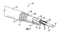
- FIG. 1 is a perspective view of an optical fiber cable according to an exemplary embodiment.
- FIG. 2 is a detailed side view showing wrapped core elements of the cable of FIG. 1 bound together via a film according to an exemplary embodiment.
- FIG. 3 is a cross-sectional view of a cable according to an exemplary embodiment.
- FIG. 4 is a detailed sectional view of a core element of the cable of FIG. 3 according to an exemplary embodiment.
- FIG. 5 is a detailed sectional view of a portion of a core element, film and jacket of the cable of FIG. 3 according to another exemplary embodiment.
- FIG. 6 is a cross-sectional view of a cable according to another exemplary embodiment.
- FIG. 7 is a cross-sectional view of a cable according to another exemplary embodiment.
- FIG. 8 is a schematic view showing a system and process for forming an optical cable having a thin film binder according to an exemplary embodiment.
- an optical communication cable e.g., a fiber optic cable, an optical fiber cable, etc.
- the cable embodiments disclosed herein include a thin film or membrane layer that surrounds and binds together the core elements of the cable (e.g., buffer tubes containing loose optical fibers, optical micro-modules, tight buffered optical fibers, filler rods, etc.).
- the film discussed herein is extruded over the core elements after the core elements are wound in a pattern or arrangement (e.g., a spiral pattern, a helical pattern, SZ pattern, etc.) around a central support member.
- the film is rapidly cooled and solidified around the core element such that the film contracts applying a radially inwardly directed force onto the core elements.
- the radial inwardly directed force increases the normal force between the core elements and the central strength element which acts to limit or prevent relative movement between the core elements and the central strength element as the elements are advanced through the cable assembly process.
- the radial force provided by the film acts to maintain the core elements in the wound pattern by preventing or limiting the core elements from unwinding from around the central strength member.
- this restraining force provided by the film maintains the core elements in the desired wound pattern as the additional components (e.g., armor material, cable jackets, etc.) are applied to form the completed cable.
- the film is an elastic sleeve that forms an interference fit with the core elements of the cable.
- the optical cables discussed herein include optical fiber micromodules that have low or zero extra fiber length (EFL, such as less than an average of about 0.1% or less per fiber per micromodule) within the buffer tube of the micromodules.
- EFL extra fiber length
- micromodules may include densely packed optical fibers within a buffer tube in which the inner surface of the buffer tube contacts the outer surface of one or more optical fibers within the buffer tube. The dense packing of optical fibers within the micromodules allows for smaller cross-sectional area optical units. However, the lack of EFL and the tight packing may also act to transfer external forces to the optical fibers which may result in optical signal attention.
- the film binder discussed herein distributes the binding forces evenly around both the circumference of the core elements and axially along the length of the core elements.
- the thin film binders discussed herein may act to limit or prevent such strain based attenuation.
- Cable 10 includes a cable body, shown as cable jacket 12 , having an inner surface 14 that defines a inner passage or cavity, shown as central bore 16 .
- inner surface 14 of jacket 12 defines an internal area or region within which the various cable components discussed below are located.
- a plurality of optical transmission elements, shown as optical fibers 18 are located within bore 16 .
- cable 10 provides structure and protection to optical fibers 18 during and after installation (e.g., protection during handling, protection from elements, protection from vermin, etc.).
- cable 10 includes a plurality of core elements located within central bore 16 .
- a first type of core element is an optical transmission core element, and these core elements include bundles of optical fibers 18 that are located within tubes, such as buffer tubes 20 .
- One or more additional core elements shown as filler rods 22 , may also be located within bore 16 .
- Filler rods 22 and buffer tubes 20 are arranged around a central support, shown as central strength member 24 formed from a material such as glass-reinforced plastic or metal (e.g., steel). Together, buffer tubes 20 containing optical fibers 18 , filler rods 22 and central strength member 24 form the core 26 of cable 10 .
- Cable 10 includes a film or membrane, shown as binding film 28 , located around buffer tubes 20 and filler rods 22 of cable 10 .
- thin film 28 is an extruded thin film that cools to provide an inwardly directed force on to buffer tubes 20 and filler rods 22 .
- the inwardly directed force provided by film 28 assists to hold buffer tubes 20 and filler rods 22 in a fixed position relative to central strength member 24 by increasing the normal force and therefore frictional force between these components.
- an interference fit is provided between the outer surfaces of the core elements and film 28 such that film 28 acts to provide an inwardly directed force onto the core elements of cable 10 .
- the inwardly directed force provided by film 28 acts to prevent/resist unraveling of the wound core elements.
- an adhesive e.g., hot melt adhesive
- the film of cable 10 is a constraining element or constraining sleeve that acts to bind together the core of cable 10 as discussed herein.
- the film of cable 10 is an elastic sleeve that applies a radial inwardly directed force as discussed herein.
- film 28 is formed from a first material, and jacket 12 is formed from a second material.
- the first material is different from the second material.
- the material type of the first material is different from the material type of the second material.
- film 28 may be formed from a variety of extruded polymer materials.
- film 28 may be formed from low-density polyethylene (LDPE), polyester, or polypropylene.
- LDPE low-density polyethylene
- film 28 is formed from a linear LDPE.
- film 28 is formed from an LDPE material having a modulus of elasticity between 600 MPa and 1000 MPa, and more specifically about 800 MPa (e.g., 800 MPa plus or minus 5 percent).
- film 28 is formed from a polyester material having a modulus of elasticity between 2000 MPa and 2800 MPa, and more specifically about 2400 MPa (e.g., 2400 MPa plus or minus 5 percent).
- the material of film 28 may include a coloring material.
- film 28 may be colored the same as jacket 12 .
- the material of film 28 may be a polymer material (e.g., LDPE, PP) including carbon black coloring material, and the different material of jacket 12 may be a different polymer material (e.g., medium density polyethylene) that also includes carbon black coloring material.
- film 28 may include UV stabilizing compounds and may include weakened areas (e.g., lower thickness areas) that facilitate tearing, for example via rip cord 42 .
- the first material of film 28 is different from the second material of jacket 12 .
- film 28 is formed from a first material that is extruded at an earlier time or earlier stage in cable production than jacket 12 .
- film 28 is formed prior to formation of jacket 12 .
- a first extrusion process forms film 28 at an earlier time in cable production
- a second extrusion process forms jacket 12 at a later time in cable production.
- the first material of film 28 and the second material of jacket 12 are the same type of material (e.g., both are MDPE, PP, etc.) that are associated with cable 10 at different time points during production of cable 10 .
- the first material of film 28 and the second material of jacket 12 are the different types of material (e.g., film 28 is a LDPE and jacket 12 is MDPE) and are also associated with cable 10 at different time points during production of cable 10 .
- cables discussed herein including two extruded layers may include various structures not present in a cable having a single extruded layer (e.g., a single extruded outer jacket layer).
- film 28 includes an outer surface 41 that interfaces with inner surface 14 of jacket 12 .
- cable 10 may include gaps, air pockets or delaminations between jacket 12 and film 28 .
- there may be a region of mixed material including a mixture of both the material of film 28 and the material of jacket 12 .
- the density of the material of film 28 increases in the radially inward direction
- the density of the material of jacket 12 increases in the radially outward direction.
- a layer of powder such as water absorbing powder or particles, such as super absorbent polymer (SAP) or a water swellable gel or liquid, is located within bore 16 .
- the inner surface of film 28 includes the water absorbent particles or other material that that directly contacts the outer surfaces of buffer tubes 20 and filler rods 22 under the radial inwardly directed force applied by film 28 .
- contact between film 28 and buffer tubes 20 and filler rods 22 may include contact through certain discontinuous intermediate or filler materials that may be present within bore 16 , such as SAP particles, SAP yarns and/or water swellable gels and liquids, that may be positioned within bore 16 .
- contact between film 28 and buffer tubes 20 and filler rods 22 does not include contact through a circumferentially continuous layer of material located between film 28 and buffer tubes 20 .
- the inner surface of film 28 directly contacts the outer surface of buffer tubes 20 such at least a portion of the inner surface of film 28 directly physically interacts with the outer surface of the buffer tube 20 without intervening material.
- the water blocking gel has a low gel viscosity, for example lower than 4000 mPas.
- the SAP material may have an average polymer particle size between 5 micrometers and 20 micrometers.
- cable 10 includes a reinforcement sheet or layer, shown as armor layer 30 , that is located outside of film 28 .
- Armor layer 30 is wrapped around the interior elements (including optical fibers 18 ) of cable 10 such that armor layer 30 surrounds optical fibers 18 .
- Armor layer 30 generally provides an additional layer of protection to fibers 18 within cable 10 , and may provide resistance against damage (e.g., damage caused by contact or compression during installation, damage from the elements, damage from rodents, etc.).
- optical core 26 is shown with film 28 in cross-section to show the wrap or winding pattern of buffer tubes 20 and filler rods 22 around central strength member 24 .
- film 28 includes an inner surface 32 that extends in the axial direction shown in FIG. 2 (i.e., left and right in the orientation of FIG. 2 ) and is in contact with the radially exterior portions of the outer surfaces of buffer tubes 20 and filler rods 22 in the axial direction.
- optical core 26 is shown having at least one spiral wrapped section.
- optical core 26 is shown in an SZ wrapped pattern (also referred to as an SZ stranding pattern).
- optical core 26 includes a right-handed spirally wrapped section 34 , a reversal section 36 and a left-handed spirally section 38 .
- the core elements such as buffer tubes 20 and filler rods 22
- the core elements are wrapped spirally in the right-handed direction.
- the core elements, such as buffer tubes 20 and filler rods 22 are wrapped spirally in the left-handed direction.
- Reversal section 36 is a section that provides the transition between the right-handed spirally wrapped section 34 and the left-handed spirally wrapped section 38 .
- reversal section 36 is shaped as a sinusoidal function.
- optical core 26 may include a large number of repeating sections similar to the sections shown in FIG. 2 .
- the right-handed spirally wrapped sections and left-handed spirally wrapped sections alternate along the length of optical core 26 with reversal sections located between each oppositely wrapped spiral section.
- spirally wrapped sections include a pitch length (also known as lay length) which is the axial distance required for one of the core elements to complete a full revolution around strength member 24 .
- core 26 may have an average pitch length (or average lay length) which is the average of the multiple individual pitch lengths along the length of core 26 .
- each of sections 34 , 36 and 38 have axial lengths shown as L1, L2 and L3, respectively.
- L1 is the length of right-handed spirally wrapped section 34 and is the distance between the reversal sections at the beginning and end of right-handed spirally wrapped section 34 .
- L3 is the length of left-handed spirally wrapped section 38 and is the distance between the reversal sections at the beginning and end of left-handed spirally wrapped section 38 .
- L2 is the length of reversal section 36 and generally is the distance between the beginning point and the end point of section 36 .
- the beginning point of section 36 is the point at which the pitch of right-handed spirally wrapped section 34 starts to change following section 34 moving in a direction from left to right in the orientation of FIG. 2
- the end point of section 36 is the point at which the pitch of left-handed spirally wrapped section 38 starts to change following section 38 moving in a direction from right to left in the orientation of FIG. 2 .
- L1 and L3 are expressed in terms of the number pitch lengths that reside in the section. In other words, L1 and L3 may be expressed in terms of the number of revolutions of the core elements that are contained within each section. In various embodiments, L1 and L3 are less than 10 revolutions and more than one half revolution (i.e., less than 10 pitch lengths or lay lengths and more than one half pitch length or lay lengths). In various embodiments, L1 and L3 are between 1 revolution and 1.5 revolutions. In other embodiments, L1 and L3 are 7 revolutions, and in another embodiment, L1 and L3 are between 1 and 2 revolutions.
- L1 and L3 are substantially the same for each right-handed spirally wrapped section 34 and each left-handed spirally wrapped section 38 , respectively, along the length core 26 .
- the frequency or position of reversal 36 varies along the axis of core 26 , such that L1 and L3 are different at different axial positions along core 26 .
- core 26 may have an average pitch length for the right-handed spirally wrapped section 34 and for the left-handed spirally wrapped section 38 , which is the average of all pitch lengths along the length of core 26 with in each section.
- L2 of reversal section 36 is between 45 mm and 100 mm.
- film 28 is positioned relative to the wrapped pattern of core 26 to restrain the core 26 from unwinding or unwrapping during cable construction. For example, in one embodiment (as shown in FIG. 8 ), film 28 is applied to the outer surface of core 26 immediately after the core elements are wrapped around central strength member 24 in the desired pattern. In this arrangement, film 28 holds the wrapped core 26 in the desired wrapped pattern as additional cable components (e.g., armor 30 , and/or jacket 12 ) are applied over core 26 .
- core 26 is an optical communication bundle in which the outer surface of film 28 defines the outermost surface of the communication bundle. In such embodiments, core 26 does not include outer layers such as jacket 12 .
- film 28 is configured to provide substantially continuous contact with a portion of the outer surface of each of the core elements of core 26 for at least one pitch length within right-handed spirally wrapped section 34 and/or left-handed spirally wrapped section 38 . In other embodiments, film 28 is configured to provide substantially continuous contact with a portion of the outer surface of each of the core elements of core 26 for at least five pitch lengths within right-handed spirally wrapped section 34 and/or left-handed spirally wrapped section 38 .
- film 28 is configured to provide substantially continuous contact with a portion of the outer surface of each of the core elements of core 26 extending over at least one right-handed spirally wrapped section 34 , at least one left-handed spirally wrapped section 38 and over the intervening reversal sections 36 .
- film 28 is configured to provide substantially continuous contact with a portion of the outer surface of each of the elements of core 26 extending over at least ten right-handed spirally wrapped section 34 , at least ten left-handed spirally wrapped section 38 and over the intervening reversal sections 36 .
- film 28 is configured to impart a radial inwardly directed force over reversal sections 36 causing inner surfaces of each of the core elements within the reversal section to engage the central strength member 24 .
- This force may act to limit axial sliding of the core elements relative to strength member 24 during manufacture.
- contact between film 28 and the outer surfaces of core 26 includes direct contact between the inner surface 32 of film 28 and the outer surfaces of core 26 , indirect contact in which particulate, gel or liquid material (such as water blocking/absorbent materials) are interspersed between core 26 and film 28 , or generally any arrangement that allows the radially inwardly directed force generated by the contractive forces of film 28 to be applied to core 26 .
- a cable 40 is shown according to an exemplary embodiment. Cable 40 is similar to cable 10 except as discussed herein. Cable 40 is shown without armor layer 30 , according to an exemplary embodiment.
- inner surface 14 of jacket 12 faces outer surface 41 of film 28 .
- inner surface 14 of jacket 12 faces and directly contacts outer surface 41 of film 28 .
- one component that directly contacts another component directly physically interacts with the component without intervening layers of material or gaps of air/space.
- one component or surface that faces another component or surface is aligned with or pointed toward the component or surface and may or may not include intervening layers of material or gaps of air/space.
- jacket 12 is made from an extruded polymer material that is different from the extruded polymer material that forms film 28 .
- jacket 12 is made from an extruded medium density polyethylene material
- film 28 is formed from an extruded low density polyethylene material.
- opening or removal of jacket 12 e.g., via a rip cord
- inner surface 14 of jacket 12 faces but does not directly contact outer surface 41 of film 28 , and in such embodiments, a layer, such as armor 30 is located between jacket 12 and film 28 .
- film 28 contracts such that film 28 is in tension around buffer tubes 20 of core elements 48 .
- film 28 forms an undulating pattern of interspersed convex portions 49 and concave portions 51 resulting from the tension generated as film 28 cools and/or vacuum applied to the interior of film 28 during extrusion and cooling.
- concave portions 51 of film 28 engages a portion of the outer circumference of each buffer tube 20 .
- the portion of the outer surface of buffer tube 20 engaged by concave portions 51 can be defined by angle A.
- angle A is between 10 degrees and 90 degrees, specifically is between 20 degrees and 80 degrees and more specifically is between 30 degrees and 70 degrees.
- angle A is greater than 10 degrees and less than 360 degrees.
- film 28 includes concave portions 51 that engage the outer surfaces of each buffer tube 20 at each axial cross-sectional position. This structure is in contrast to a helically wound binder that engages a buffer tube tangentially and that engages discreet portions of less than all of the buffer tubes at each axial position along at least a portion of the length of cable 40 .
- film 28 cools such that film 28 is in tension and applies a radially inwardly directed force onto buffer tubes 20 .
- film 28 is an elastic sleeve that surrounds core elements 48 .
- film 28 is a non-helical binder, and in such embodiments, the cables discussed herein do not include a helically wound binder located between core elements 48 and jacket 12 .
- the residual strain within film 28 following cooling is proportional to the radial force applied to buffer tubes 20 .
- film 28 because film 28 is extruded over buffer tubes 20 and cools to apply the binding force, film 28 includes low or no torsional stress and/or low or no stress in the circumferential direction.
- film 28 may provide radial forces coupling core elements 48 to central strength member 24 without significant torsional or circumferential stress.
- film 28 may be a non-extruded elastic sleeve imparting binding force to core elements 48 as discussed herein.
- film 28 is continuous both circumferentially and axially along at least a portion of the axial length of core 26 , at each axial cross-sectional position within film 28 , the radially inwardly directed force applied by film 28 is evenly distributed circumferentially around core 26 .
- the coupling normal force experienced by central strength member 24 transmitted from film 28 through buffer tubes 20 is substantially evenly distributed around central strength member 24 .
- the coupling normal force experienced by the central strength member within in a cable using a helical binder is distributed substantially following the helical path of the binder, and thus is not evenly distributed circumferentially around the central strength member at a given axial position.
- the embodiment of cable 40 shown in FIG. 3 includes six optical fiber transmission elements, shown as core elements 48 , each including a buffer tube 20 and optical fibers 18 . As shown the six core elements 48 are evenly spaced around central strength member 24 . As discussed above, FIG. 2 shows film 28 in substantially continuous engagement with outer surfaces of the elements of core 26 in the axial direction. In addition to the axial contact, as shown in FIG. 3 , film 28 is also in contact with the radial outermost surfaces of each of the core elements 48 in the circumferential direction around core elements 48 . It is through both the axial contact and the circumferential contact that film 28 acts to apply a radially inward direct force that is substantially continuous in the axial and circumferential directions to maintain core 26 in the stranding pattern as discussed above.
- the outer width between opposing sections of outer surfaces of film 28 e.g., the cross-sectional dimension of film 28 passing through the center of bore 16
- the inner width between opposing sections of the inner surface of film 28 e.g., the cross-sectional dimension of film 28 passing through the center of bore 16
- film 28 has an average outer width of between 1 mm and 10 mm.
- cable 40 and/or cable 10 may include various additional cable components.
- cable 10 may include one or more rip cord 42 located between core 26 and film 28 . Rip cord 42 facilitates opening of cable jacket 12 and access to the optical fibers of cable 10 , and because rip cord 42 is between core 26 and film 28 it also facilitates opening of film 28 .
- the material of film 28 may be configured to not significantly bond with the material of buffer tubes 20 allowing rip cord 42 to facilitate separation of both cable jacket 12 and film 28 from buffer tubes 20 .
- film 28 is formed from a polyethylene material
- buffer tubes 20 are formed from a material such as polypropylene or polycarbonate that does not substantially bond to the polyethylene of film 28
- cable 40 may also include one or more additional elongate elements shown as elements 44 and 46 .
- elements 44 are located within bore 16 and element 46 is shown embedded in jacket 12 .
- elements 44 and 46 are elongate strength elements, and in another embodiment, elements 44 and 46 are water blocking yarns.
- jacket 12 includes one or more co-extruded discontinuities (e.g., extruded regions of polypropylene) that extend axial through the jacket, and in such embodiments, the discontinuity facilitates opening of jacket 12 by tearing.
- film 28 may be bonded to jacket 12 acting to buttress the jacket limiting the chance of accidental opening or splitting along the discontinuity. In such embodiments, film 28 may act to limit crack propagation through the material of jacket 12 .
- each core element includes optical fibers 18 located within a bore 50 defined by inner surface 52 of buffer tube 20 .
- Buffer tube 20 also includes an outer surface 54 that is in contact with film 28 as discussed above.
- each core element includes twelve optical fibers 18 , and in this arrangement three of the twelve optical fibers are located in a central area of bore 50 , and nine of the twelve are located around the inner three fibers and at least some of the outer nine fibers have outer surfaces 56 that engage inner surface 52 of buffer tube 20 .
- core element 48 includes at least nine optical fibers 18 located within buffer tube 20 .
- core element 48 of cable 40 includes 2, 4, 6, 8, 12, 24, 36 or more optical fibers 18 .
- the inner diameter of buffer tube 20 is selected to provide densely packed optical fibers 18 within buffer tube 20 .
- ID1 is between 0.5 mm and 3.0 mm. In other embodiments, ID1 is between 0.8 mm and 2.0 mm.
- a binding membrane such as film 28
- a typical helical tape or yarn binder will tend to evenly distribute the binding forces both axially and circumferentially which may limit strain-based attenuation experienced by a signal with the optical fibers.
- fibers 18 extend between first and second opposing ends of the respective buffer tube, and in some such embodiments, the length of each fiber 18 is substantially the same length as buffer tube 20 .
- the optical transmission element has zero or near zero excess fiber length (EFL) within the tube.
- the core element 48 may be referred to as a mircomodule that has a cross-sectional diameter less than the diameter of a buffer tube of loose tube cable.
- core element 48 may be a buffer tube of loose tube cable, and in such embodiments, may have an EFL greater than zero.
- film 28 has a radial dimension or thickness shown as T1
- jacket 12 has a radial dimension or thickness shown as T2.
- T1 is less than 100 micrometers
- T2 is greater than 1 millimeter.
- T1 is between 25 micrometers and 75 micrometers and more specifically is about 50 micrometers.
- T2 is between 1 millimeter and 5 millimeters, specifically is between 1 millimeter and 3 millimeters and more specifically is between 1.2 millimeters and 1.4 millimeters.
- jacket 12 is less than 5 millimeters.
- jacket 12 is a thin jacket, and T2 is less than or equal to 0.2 mm.
- T1 is between 0.5% and 10% of T2, specifically T1 is between 1.5% and 6.5% of T2, and more specifically T1 is between 3.5% and 4.5% of T2.
- the outer diameter of jacket 12 of cable 10 is between 4 millimeters and 10 millimeters, specifically is between 5 millimeters and 6 millimeters, and more specifically is about 5.4 millimeters (e.g., 5.4 millimeters plus or minus 0.1 millimeter).
- Buffer tube 20 has a radial dimension or thickness shown as T3.
- T3 may vary based upon the number of fibers 18 located within tube 20 .
- T3 is between 0.2 millimeters and 0.7 millimeters, specifically is between 0.3 millimeters and 0.6 millimeters and more specifically is between 0.4 millimeters and 0.5 millimeters.
- T3 is about 0.32 millimeters (e.g., 0.32 mm plus or minus 0.01 millimeters), and in another embodiment, T3 is about 0.36 millimeters (e.g., 0.36 mm plus or minus 0.01 millimeters).
- buffer tubes 20 are formed from one or more polymer material including polypropylene (PP), polybutylene terephthalate (PBT), polycarbonate (PC), polyamide (PA), polyoxymethylene (POM), poly(ethene-co-tetrafluoroethene) (ETFE), etc.
- PP polypropylene
- PBT polybutylene terephthalate
- PC polycarbonate
- PA polyamide
- POM polyoxymethylene
- ETFE poly(ethene-co-tetrafluoroethene)
- core elements 48 can include a wide variety of optical fibers including multi-mode fibers, single mode fibers, bend insensitive fibers, etc.
- core elements 48 are micromodules of densely packed fibers within a tube.
- core elements 48 are buffer tubes of a loose tube cable.
- core elements 48 are tight buffered optical fibers.
- cable 60 is substantially similar to cable 10 discussed above, except cable 60 includes eight core elements 48 .
- the outer diameter of jacket 12 of cable 60 is between 6 millimeters and 7 millimeters, and more specifically is about 6.4 millimeters (e.g., 6.4 millimeters plus or minus 0.1 millimeter).
- cable 70 is substantially similar to cable 10 discussed above, except cable 70 includes twelve core elements 48 .
- the outer diameter of jacket 12 of cable 70 is between 8 millimeters and 9 millimeters, and more specifically is about 8.2 millimeters (e.g., 8.2 millimeters plus or minus 0.1 millimeter).
- central strength member 24 of cable 70 includes an outer coating layer 72 .
- cables discussed herein may include 2, 4, 10, 14, 16, 20, 24, 32, etc. core elements 48 .
- FIG. 8 a schematic view of a process and system 100 for forming an SZ stranded core element surrounded by a binding film or membrane, such as film 28 , is shown according to an exemplary embodiment.
- An oscillating nose piece 102 wraps core elements 48 around a central strength member in a spiral pattern, such as SZ stranding pattern 104 .
- Nose piece 102 is located within an extruded film cone 106 that is formed as the material to form film 28 exits from the extruder. The extruded film material 106 is drawn down to closely adhere to core 26 .
- a constraining device shown as caterpuller 110 , engages the film coated core 26 .
- caterpuller 110 engages core 26 to provide physical support to the wound core elements 48 while the material of extruded film 28 cools and solidifies.
- caterpuller 110 holds core elements 48 in place in the desired stranding pattern while film 28 cools and solidifies, and once film 28 is solidified, the tension within film 28 generates radial inwardly directed forces that hold core elements 48 in place in the desired stranding pattern.
- Caterpullers 110 also impart movement to film coated core 26 in the direction of arrow 114 to move film coated core 26 to receive other cable components including cable jacket 12 at subsequent stations in the cable assembly process.
- system 100 may include other constraining devices, for example capstans may be used in place of caterpuller 110 .
- system 100 is configured to accelerate the cooling of film 28 by providing an active cooling element that removes heat from the extruded material that forms film 28 .
- system 100 is configured to direct a cooling fluid, shown as cooling fluid 116 (e.g., air, water, other coolant, etc.), on to the extruded material that forms film 28 .
- Fluid 116 helps remove heat from film 28 accelerating the solidification process.
- system 100 is configured to apply SAP particles or powder 118 into the region between film 28 and core 26 .
- SAP 118 is applied to the interior of extruded film cone 106 , and may be driven by a vacuum applied to the interior of extruded film cone 106 .
- SAP 118 is driven into the interstices between elements 48 within bore 16 .
- SAP particles are embedded into the molten material of extruded film cone 106 .
- film 28 upon solidification, film 28 is formed with embedded water blocking particles along its interior surface.
- embedded water blocking particles are also applied to the outer surface of film 28 .
- film 28 also acts as the water blocking agent eliminating the need to add separate water blocking layers, for some cable applications.
- film 28 contracts applying a radial inwardly directed force that is evenly distributed around core 26 .
- film 28 acts to hold core 26 in the desired wrapped pattern while other components of the cable are added.
- film 28 because film 28 is extruded around core 26 (as opposed to being helically wrapped) and is cooled such that the tension within film 28 acts to apply the inward binding force, film 28 does not apply significant torsional forces to core 26 .
- system 100 may be configured to apply an adhesive to core 26 .
- a hot melt adhesive is applied to core 26 adjacent to nose piece 102 .
- system 100 may be configured to perform a method of forming an optical cable.
- the method includes wrapping a plurality of elongate optical transmission elements around an elongate central support member.
- the method also includes extruding a film formed around the plurality of wrapped elongate optical transmission elements such that an inner surface of the film is in contact with an outer surface of each of the plurality of elongate optical transmission elements.
- the method includes cooling the film such that the film solidifies applying a radially inwardly directed force to the plurality of elongate optical transmission elements.
- the method also includes extruding a cable body around the film following cooling of the film.
- the film and jacket may be formed from the same type of material or different types of material.
- the inner surface of the film first contacts the outer surface of each of the plurality of elongate optical transmission elements within a distance of 100 mm from the point at which the elongate optical transmission elements are wrapped around an elongate central support member.
- the first material is a low density polyethylene material and the second material a medium density polyethylene material.
- the method includes engaging an outer surface of the film after extruding the film and prior to solidification of the film. In one such embodiment, the engaging is performed by an advancing device, such as caterpuller 110 .
- cable jacket 12 may be a variety of materials used in cable manufacturing such as medium density polyethylene, polyvinyl chloride (PVC), polyvinylidene difluoride (PVDF), nylon, polyester or polycarbonate and their copolymers.
- the material of cable jacket 12 may include small quantities of other materials or fillers that provide different properties to the material of cable jacket 12 .
- the material of cable jacket 12 may include materials that provide for coloring, UV/light blocking (e.g., carbon black), burn resistance, etc.
- the cable embodiments discussed herein may include one or more electrical conductive element located within bore 16 .
- the conductive element may be a copper conductive element having a diameter of 12 AWG, 14 AWG, 16 AWG, 18 AWG, 20 AWG, 22 AWG, 24 AWG, or smaller.
- the radially directed inwardly directed force applied by film 28 helps restrain and hold the wound core elements 48 in place during subsequent manufacturing process and also limits axially sliding that may occur between core elements and the strength element.
- the magnitude of the static friction force is related to the thickness of the film 28 .
- the static friction force for a 100 mm section of core elements 48 (without a jacket) is at least 10 N, such as about 12.4 N
- the average static friction force for a 200 mm section of core elements 48 is at least 20 N, such as about 23.1 N.
- the net spring force of the core elements 48 within the reverse-oscillatory stranding pattern is about 10 N or less for a 100 mm section to prevent or limit axial migration of the core elements 48 .
- the average static friction force for a 100 mm section of stranded elements is at least 20 N, such as at least 30 N, and/or the average static friction force for a 200 mm section of stranded elements is at least 40 N, such as at least 50 N.
- cable jacket 12 and/or buffer tubes 20 may have an oval, elliptical, square, rectangular, triangular or other cross-sectional shape.
- the passage or lumen of the cable or buffer tube may be the same shape or different shape than the shape of cable jacket 12 or buffer tube.
- cable jacket 12 and/or buffer tube may define more than one channel or passage.
- the multiple channels may be of the same size and shape as each other or may each have different sizes or shapes.
- optical fibers may be flexible, transparent optical fibers made of glass or plastic.
- the fibers may function as a waveguide to transmit light between the two ends of the optical fiber.
- Optical fibers may include a transparent core surrounded by a transparent cladding material with a lower index of refraction. Light may be kept in the core by total internal reflection.
- Glass optical fibers may comprise silica, but some other materials such as fluorozirconate, fluoroaluminate, and chalcogenide glasses, as well as crystalline materials, such as sapphire, may be used.
- the light may be guided down the core of the optical fibers by an optical cladding with a lower refractive index that traps light in the core through total internal reflection.
- the cladding may be coated by a buffer and/or another coating(s) that protects it from moisture and/or physical damage.
- These coatings may be UV-cured urethane acrylate composite materials applied to the outside of the optical fiber during the drawing process. The coatings may protect the strands of glass fiber.
- the binding element e.g., sleeve, film, membrane
- the jacket of the respective cable may include, such as primarily include or is formed from, polyethylene.
- the polyethylene may be high-density polyethylene having a density about 0.93 to 0.97 g/cm 3 .
- the buffer tubes include polycarbonate, as discussed above, and may further include an exterior and/or interior layer of another polymer, such as polybutylene terephthalate or polypropylene, which may serve to limit or mitigate crack initiation or propagation through the polycarbonate.
- One embodiment includes a cable having six tubes positioned around a glass-reinforced plastic strength member.
- the strength member may have a diameter of about 1.5 mm.
- the tubes may be polypropylene or a composite of a polycarbonate inner layer with polybutylene terephthalate outer layer.
- the tubes may have an outer diameter of 1.4 mm, 1.3 mm, or 1.1 mm.
- the tubes may each include twelve optical fibers.
- the cable includes two water-blocking yarns wrapped around the strength member, such about 1100 dtex in fineness of the yarn.
- the cable includes a stranding lay length or pitch length, as discussed above, in the range of between about 56 to 60 mm.
- the core includes a binding element, as disclosed herein, and possibly includes one or more ripcords to remove the binding element and/or the jacket.
- the core has an outer diameter of about 4.4 mm.
- the jacket is formed from high-density polyethylene, has a thickness of about 0.5 mm, and may be colored black. The resulting outer diameter of the cable is about 5.3 mm
- Another embodiment includes a cable having eight tubes positioned around a glass-reinforced plastic strength member.
- the strength member may have a diameter of about 2.5 mm.
- the tubes may be polypropylene or a composite of a polycarbonate inner layer with polybutylene terephthalate outer layer.
- the tubes may have an outer diameter of 1.4 mm, 1.3 mm, or 1.1 mm.
- the tubes may each include twelve optical fibers.
- the cable includes two water-blocking yarns wrapped around the strength member, such about 1100 dtex in fineness of the yarn.
- the cable includes a stranding lay length or pitch length, as discussed above, in the range of between about 66 to 70 mm.
- the core includes a binding element, as disclosed herein, and possibly includes one or more ripcords to remove the binding element and/or the jacket.
- the core has an outer diameter of about 5.4 mm.
- the jacket is formed from high-density polyethylene, has a thickness of about 0.5 mm, and may be colored black. The resulting outer diameter of the cable is about 6.3 mm
- Another embodiment includes a cable having twelve tubes positioned around a glass-reinforced plastic strength member.
- the strength member may have a diameter of about 2.5 mm or 4.3 mm.
- the tubes may be polypropylene or a composite of a polycarbonate inner layer with polybutylene terephthalate outer layer.
- the tubes may have an outer diameter of 1.4 mm, 1.3 mm, or 1.1 mm.
- the tubes may each include twelve optical fibers.
- the cable includes two water-blocking yarns wrapped around the strength member, such about 1100 dtex in fineness of the yarn.
- the cable includes a stranding lay length or pitch length, as discussed above, in the range of between about 80 to 84 mm.
- the core includes a binding element, as disclosed herein, and possibly includes one or more ripcords to remove the binding element and/or the jacket.
- the core has an outer diameter of about 7.2 mm.
- the jacket is formed from high-density polyethylene, has a thickness of about 0.5 mm, and may be colored black. The resulting outer diameter of the cable is about 8.1 mm.
- cables similar to the above described examples and other embodiments disclosed herein may include at least four tubes carrying optical fibers and/or no more than twenty tubes, such as at least six and/or no more than eighteen tubes.
- the central strength member of any one of the above examples may include steel or even stranded stainless steel, such as a steel rod up jacketed with polyethylene insulator.
- the central strength member is at least about 1.25 mm in diameter and/or no more than about 5 mm in diameter.
- tubes having an outer diameter of about 1 mm or less where the tubes may still include twelve optical fibers, but the optical fibers may have smaller diameters than typical optical fibers, such as diameters as small as 210 micrometers or less, such as about 200 micrometers in diameter.
- 1 mm tubes or other size tubes as disclosed herein may include fewer optical fibers than twelve, such as 8 or less optical fibers, or 4 or less optical fibers.
- larger tubes may be used, such as tubes that are greater than 1.4 mm in diameter and less than about 2 mm in diameter, where such tubes may carry more than twelve optical fibers and/or no more than a hundred optical fibers, such as twenty-four optical fibers of about 200 micrometers in diameter within a 1.7 mm tube.
- the cables may not include water-blocking yarn, or may use other sizes or numbers of water-blocking yarn.
- the lay or pitch length of the stranding is at least about 50 mm and/or no more than about 100 mm.
- the core has an outer diameter that is at least about 3 mm and/or no more than about 10 mm, such as at least about 4 mm and/or no more than about 9 mm.
- the wall thickness of the jacket is at least 0.3 mm and/or no more than 0.8 mm.
- the material of the jacket may be any type of polyethylene, or may be a flame-retardant material, such as filled polyvinyl chloride or a low-smoke-zero-halogen material.
- the jacket may be orange, green, or otherwise colored.
- the resulting outer diameter of contemplated cables disclosed herein is at least 4 mm and/or no greater than about 12 mm, such as at least about 5 mm and/or no greater than about 10 mm.
- the above disclosure may allow for a particular narrow minicable, able to be routed in small ducts and consuming little space.
Abstract
Description
Claims (30)
Priority Applications (18)
| Application Number | Priority Date | Filing Date | Title |
|---|---|---|---|
| US14/231,875 US8913862B1 (en) | 2013-09-27 | 2014-04-01 | Optical communication cable |
| BR112016005880A BR112016005880A2 (en) | 2013-09-27 | 2014-09-19 | optical communication cable |
| CN201480057059.2A CN105637397B (en) | 2013-09-27 | 2014-09-19 | Optical communication cable |
| CA3209256A CA3209256A1 (en) | 2013-09-27 | 2014-09-19 | Optical communication cable |
| JP2016518144A JP6507153B2 (en) | 2013-09-27 | 2014-09-19 | Optical communication cable |
| PL14776977T PL3049845T3 (en) | 2013-09-27 | 2014-09-19 | Optical communication cable |
| MX2016003550A MX2016003550A (en) | 2013-09-27 | 2014-09-19 | Optical communication cable. |
| EP14776977.2A EP3049845B1 (en) | 2013-09-27 | 2014-09-19 | Optical communication cable |
| CA2925160A CA2925160C (en) | 2013-09-27 | 2014-09-19 | Optical communication cable |
| EP17191135.7A EP3273282B1 (en) | 2013-09-27 | 2014-09-19 | Method of forming an optical cable |
| PCT/US2014/056478 WO2015047896A2 (en) | 2013-09-27 | 2014-09-19 | Optical communication cable |
| AU2014327162A AU2014327162B2 (en) | 2013-09-27 | 2014-09-19 | Optical communication cable |
| US15/073,770 US10539756B2 (en) | 2013-09-27 | 2016-03-18 | Optical communication cable |
| AU2019232892A AU2019232892A1 (en) | 2013-09-27 | 2019-09-20 | Optical communication cable |
| US16/720,361 US10914907B2 (en) | 2013-09-27 | 2019-12-19 | Optical communication cable |
| US17/145,781 US11409064B2 (en) | 2013-09-27 | 2021-01-11 | Optical communication cable |
| AU2021203639A AU2021203639A1 (en) | 2013-09-27 | 2021-06-03 | Optical communication cable |
| US17/878,166 US11880078B2 (en) | 2013-09-27 | 2022-08-01 | Optical communication cable |
Applications Claiming Priority (2)
| Application Number | Priority Date | Filing Date | Title |
|---|---|---|---|
| US201361883286P | 2013-09-27 | 2013-09-27 | |
| US14/231,875 US8913862B1 (en) | 2013-09-27 | 2014-04-01 | Optical communication cable |
Related Child Applications (1)
| Application Number | Title | Priority Date | Filing Date |
|---|---|---|---|
| PCT/US2014/056478 Continuation WO2015047896A2 (en) | 2013-09-27 | 2014-09-19 | Optical communication cable |
Publications (1)
| Publication Number | Publication Date |
|---|---|
| US8913862B1 true US8913862B1 (en) | 2014-12-16 |
Family
ID=52015313
Family Applications (5)
| Application Number | Title | Priority Date | Filing Date |
|---|---|---|---|
| US14/231,875 Active US8913862B1 (en) | 2013-09-27 | 2014-04-01 | Optical communication cable |
| US15/073,770 Active 2034-05-02 US10539756B2 (en) | 2013-09-27 | 2016-03-18 | Optical communication cable |
| US16/720,361 Active US10914907B2 (en) | 2013-09-27 | 2019-12-19 | Optical communication cable |
| US17/145,781 Active US11409064B2 (en) | 2013-09-27 | 2021-01-11 | Optical communication cable |
| US17/878,166 Active US11880078B2 (en) | 2013-09-27 | 2022-08-01 | Optical communication cable |
Family Applications After (4)
| Application Number | Title | Priority Date | Filing Date |
|---|---|---|---|
| US15/073,770 Active 2034-05-02 US10539756B2 (en) | 2013-09-27 | 2016-03-18 | Optical communication cable |
| US16/720,361 Active US10914907B2 (en) | 2013-09-27 | 2019-12-19 | Optical communication cable |
| US17/145,781 Active US11409064B2 (en) | 2013-09-27 | 2021-01-11 | Optical communication cable |
| US17/878,166 Active US11880078B2 (en) | 2013-09-27 | 2022-08-01 | Optical communication cable |
Country Status (10)
| Country | Link |
|---|---|
| US (5) | US8913862B1 (en) |
| EP (2) | EP3273282B1 (en) |
| JP (1) | JP6507153B2 (en) |
| CN (1) | CN105637397B (en) |
| AU (3) | AU2014327162B2 (en) |
| BR (1) | BR112016005880A2 (en) |
| CA (2) | CA2925160C (en) |
| MX (1) | MX2016003550A (en) |
| PL (1) | PL3049845T3 (en) |
| WO (1) | WO2015047896A2 (en) |
Cited By (191)
| Publication number | Priority date | Publication date | Assignee | Title |
|---|---|---|---|---|
| US20140226940A1 (en) * | 2013-02-12 | 2014-08-14 | Nexans | Fiber optic cable with improved flexibility, low temperature and compression resistance |
| US20150168660A1 (en) * | 2013-12-16 | 2015-06-18 | Corning Cable Systems Llc | Rugged micromodule cable |
| US9119127B1 (en) | 2012-12-05 | 2015-08-25 | At&T Intellectual Property I, Lp | Backhaul link for distributed antenna system |
| US9154966B2 (en) | 2013-11-06 | 2015-10-06 | At&T Intellectual Property I, Lp | Surface-wave communications and methods thereof |
| US9209902B2 (en) | 2013-12-10 | 2015-12-08 | At&T Intellectual Property I, L.P. | Quasi-optical coupler |
| WO2015191391A1 (en) * | 2014-06-10 | 2015-12-17 | Corning Optical Communications LLC | Fiber optic cable structured to facilitate accessing an end thereof |
| US9312919B1 (en) | 2014-10-21 | 2016-04-12 | At&T Intellectual Property I, Lp | Transmission device with impairment compensation and methods for use therewith |
| WO2016115358A1 (en) * | 2015-01-15 | 2016-07-21 | Corning Optical Communications LLC | Hybrid optical fiber ribbon and power cable |
| US9461706B1 (en) | 2015-07-31 | 2016-10-04 | At&T Intellectual Property I, Lp | Method and apparatus for exchanging communication signals |
| US20160299306A1 (en) * | 2013-12-30 | 2016-10-13 | Corning Optical Communications LLC | Binder film system |
| US9490869B1 (en) | 2015-05-14 | 2016-11-08 | At&T Intellectual Property I, L.P. | Transmission medium having multiple cores and methods for use therewith |
| US9503189B2 (en) | 2014-10-10 | 2016-11-22 | At&T Intellectual Property I, L.P. | Method and apparatus for arranging communication sessions in a communication system |
| US9509415B1 (en) | 2015-06-25 | 2016-11-29 | At&T Intellectual Property I, L.P. | Methods and apparatus for inducing a fundamental wave mode on a transmission medium |
| US9520945B2 (en) | 2014-10-21 | 2016-12-13 | At&T Intellectual Property I, L.P. | Apparatus for providing communication services and methods thereof |
| US9525524B2 (en) | 2013-05-31 | 2016-12-20 | At&T Intellectual Property I, L.P. | Remote distributed antenna system |
| US9525210B2 (en) | 2014-10-21 | 2016-12-20 | At&T Intellectual Property I, L.P. | Guided-wave transmission device with non-fundamental mode propagation and methods for use therewith |
| US9531427B2 (en) | 2014-11-20 | 2016-12-27 | At&T Intellectual Property I, L.P. | Transmission device with mode division multiplexing and methods for use therewith |
| US20170017004A1 (en) * | 2014-03-13 | 2017-01-19 | Afl Telecommunications Llc | Cable for land based seismic array system |
| US9564947B2 (en) | 2014-10-21 | 2017-02-07 | At&T Intellectual Property I, L.P. | Guided-wave transmission device with diversity and methods for use therewith |
| US9577307B2 (en) | 2014-10-21 | 2017-02-21 | At&T Intellectual Property I, L.P. | Guided-wave transmission device and methods for use therewith |
| WO2017044783A1 (en) * | 2015-09-11 | 2017-03-16 | Afl Telecommunications Llc | Tactical deployable cables |
| US9608692B2 (en) | 2015-06-11 | 2017-03-28 | At&T Intellectual Property I, L.P. | Repeater and methods for use therewith |
| US9608740B2 (en) | 2015-07-15 | 2017-03-28 | At&T Intellectual Property I, L.P. | Method and apparatus for launching a wave mode that mitigates interference |
| US9615269B2 (en) | 2014-10-02 | 2017-04-04 | At&T Intellectual Property I, L.P. | Method and apparatus that provides fault tolerance in a communication network |
| JP2017072801A (en) * | 2015-10-09 | 2017-04-13 | 株式会社フジクラ | Optical fiber cable |
| US9628116B2 (en) | 2015-07-14 | 2017-04-18 | At&T Intellectual Property I, L.P. | Apparatus and methods for transmitting wireless signals |
| US9628854B2 (en) | 2014-09-29 | 2017-04-18 | At&T Intellectual Property I, L.P. | Method and apparatus for distributing content in a communication network |
| US9640850B2 (en) | 2015-06-25 | 2017-05-02 | At&T Intellectual Property I, L.P. | Methods and apparatus for inducing a non-fundamental wave mode on a transmission medium |
| US9654173B2 (en) | 2014-11-20 | 2017-05-16 | At&T Intellectual Property I, L.P. | Apparatus for powering a communication device and methods thereof |
| US9653770B2 (en) | 2014-10-21 | 2017-05-16 | At&T Intellectual Property I, L.P. | Guided wave coupler, coupling module and methods for use therewith |
| US9667317B2 (en) | 2015-06-15 | 2017-05-30 | At&T Intellectual Property I, L.P. | Method and apparatus for providing security using network traffic adjustments |
| US9680670B2 (en) | 2014-11-20 | 2017-06-13 | At&T Intellectual Property I, L.P. | Transmission device with channel equalization and control and methods for use therewith |
| US9685992B2 (en) | 2014-10-03 | 2017-06-20 | At&T Intellectual Property I, L.P. | Circuit panel network and methods thereof |
| US9692101B2 (en) | 2014-08-26 | 2017-06-27 | At&T Intellectual Property I, L.P. | Guided wave couplers for coupling electromagnetic waves between a waveguide surface and a surface of a wire |
| US9705561B2 (en) | 2015-04-24 | 2017-07-11 | At&T Intellectual Property I, L.P. | Directional coupling device and methods for use therewith |
| US9705571B2 (en) | 2015-09-16 | 2017-07-11 | At&T Intellectual Property I, L.P. | Method and apparatus for use with a radio distributed antenna system |
| US9722318B2 (en) | 2015-07-14 | 2017-08-01 | At&T Intellectual Property I, L.P. | Method and apparatus for coupling an antenna to a device |
| US9729197B2 (en) | 2015-10-01 | 2017-08-08 | At&T Intellectual Property I, L.P. | Method and apparatus for communicating network management traffic over a network |
| US9735833B2 (en) | 2015-07-31 | 2017-08-15 | At&T Intellectual Property I, L.P. | Method and apparatus for communications management in a neighborhood network |
| US9733443B2 (en) | 2012-09-26 | 2017-08-15 | Corning Optical Communications LLC | Binder film for a fiber optic cable |
| US9742462B2 (en) | 2014-12-04 | 2017-08-22 | At&T Intellectual Property I, L.P. | Transmission medium and communication interfaces and methods for use therewith |
| US9749053B2 (en) | 2015-07-23 | 2017-08-29 | At&T Intellectual Property I, L.P. | Node device, repeater and methods for use therewith |
| US9748626B2 (en) | 2015-05-14 | 2017-08-29 | At&T Intellectual Property I, L.P. | Plurality of cables having different cross-sectional shapes which are bundled together to form a transmission medium |
| US9749013B2 (en) | 2015-03-17 | 2017-08-29 | At&T Intellectual Property I, L.P. | Method and apparatus for reducing attenuation of electromagnetic waves guided by a transmission medium |
| US9755697B2 (en) | 2014-09-15 | 2017-09-05 | At&T Intellectual Property I, L.P. | Method and apparatus for sensing a condition in a transmission medium of electromagnetic waves |
| US9762289B2 (en) | 2014-10-14 | 2017-09-12 | At&T Intellectual Property I, L.P. | Method and apparatus for transmitting or receiving signals in a transportation system |
| US9769020B2 (en) | 2014-10-21 | 2017-09-19 | At&T Intellectual Property I, L.P. | Method and apparatus for responding to events affecting communications in a communication network |
| US9769128B2 (en) | 2015-09-28 | 2017-09-19 | At&T Intellectual Property I, L.P. | Method and apparatus for encryption of communications over a network |
| US9780834B2 (en) | 2014-10-21 | 2017-10-03 | At&T Intellectual Property I, L.P. | Method and apparatus for transmitting electromagnetic waves |
| EP3226047A1 (en) * | 2016-03-29 | 2017-10-04 | Sterlite Technologies Ltd | Single layer optical fiber cable for microduct application |
| US9793955B2 (en) | 2015-04-24 | 2017-10-17 | At&T Intellectual Property I, Lp | Passive electrical coupling device and methods for use therewith |
| US9791652B2 (en) | 2013-08-09 | 2017-10-17 | Corning Optical Communications LLC | Armored optical fiber cable |
| US9793951B2 (en) | 2015-07-15 | 2017-10-17 | At&T Intellectual Property I, L.P. | Method and apparatus for launching a wave mode that mitigates interference |
| US9793954B2 (en) | 2015-04-28 | 2017-10-17 | At&T Intellectual Property I, L.P. | Magnetic coupling device and methods for use therewith |
| US9800327B2 (en) | 2014-11-20 | 2017-10-24 | At&T Intellectual Property I, L.P. | Apparatus for controlling operations of a communication device and methods thereof |
| US9820146B2 (en) | 2015-06-12 | 2017-11-14 | At&T Intellectual Property I, L.P. | Method and apparatus for authentication and identity management of communicating devices |
| US9838896B1 (en) | 2016-12-09 | 2017-12-05 | At&T Intellectual Property I, L.P. | Method and apparatus for assessing network coverage |
| US9836957B2 (en) | 2015-07-14 | 2017-12-05 | At&T Intellectual Property I, L.P. | Method and apparatus for communicating with premises equipment |
| US9847566B2 (en) | 2015-07-14 | 2017-12-19 | At&T Intellectual Property I, L.P. | Method and apparatus for adjusting a field of a signal to mitigate interference |
| US9847850B2 (en) | 2014-10-14 | 2017-12-19 | At&T Intellectual Property I, L.P. | Method and apparatus for adjusting a mode of communication in a communication network |
| US9853342B2 (en) | 2015-07-14 | 2017-12-26 | At&T Intellectual Property I, L.P. | Dielectric transmission medium connector and methods for use therewith |
| US9860075B1 (en) | 2016-08-26 | 2018-01-02 | At&T Intellectual Property I, L.P. | Method and communication node for broadband distribution |
| US9865911B2 (en) | 2015-06-25 | 2018-01-09 | At&T Intellectual Property I, L.P. | Waveguide system for slot radiating first electromagnetic waves that are combined into a non-fundamental wave mode second electromagnetic wave on a transmission medium |
| US9866309B2 (en) | 2015-06-03 | 2018-01-09 | At&T Intellectual Property I, Lp | Host node device and methods for use therewith |
| US9871283B2 (en) | 2015-07-23 | 2018-01-16 | At&T Intellectual Property I, Lp | Transmission medium having a dielectric core comprised of plural members connected by a ball and socket configuration |
| US9871282B2 (en) | 2015-05-14 | 2018-01-16 | At&T Intellectual Property I, L.P. | At least one transmission medium having a dielectric surface that is covered at least in part by a second dielectric |
| US9876264B2 (en) | 2015-10-02 | 2018-01-23 | At&T Intellectual Property I, Lp | Communication system, guided wave switch and methods for use therewith |
| US9876571B2 (en) | 2015-02-20 | 2018-01-23 | At&T Intellectual Property I, Lp | Guided-wave transmission device with non-fundamental mode propagation and methods for use therewith |
| US9876605B1 (en) | 2016-10-21 | 2018-01-23 | At&T Intellectual Property I, L.P. | Launcher and coupling system to support desired guided wave mode |
| US9882257B2 (en) | 2015-07-14 | 2018-01-30 | At&T Intellectual Property I, L.P. | Method and apparatus for launching a wave mode that mitigates interference |
| US9882277B2 (en) | 2015-10-02 | 2018-01-30 | At&T Intellectual Property I, Lp | Communication device and antenna assembly with actuated gimbal mount |
| US9893795B1 (en) | 2016-12-07 | 2018-02-13 | At&T Intellectual Property I, Lp | Method and repeater for broadband distribution |
| US9904535B2 (en) | 2015-09-14 | 2018-02-27 | At&T Intellectual Property I, L.P. | Method and apparatus for distributing software |
| US9906269B2 (en) | 2014-09-17 | 2018-02-27 | At&T Intellectual Property I, L.P. | Monitoring and mitigating conditions in a communication network |
| US9912382B2 (en) | 2015-06-03 | 2018-03-06 | At&T Intellectual Property I, Lp | Network termination and methods for use therewith |
| US9911020B1 (en) | 2016-12-08 | 2018-03-06 | At&T Intellectual Property I, L.P. | Method and apparatus for tracking via a radio frequency identification device |
| US9912419B1 (en) | 2016-08-24 | 2018-03-06 | At&T Intellectual Property I, L.P. | Method and apparatus for managing a fault in a distributed antenna system |
| US9913139B2 (en) | 2015-06-09 | 2018-03-06 | At&T Intellectual Property I, L.P. | Signal fingerprinting for authentication of communicating devices |
| US9912027B2 (en) | 2015-07-23 | 2018-03-06 | At&T Intellectual Property I, L.P. | Method and apparatus for exchanging communication signals |
| US9917341B2 (en) | 2015-05-27 | 2018-03-13 | At&T Intellectual Property I, L.P. | Apparatus and method for launching electromagnetic waves and for modifying radial dimensions of the propagating electromagnetic waves |
| US9927517B1 (en) | 2016-12-06 | 2018-03-27 | At&T Intellectual Property I, L.P. | Apparatus and methods for sensing rainfall |
| US9948354B2 (en) | 2015-04-28 | 2018-04-17 | At&T Intellectual Property I, L.P. | Magnetic coupling device with reflective plate and methods for use therewith |
| US9948333B2 (en) | 2015-07-23 | 2018-04-17 | At&T Intellectual Property I, L.P. | Method and apparatus for wireless communications to mitigate interference |
| US9954287B2 (en) | 2014-11-20 | 2018-04-24 | At&T Intellectual Property I, L.P. | Apparatus for converting wireless signals and electromagnetic waves and methods thereof |
| US9967173B2 (en) | 2015-07-31 | 2018-05-08 | At&T Intellectual Property I, L.P. | Method and apparatus for authentication and identity management of communicating devices |
| US9973940B1 (en) | 2017-02-27 | 2018-05-15 | At&T Intellectual Property I, L.P. | Apparatus and methods for dynamic impedance matching of a guided wave launcher |
| US9991580B2 (en) | 2016-10-21 | 2018-06-05 | At&T Intellectual Property I, L.P. | Launcher and coupling system for guided wave mode cancellation |
| US9998870B1 (en) | 2016-12-08 | 2018-06-12 | At&T Intellectual Property I, L.P. | Method and apparatus for proximity sensing |
| US9997819B2 (en) | 2015-06-09 | 2018-06-12 | At&T Intellectual Property I, L.P. | Transmission medium and method for facilitating propagation of electromagnetic waves via a core |
| US9999038B2 (en) | 2013-05-31 | 2018-06-12 | At&T Intellectual Property I, L.P. | Remote distributed antenna system |
| US10009063B2 (en) | 2015-09-16 | 2018-06-26 | At&T Intellectual Property I, L.P. | Method and apparatus for use with a radio distributed antenna system having an out-of-band reference signal |
| US10009065B2 (en) | 2012-12-05 | 2018-06-26 | At&T Intellectual Property I, L.P. | Backhaul link for distributed antenna system |
| US10009067B2 (en) | 2014-12-04 | 2018-06-26 | At&T Intellectual Property I, L.P. | Method and apparatus for configuring a communication interface |
| US10009901B2 (en) | 2015-09-16 | 2018-06-26 | At&T Intellectual Property I, L.P. | Method, apparatus, and computer-readable storage medium for managing utilization of wireless resources between base stations |
| US10020844B2 (en) | 2016-12-06 | 2018-07-10 | T&T Intellectual Property I, L.P. | Method and apparatus for broadcast communication via guided waves |
| US10020587B2 (en) | 2015-07-31 | 2018-07-10 | At&T Intellectual Property I, L.P. | Radial antenna and methods for use therewith |
| US10025053B2 (en) | 2015-08-18 | 2018-07-17 | Corning Optical Communications LLC | Optical fiber bundle |
| US10027397B2 (en) | 2016-12-07 | 2018-07-17 | At&T Intellectual Property I, L.P. | Distributed antenna system and methods for use therewith |
| US10033108B2 (en) | 2015-07-14 | 2018-07-24 | At&T Intellectual Property I, L.P. | Apparatus and methods for generating an electromagnetic wave having a wave mode that mitigates interference |
| US10033107B2 (en) | 2015-07-14 | 2018-07-24 | At&T Intellectual Property I, L.P. | Method and apparatus for coupling an antenna to a device |
| US10044409B2 (en) | 2015-07-14 | 2018-08-07 | At&T Intellectual Property I, L.P. | Transmission medium and methods for use therewith |
| US10051483B2 (en) | 2015-10-16 | 2018-08-14 | At&T Intellectual Property I, L.P. | Method and apparatus for directing wireless signals |
| US10051629B2 (en) | 2015-09-16 | 2018-08-14 | At&T Intellectual Property I, L.P. | Method and apparatus for use with a radio distributed antenna system having an in-band reference signal |
| US10069535B2 (en) | 2016-12-08 | 2018-09-04 | At&T Intellectual Property I, L.P. | Apparatus and methods for launching electromagnetic waves having a certain electric field structure |
| US10074890B2 (en) | 2015-10-02 | 2018-09-11 | At&T Intellectual Property I, L.P. | Communication device and antenna with integrated light assembly |
| US10079661B2 (en) | 2015-09-16 | 2018-09-18 | At&T Intellectual Property I, L.P. | Method and apparatus for use with a radio distributed antenna system having a clock reference |
| US10090594B2 (en) | 2016-11-23 | 2018-10-02 | At&T Intellectual Property I, L.P. | Antenna system having structural configurations for assembly |
| US10090606B2 (en) | 2015-07-15 | 2018-10-02 | At&T Intellectual Property I, L.P. | Antenna system with dielectric array and methods for use therewith |
| US10103801B2 (en) | 2015-06-03 | 2018-10-16 | At&T Intellectual Property I, L.P. | Host node device and methods for use therewith |
| US10103422B2 (en) | 2016-12-08 | 2018-10-16 | At&T Intellectual Property I, L.P. | Method and apparatus for mounting network devices |
| US10135146B2 (en) | 2016-10-18 | 2018-11-20 | At&T Intellectual Property I, L.P. | Apparatus and methods for launching guided waves via circuits |
| US10136434B2 (en) | 2015-09-16 | 2018-11-20 | At&T Intellectual Property I, L.P. | Method and apparatus for use with a radio distributed antenna system having an ultra-wideband control channel |
| US10135147B2 (en) | 2016-10-18 | 2018-11-20 | At&T Intellectual Property I, L.P. | Apparatus and methods for launching guided waves via an antenna |
| US10135145B2 (en) | 2016-12-06 | 2018-11-20 | At&T Intellectual Property I, L.P. | Apparatus and methods for generating an electromagnetic wave along a transmission medium |
| US10142086B2 (en) | 2015-06-11 | 2018-11-27 | At&T Intellectual Property I, L.P. | Repeater and methods for use therewith |
| US10139820B2 (en) | 2016-12-07 | 2018-11-27 | At&T Intellectual Property I, L.P. | Method and apparatus for deploying equipment of a communication system |
| US10148016B2 (en) | 2015-07-14 | 2018-12-04 | At&T Intellectual Property I, L.P. | Apparatus and methods for communicating utilizing an antenna array |
| US10144036B2 (en) | 2015-01-30 | 2018-12-04 | At&T Intellectual Property I, L.P. | Method and apparatus for mitigating interference affecting a propagation of electromagnetic waves guided by a transmission medium |
| US10154493B2 (en) | 2015-06-03 | 2018-12-11 | At&T Intellectual Property I, L.P. | Network termination and methods for use therewith |
| US10168695B2 (en) | 2016-12-07 | 2019-01-01 | At&T Intellectual Property I, L.P. | Method and apparatus for controlling an unmanned aircraft |
| US10170840B2 (en) | 2015-07-14 | 2019-01-01 | At&T Intellectual Property I, L.P. | Apparatus and methods for sending or receiving electromagnetic signals |
| US10178445B2 (en) | 2016-11-23 | 2019-01-08 | At&T Intellectual Property I, L.P. | Methods, devices, and systems for load balancing between a plurality of waveguides |
| US20190023895A1 (en) * | 2016-03-07 | 2019-01-24 | Dow Global Technologies Llc | Polymeric compositions for optical fiber cable components |
| US10205655B2 (en) | 2015-07-14 | 2019-02-12 | At&T Intellectual Property I, L.P. | Apparatus and methods for communicating utilizing an antenna array and multiple communication paths |
| US10224634B2 (en) | 2016-11-03 | 2019-03-05 | At&T Intellectual Property I, L.P. | Methods and apparatus for adjusting an operational characteristic of an antenna |
| US10225025B2 (en) | 2016-11-03 | 2019-03-05 | At&T Intellectual Property I, L.P. | Method and apparatus for detecting a fault in a communication system |
| US10243784B2 (en) | 2014-11-20 | 2019-03-26 | At&T Intellectual Property I, L.P. | System for generating topology information and methods thereof |
| US10243270B2 (en) | 2016-12-07 | 2019-03-26 | At&T Intellectual Property I, L.P. | Beam adaptive multi-feed dielectric antenna system and methods for use therewith |
| US10264586B2 (en) | 2016-12-09 | 2019-04-16 | At&T Mobility Ii Llc | Cloud-based packet controller and methods for use therewith |
| US10291311B2 (en) | 2016-09-09 | 2019-05-14 | At&T Intellectual Property I, L.P. | Method and apparatus for mitigating a fault in a distributed antenna system |
| US10291334B2 (en) | 2016-11-03 | 2019-05-14 | At&T Intellectual Property I, L.P. | System for detecting a fault in a communication system |
| US10298293B2 (en) | 2017-03-13 | 2019-05-21 | At&T Intellectual Property I, L.P. | Apparatus of communication utilizing wireless network devices |
| US10305190B2 (en) | 2016-12-01 | 2019-05-28 | At&T Intellectual Property I, L.P. | Reflecting dielectric antenna system and methods for use therewith |
| US10312567B2 (en) | 2016-10-26 | 2019-06-04 | At&T Intellectual Property I, L.P. | Launcher with planar strip antenna and methods for use therewith |
| US10320586B2 (en) | 2015-07-14 | 2019-06-11 | At&T Intellectual Property I, L.P. | Apparatus and methods for generating non-interfering electromagnetic waves on an insulated transmission medium |
| US10326689B2 (en) | 2016-12-08 | 2019-06-18 | At&T Intellectual Property I, L.P. | Method and system for providing alternative communication paths |
| US10326494B2 (en) | 2016-12-06 | 2019-06-18 | At&T Intellectual Property I, L.P. | Apparatus for measurement de-embedding and methods for use therewith |
| WO2019122708A1 (en) * | 2017-12-21 | 2019-06-27 | Acome Societe Cooperative Et Participative Societe Anonyme Cooperative De Production A Capital Variable | Optical cable comprising ripcords |
| US10341142B2 (en) | 2015-07-14 | 2019-07-02 | At&T Intellectual Property I, L.P. | Apparatus and methods for generating non-interfering electromagnetic waves on an uninsulated conductor |
| US10340573B2 (en) | 2016-10-26 | 2019-07-02 | At&T Intellectual Property I, L.P. | Launcher with cylindrical coupling device and methods for use therewith |
| US10340983B2 (en) | 2016-12-09 | 2019-07-02 | At&T Intellectual Property I, L.P. | Method and apparatus for surveying remote sites via guided wave communications |
| US10340603B2 (en) | 2016-11-23 | 2019-07-02 | At&T Intellectual Property I, L.P. | Antenna system having shielded structural configurations for assembly |
| US10340601B2 (en) | 2016-11-23 | 2019-07-02 | At&T Intellectual Property I, L.P. | Multi-antenna system and methods for use therewith |
| US10340600B2 (en) | 2016-10-18 | 2019-07-02 | At&T Intellectual Property I, L.P. | Apparatus and methods for launching guided waves via plural waveguide systems |
| US10348391B2 (en) | 2015-06-03 | 2019-07-09 | At&T Intellectual Property I, L.P. | Client node device with frequency conversion and methods for use therewith |
| US10355367B2 (en) | 2015-10-16 | 2019-07-16 | At&T Intellectual Property I, L.P. | Antenna structure for exchanging wireless signals |
| US10361489B2 (en) | 2016-12-01 | 2019-07-23 | At&T Intellectual Property I, L.P. | Dielectric dish antenna system and methods for use therewith |
| US10359749B2 (en) | 2016-12-07 | 2019-07-23 | At&T Intellectual Property I, L.P. | Method and apparatus for utilities management via guided wave communication |
| US10374316B2 (en) | 2016-10-21 | 2019-08-06 | At&T Intellectual Property I, L.P. | System and dielectric antenna with non-uniform dielectric |
| US10382976B2 (en) | 2016-12-06 | 2019-08-13 | At&T Intellectual Property I, L.P. | Method and apparatus for managing wireless communications based on communication paths and network device positions |
| US10389037B2 (en) | 2016-12-08 | 2019-08-20 | At&T Intellectual Property I, L.P. | Apparatus and methods for selecting sections of an antenna array and use therewith |
| US10389029B2 (en) | 2016-12-07 | 2019-08-20 | At&T Intellectual Property I, L.P. | Multi-feed dielectric antenna system with core selection and methods for use therewith |
| US10396887B2 (en) | 2015-06-03 | 2019-08-27 | At&T Intellectual Property I, L.P. | Client node device and methods for use therewith |
| US10411920B2 (en) | 2014-11-20 | 2019-09-10 | At&T Intellectual Property I, L.P. | Methods and apparatus for inducing electromagnetic waves within pathways of a cable |
| US10411356B2 (en) | 2016-12-08 | 2019-09-10 | At&T Intellectual Property I, L.P. | Apparatus and methods for selectively targeting communication devices with an antenna array |
| US10439675B2 (en) | 2016-12-06 | 2019-10-08 | At&T Intellectual Property I, L.P. | Method and apparatus for repeating guided wave communication signals |
| US10446936B2 (en) | 2016-12-07 | 2019-10-15 | At&T Intellectual Property I, L.P. | Multi-feed dielectric antenna system and methods for use therewith |
| US10498044B2 (en) | 2016-11-03 | 2019-12-03 | At&T Intellectual Property I, L.P. | Apparatus for configuring a surface of an antenna |
| US10505252B2 (en) | 2014-11-20 | 2019-12-10 | At&T Intellectual Property I, L.P. | Communication system having a coupler for guiding electromagnetic waves through interstitial areas formed by a plurality of stranded uninsulated conductors and method of use |
| US10505250B2 (en) | 2014-11-20 | 2019-12-10 | At&T Intellectual Property I, L.P. | Communication system having a cable with a plurality of stranded uninsulated conductors forming interstitial areas for propagating guided wave modes therein and methods of use |
| US10505248B2 (en) | 2014-11-20 | 2019-12-10 | At&T Intellectual Property I, L.P. | Communication cable having a plurality of uninsulated conductors forming interstitial areas for propagating electromagnetic waves therein and method of use |
| US10505249B2 (en) | 2014-11-20 | 2019-12-10 | At&T Intellectual Property I, L.P. | Communication system having a cable with a plurality of stranded uninsulated conductors forming interstitial areas for guiding electromagnetic waves therein and method of use |
| US10516555B2 (en) | 2014-11-20 | 2019-12-24 | At&T Intellectual Property I, L.P. | Methods and apparatus for creating interstitial areas in a cable |
| US10530505B2 (en) | 2016-12-08 | 2020-01-07 | At&T Intellectual Property I, L.P. | Apparatus and methods for launching electromagnetic waves along a transmission medium |
| US10535928B2 (en) | 2016-11-23 | 2020-01-14 | At&T Intellectual Property I, L.P. | Antenna system and methods for use therewith |
| US10547348B2 (en) | 2016-12-07 | 2020-01-28 | At&T Intellectual Property I, L.P. | Method and apparatus for switching transmission mediums in a communication system |
| US10554454B2 (en) | 2014-11-20 | 2020-02-04 | At&T Intellectual Property I, L.P. | Methods and apparatus for inducing electromagnetic waves in a cable |
| US10600533B2 (en) * | 2016-03-15 | 2020-03-24 | Commscope, Inc. Of North Carolina | Multi-member cable with improved mid-span access |
| US10601494B2 (en) | 2016-12-08 | 2020-03-24 | At&T Intellectual Property I, L.P. | Dual-band communication device and method for use therewith |
| US10613287B1 (en) * | 2018-11-20 | 2020-04-07 | Afl Telecommunications Llc | Methods for forming fiber optic cables and fiber optic cables having helical buffer tubes |
| US10637149B2 (en) | 2016-12-06 | 2020-04-28 | At&T Intellectual Property I, L.P. | Injection molded dielectric antenna and methods for use therewith |
| US10650940B2 (en) | 2015-05-15 | 2020-05-12 | At&T Intellectual Property I, L.P. | Transmission medium having a conductive material and methods for use therewith |
| US10665942B2 (en) | 2015-10-16 | 2020-05-26 | At&T Intellectual Property I, L.P. | Method and apparatus for adjusting wireless communications |
| US10679767B2 (en) | 2015-05-15 | 2020-06-09 | At&T Intellectual Property I, L.P. | Transmission medium having a conductive material and methods for use therewith |
| US10694379B2 (en) | 2016-12-06 | 2020-06-23 | At&T Intellectual Property I, L.P. | Waveguide system with device-based authentication and methods for use therewith |
| US10727599B2 (en) | 2016-12-06 | 2020-07-28 | At&T Intellectual Property I, L.P. | Launcher with slot antenna and methods for use therewith |
| US10755542B2 (en) | 2016-12-06 | 2020-08-25 | At&T Intellectual Property I, L.P. | Method and apparatus for surveillance via guided wave communication |
| US10777873B2 (en) | 2016-12-08 | 2020-09-15 | At&T Intellectual Property I, L.P. | Method and apparatus for mounting network devices |
| US10784670B2 (en) | 2015-07-23 | 2020-09-22 | At&T Intellectual Property I, L.P. | Antenna support for aligning an antenna |
| US10811767B2 (en) | 2016-10-21 | 2020-10-20 | At&T Intellectual Property I, L.P. | System and dielectric antenna with convex dielectric radome |
| US10819035B2 (en) | 2016-12-06 | 2020-10-27 | At&T Intellectual Property I, L.P. | Launcher with helical antenna and methods for use therewith |
| US10916969B2 (en) | 2016-12-08 | 2021-02-09 | At&T Intellectual Property I, L.P. | Method and apparatus for providing power using an inductive coupling |
| US10938108B2 (en) | 2016-12-08 | 2021-03-02 | At&T Intellectual Property I, L.P. | Frequency selective multi-feed dielectric antenna system and methods for use therewith |
| US11025460B2 (en) | 2014-11-20 | 2021-06-01 | At&T Intellectual Property I, L.P. | Methods and apparatus for accessing interstitial areas of a cable |
| US11032819B2 (en) | 2016-09-15 | 2021-06-08 | At&T Intellectual Property I, L.P. | Method and apparatus for use with a radio distributed antenna system having a control channel reference signal |
| CN113339452A (en) * | 2021-05-28 | 2021-09-03 | 泸州宏兴电气有限公司 | Communication optical cable protector |
| WO2021188648A1 (en) * | 2020-03-18 | 2021-09-23 | Nubis Communications, Inc. | Optical fiber cable and raceway therefor |
| US11194109B2 (en) | 2020-03-18 | 2021-12-07 | Nubis Communications, Inc. | Optical fiber cable and raceway therefor |
| US11287589B2 (en) | 2012-09-26 | 2022-03-29 | Corning Optical Communications LLC | Binder film for a fiber optic cable |
| US20220130574A1 (en) * | 2020-10-22 | 2022-04-28 | Prysmian S.P.A. | Flexible Power and/or Control Cable for Use on Moving Applications |
| CN114942499A (en) * | 2022-07-20 | 2022-08-26 | 长飞光纤光缆股份有限公司 | Optical unit of PC/PBT composite loose tube, preparation method thereof, forming die and optical cable |
Families Citing this family (9)
| Publication number | Priority date | Publication date | Assignee | Title |
|---|---|---|---|---|
| WO2018222539A1 (en) * | 2017-05-31 | 2018-12-06 | Corning Research & Development Corporation | Strain sensing optical cable with acoustic impedance matched layers |
| CN111033342B (en) * | 2017-07-05 | 2022-06-24 | 康宁研究与开发公司 | High optical fiber density ribbon cable |
| TWI628478B (en) * | 2017-08-04 | 2018-07-01 | 達方電子股份有限公司 | Power cable assembly and electronic device using the same |
| CN107479155A (en) * | 2017-08-09 | 2017-12-15 | 长飞光纤光缆股份有限公司 | The easily micro- cable of difference air-blowing layer-twisted type and its manufacture method |
| CN108802936B (en) * | 2018-07-05 | 2020-06-12 | 杭州富通通信技术股份有限公司 | Radiation-resistant and bending-resistant reinforced optical cable |
| EP3637164B1 (en) * | 2018-10-11 | 2023-08-23 | Prysmian S.p.A. | Shotgun resistant loose tube cables |
| WO2023081366A1 (en) * | 2021-11-05 | 2023-05-11 | Corning Research & Development Corporation | High fiber density optical fiber cable |
| WO2023215226A1 (en) * | 2022-05-06 | 2023-11-09 | Corning Research & Development Corporation | Optical fiber cable including optical fibers organized into lumens for identification |
| CN114895417A (en) * | 2022-05-07 | 2022-08-12 | 杭州富通通信技术股份有限公司 | Optical fiber ribbon cable |
Citations (125)
| Publication number | Priority date | Publication date | Assignee | Title |
|---|---|---|---|---|
| GB2064163A (en) * | 1979-11-28 | 1981-06-10 | Ass Elect Ind | Electro-Optical Cable |
| GB2096343A (en) | 1981-04-01 | 1982-10-13 | Pirelli General Plc | Optical fibre cable |
| US4496214A (en) | 1981-03-05 | 1985-01-29 | Siemens Aktiengesellschaft | Optical cable |
| US4515435A (en) * | 1982-08-10 | 1985-05-07 | Cooper Industries, Inc. | Thermally stabilized fiber optic cable |
| US4535098A (en) | 1984-03-12 | 1985-08-13 | The Dow Chemical Company | Material for absorbing aqueous fluids |
| US4557558A (en) | 1982-01-14 | 1985-12-10 | N.K.F. Groep B.V | Optical cable element |
| US4723831A (en) | 1985-12-02 | 1988-02-09 | American Telephone And Telegraph Company At&T Bell Laboratories | Optical fiber communications cable |
| US4730894A (en) | 1986-03-27 | 1988-03-15 | American Telephone And Telegraph Company, At&T Bell Laboratories | Optical fiber cable having a prefabricated strength system and methods of making |
| US4740053A (en) * | 1984-03-29 | 1988-04-26 | British Telecommunications Plc | Sheathed optical fiber cable |
| US4767184A (en) | 1986-04-21 | 1988-08-30 | Sumitomo Electric Industries, Ltd. | Waterproof optical cable |
| US4796970A (en) | 1982-11-08 | 1989-01-10 | British Telecommunications Plc | Optical fibre transmission lines |
| US4930860A (en) * | 1987-06-17 | 1990-06-05 | Bicc Plc | Propellable optical fiber cables |
| US4973611A (en) | 1988-04-04 | 1990-11-27 | Uvexs Incorporated | Optical fiber buffer coating with Tg |
| US4993804A (en) | 1988-11-22 | 1991-02-19 | Siemens Aktiengesellschaft | Optical cable and method for manufacturing thereof |
| US5155789A (en) | 1990-07-27 | 1992-10-13 | Societe Industrielle De Liaisons Electriques Silec | Optical fiber telecommunications cable |
| US5157752A (en) | 1991-10-24 | 1992-10-20 | Northern Telecom Limited | Optical fiber cable with intermingled water blocking means and method of making same |
| US5173961A (en) | 1991-12-12 | 1992-12-22 | Northern Telecom Limited | Telecommunications cable with ripcord removal for metal sheath |
| US5179611A (en) | 1990-07-17 | 1993-01-12 | Tokai Rubber Industries, Ltd. | Optical fiber cable having a water absorptive member |
| US5233678A (en) | 1991-06-03 | 1993-08-03 | Sumitomo Electric Industries, Ltd. | Optical fiber cable including plural multifiber optical units |
| US5388175A (en) | 1994-01-25 | 1995-02-07 | Siecor Corporation | Optical cable having powder embedded in plastic surfaces |
| US5440660A (en) | 1988-05-23 | 1995-08-08 | The United States Of America As Represented By The Secretary Of Navy | Fiber optic microcable produced with fiber reinforced ultraviolet light cured resin and method for manufacturing same |
| US5671312A (en) | 1993-06-08 | 1997-09-23 | Societe Industrielle De Liaisons Electriques | Cable having fine conductors, in particular optical fibers, and a method and apparatus for making a cable having fine conductors |
| US5684904A (en) | 1996-06-10 | 1997-11-04 | Siecor Corporation | Optical cable incorporating loose buffer tubes coated with a moisture-absorptive material |
| US5703983A (en) * | 1996-12-04 | 1997-12-30 | Sumitomo Electric Lightwave Corp. | S-Z stranded optical cable with mid-span entry marker |
| US6137936A (en) | 1999-07-22 | 2000-10-24 | Pirelli Cables And Systems Llc | Optical fiber cable with single strength member in cable outer jacket |
| US6185352B1 (en) | 2000-02-24 | 2001-02-06 | Siecor Operations, Llc | Optical fiber ribbon fan-out cables |
| JP3137607B2 (en) | 1997-08-12 | 2001-02-26 | インターナショナル・ビジネス・マシーンズ・コーポレ−ション | Ceramic ball grid array using in-situ solder elongation by spring |
| US6193824B1 (en) | 1995-06-02 | 2001-02-27 | Siemens Aktiengesellschaft | Method of installing an optical waveguide cable on a conductor of a high-voltage overhead line |
| WO2001021706A1 (en) | 1999-09-17 | 2001-03-29 | Sagem Sa | Extrusible thermoplastic material and fibre micromodule made from same |
| US6215931B1 (en) | 1999-01-26 | 2001-04-10 | Alcatel | Flexible thermoplastic polyolefin elastomers for buffering transmission elements in a telecommunications cable |
| KR100288444B1 (en) | 1997-12-30 | 2001-05-02 | 윤종용 | Metal-free, self-supporting optical cable |
| KR20010045604A (en) | 1999-11-05 | 2001-06-05 | 윤종용 | Loose tube plenum cable |
| US6304701B1 (en) | 1998-03-27 | 2001-10-16 | Corning Cable Systems Llc | Dry fiber optic cable |
| US6314713B1 (en) | 1999-03-18 | 2001-11-13 | Pirelli Cables & Systems, Llc | Method and system for identifying a feature on a longitudinally advancing member and marking the advancing member based on the identification |
| US6318061B1 (en) | 1997-08-08 | 2001-11-20 | Siemens Aktiengesellschaft | Method and apparatus for producing a cable |
| US6334015B2 (en) | 1998-11-18 | 2001-12-25 | Sagem Sa | Cable with optical fibers retained in a sheath |
| US6483971B2 (en) | 2000-09-21 | 2002-11-19 | Alcatel | Optical-fiber cable containing thermally bonded fiber optic buffer tubes and fabrication process |
| US6487346B2 (en) | 2000-03-07 | 2002-11-26 | Alcatel | Optical cable |
| WO2002099491A1 (en) | 2001-06-04 | 2002-12-12 | Pirelli & C. S.P.A | Optical cable provided with a mechanically resistant covering |
| US20030035635A1 (en) * | 2001-08-13 | 2003-02-20 | Chastain Scott M. | Air blown fiber (ABF) cable with low composite coefficient of thermal expansion |
| US6546712B2 (en) | 2001-04-12 | 2003-04-15 | Fitel Usa Corporation | System for the reverse oscillating lay (ROL) consistency during the optical fiber cable manufacturing process |
| US6597844B1 (en) | 2000-12-29 | 2003-07-22 | Alcatel | Loose tube cable having an easily removable buffer tube binder for cable access |
| US6603908B2 (en) | 2000-08-04 | 2003-08-05 | Alcatel | Buffer tube that results in easy access to and low attenuation of fibers disposed within buffer tube |
| US20030165310A1 (en) | 2002-03-04 | 2003-09-04 | Seung-Hyun Moon | Compact optical cable |
| US6658184B2 (en) | 2000-05-29 | 2003-12-02 | Alcatel | Protective skin for optical fibers |
| US6721480B1 (en) | 2003-04-22 | 2004-04-13 | Furukawa Electric North America Inc. | Optical fiber cables |
| US6760523B2 (en) | 2001-06-20 | 2004-07-06 | Alcatel | Tape based high fiber count cable |
| US6798958B2 (en) | 2001-09-20 | 2004-09-28 | Alcatel | Cable with a high density of optical fibers |
| US20040240806A1 (en) | 2003-05-30 | 2004-12-02 | Lail Jason C. | Fiber optic cable having a binder |
| US20050013573A1 (en) | 2003-07-18 | 2005-01-20 | Lochkovic Gregory A. | Fiber optic articles, assemblies, and cables having optical waveguides |
| US6856748B1 (en) | 2003-09-30 | 2005-02-15 | Corning Cable Systems Llc | Interconnection enclosure having a connector port and preterminated optical connector |
| US6870995B2 (en) | 2001-07-05 | 2005-03-22 | Pirelli Cables And Systems Llc | High fiber count optical fiber cable with buffer tubes around central strength member |
| US6901191B2 (en) | 2001-11-12 | 2005-05-31 | Corning Cable Systems Llc | High density fiber optic cable |
| US6912347B2 (en) | 2002-11-15 | 2005-06-28 | Alcatel | Optimized fiber optic cable suitable for microduct blown installation |
| US6931190B2 (en) | 2002-02-18 | 2005-08-16 | Fujikura Ltd. | Optical fiber unit for air blown fiber installation |
| US6937802B2 (en) | 2000-10-09 | 2005-08-30 | Sagem Sa | Telecommunication cable including optical fiber module |
| US6957000B2 (en) | 2002-10-31 | 2005-10-18 | Corning Cable Systems Llc | Peelable buffer layer having a preferential tear portion and methods of manufacturing the same |
| US6973246B2 (en) | 2004-04-28 | 2005-12-06 | Furukawa Electric North America, Inc. | High count optical fiber cable |
| US20060045443A1 (en) | 2004-08-30 | 2006-03-02 | Blazer Bradley J | Fiber optic ribbons having one or more preferential tear portions and method of making the same |
| WO2006034722A1 (en) | 2004-09-27 | 2006-04-06 | Prysmian Cavi E Sistemi Energia S.R.L. | Optical cable for communication |
| US20060093268A1 (en) | 2004-11-03 | 2006-05-04 | Zimmel Steven C | Outside plant fiber optic cable with thermal protection |
| US7082241B2 (en) | 2003-01-09 | 2006-07-25 | Sagem Sa | Optical fiber cable with retaining sheath |
| US20060193575A1 (en) | 2005-02-28 | 2006-08-31 | Greenwood Jody L | Loose tube fiber optic cables having at least one access location |
| US7123801B2 (en) | 2004-11-18 | 2006-10-17 | Prysmian Communications Cables And Systems Usa, Llc | Optical fiber cable with fiber receiving jacket ducts |
| US7200307B2 (en) | 2002-12-03 | 2007-04-03 | Pirelli & C. S.P.A. | High count telecommunication optical cable with controlled fiber length method and apparatus for manufacturing the same |
| US7212715B2 (en) | 2004-06-25 | 2007-05-01 | Draka Comteq B.V. | Cable element having repositionable pressure sensitive adhesive to couple buffer tubes to a central strength member |
| US7242830B2 (en) | 2003-07-17 | 2007-07-10 | Draka Comteo B.V. | Microduct cable system having reduced thermal expansion force |
| US7242831B2 (en) | 2004-02-27 | 2007-07-10 | Verizon Business Global Llc | Low strain optical fiber cable |
| US7321709B2 (en) | 2004-11-11 | 2008-01-22 | Sumitomo Electric Industries, Ltd. | Optical cable |
| US7359600B2 (en) | 2003-02-14 | 2008-04-15 | Ls Cable Ltd. | Loose tube optical cable having straight aggregation structure |
| US7373057B2 (en) | 2003-09-30 | 2008-05-13 | Prysmian Cavi E Sistemi Energia S.R.L. | Telecommunication loose tube optical cable with reduced diameter |
| US7391943B2 (en) | 2005-05-31 | 2008-06-24 | Corning Cable Systems Llc | Fiber optic cables that are separable for optical fiber access |
| US7431963B2 (en) | 2002-09-03 | 2008-10-07 | Furukawa Electric North America, Inc. | Optical fiber cables for microduct installations |
| US20080273845A1 (en) | 2007-05-03 | 2008-11-06 | Weimann Peter A | Optical fiber cables |
| US20080279515A1 (en) | 2007-05-07 | 2008-11-13 | Scott Robertson Bickham | Optical fiber containing alkali metal oxide |
| US20090116797A1 (en) | 2006-01-27 | 2009-05-07 | Andreas Stingl | Optical cable and method for production of an optical cable |
| US7567741B2 (en) | 2007-11-26 | 2009-07-28 | Corning Cable Systems Llc | Fiber optic cables and assemblies for fiber toward the subscriber applications |
| US7570854B2 (en) | 2007-12-31 | 2009-08-04 | Nexans | Flat wide water swellable binder for optical fiber tubes |
| US7570852B2 (en) | 2006-02-08 | 2009-08-04 | Draka Comteq B.V. | Optical fiber cable suited for blown installation or pushing installation in microducts of small diameter |
| US20090214167A1 (en) | 2008-02-25 | 2009-08-27 | Draka Comteq B.V. | Optical Cable Buffer Tube with Integrated Hollow Channels |
| EP1531352B1 (en) | 2003-11-12 | 2009-12-02 | Furukawa Electric North America Inc. | Optical fiber cables |
| US20090297104A1 (en) | 2008-05-28 | 2009-12-03 | Kachmar Wayne M | Fiber optic cable |
| US7630605B2 (en) | 2007-06-26 | 2009-12-08 | Corning Cable Systems Llc | Optical fiber assemblies having relatively low-levels of water-swellable powder and methods therefor |
| US20090317039A1 (en) | 2008-06-19 | 2009-12-24 | Blazer Bradley J | Fiber optic cable having armor with easy access features |
| JP2010039018A (en) | 2008-08-01 | 2010-02-18 | Nippon Telegr & Teleph Corp <Ntt> | Optical fiber cable |
| US20100067856A1 (en) | 2008-09-12 | 2010-03-18 | Horst Knoch | Optical Cable with Stranded Micromodules and Apparatus to Manufacture the Optical Cable |
| US20100119202A1 (en) | 2008-11-07 | 2010-05-13 | Draka Comteq, B.V. | Reduced-Diameter Optical Fiber |
| US20100150505A1 (en) | 2008-12-12 | 2010-06-17 | Draka Comteq, B.V. | Buffered Optical Fiber |
| US7742667B2 (en) | 2005-06-08 | 2010-06-22 | Commscope, Inc. Of North Carolina | Fiber optic cables and methods for forming the same |
| US7750060B2 (en) | 2004-10-15 | 2010-07-06 | Dsm Ip Assets B.V. | Radiation curable coating composition |
| US20100189399A1 (en) | 2009-01-27 | 2010-07-29 | Draka Comteq B.V. | Single-Mode Optical Fiber Having an Enlarged Effective Area |
| US20100202741A1 (en) | 2009-02-06 | 2010-08-12 | Draka Comteq B.V. | Central-Tube Cable with High-Conductivity Conductors Encapsulated with High-Dielectric-Strength Insulation |
| US20110091171A1 (en) | 2009-10-19 | 2011-04-21 | Draka Comteq B.V. | Optical-Fiber Cable Having High Fiber Count and High Fiber Density |
| US20110110635A1 (en) | 2008-06-30 | 2011-05-12 | Kunihiro Toge | Optical fiber cable and optical fiber ribbon |
| US20110135816A1 (en) | 2008-08-15 | 2011-06-09 | Burns Rodney M | Optical Fiber Assemblies, and Methods and Apparatus for the Manufacture Thereof |
| US7970247B2 (en) | 2008-09-12 | 2011-06-28 | Draka Comteq B.V. | Buffer tubes for mid-span storage |
| US7974507B2 (en) | 2008-09-12 | 2011-07-05 | Draka Comteq, B.V. | High-fiber-density optical fiber cable |
| US7995886B2 (en) | 2004-09-27 | 2011-08-09 | Prysmian Cavi E Sistemi Energia S.R.L. | Water-resistant optical cable and manufacturing method |
| US20110194825A1 (en) | 2010-02-10 | 2011-08-11 | Donald Ray Parris | Method of forming an optical fiber buffer tube |
| US8031997B2 (en) | 2007-11-09 | 2011-10-04 | Draka Comteq, B.V. | Reduced-diameter, easy-access loose tube cable |
| US8041167B2 (en) | 2007-11-09 | 2011-10-18 | Draka Comteq, B.V. | Optical-fiber loose tube cables |
| WO2011137236A1 (en) | 2010-04-30 | 2011-11-03 | Corning Cable Systems Llc | Fiber optic cables with access features and methods of making fiber optic cables |
| US20110268398A1 (en) | 2010-05-03 | 2011-11-03 | Draka Comteq B.V. | Bundled Fiber Optic Cables |
| US20110286706A1 (en) * | 2008-12-11 | 2011-11-24 | Corning Cable Systems Llc | Cable jacket with variable perimeter bond |
| US8118282B2 (en) | 2006-11-22 | 2012-02-21 | Draka Comteq, B.V. | Method and device for installing cable into cable guide tubing |
| US20120063731A1 (en) | 2010-09-10 | 2012-03-15 | Jonathan Gerald Fitz | Bundled optical fiber cable with grooved jacket |
| US8165439B2 (en) | 2007-11-09 | 2012-04-24 | Draka Comteq, B.V. | ADSS cables with high-performance optical fiber |
| US20120099825A1 (en) | 2010-10-21 | 2012-04-26 | Mark Alexander Messer | Fiber optic cable and method of manufacture |
| KR101140219B1 (en) | 2010-08-03 | 2012-05-02 | 에쓰이에이치에프코리아 (주) | Optical fiber cable for air blow installation method |
| US8175434B2 (en) | 2005-12-23 | 2012-05-08 | Prysmian Communication Cables And Systems Usa, Llc | All-dielectric self-supporting cable having high fiber count |
| US8180190B2 (en) | 2008-07-31 | 2012-05-15 | Corning Cable Systems Llc | Optical fiber assemblies having a powder or powder blend at least partially mechanically attached |
| US8189974B2 (en) | 2007-08-02 | 2012-05-29 | Fujikura Ltd. | Optical fiber cable |
| WO2012071490A2 (en) | 2010-11-23 | 2012-05-31 | Corning Cable Systems Llc | Fiber optic cables with access features |
| EP1982222B1 (en) | 2006-02-08 | 2012-06-06 | Draka Comteq B.V. | Optical fiber cable suited for blown installation or pushing installation in microducts of small diameter |
| US20120257864A1 (en) | 2009-09-28 | 2012-10-11 | Prysmian S.P.A. | Optical Cable for Communication and Process for the Manufacturing Thereof |
| US8306377B2 (en) | 2007-11-02 | 2012-11-06 | Nexans | Loose tube optical fiber cable design and method for making the same |
| CN102023357B (en) | 2010-12-31 | 2012-11-07 | 江苏通鼎光电股份有限公司 | Full-dry high fiber count air-blowing micro-cable and optical fibre bundle processing method |
| US20120281953A1 (en) | 2011-05-03 | 2012-11-08 | Sehf-Korea Co., Ltd. | Optical electrical hybrid cable |
| US20130058614A1 (en) | 2010-05-03 | 2013-03-07 | Michael John Gimblet | Optical fiber cables having reversal point banding and methods of making thereof |
| US8467650B2 (en) | 2007-11-09 | 2013-06-18 | Draka Comteq, B.V. | High-fiber-density optical-fiber cable |
| US8467645B2 (en) | 2009-08-20 | 2013-06-18 | Nexans | Fiber optic arrangement using flat wide water swellable binder for subunit access |
| US8494327B2 (en) | 2010-10-19 | 2013-07-23 | Nexans | Expanded four fiber unit cable for increased fiber count cables having increased flexibility and fiber strength utilization |
| US8498509B2 (en) | 2008-05-16 | 2013-07-30 | Draka Comteq B.V. | Optical fiber telecommunication cable |
| WO2013130121A1 (en) | 2012-03-02 | 2013-09-06 | Ofs Fitel, Llc | Aerial optical fiber cables |
| WO2013172878A1 (en) | 2012-05-17 | 2013-11-21 | Ofs Fitel, Llc | Optical fiber cables with polyethylene binder |
Family Cites Families (38)
| Publication number | Priority date | Publication date | Assignee | Title |
|---|---|---|---|---|
| US4093342A (en) * | 1974-11-12 | 1978-06-06 | International Standard Electric Corporation | Optical fiber cable |
| US4755020A (en) * | 1983-11-08 | 1988-07-05 | Andrew Corporation | Gas-blocked optical fiber cable unit |
| US4807962A (en) * | 1986-03-06 | 1989-02-28 | American Telephone And Telegraph Company, At&T Bell Laboratories | Optical fiber cable having fluted strength member core |
| JPH0459442A (en) | 1990-06-28 | 1992-02-26 | Nissan Motor Co Ltd | Seat for vehicle |
| JPH0475008A (en) * | 1990-07-17 | 1992-03-10 | Sumitomo Electric Ind Ltd | High-density optical fiber cable |
| JP3253358B2 (en) | 1992-07-02 | 2002-02-04 | 電気化学工業株式会社 | Flame retardant resin composition |
| JPH0616918U (en) * | 1992-07-31 | 1994-03-04 | 古河電気工業株式会社 | Optical fiber cable with waterproof compound |
| US5469521A (en) * | 1994-05-23 | 1995-11-21 | Itt Corporation | Seal between buffer tube and optical fiber |
| JPH07333475A (en) * | 1994-06-03 | 1995-12-22 | Fujikura Ltd | Optical fiber cable housing multifiber ribbon |
| US6133367A (en) * | 1997-06-17 | 2000-10-17 | E. I. Du Pont De Nemours And Company | Ethylene vinyl acetate blends |
| JP3314688B2 (en) * | 1997-09-22 | 2002-08-12 | 住友電気工業株式会社 | Method and apparatus for manufacturing spacer for optical cable |
| US6087478A (en) * | 1998-01-23 | 2000-07-11 | The Rockefeller University | Crystal of the N-terminal domain of a STAT protein and methods of use thereof |
| US6574400B1 (en) * | 1998-03-26 | 2003-06-03 | Corning Cable Systems Llc | Fiber optic cable with water blocking features |
| US6205277B1 (en) * | 1999-02-19 | 2001-03-20 | Lucent Technologies Inc. | Dry core optical fiber cables for premises applications and methods of manufacture |
| US6236789B1 (en) * | 1999-12-22 | 2001-05-22 | Pirelli Cables And Systems Llc | Composite cable for access networks |
| US6411403B1 (en) * | 2000-01-04 | 2002-06-25 | Fitel Usa Corp. | Polyamide/polyolefinfiber optic buffer tube material |
| US7289705B2 (en) * | 2001-07-26 | 2007-10-30 | Ludlow Company Lp | Cable having signal conductors surrounding optically transmissive core remote imaging system |
| JP2003131093A (en) * | 2001-10-25 | 2003-05-08 | Fujikura Ltd | Sz slot for optical cable, method for manufacturing slot and optical fiber cable having ribbon coated optical fiber accommodated in slot |
| US6771863B2 (en) * | 2001-12-14 | 2004-08-03 | Sci Systems, Inc. | Fiber optic cable |
| US6621965B2 (en) * | 2001-12-26 | 2003-09-16 | Corning Cable Systems Llc | Optical fiber cable with controlled helix-plus-EFL values and methods therefor |
| DE10230589B4 (en) * | 2002-07-05 | 2012-05-10 | C. Rob. Hammerstein Gmbh & Co. Kg | Play-free joint for motor vehicle seats |
| US7092605B2 (en) * | 2003-01-30 | 2006-08-15 | Commscope Properties, Llc | Fiber optic cable with composite polymeric/metallic armor |
| US7310430B1 (en) * | 2006-06-02 | 2007-12-18 | Sbc Knowledge Ventures | Hybrid cables for communication networks |
| US20080211730A1 (en) | 2007-01-26 | 2008-09-04 | Woosnam Calvin H | Gimbaled Mount System for Satellites |
| US20090226177A1 (en) * | 2007-01-26 | 2009-09-10 | Woosnam Calvin H | Communications Cable and Method of Making Same |
| JP3137607U (en) | 2007-09-19 | 2007-11-29 | 株式会社島津製作所 | Round-trip X-ray equipment |
| CN101900861A (en) * | 2010-05-03 | 2010-12-01 | 蒋菊生 | Butterfly optical cable with framework |
| US8571369B2 (en) | 2010-09-03 | 2013-10-29 | Draka Comteq B.V. | Optical-fiber module having improved accessibility |
| JP5374484B2 (en) * | 2010-12-03 | 2013-12-25 | 株式会社フジクラ | Fiber optic cable |
| JP2012203200A (en) * | 2011-03-25 | 2012-10-22 | Fujikura Ltd | Optical fiber cable and method for demolishing optical fiber cable |
| JP2013025028A (en) * | 2011-07-20 | 2013-02-04 | Sumitomo Electric Ind Ltd | Optical cable |
| CN102956316A (en) * | 2011-08-29 | 2013-03-06 | 北京市重型电缆厂 | Water-saving pump cable and manufacture method thereof |
| IN2014CN02320A (en) * | 2011-09-30 | 2015-06-19 | Dow Global Technologies Llc | |
| WO2013066315A1 (en) * | 2011-11-01 | 2013-05-10 | Empire Technology Development Llc | Cable with optical fiber for prestressed concrete |
| CN102540370B (en) * | 2012-02-14 | 2013-10-23 | 江苏宏图高科技股份有限公司 | Longitudinal seal underwater optical cable and manufacturing method thereof |
| US8620124B1 (en) * | 2012-09-26 | 2013-12-31 | Corning Cable Systems Llc | Binder film for a fiber optic cable |
| CN203085280U (en) * | 2012-12-13 | 2013-07-24 | 江苏远洋东泽电缆股份有限公司 | Shallow seabed symmetrical audio frequency communication cable |
| US9389381B2 (en) * | 2013-01-17 | 2016-07-12 | Corning Cable Systems Llc | Fiber optic ribbon cable |
-
2014
- 2014-04-01 US US14/231,875 patent/US8913862B1/en active Active
- 2014-09-19 PL PL14776977T patent/PL3049845T3/en unknown
- 2014-09-19 EP EP17191135.7A patent/EP3273282B1/en active Active
- 2014-09-19 CA CA2925160A patent/CA2925160C/en active Active
- 2014-09-19 CA CA3209256A patent/CA3209256A1/en active Pending
- 2014-09-19 EP EP14776977.2A patent/EP3049845B1/en active Active
- 2014-09-19 AU AU2014327162A patent/AU2014327162B2/en active Active
- 2014-09-19 CN CN201480057059.2A patent/CN105637397B/en active Active
- 2014-09-19 BR BR112016005880A patent/BR112016005880A2/en not_active Application Discontinuation
- 2014-09-19 MX MX2016003550A patent/MX2016003550A/en active IP Right Grant
- 2014-09-19 WO PCT/US2014/056478 patent/WO2015047896A2/en active Application Filing
- 2014-09-19 JP JP2016518144A patent/JP6507153B2/en active Active
-
2016
- 2016-03-18 US US15/073,770 patent/US10539756B2/en active Active
-
2019
- 2019-09-20 AU AU2019232892A patent/AU2019232892A1/en not_active Abandoned
- 2019-12-19 US US16/720,361 patent/US10914907B2/en active Active
-
2021
- 2021-01-11 US US17/145,781 patent/US11409064B2/en active Active
- 2021-06-03 AU AU2021203639A patent/AU2021203639A1/en not_active Abandoned
-
2022
- 2022-08-01 US US17/878,166 patent/US11880078B2/en active Active
Patent Citations (129)
| Publication number | Priority date | Publication date | Assignee | Title |
|---|---|---|---|---|
| GB2064163A (en) * | 1979-11-28 | 1981-06-10 | Ass Elect Ind | Electro-Optical Cable |
| US4496214A (en) | 1981-03-05 | 1985-01-29 | Siemens Aktiengesellschaft | Optical cable |
| GB2096343A (en) | 1981-04-01 | 1982-10-13 | Pirelli General Plc | Optical fibre cable |
| US4557558A (en) | 1982-01-14 | 1985-12-10 | N.K.F. Groep B.V | Optical cable element |
| US4515435A (en) * | 1982-08-10 | 1985-05-07 | Cooper Industries, Inc. | Thermally stabilized fiber optic cable |
| US4796970A (en) | 1982-11-08 | 1989-01-10 | British Telecommunications Plc | Optical fibre transmission lines |
| US4535098A (en) | 1984-03-12 | 1985-08-13 | The Dow Chemical Company | Material for absorbing aqueous fluids |
| US4740053A (en) * | 1984-03-29 | 1988-04-26 | British Telecommunications Plc | Sheathed optical fiber cable |
| US4723831A (en) | 1985-12-02 | 1988-02-09 | American Telephone And Telegraph Company At&T Bell Laboratories | Optical fiber communications cable |
| US4730894A (en) | 1986-03-27 | 1988-03-15 | American Telephone And Telegraph Company, At&T Bell Laboratories | Optical fiber cable having a prefabricated strength system and methods of making |
| US4767184A (en) | 1986-04-21 | 1988-08-30 | Sumitomo Electric Industries, Ltd. | Waterproof optical cable |
| US4930860A (en) * | 1987-06-17 | 1990-06-05 | Bicc Plc | Propellable optical fiber cables |
| US4973611A (en) | 1988-04-04 | 1990-11-27 | Uvexs Incorporated | Optical fiber buffer coating with Tg |
| US5440660A (en) | 1988-05-23 | 1995-08-08 | The United States Of America As Represented By The Secretary Of Navy | Fiber optic microcable produced with fiber reinforced ultraviolet light cured resin and method for manufacturing same |
| US4993804A (en) | 1988-11-22 | 1991-02-19 | Siemens Aktiengesellschaft | Optical cable and method for manufacturing thereof |
| US5179611A (en) | 1990-07-17 | 1993-01-12 | Tokai Rubber Industries, Ltd. | Optical fiber cable having a water absorptive member |
| US5155789A (en) | 1990-07-27 | 1992-10-13 | Societe Industrielle De Liaisons Electriques Silec | Optical fiber telecommunications cable |
| US5233678A (en) | 1991-06-03 | 1993-08-03 | Sumitomo Electric Industries, Ltd. | Optical fiber cable including plural multifiber optical units |
| US5157752A (en) | 1991-10-24 | 1992-10-20 | Northern Telecom Limited | Optical fiber cable with intermingled water blocking means and method of making same |
| US5173961A (en) | 1991-12-12 | 1992-12-22 | Northern Telecom Limited | Telecommunications cable with ripcord removal for metal sheath |
| US5671312A (en) | 1993-06-08 | 1997-09-23 | Societe Industrielle De Liaisons Electriques | Cable having fine conductors, in particular optical fibers, and a method and apparatus for making a cable having fine conductors |
| US5388175A (en) | 1994-01-25 | 1995-02-07 | Siecor Corporation | Optical cable having powder embedded in plastic surfaces |
| US6193824B1 (en) | 1995-06-02 | 2001-02-27 | Siemens Aktiengesellschaft | Method of installing an optical waveguide cable on a conductor of a high-voltage overhead line |
| US5684904A (en) | 1996-06-10 | 1997-11-04 | Siecor Corporation | Optical cable incorporating loose buffer tubes coated with a moisture-absorptive material |
| US5703983A (en) * | 1996-12-04 | 1997-12-30 | Sumitomo Electric Lightwave Corp. | S-Z stranded optical cable with mid-span entry marker |
| US6318061B1 (en) | 1997-08-08 | 2001-11-20 | Siemens Aktiengesellschaft | Method and apparatus for producing a cable |
| JP3137607B2 (en) | 1997-08-12 | 2001-02-26 | インターナショナル・ビジネス・マシーンズ・コーポレ−ション | Ceramic ball grid array using in-situ solder elongation by spring |
| KR100288444B1 (en) | 1997-12-30 | 2001-05-02 | 윤종용 | Metal-free, self-supporting optical cable |
| US6304701B1 (en) | 1998-03-27 | 2001-10-16 | Corning Cable Systems Llc | Dry fiber optic cable |
| US6334015B2 (en) | 1998-11-18 | 2001-12-25 | Sagem Sa | Cable with optical fibers retained in a sheath |
| US6215931B1 (en) | 1999-01-26 | 2001-04-10 | Alcatel | Flexible thermoplastic polyolefin elastomers for buffering transmission elements in a telecommunications cable |
| US6314713B1 (en) | 1999-03-18 | 2001-11-13 | Pirelli Cables & Systems, Llc | Method and system for identifying a feature on a longitudinally advancing member and marking the advancing member based on the identification |
| US6137936A (en) | 1999-07-22 | 2000-10-24 | Pirelli Cables And Systems Llc | Optical fiber cable with single strength member in cable outer jacket |
| WO2001021706A1 (en) | 1999-09-17 | 2001-03-29 | Sagem Sa | Extrusible thermoplastic material and fibre micromodule made from same |
| KR20010045604A (en) | 1999-11-05 | 2001-06-05 | 윤종용 | Loose tube plenum cable |
| US6185352B1 (en) | 2000-02-24 | 2001-02-06 | Siecor Operations, Llc | Optical fiber ribbon fan-out cables |
| US6487346B2 (en) | 2000-03-07 | 2002-11-26 | Alcatel | Optical cable |
| US6658184B2 (en) | 2000-05-29 | 2003-12-02 | Alcatel | Protective skin for optical fibers |
| US6603908B2 (en) | 2000-08-04 | 2003-08-05 | Alcatel | Buffer tube that results in easy access to and low attenuation of fibers disposed within buffer tube |
| US6483971B2 (en) | 2000-09-21 | 2002-11-19 | Alcatel | Optical-fiber cable containing thermally bonded fiber optic buffer tubes and fabrication process |
| US6937802B2 (en) | 2000-10-09 | 2005-08-30 | Sagem Sa | Telecommunication cable including optical fiber module |
| US6597844B1 (en) | 2000-12-29 | 2003-07-22 | Alcatel | Loose tube cable having an easily removable buffer tube binder for cable access |
| US6546712B2 (en) | 2001-04-12 | 2003-04-15 | Fitel Usa Corporation | System for the reverse oscillating lay (ROL) consistency during the optical fiber cable manufacturing process |
| US20040252954A1 (en) * | 2001-06-04 | 2004-12-16 | Alessandro Ginocchio | Optical cable provide with a mechanically resistant covering |
| WO2002099491A1 (en) | 2001-06-04 | 2002-12-12 | Pirelli & C. S.P.A | Optical cable provided with a mechanically resistant covering |
| US6760523B2 (en) | 2001-06-20 | 2004-07-06 | Alcatel | Tape based high fiber count cable |
| US6870995B2 (en) | 2001-07-05 | 2005-03-22 | Pirelli Cables And Systems Llc | High fiber count optical fiber cable with buffer tubes around central strength member |
| US20030035635A1 (en) * | 2001-08-13 | 2003-02-20 | Chastain Scott M. | Air blown fiber (ABF) cable with low composite coefficient of thermal expansion |
| US6798958B2 (en) | 2001-09-20 | 2004-09-28 | Alcatel | Cable with a high density of optical fibers |
| US6901191B2 (en) | 2001-11-12 | 2005-05-31 | Corning Cable Systems Llc | High density fiber optic cable |
| US6931190B2 (en) | 2002-02-18 | 2005-08-16 | Fujikura Ltd. | Optical fiber unit for air blown fiber installation |
| US20030165310A1 (en) | 2002-03-04 | 2003-09-04 | Seung-Hyun Moon | Compact optical cable |
| US7431963B2 (en) | 2002-09-03 | 2008-10-07 | Furukawa Electric North America, Inc. | Optical fiber cables for microduct installations |
| US6957000B2 (en) | 2002-10-31 | 2005-10-18 | Corning Cable Systems Llc | Peelable buffer layer having a preferential tear portion and methods of manufacturing the same |
| US6912347B2 (en) | 2002-11-15 | 2005-06-28 | Alcatel | Optimized fiber optic cable suitable for microduct blown installation |
| US7200307B2 (en) | 2002-12-03 | 2007-04-03 | Pirelli & C. S.P.A. | High count telecommunication optical cable with controlled fiber length method and apparatus for manufacturing the same |
| US7082241B2 (en) | 2003-01-09 | 2006-07-25 | Sagem Sa | Optical fiber cable with retaining sheath |
| US7359600B2 (en) | 2003-02-14 | 2008-04-15 | Ls Cable Ltd. | Loose tube optical cable having straight aggregation structure |
| US6721480B1 (en) | 2003-04-22 | 2004-04-13 | Furukawa Electric North America Inc. | Optical fiber cables |
| US20040240806A1 (en) | 2003-05-30 | 2004-12-02 | Lail Jason C. | Fiber optic cable having a binder |
| US7242830B2 (en) | 2003-07-17 | 2007-07-10 | Draka Comteo B.V. | Microduct cable system having reduced thermal expansion force |
| US20050013573A1 (en) | 2003-07-18 | 2005-01-20 | Lochkovic Gregory A. | Fiber optic articles, assemblies, and cables having optical waveguides |
| US6856748B1 (en) | 2003-09-30 | 2005-02-15 | Corning Cable Systems Llc | Interconnection enclosure having a connector port and preterminated optical connector |
| US7373057B2 (en) | 2003-09-30 | 2008-05-13 | Prysmian Cavi E Sistemi Energia S.R.L. | Telecommunication loose tube optical cable with reduced diameter |
| EP1531352B1 (en) | 2003-11-12 | 2009-12-02 | Furukawa Electric North America Inc. | Optical fiber cables |
| US7242831B2 (en) | 2004-02-27 | 2007-07-10 | Verizon Business Global Llc | Low strain optical fiber cable |
| US6973246B2 (en) | 2004-04-28 | 2005-12-06 | Furukawa Electric North America, Inc. | High count optical fiber cable |
| US7212715B2 (en) | 2004-06-25 | 2007-05-01 | Draka Comteq B.V. | Cable element having repositionable pressure sensitive adhesive to couple buffer tubes to a central strength member |
| EP1610163B1 (en) | 2004-06-25 | 2011-10-19 | Draka Comteq B.V. | Cable element having repositionable pressure sensitive adhesive to couple buffer tubes to a central strength member |
| US20060045443A1 (en) | 2004-08-30 | 2006-03-02 | Blazer Bradley J | Fiber optic ribbons having one or more preferential tear portions and method of making the same |
| US7995886B2 (en) | 2004-09-27 | 2011-08-09 | Prysmian Cavi E Sistemi Energia S.R.L. | Water-resistant optical cable and manufacturing method |
| WO2006034722A1 (en) | 2004-09-27 | 2006-04-06 | Prysmian Cavi E Sistemi Energia S.R.L. | Optical cable for communication |
| US7750060B2 (en) | 2004-10-15 | 2010-07-06 | Dsm Ip Assets B.V. | Radiation curable coating composition |
| US20060093268A1 (en) | 2004-11-03 | 2006-05-04 | Zimmel Steven C | Outside plant fiber optic cable with thermal protection |
| US7321709B2 (en) | 2004-11-11 | 2008-01-22 | Sumitomo Electric Industries, Ltd. | Optical cable |
| US7123801B2 (en) | 2004-11-18 | 2006-10-17 | Prysmian Communications Cables And Systems Usa, Llc | Optical fiber cable with fiber receiving jacket ducts |
| US20060193575A1 (en) | 2005-02-28 | 2006-08-31 | Greenwood Jody L | Loose tube fiber optic cables having at least one access location |
| US7391943B2 (en) | 2005-05-31 | 2008-06-24 | Corning Cable Systems Llc | Fiber optic cables that are separable for optical fiber access |
| US7742667B2 (en) | 2005-06-08 | 2010-06-22 | Commscope, Inc. Of North Carolina | Fiber optic cables and methods for forming the same |
| US8175434B2 (en) | 2005-12-23 | 2012-05-08 | Prysmian Communication Cables And Systems Usa, Llc | All-dielectric self-supporting cable having high fiber count |
| US20090116797A1 (en) | 2006-01-27 | 2009-05-07 | Andreas Stingl | Optical cable and method for production of an optical cable |
| US7570852B2 (en) | 2006-02-08 | 2009-08-04 | Draka Comteq B.V. | Optical fiber cable suited for blown installation or pushing installation in microducts of small diameter |
| EP1982222B1 (en) | 2006-02-08 | 2012-06-06 | Draka Comteq B.V. | Optical fiber cable suited for blown installation or pushing installation in microducts of small diameter |
| US8118282B2 (en) | 2006-11-22 | 2012-02-21 | Draka Comteq, B.V. | Method and device for installing cable into cable guide tubing |
| US20080273845A1 (en) | 2007-05-03 | 2008-11-06 | Weimann Peter A | Optical fiber cables |
| US8355613B2 (en) | 2007-05-03 | 2013-01-15 | Ofs Fitel, Llc | Optical fiber cables |
| US20080279515A1 (en) | 2007-05-07 | 2008-11-13 | Scott Robertson Bickham | Optical fiber containing alkali metal oxide |
| US7630605B2 (en) | 2007-06-26 | 2009-12-08 | Corning Cable Systems Llc | Optical fiber assemblies having relatively low-levels of water-swellable powder and methods therefor |
| US8189974B2 (en) | 2007-08-02 | 2012-05-29 | Fujikura Ltd. | Optical fiber cable |
| US8306377B2 (en) | 2007-11-02 | 2012-11-06 | Nexans | Loose tube optical fiber cable design and method for making the same |
| US8041167B2 (en) | 2007-11-09 | 2011-10-18 | Draka Comteq, B.V. | Optical-fiber loose tube cables |
| US8467650B2 (en) | 2007-11-09 | 2013-06-18 | Draka Comteq, B.V. | High-fiber-density optical-fiber cable |
| US8165439B2 (en) | 2007-11-09 | 2012-04-24 | Draka Comteq, B.V. | ADSS cables with high-performance optical fiber |
| US8031997B2 (en) | 2007-11-09 | 2011-10-04 | Draka Comteq, B.V. | Reduced-diameter, easy-access loose tube cable |
| US7567741B2 (en) | 2007-11-26 | 2009-07-28 | Corning Cable Systems Llc | Fiber optic cables and assemblies for fiber toward the subscriber applications |
| US7570854B2 (en) | 2007-12-31 | 2009-08-04 | Nexans | Flat wide water swellable binder for optical fiber tubes |
| US20090214167A1 (en) | 2008-02-25 | 2009-08-27 | Draka Comteq B.V. | Optical Cable Buffer Tube with Integrated Hollow Channels |
| US8498509B2 (en) | 2008-05-16 | 2013-07-30 | Draka Comteq B.V. | Optical fiber telecommunication cable |
| US20090297104A1 (en) | 2008-05-28 | 2009-12-03 | Kachmar Wayne M | Fiber optic cable |
| US20090317039A1 (en) | 2008-06-19 | 2009-12-24 | Blazer Bradley J | Fiber optic cable having armor with easy access features |
| US20110110635A1 (en) | 2008-06-30 | 2011-05-12 | Kunihiro Toge | Optical fiber cable and optical fiber ribbon |
| US8180190B2 (en) | 2008-07-31 | 2012-05-15 | Corning Cable Systems Llc | Optical fiber assemblies having a powder or powder blend at least partially mechanically attached |
| JP2010039018A (en) | 2008-08-01 | 2010-02-18 | Nippon Telegr & Teleph Corp <Ntt> | Optical fiber cable |
| US20110135816A1 (en) | 2008-08-15 | 2011-06-09 | Burns Rodney M | Optical Fiber Assemblies, and Methods and Apparatus for the Manufacture Thereof |
| US7974507B2 (en) | 2008-09-12 | 2011-07-05 | Draka Comteq, B.V. | High-fiber-density optical fiber cable |
| US7970247B2 (en) | 2008-09-12 | 2011-06-28 | Draka Comteq B.V. | Buffer tubes for mid-span storage |
| US20100067856A1 (en) | 2008-09-12 | 2010-03-18 | Horst Knoch | Optical Cable with Stranded Micromodules and Apparatus to Manufacture the Optical Cable |
| US20100119202A1 (en) | 2008-11-07 | 2010-05-13 | Draka Comteq, B.V. | Reduced-Diameter Optical Fiber |
| US20110286706A1 (en) * | 2008-12-11 | 2011-11-24 | Corning Cable Systems Llc | Cable jacket with variable perimeter bond |
| US20100150505A1 (en) | 2008-12-12 | 2010-06-17 | Draka Comteq, B.V. | Buffered Optical Fiber |
| US20100189399A1 (en) | 2009-01-27 | 2010-07-29 | Draka Comteq B.V. | Single-Mode Optical Fiber Having an Enlarged Effective Area |
| US20100202741A1 (en) | 2009-02-06 | 2010-08-12 | Draka Comteq B.V. | Central-Tube Cable with High-Conductivity Conductors Encapsulated with High-Dielectric-Strength Insulation |
| US8467645B2 (en) | 2009-08-20 | 2013-06-18 | Nexans | Fiber optic arrangement using flat wide water swellable binder for subunit access |
| US20120257864A1 (en) | 2009-09-28 | 2012-10-11 | Prysmian S.P.A. | Optical Cable for Communication and Process for the Manufacturing Thereof |
| US20110091171A1 (en) | 2009-10-19 | 2011-04-21 | Draka Comteq B.V. | Optical-Fiber Cable Having High Fiber Count and High Fiber Density |
| US20110194825A1 (en) | 2010-02-10 | 2011-08-11 | Donald Ray Parris | Method of forming an optical fiber buffer tube |
| WO2011137236A1 (en) | 2010-04-30 | 2011-11-03 | Corning Cable Systems Llc | Fiber optic cables with access features and methods of making fiber optic cables |
| US20130058614A1 (en) | 2010-05-03 | 2013-03-07 | Michael John Gimblet | Optical fiber cables having reversal point banding and methods of making thereof |
| US20110268398A1 (en) | 2010-05-03 | 2011-11-03 | Draka Comteq B.V. | Bundled Fiber Optic Cables |
| KR101140219B1 (en) | 2010-08-03 | 2012-05-02 | 에쓰이에이치에프코리아 (주) | Optical fiber cable for air blow installation method |
| US20120063731A1 (en) | 2010-09-10 | 2012-03-15 | Jonathan Gerald Fitz | Bundled optical fiber cable with grooved jacket |
| US8494327B2 (en) | 2010-10-19 | 2013-07-23 | Nexans | Expanded four fiber unit cable for increased fiber count cables having increased flexibility and fiber strength utilization |
| US20120099825A1 (en) | 2010-10-21 | 2012-04-26 | Mark Alexander Messer | Fiber optic cable and method of manufacture |
| WO2012071490A3 (en) | 2010-11-23 | 2012-11-15 | Corning Cable Systems Llc | Fiber optic cables with access features |
| WO2012071490A2 (en) | 2010-11-23 | 2012-05-31 | Corning Cable Systems Llc | Fiber optic cables with access features |
| CN102023357B (en) | 2010-12-31 | 2012-11-07 | 江苏通鼎光电股份有限公司 | Full-dry high fiber count air-blowing micro-cable and optical fibre bundle processing method |
| US20120281953A1 (en) | 2011-05-03 | 2012-11-08 | Sehf-Korea Co., Ltd. | Optical electrical hybrid cable |
| WO2013130121A1 (en) | 2012-03-02 | 2013-09-06 | Ofs Fitel, Llc | Aerial optical fiber cables |
| WO2013172878A1 (en) | 2012-05-17 | 2013-11-21 | Ofs Fitel, Llc | Optical fiber cables with polyethylene binder |
Non-Patent Citations (13)
| Title |
|---|
| Hogari et al., Feb. 1998, "Optical Fiber Cables for Residential and Business Premises," Journal of Lightwave Technology, vol. 16, No. 2, pp. 207-213. |
| Marelli et al., Nov. 11-14, 2007, "Indoor Cables for FTTH Applications, Allowing Quick and Simple Subscriber Connection," 56th IWCS Conference: Proceedings of the International Wire & Cable Symposium (IWCS), Inc., pp. 121-127. |
| Marik, J., "Advanced SZ Stranding Technology for Enhanced Applications," Retrieved on Mar. 31, 2014 from http://www.rosendahlaustria.com/custom/rosendahlaustria/Rosendahl-Products-PDF/1062003111324-p1-.pdf. |
| Nextrom, "SZ Stranding Line OFC 70," Retrieved on Mar. 31, 2014 from http://www.nextrom.com/877-en-SZ-Stranding-Line.aspx. |
| Non-Final Rejection Response for U.S. Appl. No. 13/790,329, Mailing Date Oct. 11, 2013-20 pages. |
| Non-Final Rejection Response for U.S. Appl. No. 14/091,548, Mailing Date Mar. 7, 2014-15 pages. |
| Patent Cooperation Treaty Annex to Form PCT/ISA/206, Communication Relating to the Results of the Partial International Search, Application No. PCT/US2013/061133, Jan. 8, 2014, 3 pages. |
| Prysmian Cables & Systems, Oct. 5, 2005, "Glossary Excerpt from Prysmian's Wire and Cable Engineering Guide," Revision 3, pp. 1-40, Retrieved from www.prysmian.com. |
| Rechberger, M. & Hörschläger, W., "Buffering & SZ-Stranding Process for Compact Dry Tube FO-Cable," Proceedings of the 56th International Wire & Cable Symposium, 2007, Retrieved on Mar. 31, 2014 from http://ecadigitallibrary.com/pdf/IWCS07/15-5.pdf. |
| USPTO, Non-Final Rejection for U.S. Appl. No. 13/790,329, Mailing Date Aug. 16, 2013-12 pages. |
| USPTO, Non-Final Rejection for U.S. Appl. No. 14/091,548, Mailing Date Jan. 29,2014-17 pages. |
| USPTO, Notice of Allowance for U.S. Appl. No. 13/790,329, Mailing Date Nov. 12, 2013-8 pages. |
| USPTO, Notice of Allowance for U.S. Appl. No. 14/091,548, Mailing Date Apr. 3, 2014-12 pages. |
Cited By (280)
| Publication number | Priority date | Publication date | Assignee | Title |
|---|---|---|---|---|
| US9733443B2 (en) | 2012-09-26 | 2017-08-15 | Corning Optical Communications LLC | Binder film for a fiber optic cable |
| US11287589B2 (en) | 2012-09-26 | 2022-03-29 | Corning Optical Communications LLC | Binder film for a fiber optic cable |
| US11860430B2 (en) | 2012-09-26 | 2024-01-02 | Corning Optical Communications LLC | Binder film for a fiber optic cable |
| US9788326B2 (en) | 2012-12-05 | 2017-10-10 | At&T Intellectual Property I, L.P. | Backhaul link for distributed antenna system |
| US9699785B2 (en) | 2012-12-05 | 2017-07-04 | At&T Intellectual Property I, L.P. | Backhaul link for distributed antenna system |
| US10009065B2 (en) | 2012-12-05 | 2018-06-26 | At&T Intellectual Property I, L.P. | Backhaul link for distributed antenna system |
| US9119127B1 (en) | 2012-12-05 | 2015-08-25 | At&T Intellectual Property I, Lp | Backhaul link for distributed antenna system |
| US10194437B2 (en) | 2012-12-05 | 2019-01-29 | At&T Intellectual Property I, L.P. | Backhaul link for distributed antenna system |
| US20140226940A1 (en) * | 2013-02-12 | 2014-08-14 | Nexans | Fiber optic cable with improved flexibility, low temperature and compression resistance |
| US9086556B2 (en) * | 2013-02-12 | 2015-07-21 | Nexans | Fiber optic cable with improved flexibility, low temperature and compression resistance |
| US9930668B2 (en) | 2013-05-31 | 2018-03-27 | At&T Intellectual Property I, L.P. | Remote distributed antenna system |
| US10051630B2 (en) | 2013-05-31 | 2018-08-14 | At&T Intellectual Property I, L.P. | Remote distributed antenna system |
| US10091787B2 (en) | 2013-05-31 | 2018-10-02 | At&T Intellectual Property I, L.P. | Remote distributed antenna system |
| US9525524B2 (en) | 2013-05-31 | 2016-12-20 | At&T Intellectual Property I, L.P. | Remote distributed antenna system |
| US9999038B2 (en) | 2013-05-31 | 2018-06-12 | At&T Intellectual Property I, L.P. | Remote distributed antenna system |
| US10578820B2 (en) | 2013-08-09 | 2020-03-03 | Corning Optical Communications LLC | Armored optical fiber cable |
| US9791652B2 (en) | 2013-08-09 | 2017-10-17 | Corning Optical Communications LLC | Armored optical fiber cable |
| US10254494B2 (en) | 2013-08-09 | 2019-04-09 | Corning Optical Communications LLC | Armored optical fiber cable |
| US9674711B2 (en) | 2013-11-06 | 2017-06-06 | At&T Intellectual Property I, L.P. | Surface-wave communications and methods thereof |
| US9467870B2 (en) | 2013-11-06 | 2016-10-11 | At&T Intellectual Property I, L.P. | Surface-wave communications and methods thereof |
| US9154966B2 (en) | 2013-11-06 | 2015-10-06 | At&T Intellectual Property I, Lp | Surface-wave communications and methods thereof |
| US9661505B2 (en) | 2013-11-06 | 2017-05-23 | At&T Intellectual Property I, L.P. | Surface-wave communications and methods thereof |
| US9209902B2 (en) | 2013-12-10 | 2015-12-08 | At&T Intellectual Property I, L.P. | Quasi-optical coupler |
| US9479266B2 (en) | 2013-12-10 | 2016-10-25 | At&T Intellectual Property I, L.P. | Quasi-optical coupler |
| US9794003B2 (en) | 2013-12-10 | 2017-10-17 | At&T Intellectual Property I, L.P. | Quasi-optical coupler |
| US9876584B2 (en) | 2013-12-10 | 2018-01-23 | At&T Intellectual Property I, L.P. | Quasi-optical coupler |
| US20150293324A1 (en) * | 2013-12-16 | 2015-10-15 | Corning Optical Communications LLC | Rugged micromodule cable |
| US20150168660A1 (en) * | 2013-12-16 | 2015-06-18 | Corning Cable Systems Llc | Rugged micromodule cable |
| US9557510B2 (en) * | 2013-12-16 | 2017-01-31 | Corning Optical Communications LLC | Rugged micromodule cable |
| US9081162B2 (en) * | 2013-12-16 | 2015-07-14 | Corning Cable Systems Llc | Rugged micromodule cable |
| US20180203198A1 (en) * | 2013-12-30 | 2018-07-19 | Corning Optical Communications LLC | Binder film system |
| RU177028U1 (en) * | 2013-12-30 | 2018-02-06 | КОРНИНГ ОПТИКАЛ КОММЬЮНИКЕЙШНЗ ЭлЭлСи | BRAID FILM SYSTEM |
| US20160299306A1 (en) * | 2013-12-30 | 2016-10-13 | Corning Optical Communications LLC | Binder film system |
| US10330877B2 (en) * | 2013-12-30 | 2019-06-25 | Corning Optical Communications LLC | Binder film system |
| US10191237B2 (en) * | 2013-12-30 | 2019-01-29 | Corning Optical Communications LLC | Binder film system |
| US20170017004A1 (en) * | 2014-03-13 | 2017-01-19 | Afl Telecommunications Llc | Cable for land based seismic array system |
| US20190049607A1 (en) * | 2014-03-13 | 2019-02-14 | Afl Telecommunications Llc | Cable For Land Based Seismic Array Systems |
| US10126517B2 (en) | 2014-06-10 | 2018-11-13 | Corning Optical Communications LLC | Fiber optic cable structured to facilitate accessing an end thereof |
| WO2015191391A1 (en) * | 2014-06-10 | 2015-12-17 | Corning Optical Communications LLC | Fiber optic cable structured to facilitate accessing an end thereof |
| US9692101B2 (en) | 2014-08-26 | 2017-06-27 | At&T Intellectual Property I, L.P. | Guided wave couplers for coupling electromagnetic waves between a waveguide surface and a surface of a wire |
| US10096881B2 (en) | 2014-08-26 | 2018-10-09 | At&T Intellectual Property I, L.P. | Guided wave couplers for coupling electromagnetic waves to an outer surface of a transmission medium |
| US9768833B2 (en) | 2014-09-15 | 2017-09-19 | At&T Intellectual Property I, L.P. | Method and apparatus for sensing a condition in a transmission medium of electromagnetic waves |
| US9755697B2 (en) | 2014-09-15 | 2017-09-05 | At&T Intellectual Property I, L.P. | Method and apparatus for sensing a condition in a transmission medium of electromagnetic waves |
| US10063280B2 (en) | 2014-09-17 | 2018-08-28 | At&T Intellectual Property I, L.P. | Monitoring and mitigating conditions in a communication network |
| US9906269B2 (en) | 2014-09-17 | 2018-02-27 | At&T Intellectual Property I, L.P. | Monitoring and mitigating conditions in a communication network |
| US9628854B2 (en) | 2014-09-29 | 2017-04-18 | At&T Intellectual Property I, L.P. | Method and apparatus for distributing content in a communication network |
| US9998932B2 (en) | 2014-10-02 | 2018-06-12 | At&T Intellectual Property I, L.P. | Method and apparatus that provides fault tolerance in a communication network |
| US9973416B2 (en) | 2014-10-02 | 2018-05-15 | At&T Intellectual Property I, L.P. | Method and apparatus that provides fault tolerance in a communication network |
| US9615269B2 (en) | 2014-10-02 | 2017-04-04 | At&T Intellectual Property I, L.P. | Method and apparatus that provides fault tolerance in a communication network |
| US9685992B2 (en) | 2014-10-03 | 2017-06-20 | At&T Intellectual Property I, L.P. | Circuit panel network and methods thereof |
| US9503189B2 (en) | 2014-10-10 | 2016-11-22 | At&T Intellectual Property I, L.P. | Method and apparatus for arranging communication sessions in a communication system |
| US9866276B2 (en) | 2014-10-10 | 2018-01-09 | At&T Intellectual Property I, L.P. | Method and apparatus for arranging communication sessions in a communication system |
| US9973299B2 (en) | 2014-10-14 | 2018-05-15 | At&T Intellectual Property I, L.P. | Method and apparatus for adjusting a mode of communication in a communication network |
| US9762289B2 (en) | 2014-10-14 | 2017-09-12 | At&T Intellectual Property I, L.P. | Method and apparatus for transmitting or receiving signals in a transportation system |
| US9847850B2 (en) | 2014-10-14 | 2017-12-19 | At&T Intellectual Property I, L.P. | Method and apparatus for adjusting a mode of communication in a communication network |
| US9769020B2 (en) | 2014-10-21 | 2017-09-19 | At&T Intellectual Property I, L.P. | Method and apparatus for responding to events affecting communications in a communication network |
| US9525210B2 (en) | 2014-10-21 | 2016-12-20 | At&T Intellectual Property I, L.P. | Guided-wave transmission device with non-fundamental mode propagation and methods for use therewith |
| US9312919B1 (en) | 2014-10-21 | 2016-04-12 | At&T Intellectual Property I, Lp | Transmission device with impairment compensation and methods for use therewith |
| US9876587B2 (en) | 2014-10-21 | 2018-01-23 | At&T Intellectual Property I, L.P. | Transmission device with impairment compensation and methods for use therewith |
| US9912033B2 (en) | 2014-10-21 | 2018-03-06 | At&T Intellectual Property I, Lp | Guided wave coupler, coupling module and methods for use therewith |
| US9948355B2 (en) | 2014-10-21 | 2018-04-17 | At&T Intellectual Property I, L.P. | Apparatus for providing communication services and methods thereof |
| US9596001B2 (en) | 2014-10-21 | 2017-03-14 | At&T Intellectual Property I, L.P. | Apparatus for providing communication services and methods thereof |
| US9577306B2 (en) | 2014-10-21 | 2017-02-21 | At&T Intellectual Property I, L.P. | Guided-wave transmission device and methods for use therewith |
| US9954286B2 (en) | 2014-10-21 | 2018-04-24 | At&T Intellectual Property I, L.P. | Guided-wave transmission device with non-fundamental mode propagation and methods for use therewith |
| US9960808B2 (en) | 2014-10-21 | 2018-05-01 | At&T Intellectual Property I, L.P. | Guided-wave transmission device and methods for use therewith |
| US9705610B2 (en) | 2014-10-21 | 2017-07-11 | At&T Intellectual Property I, L.P. | Transmission device with impairment compensation and methods for use therewith |
| US9653770B2 (en) | 2014-10-21 | 2017-05-16 | At&T Intellectual Property I, L.P. | Guided wave coupler, coupling module and methods for use therewith |
| US9577307B2 (en) | 2014-10-21 | 2017-02-21 | At&T Intellectual Property I, L.P. | Guided-wave transmission device and methods for use therewith |
| US9871558B2 (en) | 2014-10-21 | 2018-01-16 | At&T Intellectual Property I, L.P. | Guided-wave transmission device and methods for use therewith |
| US9780834B2 (en) | 2014-10-21 | 2017-10-03 | At&T Intellectual Property I, L.P. | Method and apparatus for transmitting electromagnetic waves |
| US9571209B2 (en) | 2014-10-21 | 2017-02-14 | At&T Intellectual Property I, L.P. | Transmission device with impairment compensation and methods for use therewith |
| US9564947B2 (en) | 2014-10-21 | 2017-02-07 | At&T Intellectual Property I, L.P. | Guided-wave transmission device with diversity and methods for use therewith |
| US9627768B2 (en) | 2014-10-21 | 2017-04-18 | At&T Intellectual Property I, L.P. | Guided-wave transmission device with non-fundamental mode propagation and methods for use therewith |
| US9520945B2 (en) | 2014-10-21 | 2016-12-13 | At&T Intellectual Property I, L.P. | Apparatus for providing communication services and methods thereof |
| US9712350B2 (en) | 2014-11-20 | 2017-07-18 | At&T Intellectual Property I, L.P. | Transmission device with channel equalization and control and methods for use therewith |
| US9954287B2 (en) | 2014-11-20 | 2018-04-24 | At&T Intellectual Property I, L.P. | Apparatus for converting wireless signals and electromagnetic waves and methods thereof |
| US10652054B2 (en) | 2014-11-20 | 2020-05-12 | At&T Intellectual Property I, L.P. | Methods and apparatus for inducing electromagnetic waves within pathways of a cable |
| US9544006B2 (en) | 2014-11-20 | 2017-01-10 | At&T Intellectual Property I, L.P. | Transmission device with mode division multiplexing and methods for use therewith |
| US9800327B2 (en) | 2014-11-20 | 2017-10-24 | At&T Intellectual Property I, L.P. | Apparatus for controlling operations of a communication device and methods thereof |
| US10505249B2 (en) | 2014-11-20 | 2019-12-10 | At&T Intellectual Property I, L.P. | Communication system having a cable with a plurality of stranded uninsulated conductors forming interstitial areas for guiding electromagnetic waves therein and method of use |
| US10505250B2 (en) | 2014-11-20 | 2019-12-10 | At&T Intellectual Property I, L.P. | Communication system having a cable with a plurality of stranded uninsulated conductors forming interstitial areas for propagating guided wave modes therein and methods of use |
| US10243784B2 (en) | 2014-11-20 | 2019-03-26 | At&T Intellectual Property I, L.P. | System for generating topology information and methods thereof |
| US10505248B2 (en) | 2014-11-20 | 2019-12-10 | At&T Intellectual Property I, L.P. | Communication cable having a plurality of uninsulated conductors forming interstitial areas for propagating electromagnetic waves therein and method of use |
| US9531427B2 (en) | 2014-11-20 | 2016-12-27 | At&T Intellectual Property I, L.P. | Transmission device with mode division multiplexing and methods for use therewith |
| US9749083B2 (en) | 2014-11-20 | 2017-08-29 | At&T Intellectual Property I, L.P. | Transmission device with mode division multiplexing and methods for use therewith |
| US10505252B2 (en) | 2014-11-20 | 2019-12-10 | At&T Intellectual Property I, L.P. | Communication system having a coupler for guiding electromagnetic waves through interstitial areas formed by a plurality of stranded uninsulated conductors and method of use |
| US9680670B2 (en) | 2014-11-20 | 2017-06-13 | At&T Intellectual Property I, L.P. | Transmission device with channel equalization and control and methods for use therewith |
| US10554454B2 (en) | 2014-11-20 | 2020-02-04 | At&T Intellectual Property I, L.P. | Methods and apparatus for inducing electromagnetic waves in a cable |
| US9654173B2 (en) | 2014-11-20 | 2017-05-16 | At&T Intellectual Property I, L.P. | Apparatus for powering a communication device and methods thereof |
| US11025460B2 (en) | 2014-11-20 | 2021-06-01 | At&T Intellectual Property I, L.P. | Methods and apparatus for accessing interstitial areas of a cable |
| US10411920B2 (en) | 2014-11-20 | 2019-09-10 | At&T Intellectual Property I, L.P. | Methods and apparatus for inducing electromagnetic waves within pathways of a cable |
| US10516555B2 (en) | 2014-11-20 | 2019-12-24 | At&T Intellectual Property I, L.P. | Methods and apparatus for creating interstitial areas in a cable |
| US9742521B2 (en) | 2014-11-20 | 2017-08-22 | At&T Intellectual Property I, L.P. | Transmission device with mode division multiplexing and methods for use therewith |
| US10009067B2 (en) | 2014-12-04 | 2018-06-26 | At&T Intellectual Property I, L.P. | Method and apparatus for configuring a communication interface |
| US10917136B2 (en) | 2014-12-04 | 2021-02-09 | At&T Intellectual Property I, L.P. | Method and apparatus for configuring a communication interface |
| US9742462B2 (en) | 2014-12-04 | 2017-08-22 | At&T Intellectual Property I, L.P. | Transmission medium and communication interfaces and methods for use therewith |
| US10560152B2 (en) | 2014-12-04 | 2020-02-11 | At&T Intellectual Property I, L.P. | Method and apparatus for configuring a communication interface |
| US10404321B2 (en) | 2014-12-04 | 2019-09-03 | At&T Intellectual Property I, L.P. | Transmission medium and communication interfaces and methods for use therewith |
| US10965340B2 (en) | 2014-12-04 | 2021-03-30 | At&T Intellectual Property I, L.P. | Transmission medium and communication interfaces and methods for use therewith |
| US10516443B2 (en) | 2014-12-04 | 2019-12-24 | At&T Intellectual Property I, L.P. | Method and apparatus for configuring a communication interface |
| US10560144B2 (en) | 2014-12-04 | 2020-02-11 | At&T Intellectual Property I, L.P. | Transmission medium and communication interfaces and methods for use therewith |
| US9746630B2 (en) | 2015-01-15 | 2017-08-29 | Corning Optical Communications LLC | Hybrid optical fiber ribbon and power cable |
| WO2016115358A1 (en) * | 2015-01-15 | 2016-07-21 | Corning Optical Communications LLC | Hybrid optical fiber ribbon and power cable |
| US10144036B2 (en) | 2015-01-30 | 2018-12-04 | At&T Intellectual Property I, L.P. | Method and apparatus for mitigating interference affecting a propagation of electromagnetic waves guided by a transmission medium |
| US9876570B2 (en) | 2015-02-20 | 2018-01-23 | At&T Intellectual Property I, Lp | Guided-wave transmission device with non-fundamental mode propagation and methods for use therewith |
| US9876571B2 (en) | 2015-02-20 | 2018-01-23 | At&T Intellectual Property I, Lp | Guided-wave transmission device with non-fundamental mode propagation and methods for use therewith |
| US9749013B2 (en) | 2015-03-17 | 2017-08-29 | At&T Intellectual Property I, L.P. | Method and apparatus for reducing attenuation of electromagnetic waves guided by a transmission medium |
| US10224981B2 (en) | 2015-04-24 | 2019-03-05 | At&T Intellectual Property I, Lp | Passive electrical coupling device and methods for use therewith |
| US9793955B2 (en) | 2015-04-24 | 2017-10-17 | At&T Intellectual Property I, Lp | Passive electrical coupling device and methods for use therewith |
| US9705561B2 (en) | 2015-04-24 | 2017-07-11 | At&T Intellectual Property I, L.P. | Directional coupling device and methods for use therewith |
| US9831912B2 (en) | 2015-04-24 | 2017-11-28 | At&T Intellectual Property I, Lp | Directional coupling device and methods for use therewith |
| US9793954B2 (en) | 2015-04-28 | 2017-10-17 | At&T Intellectual Property I, L.P. | Magnetic coupling device and methods for use therewith |
| US9948354B2 (en) | 2015-04-28 | 2018-04-17 | At&T Intellectual Property I, L.P. | Magnetic coupling device with reflective plate and methods for use therewith |
| US9871282B2 (en) | 2015-05-14 | 2018-01-16 | At&T Intellectual Property I, L.P. | At least one transmission medium having a dielectric surface that is covered at least in part by a second dielectric |
| US9887447B2 (en) | 2015-05-14 | 2018-02-06 | At&T Intellectual Property I, L.P. | Transmission medium having multiple cores and methods for use therewith |
| US9748626B2 (en) | 2015-05-14 | 2017-08-29 | At&T Intellectual Property I, L.P. | Plurality of cables having different cross-sectional shapes which are bundled together to form a transmission medium |
| US9490869B1 (en) | 2015-05-14 | 2016-11-08 | At&T Intellectual Property I, L.P. | Transmission medium having multiple cores and methods for use therewith |
| US10650940B2 (en) | 2015-05-15 | 2020-05-12 | At&T Intellectual Property I, L.P. | Transmission medium having a conductive material and methods for use therewith |
| US10679767B2 (en) | 2015-05-15 | 2020-06-09 | At&T Intellectual Property I, L.P. | Transmission medium having a conductive material and methods for use therewith |
| US9917341B2 (en) | 2015-05-27 | 2018-03-13 | At&T Intellectual Property I, L.P. | Apparatus and method for launching electromagnetic waves and for modifying radial dimensions of the propagating electromagnetic waves |
| US9935703B2 (en) | 2015-06-03 | 2018-04-03 | At&T Intellectual Property I, L.P. | Host node device and methods for use therewith |
| US10154493B2 (en) | 2015-06-03 | 2018-12-11 | At&T Intellectual Property I, L.P. | Network termination and methods for use therewith |
| US10396887B2 (en) | 2015-06-03 | 2019-08-27 | At&T Intellectual Property I, L.P. | Client node device and methods for use therewith |
| US9866309B2 (en) | 2015-06-03 | 2018-01-09 | At&T Intellectual Property I, Lp | Host node device and methods for use therewith |
| US10348391B2 (en) | 2015-06-03 | 2019-07-09 | At&T Intellectual Property I, L.P. | Client node device with frequency conversion and methods for use therewith |
| US10812174B2 (en) | 2015-06-03 | 2020-10-20 | At&T Intellectual Property I, L.P. | Client node device and methods for use therewith |
| US10103801B2 (en) | 2015-06-03 | 2018-10-16 | At&T Intellectual Property I, L.P. | Host node device and methods for use therewith |
| US10050697B2 (en) | 2015-06-03 | 2018-08-14 | At&T Intellectual Property I, L.P. | Host node device and methods for use therewith |
| US9967002B2 (en) | 2015-06-03 | 2018-05-08 | At&T Intellectual I, Lp | Network termination and methods for use therewith |
| US9912381B2 (en) | 2015-06-03 | 2018-03-06 | At&T Intellectual Property I, Lp | Network termination and methods for use therewith |
| US10797781B2 (en) | 2015-06-03 | 2020-10-06 | At&T Intellectual Property I, L.P. | Client node device and methods for use therewith |
| US9912382B2 (en) | 2015-06-03 | 2018-03-06 | At&T Intellectual Property I, Lp | Network termination and methods for use therewith |
| US9913139B2 (en) | 2015-06-09 | 2018-03-06 | At&T Intellectual Property I, L.P. | Signal fingerprinting for authentication of communicating devices |
| US9997819B2 (en) | 2015-06-09 | 2018-06-12 | At&T Intellectual Property I, L.P. | Transmission medium and method for facilitating propagation of electromagnetic waves via a core |
| US10027398B2 (en) | 2015-06-11 | 2018-07-17 | At&T Intellectual Property I, Lp | Repeater and methods for use therewith |
| US10142010B2 (en) | 2015-06-11 | 2018-11-27 | At&T Intellectual Property I, L.P. | Repeater and methods for use therewith |
| US10142086B2 (en) | 2015-06-11 | 2018-11-27 | At&T Intellectual Property I, L.P. | Repeater and methods for use therewith |
| US9608692B2 (en) | 2015-06-11 | 2017-03-28 | At&T Intellectual Property I, L.P. | Repeater and methods for use therewith |
| US9820146B2 (en) | 2015-06-12 | 2017-11-14 | At&T Intellectual Property I, L.P. | Method and apparatus for authentication and identity management of communicating devices |
| US9667317B2 (en) | 2015-06-15 | 2017-05-30 | At&T Intellectual Property I, L.P. | Method and apparatus for providing security using network traffic adjustments |
| US9865911B2 (en) | 2015-06-25 | 2018-01-09 | At&T Intellectual Property I, L.P. | Waveguide system for slot radiating first electromagnetic waves that are combined into a non-fundamental wave mode second electromagnetic wave on a transmission medium |
| US9640850B2 (en) | 2015-06-25 | 2017-05-02 | At&T Intellectual Property I, L.P. | Methods and apparatus for inducing a non-fundamental wave mode on a transmission medium |
| US9882657B2 (en) | 2015-06-25 | 2018-01-30 | At&T Intellectual Property I, L.P. | Methods and apparatus for inducing a fundamental wave mode on a transmission medium |
| US10090601B2 (en) | 2015-06-25 | 2018-10-02 | At&T Intellectual Property I, L.P. | Waveguide system and methods for inducing a non-fundamental wave mode on a transmission medium |
| US9787412B2 (en) | 2015-06-25 | 2017-10-10 | At&T Intellectual Property I, L.P. | Methods and apparatus for inducing a fundamental wave mode on a transmission medium |
| US10069185B2 (en) | 2015-06-25 | 2018-09-04 | At&T Intellectual Property I, L.P. | Methods and apparatus for inducing a non-fundamental wave mode on a transmission medium |
| US9509415B1 (en) | 2015-06-25 | 2016-11-29 | At&T Intellectual Property I, L.P. | Methods and apparatus for inducing a fundamental wave mode on a transmission medium |
| US10205655B2 (en) | 2015-07-14 | 2019-02-12 | At&T Intellectual Property I, L.P. | Apparatus and methods for communicating utilizing an antenna array and multiple communication paths |
| US9628116B2 (en) | 2015-07-14 | 2017-04-18 | At&T Intellectual Property I, L.P. | Apparatus and methods for transmitting wireless signals |
| US10033107B2 (en) | 2015-07-14 | 2018-07-24 | At&T Intellectual Property I, L.P. | Method and apparatus for coupling an antenna to a device |
| US10044409B2 (en) | 2015-07-14 | 2018-08-07 | At&T Intellectual Property I, L.P. | Transmission medium and methods for use therewith |
| US9722318B2 (en) | 2015-07-14 | 2017-08-01 | At&T Intellectual Property I, L.P. | Method and apparatus for coupling an antenna to a device |
| US10170840B2 (en) | 2015-07-14 | 2019-01-01 | At&T Intellectual Property I, L.P. | Apparatus and methods for sending or receiving electromagnetic signals |
| US9882257B2 (en) | 2015-07-14 | 2018-01-30 | At&T Intellectual Property I, L.P. | Method and apparatus for launching a wave mode that mitigates interference |
| US10320586B2 (en) | 2015-07-14 | 2019-06-11 | At&T Intellectual Property I, L.P. | Apparatus and methods for generating non-interfering electromagnetic waves on an insulated transmission medium |
| US9836957B2 (en) | 2015-07-14 | 2017-12-05 | At&T Intellectual Property I, L.P. | Method and apparatus for communicating with premises equipment |
| US10148016B2 (en) | 2015-07-14 | 2018-12-04 | At&T Intellectual Property I, L.P. | Apparatus and methods for communicating utilizing an antenna array |
| US10341142B2 (en) | 2015-07-14 | 2019-07-02 | At&T Intellectual Property I, L.P. | Apparatus and methods for generating non-interfering electromagnetic waves on an uninsulated conductor |
| US10033108B2 (en) | 2015-07-14 | 2018-07-24 | At&T Intellectual Property I, L.P. | Apparatus and methods for generating an electromagnetic wave having a wave mode that mitigates interference |
| US9947982B2 (en) | 2015-07-14 | 2018-04-17 | At&T Intellectual Property I, Lp | Dielectric transmission medium connector and methods for use therewith |
| US9929755B2 (en) | 2015-07-14 | 2018-03-27 | At&T Intellectual Property I, L.P. | Method and apparatus for coupling an antenna to a device |
| US9847566B2 (en) | 2015-07-14 | 2017-12-19 | At&T Intellectual Property I, L.P. | Method and apparatus for adjusting a field of a signal to mitigate interference |
| US9853342B2 (en) | 2015-07-14 | 2017-12-26 | At&T Intellectual Property I, L.P. | Dielectric transmission medium connector and methods for use therewith |
| US9793951B2 (en) | 2015-07-15 | 2017-10-17 | At&T Intellectual Property I, L.P. | Method and apparatus for launching a wave mode that mitigates interference |
| US9608740B2 (en) | 2015-07-15 | 2017-03-28 | At&T Intellectual Property I, L.P. | Method and apparatus for launching a wave mode that mitigates interference |
| US10090606B2 (en) | 2015-07-15 | 2018-10-02 | At&T Intellectual Property I, L.P. | Antenna system with dielectric array and methods for use therewith |
| US9948333B2 (en) | 2015-07-23 | 2018-04-17 | At&T Intellectual Property I, L.P. | Method and apparatus for wireless communications to mitigate interference |
| US10074886B2 (en) | 2015-07-23 | 2018-09-11 | At&T Intellectual Property I, L.P. | Dielectric transmission medium comprising a plurality of rigid dielectric members coupled together in a ball and socket configuration |
| US10784670B2 (en) | 2015-07-23 | 2020-09-22 | At&T Intellectual Property I, L.P. | Antenna support for aligning an antenna |
| US9749053B2 (en) | 2015-07-23 | 2017-08-29 | At&T Intellectual Property I, L.P. | Node device, repeater and methods for use therewith |
| US9806818B2 (en) | 2015-07-23 | 2017-10-31 | At&T Intellectual Property I, Lp | Node device, repeater and methods for use therewith |
| US9912027B2 (en) | 2015-07-23 | 2018-03-06 | At&T Intellectual Property I, L.P. | Method and apparatus for exchanging communication signals |
| US9871283B2 (en) | 2015-07-23 | 2018-01-16 | At&T Intellectual Property I, Lp | Transmission medium having a dielectric core comprised of plural members connected by a ball and socket configuration |
| US9838078B2 (en) | 2015-07-31 | 2017-12-05 | At&T Intellectual Property I, L.P. | Method and apparatus for exchanging communication signals |
| US10020587B2 (en) | 2015-07-31 | 2018-07-10 | At&T Intellectual Property I, L.P. | Radial antenna and methods for use therewith |
| US9735833B2 (en) | 2015-07-31 | 2017-08-15 | At&T Intellectual Property I, L.P. | Method and apparatus for communications management in a neighborhood network |
| US9967173B2 (en) | 2015-07-31 | 2018-05-08 | At&T Intellectual Property I, L.P. | Method and apparatus for authentication and identity management of communicating devices |
| US9461706B1 (en) | 2015-07-31 | 2016-10-04 | At&T Intellectual Property I, Lp | Method and apparatus for exchanging communication signals |
| US10338332B2 (en) | 2015-08-18 | 2019-07-02 | Corning Optical Communications LLC | Optical fiber bundle |
| US10025053B2 (en) | 2015-08-18 | 2018-07-17 | Corning Optical Communications LLC | Optical fiber bundle |
| US10663683B2 (en) | 2015-08-18 | 2020-05-26 | Corning Optical Communications LLC | Optical fiber bundle |
| US20180306992A1 (en) | 2015-08-18 | 2018-10-25 | Corning Optical Communications LLC | Optical fiber bundle |
| WO2017044783A1 (en) * | 2015-09-11 | 2017-03-16 | Afl Telecommunications Llc | Tactical deployable cables |
| US10386594B2 (en) | 2015-09-11 | 2019-08-20 | Afl Telecommunications Llc | Tactical deployable cables |
| US9904535B2 (en) | 2015-09-14 | 2018-02-27 | At&T Intellectual Property I, L.P. | Method and apparatus for distributing software |
| US10349418B2 (en) | 2015-09-16 | 2019-07-09 | At&T Intellectual Property I, L.P. | Method and apparatus for managing utilization of wireless resources via use of a reference signal to reduce distortion |
| US10079661B2 (en) | 2015-09-16 | 2018-09-18 | At&T Intellectual Property I, L.P. | Method and apparatus for use with a radio distributed antenna system having a clock reference |
| US10009063B2 (en) | 2015-09-16 | 2018-06-26 | At&T Intellectual Property I, L.P. | Method and apparatus for use with a radio distributed antenna system having an out-of-band reference signal |
| US10051629B2 (en) | 2015-09-16 | 2018-08-14 | At&T Intellectual Property I, L.P. | Method and apparatus for use with a radio distributed antenna system having an in-band reference signal |
| US10136434B2 (en) | 2015-09-16 | 2018-11-20 | At&T Intellectual Property I, L.P. | Method and apparatus for use with a radio distributed antenna system having an ultra-wideband control channel |
| US10225842B2 (en) | 2015-09-16 | 2019-03-05 | At&T Intellectual Property I, L.P. | Method, device and storage medium for communications using a modulated signal and a reference signal |
| US10009901B2 (en) | 2015-09-16 | 2018-06-26 | At&T Intellectual Property I, L.P. | Method, apparatus, and computer-readable storage medium for managing utilization of wireless resources between base stations |
| US9705571B2 (en) | 2015-09-16 | 2017-07-11 | At&T Intellectual Property I, L.P. | Method and apparatus for use with a radio distributed antenna system |
| US9769128B2 (en) | 2015-09-28 | 2017-09-19 | At&T Intellectual Property I, L.P. | Method and apparatus for encryption of communications over a network |
| US9729197B2 (en) | 2015-10-01 | 2017-08-08 | At&T Intellectual Property I, L.P. | Method and apparatus for communicating network management traffic over a network |
| US9882277B2 (en) | 2015-10-02 | 2018-01-30 | At&T Intellectual Property I, Lp | Communication device and antenna assembly with actuated gimbal mount |
| US10074890B2 (en) | 2015-10-02 | 2018-09-11 | At&T Intellectual Property I, L.P. | Communication device and antenna with integrated light assembly |
| US9876264B2 (en) | 2015-10-02 | 2018-01-23 | At&T Intellectual Property I, Lp | Communication system, guided wave switch and methods for use therewith |
| JP2017072801A (en) * | 2015-10-09 | 2017-04-13 | 株式会社フジクラ | Optical fiber cable |
| WO2017061196A1 (en) * | 2015-10-09 | 2017-04-13 | 株式会社フジクラ | Optical fiber cable |
| US10139583B2 (en) | 2015-10-09 | 2018-11-27 | Fujikura Ltd. | Optical fiber cable |
| US10665942B2 (en) | 2015-10-16 | 2020-05-26 | At&T Intellectual Property I, L.P. | Method and apparatus for adjusting wireless communications |
| US10355367B2 (en) | 2015-10-16 | 2019-07-16 | At&T Intellectual Property I, L.P. | Antenna structure for exchanging wireless signals |
| US10051483B2 (en) | 2015-10-16 | 2018-08-14 | At&T Intellectual Property I, L.P. | Method and apparatus for directing wireless signals |
| US10502913B2 (en) * | 2016-03-07 | 2019-12-10 | Dow Global Technologies Llc | Polymeric compositions for optical fiber cable components |
| US20190023895A1 (en) * | 2016-03-07 | 2019-01-24 | Dow Global Technologies Llc | Polymeric compositions for optical fiber cable components |
| US10600533B2 (en) * | 2016-03-15 | 2020-03-24 | Commscope, Inc. Of North Carolina | Multi-member cable with improved mid-span access |
| EP3226047A1 (en) * | 2016-03-29 | 2017-10-04 | Sterlite Technologies Ltd | Single layer optical fiber cable for microduct application |
| US9912419B1 (en) | 2016-08-24 | 2018-03-06 | At&T Intellectual Property I, L.P. | Method and apparatus for managing a fault in a distributed antenna system |
| US9860075B1 (en) | 2016-08-26 | 2018-01-02 | At&T Intellectual Property I, L.P. | Method and communication node for broadband distribution |
| US10291311B2 (en) | 2016-09-09 | 2019-05-14 | At&T Intellectual Property I, L.P. | Method and apparatus for mitigating a fault in a distributed antenna system |
| US11032819B2 (en) | 2016-09-15 | 2021-06-08 | At&T Intellectual Property I, L.P. | Method and apparatus for use with a radio distributed antenna system having a control channel reference signal |
| US10135147B2 (en) | 2016-10-18 | 2018-11-20 | At&T Intellectual Property I, L.P. | Apparatus and methods for launching guided waves via an antenna |
| US10135146B2 (en) | 2016-10-18 | 2018-11-20 | At&T Intellectual Property I, L.P. | Apparatus and methods for launching guided waves via circuits |
| US10340600B2 (en) | 2016-10-18 | 2019-07-02 | At&T Intellectual Property I, L.P. | Apparatus and methods for launching guided waves via plural waveguide systems |
| US10374316B2 (en) | 2016-10-21 | 2019-08-06 | At&T Intellectual Property I, L.P. | System and dielectric antenna with non-uniform dielectric |
| US10811767B2 (en) | 2016-10-21 | 2020-10-20 | At&T Intellectual Property I, L.P. | System and dielectric antenna with convex dielectric radome |
| US9876605B1 (en) | 2016-10-21 | 2018-01-23 | At&T Intellectual Property I, L.P. | Launcher and coupling system to support desired guided wave mode |
| US9991580B2 (en) | 2016-10-21 | 2018-06-05 | At&T Intellectual Property I, L.P. | Launcher and coupling system for guided wave mode cancellation |
| US10312567B2 (en) | 2016-10-26 | 2019-06-04 | At&T Intellectual Property I, L.P. | Launcher with planar strip antenna and methods for use therewith |
| US10340573B2 (en) | 2016-10-26 | 2019-07-02 | At&T Intellectual Property I, L.P. | Launcher with cylindrical coupling device and methods for use therewith |
| US10291334B2 (en) | 2016-11-03 | 2019-05-14 | At&T Intellectual Property I, L.P. | System for detecting a fault in a communication system |
| US10225025B2 (en) | 2016-11-03 | 2019-03-05 | At&T Intellectual Property I, L.P. | Method and apparatus for detecting a fault in a communication system |
| US10498044B2 (en) | 2016-11-03 | 2019-12-03 | At&T Intellectual Property I, L.P. | Apparatus for configuring a surface of an antenna |
| US10224634B2 (en) | 2016-11-03 | 2019-03-05 | At&T Intellectual Property I, L.P. | Methods and apparatus for adjusting an operational characteristic of an antenna |
| US10340603B2 (en) | 2016-11-23 | 2019-07-02 | At&T Intellectual Property I, L.P. | Antenna system having shielded structural configurations for assembly |
| US10090594B2 (en) | 2016-11-23 | 2018-10-02 | At&T Intellectual Property I, L.P. | Antenna system having structural configurations for assembly |
| US10340601B2 (en) | 2016-11-23 | 2019-07-02 | At&T Intellectual Property I, L.P. | Multi-antenna system and methods for use therewith |
| US10535928B2 (en) | 2016-11-23 | 2020-01-14 | At&T Intellectual Property I, L.P. | Antenna system and methods for use therewith |
| US10178445B2 (en) | 2016-11-23 | 2019-01-08 | At&T Intellectual Property I, L.P. | Methods, devices, and systems for load balancing between a plurality of waveguides |
| US10361489B2 (en) | 2016-12-01 | 2019-07-23 | At&T Intellectual Property I, L.P. | Dielectric dish antenna system and methods for use therewith |
| US10305190B2 (en) | 2016-12-01 | 2019-05-28 | At&T Intellectual Property I, L.P. | Reflecting dielectric antenna system and methods for use therewith |
| US10727599B2 (en) | 2016-12-06 | 2020-07-28 | At&T Intellectual Property I, L.P. | Launcher with slot antenna and methods for use therewith |
| US10382976B2 (en) | 2016-12-06 | 2019-08-13 | At&T Intellectual Property I, L.P. | Method and apparatus for managing wireless communications based on communication paths and network device positions |
| US10439675B2 (en) | 2016-12-06 | 2019-10-08 | At&T Intellectual Property I, L.P. | Method and apparatus for repeating guided wave communication signals |
| US10819035B2 (en) | 2016-12-06 | 2020-10-27 | At&T Intellectual Property I, L.P. | Launcher with helical antenna and methods for use therewith |
| US10020844B2 (en) | 2016-12-06 | 2018-07-10 | T&T Intellectual Property I, L.P. | Method and apparatus for broadcast communication via guided waves |
| US9927517B1 (en) | 2016-12-06 | 2018-03-27 | At&T Intellectual Property I, L.P. | Apparatus and methods for sensing rainfall |
| US10326494B2 (en) | 2016-12-06 | 2019-06-18 | At&T Intellectual Property I, L.P. | Apparatus for measurement de-embedding and methods for use therewith |
| US10755542B2 (en) | 2016-12-06 | 2020-08-25 | At&T Intellectual Property I, L.P. | Method and apparatus for surveillance via guided wave communication |
| US10694379B2 (en) | 2016-12-06 | 2020-06-23 | At&T Intellectual Property I, L.P. | Waveguide system with device-based authentication and methods for use therewith |
| US10637149B2 (en) | 2016-12-06 | 2020-04-28 | At&T Intellectual Property I, L.P. | Injection molded dielectric antenna and methods for use therewith |
| US10135145B2 (en) | 2016-12-06 | 2018-11-20 | At&T Intellectual Property I, L.P. | Apparatus and methods for generating an electromagnetic wave along a transmission medium |
| US10168695B2 (en) | 2016-12-07 | 2019-01-01 | At&T Intellectual Property I, L.P. | Method and apparatus for controlling an unmanned aircraft |
| US10027397B2 (en) | 2016-12-07 | 2018-07-17 | At&T Intellectual Property I, L.P. | Distributed antenna system and methods for use therewith |
| US10243270B2 (en) | 2016-12-07 | 2019-03-26 | At&T Intellectual Property I, L.P. | Beam adaptive multi-feed dielectric antenna system and methods for use therewith |
| US10446936B2 (en) | 2016-12-07 | 2019-10-15 | At&T Intellectual Property I, L.P. | Multi-feed dielectric antenna system and methods for use therewith |
| US10359749B2 (en) | 2016-12-07 | 2019-07-23 | At&T Intellectual Property I, L.P. | Method and apparatus for utilities management via guided wave communication |
| US10389029B2 (en) | 2016-12-07 | 2019-08-20 | At&T Intellectual Property I, L.P. | Multi-feed dielectric antenna system with core selection and methods for use therewith |
| US9893795B1 (en) | 2016-12-07 | 2018-02-13 | At&T Intellectual Property I, Lp | Method and repeater for broadband distribution |
| US10547348B2 (en) | 2016-12-07 | 2020-01-28 | At&T Intellectual Property I, L.P. | Method and apparatus for switching transmission mediums in a communication system |
| US10139820B2 (en) | 2016-12-07 | 2018-11-27 | At&T Intellectual Property I, L.P. | Method and apparatus for deploying equipment of a communication system |
| US10411356B2 (en) | 2016-12-08 | 2019-09-10 | At&T Intellectual Property I, L.P. | Apparatus and methods for selectively targeting communication devices with an antenna array |
| US10938108B2 (en) | 2016-12-08 | 2021-03-02 | At&T Intellectual Property I, L.P. | Frequency selective multi-feed dielectric antenna system and methods for use therewith |
| US10389037B2 (en) | 2016-12-08 | 2019-08-20 | At&T Intellectual Property I, L.P. | Apparatus and methods for selecting sections of an antenna array and use therewith |
| US10601494B2 (en) | 2016-12-08 | 2020-03-24 | At&T Intellectual Property I, L.P. | Dual-band communication device and method for use therewith |
| US10103422B2 (en) | 2016-12-08 | 2018-10-16 | At&T Intellectual Property I, L.P. | Method and apparatus for mounting network devices |
| US10777873B2 (en) | 2016-12-08 | 2020-09-15 | At&T Intellectual Property I, L.P. | Method and apparatus for mounting network devices |
| US9998870B1 (en) | 2016-12-08 | 2018-06-12 | At&T Intellectual Property I, L.P. | Method and apparatus for proximity sensing |
| US9911020B1 (en) | 2016-12-08 | 2018-03-06 | At&T Intellectual Property I, L.P. | Method and apparatus for tracking via a radio frequency identification device |
| US10069535B2 (en) | 2016-12-08 | 2018-09-04 | At&T Intellectual Property I, L.P. | Apparatus and methods for launching electromagnetic waves having a certain electric field structure |
| US10530505B2 (en) | 2016-12-08 | 2020-01-07 | At&T Intellectual Property I, L.P. | Apparatus and methods for launching electromagnetic waves along a transmission medium |
| US10326689B2 (en) | 2016-12-08 | 2019-06-18 | At&T Intellectual Property I, L.P. | Method and system for providing alternative communication paths |
| US10916969B2 (en) | 2016-12-08 | 2021-02-09 | At&T Intellectual Property I, L.P. | Method and apparatus for providing power using an inductive coupling |
| US10340983B2 (en) | 2016-12-09 | 2019-07-02 | At&T Intellectual Property I, L.P. | Method and apparatus for surveying remote sites via guided wave communications |
| US10264586B2 (en) | 2016-12-09 | 2019-04-16 | At&T Mobility Ii Llc | Cloud-based packet controller and methods for use therewith |
| US9838896B1 (en) | 2016-12-09 | 2017-12-05 | At&T Intellectual Property I, L.P. | Method and apparatus for assessing network coverage |
| US9973940B1 (en) | 2017-02-27 | 2018-05-15 | At&T Intellectual Property I, L.P. | Apparatus and methods for dynamic impedance matching of a guided wave launcher |
| US10298293B2 (en) | 2017-03-13 | 2019-05-21 | At&T Intellectual Property I, L.P. | Apparatus of communication utilizing wireless network devices |
| WO2019122708A1 (en) * | 2017-12-21 | 2019-06-27 | Acome Societe Cooperative Et Participative Societe Anonyme Cooperative De Production A Capital Variable | Optical cable comprising ripcords |
| US10613287B1 (en) * | 2018-11-20 | 2020-04-07 | Afl Telecommunications Llc | Methods for forming fiber optic cables and fiber optic cables having helical buffer tubes |
| WO2021188648A1 (en) * | 2020-03-18 | 2021-09-23 | Nubis Communications, Inc. | Optical fiber cable and raceway therefor |
| US11194109B2 (en) | 2020-03-18 | 2021-12-07 | Nubis Communications, Inc. | Optical fiber cable and raceway therefor |
| US11899258B2 (en) | 2020-03-18 | 2024-02-13 | Nubis Communications, Inc. | Optical fiber cable and raceway therefor |
| US20220130574A1 (en) * | 2020-10-22 | 2022-04-28 | Prysmian S.P.A. | Flexible Power and/or Control Cable for Use on Moving Applications |
| US11657926B2 (en) * | 2020-10-22 | 2023-05-23 | Prysmian S.P.A. | Flexible power and/or control cable for use on moving applications |
| CN113339452B (en) * | 2021-05-28 | 2022-06-21 | 泸州宏兴电气有限公司 | Communication optical cable protector |
| CN113339452A (en) * | 2021-05-28 | 2021-09-03 | 泸州宏兴电气有限公司 | Communication optical cable protector |
| CN114942499A (en) * | 2022-07-20 | 2022-08-26 | 长飞光纤光缆股份有限公司 | Optical unit of PC/PBT composite loose tube, preparation method thereof, forming die and optical cable |
| CN114942499B (en) * | 2022-07-20 | 2022-11-04 | 长飞光纤光缆股份有限公司 | Optical unit with PC/PBT composite loose tube, preparation method thereof, forming die and optical cable |
Also Published As
| Publication number | Publication date |
|---|---|
| EP3049845B1 (en) | 2017-11-08 |
| EP3273282A1 (en) | 2018-01-24 |
| JP2016536628A (en) | 2016-11-24 |
| CN105637397B (en) | 2019-11-08 |
| US10914907B2 (en) | 2021-02-09 |
| US20210132315A1 (en) | 2021-05-06 |
| CN105637397A (en) | 2016-06-01 |
| WO2015047896A3 (en) | 2015-05-21 |
| US11880078B2 (en) | 2024-01-23 |
| PL3049845T3 (en) | 2018-04-30 |
| AU2019232892A1 (en) | 2019-10-10 |
| EP3049845A2 (en) | 2016-08-03 |
| US20200124811A1 (en) | 2020-04-23 |
| WO2015047896A2 (en) | 2015-04-02 |
| EP3273282B1 (en) | 2024-01-10 |
| AU2014327162A1 (en) | 2016-04-21 |
| CA2925160C (en) | 2023-10-03 |
| CA2925160A1 (en) | 2015-04-02 |
| US11409064B2 (en) | 2022-08-09 |
| JP6507153B2 (en) | 2019-04-24 |
| CA3209256A1 (en) | 2015-04-02 |
| AU2021203639A1 (en) | 2021-07-01 |
| MX2016003550A (en) | 2016-07-21 |
| BR112016005880A2 (en) | 2017-09-12 |
| US10539756B2 (en) | 2020-01-21 |
| AU2014327162B2 (en) | 2019-07-11 |
| US20220390697A1 (en) | 2022-12-08 |
| US20160202437A1 (en) | 2016-07-14 |
Similar Documents
| Publication | Publication Date | Title |
|---|---|---|
| US11880078B2 (en) | Optical communication cable | |
| US11822139B2 (en) | Optical fiber cable with reinforcement | |
| AU2016100973A4 (en) | Fibre optic cable with thin composite film | |
| US11175471B2 (en) | Predefined cylindrical enclosure for optical waveguide cable | |
| EP3120177A1 (en) | Fiber optic cable with large-diameter optical fibers | |
| EP3198319B1 (en) | Optical fiber cable | |
| US11454775B1 (en) | Methods for forming cables with shapeable strength members | |
| EP3237946B1 (en) | Optical cable for terrestrial networks |
Legal Events
| Date | Code | Title | Description |
|---|---|---|---|
| AS | Assignment |
Owner name: CORNING OPTICAL COMMUNICATIONS LLC, NORTH CAROLINA Free format text: ASSIGNMENT OF ASSIGNORS INTEREST;ASSIGNORS:EMMERICH, MICHAEL;MCALPINE, WARREN WELBORN;WUENSCH, GUENTER;SIGNING DATES FROM 20140226 TO 20140331;REEL/FRAME:032570/0850 |
|
| STCF | Information on status: patent grant |
Free format text: PATENTED CASE |
|
| MAFP | Maintenance fee payment |
Free format text: PAYMENT OF MAINTENANCE FEE, 4TH YEAR, LARGE ENTITY (ORIGINAL EVENT CODE: M1551) Year of fee payment: 4 |
|
| MAFP | Maintenance fee payment |
Free format text: PAYMENT OF MAINTENANCE FEE, 8TH YEAR, LARGE ENTITY (ORIGINAL EVENT CODE: M1552); ENTITY STATUS OF PATENT OWNER: LARGE ENTITY Year of fee payment: 8 |