EP0216680B2 - Spring device for opening and closing shutter means for door or window openings - Google Patents
Spring device for opening and closing shutter means for door or window openings Download PDFInfo
- Publication number
- EP0216680B2 EP0216680B2 EP19860401883 EP86401883A EP0216680B2 EP 0216680 B2 EP0216680 B2 EP 0216680B2 EP 19860401883 EP19860401883 EP 19860401883 EP 86401883 A EP86401883 A EP 86401883A EP 0216680 B2 EP0216680 B2 EP 0216680B2
- Authority
- EP
- European Patent Office
- Prior art keywords
- spring
- shutter means
- opening
- shutter
- rod
- Prior art date
- Legal status (The legal status is an assumption and is not a legal conclusion. Google has not performed a legal analysis and makes no representation as to the accuracy of the status listed.)
- Expired - Lifetime
Links
- 230000007935 neutral effect Effects 0.000 claims description 9
- 230000006835 compression Effects 0.000 claims description 2
- 238000007906 compression Methods 0.000 claims description 2
- 238000006073 displacement reaction Methods 0.000 claims description 2
- XLYOFNOQVPJJNP-UHFFFAOYSA-N water Substances O XLYOFNOQVPJJNP-UHFFFAOYSA-N 0.000 claims description 2
- 230000000903 blocking effect Effects 0.000 description 2
- 238000000034 method Methods 0.000 description 2
- 101001017827 Mus musculus Leucine-rich repeat flightless-interacting protein 1 Proteins 0.000 description 1
- 229910000831 Steel Inorganic materials 0.000 description 1
- 241001080024 Telles Species 0.000 description 1
- 238000009825 accumulation Methods 0.000 description 1
- 238000013459 approach Methods 0.000 description 1
- 230000001419 dependent effect Effects 0.000 description 1
- 230000008021 deposition Effects 0.000 description 1
- 238000001514 detection method Methods 0.000 description 1
- 230000006866 deterioration Effects 0.000 description 1
- 230000000694 effects Effects 0.000 description 1
- 230000001050 lubricating effect Effects 0.000 description 1
- 238000005461 lubrication Methods 0.000 description 1
- 239000000463 material Substances 0.000 description 1
- 239000003973 paint Substances 0.000 description 1
- 210000004417 patella Anatomy 0.000 description 1
- 230000002035 prolonged effect Effects 0.000 description 1
- 230000001681 protective effect Effects 0.000 description 1
- 230000035939 shock Effects 0.000 description 1
- 238000004904 shortening Methods 0.000 description 1
- 239000010959 steel Substances 0.000 description 1
- 230000001960 triggered effect Effects 0.000 description 1
Images


Classifications
-
- E—FIXED CONSTRUCTIONS
- E05—LOCKS; KEYS; WINDOW OR DOOR FITTINGS; SAFES
- E05F—DEVICES FOR MOVING WINGS INTO OPEN OR CLOSED POSITION; CHECKS FOR WINGS; WING FITTINGS NOT OTHERWISE PROVIDED FOR, CONCERNED WITH THE FUNCTIONING OF THE WING
- E05F1/00—Closers or openers for wings, not otherwise provided for in this subclass
- E05F1/08—Closers or openers for wings, not otherwise provided for in this subclass spring-actuated, e.g. for horizontally sliding wings
- E05F1/10—Closers or openers for wings, not otherwise provided for in this subclass spring-actuated, e.g. for horizontally sliding wings for swinging wings, e.g. counterbalance
- E05F1/1091—Closers or openers for wings, not otherwise provided for in this subclass spring-actuated, e.g. for horizontally sliding wings for swinging wings, e.g. counterbalance with a gas spring
-
- E—FIXED CONSTRUCTIONS
- E05—LOCKS; KEYS; WINDOW OR DOOR FITTINGS; SAFES
- E05F—DEVICES FOR MOVING WINGS INTO OPEN OR CLOSED POSITION; CHECKS FOR WINGS; WING FITTINGS NOT OTHERWISE PROVIDED FOR, CONCERNED WITH THE FUNCTIONING OF THE WING
- E05F3/00—Closers or openers with braking devices, e.g. checks; Construction of pneumatic or liquid braking devices
- E05F3/02—Closers or openers with braking devices, e.g. checks; Construction of pneumatic or liquid braking devices with pneumatic piston brakes
-
- E—FIXED CONSTRUCTIONS
- E05—LOCKS; KEYS; WINDOW OR DOOR FITTINGS; SAFES
- E05Y—INDEXING SCHEME ASSOCIATED WITH SUBCLASSES E05D AND E05F, RELATING TO CONSTRUCTION ELEMENTS, ELECTRIC CONTROL, POWER SUPPLY, POWER SIGNAL OR TRANSMISSION, USER INTERFACES, MOUNTING OR COUPLING, DETAILS, ACCESSORIES, AUXILIARY OPERATIONS NOT OTHERWISE PROVIDED FOR, APPLICATION THEREOF
- E05Y2900/00—Application of doors, windows, wings or fittings thereof
- E05Y2900/10—Application of doors, windows, wings or fittings thereof for buildings or parts thereof
- E05Y2900/13—Type of wing
- E05Y2900/146—Shutters
Definitions
- the blackout shutters such as doors and windows are generally operated by hand to open and close them. In the closed position, they must be held by a suitable lock. In the open position, they must also be blocked to avoid being actuated by the wind.
- the shutters have a vertical pivot axis, and are folded against the outside face of the wall in the open position, so that the corresponding blocking devices are difficult or dangerous to access.
- flaps with a horizontal axis located above the bay their opening is made painful by the fact that you have to fight against their weight.
- the pneumatic spring, or gas, constituted by this cylinder with the compressed gas which it contains and the piston with its rod is connected by one end directly to the periphery of the bay, and, by its other end, by means of obturation through a system of articulated rods.
- This rod system is arranged so that the open position corresponds to a neutral position, where the spring exerts no torque tending to rotate the shutter means.
- the object of the invention is to provide a spring device for opening and closing means with a vertical pivot axis for closing building bays which combines the simplicity and robustness qualities of conventional spring devices with the advantages inherent in the gas spring, namely mainly the possibility of combining a large force with movements at controlled speed and damped at the end of the stroke, and which retains these advantages for a period compatible with the requirements of the building.
- the shutter means constitutes a flap with a vertical pivot axis
- the res pneumatic spell is articulated on the lintel of the bay.
- the air spring is articulated on the closure means and on the periphery of the opening by means of ball joints, which are preferably of the plastic cage type.
- ball joints which are preferably of the plastic cage type.
- the dead center mentioned above is that where the straight line joining the centers of the spherical articulations meets the straight line which constitutes the axis of the articulation of the flap on the frame of the opening.
- at least one pneumatic spring is provided with a position detector which can be connected to means capable of giving the alarm in the event of unwanted opening.
- This modality makes it possible to dispense with installing special detectors, very visible, and therefore easy to neutralize.
- the pneumatic spring can be of the lockable type in an intermediate position, and comprising for this a valve which opens or closes the communication between the two faces of the piston, which makes it possible to stop the means of obturation at degree of openness you want.
- each of the shutters 1 of a window which are articulated by hinges 2 on the window frame, is associated with an air spring 3 filled with gas under pressure and constantly tending to extension.
- Each of the springs 3 is articulated, on the one hand, in 4 on the shutter and, on the other hand, in 5 on the lintel of the bay.
- the articulation 4 on the flap is provided on a fitting 6 fixed to the flap, so that this articulation 4 is at a certain distance from the line of the hinges 2 of the flap, line around which the rotation of the latter takes place.
- the time delay can also be adapted to requirements by adjusting calibrated passages between the faces of the piston.
- the rod 3a of the piston 3b shown in dotted lines can be hidden by a tube 3c moving telescopically on the cylinder 3d of the spring, in which the piston.
- the pneumatic springs can be of the lockable type in an intermediate position and for this purpose comprise a valve, opening or closing the communication between, the two faces of the piston, which makes it possible to stop the flaps at mid-opening if desired.
- They can also be associated with an electrical contactor triggered in the shutter opening stroke to activate an alarm device.
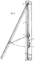
- FIG. 5 shows a shutter fitted with the device of the invention and which is of the "projection" type, that is to say that its axis of articulation is horizontal and placed in the upper part of the window frame, while in FIGS. 1 to 4, these were shutters with a vertical axis, these axes being arranged on each side of the opening.
- the references 1, 2 and 3 respectively designate the flap, the articulation, and the air spring. These parts are shown in dashes in the open position. We can see that the air spring is always oriented with the rod down, which improves its longevity thanks to the oil it contains, and which comes to lubricate the seal, as was said above.
- the references 4 and 5 designate the articulations connecting the air spring 3 respectively to the shutter 1 and to the window frame.
- the joints 4 and 5 are ball joints, and in the practical embodiment, these are plastic cage joints, with automatic snap-in to facilitate assembly, that is to say comprising a ball joint trapped in a cage, which comprises, for retaining the ball joint, a portion of elastic ring of steel or similar material, which is mounted in the housing of the cage where it can slide parallel to the central axis thereof and be further provided with two symmetrically arranged heels, of substantially frustoconical shape, so as to converge towards said axis, said housing having, in addition to the part allowing the above-mentioned sliding of the ring, bearing surfaces for the heels which they prevent from moving away from each other and releasing the patella.
- the piston rod 3 is hidden by a tube 3c, which moves telescopically on the 3d cylinder of the spring.
- This protective tube prevents any deterioration of the piston rod by the effect of shock, dirt, or during the deposition of a layer of paint.
- the air spring 3 is provided with an electrical position detection device of the type described in patent FR-A-2,571,109 in the name of the Applicant, which is adjusted to close a contact when the elongation of the air spring 3 reaches a value between that which corresponds to the closed position visible in solid lines in FIG. 5, and the open position, visible in dashes in the same figure.
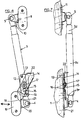
- Figures 6 and 7 show the detail of a sutomatic locking device of the shutter in the closed position.
- This device comprises: a plate 12, held by screws 13 against the flap 1.
- a blocking part 14 is forced to move vertically by sliding on the part 12, thanks to an elongated projection 15 carried by the part 12, and which cooperates with an elongated opening 16 of the part 14.
- the latter is moreover held by a head screw 17.
- the lower part of the part 14 comprises an oblique part 18, which cooperates with the fitting 19 carrying the ball joint 4 , so that when the shutter approaches the closed position, a vertical wing 20, perpendicular to the plane of the shutter, and which is part of the lock 19, lifts the part 14.
- the device which has just been described refers more particularly to the closing of shutters. It is clear that it is also applicable for other uses, such as in particular the opening and closing of window frames.
Landscapes
- Closing And Opening Devices For Wings, And Checks For Wings (AREA)
- Air-Flow Control Members (AREA)
Description
La présente invention est relative à dispositif pour l'ouverture et la fermeture d'un moyen d'obturation de baie de bâtiment du type défini dans le préambule de la revendication 1 et aussi connu du US-A-1 617771.The present invention relates to a device for opening and closing a building bay shutter means of the type defined in the preamble of
Les volets d'occultation de baies telles que portes et fenêtres sont généralement manoeuvrés à la main pour leur ouverture et leur fermeture. En position fermée, ils doivent être maintenus par un verrou convenable. En position ouverte, ils doivent être également bloqués pour éviter d'être actionnés par le vent.The blackout shutters such as doors and windows are generally operated by hand to open and close them. In the closed position, they must be held by a suitable lock. In the open position, they must also be blocked to avoid being actuated by the wind.
Classiquement, les volets sont à axe de pivotement vertical, et viennent se rabattre contre la face extérieure du mur en position d'ouverture, si bien que les dispositifs de blocage correspondants sont difficiles ou dangereux d'accès. Il existe aussi des volets à axe horizontal situés au-dessus de la baie, leur ouverture est rendue pénible par le fait qu'il faut lutter contre leur poids.Conventionally, the shutters have a vertical pivot axis, and are folded against the outside face of the wall in the open position, so that the corresponding blocking devices are difficult or dangerous to access. There are also flaps with a horizontal axis located above the bay, their opening is made painful by the fact that you have to fight against their weight.
On a proposé, dans le cas de portes à axe vertical, d'équiper celles-ci d'un dispositif comportant un ressort. Dans US-A-1.617.771, ce dispositif présente un point mort, et le ressort tend à écarter la porte du point mort pour l'entraîner soit vers la position de fermeture, soit vers une position d'ouverture, où elle est rabattue contre la face extérieure d'un mur. Un tel dispositif n'est guère utilisable pour des volets de baies de bâtiment, car le ressort, s'il était assez puissant pour résister à l'action du vent, imprimerait aux volets des vitesses de déplacement inacceptables.It has been proposed, in the case of doors with a vertical axis, to equip them with a device comprising a spring. In US-A-1.617.771, this device has a neutral position, and the spring tends to move the door from neutral to drive it either towards the closed position or towards an open position, where it is folded down against the outside face of a wall. Such a device is hardly usable for shutters of building bays, since the spring, if it was powerful enough to resist the action of the wind, would impart to the shutters unacceptable speeds of movement.
On connaît aussi, par DE-A-2.420.178 un dispositif pour l'ouverture et la fermeture d'un moyen d'obturation d'une ouverture prévue dans un plafond de bâtiment du type lucarne pour escalier escamotable, comportant un ressort constitué d'un cylindre fermé à ses deux extrémités, contenant un gaz comprimé et une certaine quantité d'huile, et dans laquelle peut se déplacer à vaet-vient un piston solidaire d'une tige qui sort de l'enceinte par un joint étanche. Dans la position ouverte de la lucarne la sortie de la tige est en partie basse du ressort pour lubrifier le joint d'étanchéité.DE-A-2,420,178 also discloses a device for opening and closing a means for closing an opening provided in a building ceiling of the skylight type for retractable staircase, comprising a spring constituted by 'a cylinder closed at both ends, containing a compressed gas and a certain amount of oil, and in which can move back and forth a piston secured to a rod which leaves the enclosure by a tight seal. In the open position of the skylight, the rod outlet is in the lower part of the spring to lubricate the seal.
Le ressort pneumatique, ou à gaz, constitué par ce cylindre avec le gaz comprimé qu'il contient et le piston avec sa tige est relié par une extrémité directement au pourtour de la baie, et, par son autre extrémité, au moyen d'obturation par l'intermédiaire d'un système de tringles articulées. Ce système de tringles est disposé de telle sorte que la position d'ouverture correspond à un point mort, où le ressort n'exerce aucun couple tendant à faire tourner le moyen d'obturation.The pneumatic spring, or gas, constituted by this cylinder with the compressed gas which it contains and the piston with its rod is connected by one end directly to the periphery of the bay, and, by its other end, by means of obturation through a system of articulated rods. This rod system is arranged so that the open position corresponds to a neutral position, where the spring exerts no torque tending to rotate the shutter means.
L'invention a pour but de fournir un dispositif à ressort pour l'ouverture et la fermeture de moyens à axe de pivotement vertical d'obturation de baies de bâtiment qui cumule les qualités de simplicité et de robustesse des dispositifs à ressort classiques avec les avantages inhérents au ressort à gaz, à savoir principalement la possibilité de combiner une force importante avec des mouvements à vitesse contrôlée et amortis en fin de course, et qui conserve ces avantages pendant une durée compatible avec les exigences du bâtiment.The object of the invention is to provide a spring device for opening and closing means with a vertical pivot axis for closing building bays which combines the simplicity and robustness qualities of conventional spring devices with the advantages inherent in the gas spring, namely mainly the possibility of combining a large force with movements at controlled speed and damped at the end of the stroke, and which retains these advantages for a period compatible with the requirements of the building.
Dans ce but, l'invention fournit un dispositif du type indiqué ci-dessus et comportant un ressort agissant en compression, articulé d'une part sur le pourtour de la baie et, d'autre part, sur le moyen d'obturation en un point écarté de l'axe de pivotement de ce moyen d'obturation, ledit ressort étant disposé de telle sorte qu'au cours de son pivotement le moyen d'obturation passe par un point mort, où les trois articulations du moyen d'obturation et du ressort sur le mur et du ressort sur le moyen d'obturation sont alignées, le ressort développant des forces qui tendent à déplacer le moyen d'obturation vers la position de fermeture ou d'ouverture quand il est en dehors du point mort, caractérisé en ce que:
- le ressort est constitué d'un cylindre fermé à ses deux extrémités, contenant un gaz comprimé et une certaine quantité d'huile, et dans laquelle peut se déplacer à vaet-vient un piston solidaire d'une tige qui sort de l'enceinte par un joint étanche,
- les points d'articulation du ressort sont disposés de telle façon que ledit ressort est incliné en permanence par rapport à l'horizontale avec la sortie de la tige en partie basse, et l'huile est maintenue près de la sortie de la tige.
- the spring consists of a cylinder closed at its two ends, containing a compressed gas and a certain amount of oil, and in which can move back and forth a piston secured to a rod which leaves the enclosure by a tight seal,
- the points of articulation of the spring are arranged in such a way that said spring is permanently inclined with respect to the horizontal with the outlet of the rod in the lower part, and the oil is kept close to the outlet of the rod.
En cherchant les causes d'échec des tentatives de transposition du ressort à gaz dans le bâtiment, les inventeurs ont en effet découvert qu'il se pose un problème de lubrification. Pour avoir une longue durée, un ressort à gaz doit contenir une certaine quantité d'huile qui doit pouvoir se rassembler sur celui des fonds du cylindre qui est traversé par la tige de piston, afin de lubrifier celle-ci. Cela est facile dans les ressorts à gaz montés sur les véhicules automobiles, où le déplacement important du hayon fait passer le ressort d'une position tête-en-haut à une position tête-en-bas, mais cela ne peut être obtenu en remplaçant purement et simplement le ressort à boudin de US-A-1.617.771, par exemple, par un ressort à gaz disposé de la même façon. En effet, dans ce brevet, le ressort à boudin est disposé horizontalement, et par conséquent, le ressort à gaz disposé de la même manière n'aurait pas sa tige lubrifiée.By looking for the causes of failure of attempts to transpose the gas spring into the building, the inventors have indeed discovered that there is a lubrication problem. To have a long life, a gas spring must contain a certain quantity of oil which must be able to collect on that of the bottoms of the cylinder which is crossed by the piston rod, in order to lubricate this latter. This is easy in gas springs mounted on motor vehicles, where the large displacement of the tailgate moves the spring from a head-up position to a head-down position, but this cannot be achieved by replacing purely and simply the coil spring of US-A-1,617,771, for example, by a gas spring arranged in the same way. In fact, in this patent, the coil spring is arranged horizontally, and consequently, the gas spring arranged in the same way would not have its rod lubricated.
Au contraire, dans les techniques du bâtiment, il est nécessaire que le ressort à gaz soit constamment orienté de telle façon que l'huile soit en contact avec la tige, du fait que le moyen d'obturation peut rester en position d'ouverture ou de fermeture pendant de très longues périodes.On the contrary, in building techniques, it is necessary for the gas spring to be constantly oriented in such a way that the oil is in contact with the rod, since the shutter means can remain in the open position or closing for very long periods.
De préférence, lorsque le moyen d'obturation constitue un volet à axe de pivotement vertical, le ressort pneumatique est articulé sur le linteau de la baie.Preferably, when the shutter means constitutes a flap with a vertical pivot axis, the res pneumatic spell is articulated on the lintel of the bay.
Suivant une modalité préférée, le ressort pneumatique est articulé sur le moyen d'obturation et sur le pourtour de la baie par l'intermédiaire d'articulations à rotule, qui sont, de préférence, du type à cages en matière plastique. L'avantage de cette disposition est qu'il est possible de tolérer un gauchissement tel qu'il peut se produire après un usage prolongé, sans aucune gêne pour le fonctionnement du dispositif. Dans le cas d'une telle déformation, le point mort dont il a été question plus haut est celui où la droite joignant les centres des articulations sphériques rencontre la droite qui constitue l'axe de l'articulation du volet sur le cadre de la baie. Suivant une modalité avantageuse, il est prévu qu'au moins un ressort pneumatique est pourvu d'un détecteur de position qui peut être relié à des moyens capables de donner l'alarme en cas d'ouverture non désirée.According to a preferred method, the air spring is articulated on the closure means and on the periphery of the opening by means of ball joints, which are preferably of the plastic cage type. The advantage of this arrangement is that it is possible to tolerate warping such as it can occur after prolonged use, without any discomfort for the operation of the device. In the case of such a deformation, the dead center mentioned above is that where the straight line joining the centers of the spherical articulations meets the straight line which constitutes the axis of the articulation of the flap on the frame of the opening. . According to an advantageous arrangement, it is provided that at least one pneumatic spring is provided with a position detector which can be connected to means capable of giving the alarm in the event of unwanted opening.
Cette modalité permet de se dispenser de poser des détecteurs spéciaux, très visibles, et, par conséquent, faciles à neutraliser.This modality makes it possible to dispense with installing special detectors, very visible, and therefore easy to neutralize.
Suivant une autre modalité intéressante, le ressort pneumatique peut être du type blocable dans une position intermédiaire, et comportant pour cela une valve qui ouvre ou ferme la communication entre les deux faces du piston, ce qui permet d'arrêter le moyen d'obturation au degré d'ouverture qu'on désire.According to another advantageous modality, the pneumatic spring can be of the lockable type in an intermediate position, and comprising for this a valve which opens or closes the communication between the two faces of the piston, which makes it possible to stop the means of obturation at degree of openness you want.
D'autres modes particuliers de réalisation apparaissent dans les autres revendications dépendantes.Other particular embodiments appear in the other dependent claims.
La présente invention va maintenant être décrite de façon plus détaillée a l'aide d'exemples pratiques illustrés à l'aide des figures parmi lesquelles:
- Figures 1 et 2 sont des vues en élévation et en coupe horizontale de volets de fenêtre du type traditionnel à axe de pivotement vertical équipé d'un ressort pneumatique conformément à l'invention.
- Figure 3 est une coupe horizontale à plus grande échelle montrant le détail, des articulations d'un des ressorts pneumatiques.
- Figure 4 est une vue en élévation correspondant à la figure 3.
- Figure 5 est une vue en coupe verticale d'une fenêtre équipée d'un volet pivotant sur un axe horizontal, et équipé d'un dispositif conforme à l'invention.
- Figure 6 est une vue agrandie d'une partie de la figure 5.
- Figure 7 est une vue de l'objet de la figure 5, suivant une direction perpendiculaire, avec coupe partielle.
- Figures 1 and 2 are views in elevation and in horizontal section of window shutters of the traditional type with vertical pivot axis equipped with a pneumatic spring according to the invention.
- Figure 3 is a horizontal section on a larger scale showing the detail of the joints of one of the air springs.
- Figure 4 is an elevational view corresponding to Figure 3.
- Figure 5 is a vertical sectional view of a window equipped with a pivoting flap on a horizontal axis, and equipped with a device according to the invention.
- Figure 6 is an enlarged view of part of Figure 5.
- Figure 7 is a view of the object of Figure 5, in a perpendicular direction, with partial section.
Comme on le voit sur les figures 1 et 2, à chacun des volets 1 d'une fenêtre, qui sont articulés par des gonds 2 sur le bâti de la fenêtre, est associé un ressort pneumatique 3 rempli de gaz sous pression et tendant constamment à l'extension. Chacun des ressorts 3 est articulé, d'une part, en 4 aur le volet et, d'autre part, en 5 sur le linteau de la baie. L'articulation 4 sur le volet est prévue sur une ferrure 6 fixée au volet, de manière que cette articulation 4 soit à une certaine distance de la ligne des gonds 2 du volet, ligne autour de laquelle se fait la rotation de celui-ci.As seen in Figures 1 and 2, each of the
On crée ainsi un bras de levier déterminant le moment du couple auquel le volet est soumis par le ressort pneumatique et on le choisira en fonction de la poussée exercée par ce ressort pour obtenir la meilleure action. On peut d'ailleurs remarquer que, dans le pivotement du volet, l'articulation 4 décrit l'arc de cercle 7 dont le rayon doit être compatible avec les possibilités d'extension et le raccourcissement du ressort pneumatique.This creates a lever arm determining the moment of the torque to which the flap is subjected by the pneumatic spring and will be chosen according to the thrust exerted by this spring to obtain the best action. It may also be noted that, in the pivoting of the flap, the
On observe aussi, en examinant la figure 3, que dans le pivotement du volet, il existe une position intermédiaire représentée en traits interrompus pourla- quelle les trois articulations 2, 4 et 5 sont alignées (figure 3 en, donnant une position de point mort.We also observe, by examining FIG. 3, that in the pivoting of the flap, there is an intermediate position represented in broken lines for which the three
D'un côté de cette position, la poussée du ressort pneumatique tend à déterminer l'ouverture complète du volet qui est bloqué contre le mur d'une manière permanente à la fin de l'ouverture (position représentée en traits pleins sur la figure 3). Au contraire, de l'autre côté de cette position, la poussée du ressort tend à fermer le volet et à le maintenir fermé (position représentée en traits mixtes à la partie supérieure de la figure 3).On one side of this position, the air spring thrust tends to determine the complete opening of the shutter which is locked against the wall permanently at the end of the opening (position shown in solid lines in Figure 3 ). On the contrary, on the other side of this position, the thrust of the spring tends to close the shutter and keep it closed (position shown in phantom in the upper part of FIG. 3).
Les manoeuvres d'ouverture et de fermeture des volets sont ainsi simplifiées à l'extrême, puisqu'il suffit à l'utilisateur d'amorcer à la main l'ouverture ou la fermeture, les ressorts pneumatiques se chargeant de la suite d'une façon automatique. Pour amorcer la manoeuvre des volets, on munira chacun d'eux d'une poignée 8 placée à l'endroit le plus commode.The maneuvers for opening and closing the shutters are thus simplified to the extreme, since it suffices for the user to initiate the opening or closing by hand, the air springs being responsible for following a automatically. To start the operation of the shutters, each of them will be provided with a
On peut noter que du fait de la temporisation de l'égalisation des pressions de part et d'autre du piston du ressort pneumatique, les mouvements se font sans brusquerie. La temporisation peut d'ailleurs être adaptée aux besoins par le réglage de passages calibrés entre les faces du piston.It can be noted that due to the timing of the equalization of the pressures on either side of the piston of the air spring, the movements are made without abruptness. The time delay can also be adapted to requirements by adjusting calibrated passages between the faces of the piston.
On remarque aussi que les ressorts pneumatiques sont disposés à la partie supérieure de la baie, de sorte qu'ils sont peu apparents.We also note that the air springs are arranged at the top of the opening, so that they are not very visible.
On voit sur les figures 1 et 4 la position inclinée des ressorts pneumatiques entre leurs articulations 4 et 5. Cette inclinaison est utile pour garantir la douceur du mouvement d'ouverture à partir du dépassement du point mort, quand le ressort pneumatique contient une certaine quantité d'huile qui amortit le mouvement du piston à la fin de la course d'extension. L'inclinaison du ressort pneumatique maintient en effet cette huile près de la sortie de tige, où elle a aussi pour rôle de lubrifier en permanence le joint d'étanchéité qui est ainsi plus durable, comme cela a été exposé auparavant.We see in Figures 1 and 4 the inclined position of the air springs between their
Comme on le voit sur les figures 3 et 4, la tige 3a du piston 3b représentée en pointillés peut être cachée par un tube 3c se déplaçant télescopiquement sur le cylindre 3d du ressort, dans lequel se meut le piston.As seen in Figures 3 and 4, the rod 3a of the piston 3b shown in dotted lines can be hidden by a
Les ressorts pneumatiques peuvent être du type blocable dans une position intermédiaire et comporter pour cela une valve, ouvrant ou fermant la communication entre, les deux faces du piston, ce qui permet d'arrêter les volets à mi-ouverture si on le désire.The pneumatic springs can be of the lockable type in an intermediate position and for this purpose comprise a valve, opening or closing the communication between, the two faces of the piston, which makes it possible to stop the flaps at mid-opening if desired.
Ils peuvent aussi être associés à un contacteur électrique déclenché dans la course d'ouverture des volets pour actionner un dispositif d'alarme.They can also be associated with an electrical contactor triggered in the shutter opening stroke to activate an alarm device.
La figure 5 monte un volet équipé du dispositif de l'invention et qui est du type "à projection", c'est-à-dire que son axe d'articulation est horizontal et placé en partie haute du cadre de fenêtre, alors que dans les figures 1 à 4 il s'agissait de volets à axe vertical, ces axes étant disposés de chaque côté de la baie.FIG. 5 shows a shutter fitted with the device of the invention and which is of the "projection" type, that is to say that its axis of articulation is horizontal and placed in the upper part of the window frame, while in FIGS. 1 to 4, these were shutters with a vertical axis, these axes being arranged on each side of the opening.
Les repères 1, 2 et 3 désignent respectivement le volet, l'articulation, et le ressort pneumatique. On a représenté en tirets ces pièces dans la position d'ouverture. On peut voir que le ressort pneumatique est toujours orienté avec la tige vers le bas, ce qui améliore sa longévité grâce à l'huile qu'il contient, et qui vient lubrifier le joint, comme il a été dit plus haut. Les repères 4 et 5 désignent les articulations reliant le ressort pneumatique 3 respectivement au volet 1 et au bâti de la fenêtre. Les articulations 4 et 5 sont des articulations à rotule, et dans la réalisation pratique, il s'agit d'articulations à cage en matière plastique, à encliquetage automatique pourfaciliter le le montage, c'est-à-dire comportant une rotule emprisonnée dans une cage, laquelle comporte, pour la retenue de la rotule, une portion d'anneau élastique en acier ou matériau analogue, qui est montée dans le logement de la cage où elle peut coulisser parallèlement à l'axe central de celle-ci et être en outre munie de deux talons symétriquement disposés, de forme sensiblement tronconique, de manière à converger vers ledit axe, ledit logement présentant, en plus de la partie permettant le coulissement susdit de l'anneau, des surfaces de portée pour les talons qu'elles empêchent de s'écarter l'une de l'autre et de libérer la rotule.The
L'avantage de ces articulations à rotule par rapport à des articulations comportant un simple axe de pivotement du type classique et que, si un gauchissement fait que, en considérant la figure 7, les axes des articulations 4 et 5 ne se trouvent pas sur la même verticale, il n'en résulte aucun frottement supplémentaire, et que le fonctionnement est toujours satisfaisant.The advantage of these ball joints compared to joints comprising a simple pivot axis of the conventional type and that, if a warping means that, considering FIG. 7, the axes of
Comme on peut le voir sur les figures 6 et 7, la tige du piston 3 est cachée par un tube 3c, qui se déplace télescopiquement sur le cylindre 3d du ressort. Ce tube de protection évite toute détérioration de la tige de piston par l'effet de choc, de salissure, ou à l'occasion du dépôt d'une couche de peinture.As can be seen in Figures 6 and 7, the
Des trous 3e percés à sa base évitent l'accumulation de l'eau à l'intérieur de ce tube.3rd holes drilled at its base prevent the accumulation of water inside this tube.
Le ressort pneumatique 3 est pourvu d'un dispositif de détection électrique de position du type décrit au brevet FR-A-2.571.109 au nom de la Demanderesse, qui est réglé pour fermer un contact lorsque l'allongement du ressort pneumatique 3 atteint une valeur comprise entre celle qui correspond à la position de fermeture visible en trait plein à la figure 5, et la position d'ouverture, visible en tirets sur la même figure.The
On a représenté en 10, à la figure 6, le câble électrique de sortie du ressort pneumatique 3. On constate que ce câble est peu visible et peut être en pratique complètement caché derrière la ferrure 11 qui supporte l'articulation 5.FIG. 6 shows the electrical cable for the output of the pneumatic spring at FIG. 6. It can be seen that this cable is not very visible and can in practice be completely hidden behind the fitting 11 which supports the joint 5.
Les figures 6 et 7 montrent le détail d'un dispositif de verrouillage sutomatique du volet en position de fermeture. Ce dispositif comprend: une platine 12, maintenue par des vis 13 contre le volet 1. Une pièce de blocage 14 est astreinte à se déplacer verticalement en coulissant sur la pièce 12, gràce à une saillie allongée 15 portée par la pièce 12, et qui coopère avec une ouverture allongée 16 de la pièce 14. Cette dernière est par ailleurs maintenue par une vis à tête 17. La partie inférieure de la pièce 14 comprend une partie oblique 18, qui coopère avec la ferrure 19 portant l'articulation à rotule 4, de telle sorte que lorsque le volet s'approche de la position de fermeture, une aile verticale 20, perpendiculaire au plan du volet, et qui fait partie de la serrure 19, soulève la pièce 14. Lorsque le volet atteint la position de fermeture, l'aile 20 dépasse l'extrémité de la partie oblique 18, et la pièce 14 retombe, empêchant le volet de s'écarter de la position de fermeture, grâce à une surface verticale 21 qui vient porter sur la face opposée de l'aile 20.Figures 6 and 7 show the detail of a sutomatic locking device of the shutter in the closed position. This device comprises: a
Si l'on désire ouvrir à nouveau le volet, il suffit de relever manuellement la pièce 14. Celle-ci comporte une aile repliée à l'horizontale 22, qui facilite cette opération.If one wishes to open the shutter again, it suffices to manually raise the
Le dispositif qui vient d'être décrit se réfère plus particulièrement à la fermeture de volets. Il est clair qu'il est également applicable pour d'autres usages, tels notamment l'ouverture et la fermeture de châssis vitrés.The device which has just been described refers more particularly to the closing of shutters. It is clear that it is also applicable for other uses, such as in particular the opening and closing of window frames.
Claims (8)
Priority Applications (1)
| Application Number | Priority Date | Filing Date | Title |
|---|---|---|---|
| AT86401883T ATE53430T1 (en) | 1985-08-29 | 1986-08-27 | DEVICE FOR OPENING AND CLOSING BUILDING OPENINGS BY SPRING FORCE. |
Applications Claiming Priority (4)
| Application Number | Priority Date | Filing Date | Title |
|---|---|---|---|
| FR8512875A FR2586745B1 (en) | 1985-08-29 | 1985-08-29 | PNEUMATIC SPRING DEVICE FOR OPENING AND CLOSING SHUTTERS OF BUILDING BAYS |
| FR8512875 | 1985-08-29 | ||
| FR8518757 | 1985-12-18 | ||
| FR8518757A FR2591651B2 (en) | 1985-12-18 | 1985-12-18 | PNEUMATIC SPRING DEVICE FOR OPENING AND CLOSING SHUTTERS OF BUILDING BAYS |
Publications (3)
| Publication Number | Publication Date |
|---|---|
| EP0216680A1 EP0216680A1 (en) | 1987-04-01 |
| EP0216680B1 EP0216680B1 (en) | 1990-06-06 |
| EP0216680B2 true EP0216680B2 (en) | 1993-03-31 |
Family
ID=26224692
Family Applications (1)
| Application Number | Title | Priority Date | Filing Date |
|---|---|---|---|
| EP19860401883 Expired - Lifetime EP0216680B2 (en) | 1985-08-29 | 1986-08-27 | Spring device for opening and closing shutter means for door or window openings |
Country Status (2)
| Country | Link |
|---|---|
| EP (1) | EP0216680B2 (en) |
| DE (1) | DE3671777D1 (en) |
Families Citing this family (4)
| Publication number | Priority date | Publication date | Assignee | Title |
|---|---|---|---|---|
| FR2638779A1 (en) * | 1988-11-10 | 1990-05-11 | Vernois Goulven | Device for manoeuvring, simultaneously or otherwise, manually or using a motor, the two shutters of a building opening |
| FR2651528A2 (en) * | 1988-11-10 | 1991-03-08 | Vernois Goulven | Device for operating and locking the shutters of a bay of a building |
| US5458962A (en) * | 1993-08-11 | 1995-10-17 | Minnesota Mining And Manufacturing Company | Nonwoven surface treating articles and methods of making and using same |
| DE202006003197U1 (en) * | 2006-03-01 | 2007-07-12 | Hettich-Oni Gmbh & Co. Kg | Damper for furniture |
Family Cites Families (5)
| Publication number | Priority date | Publication date | Assignee | Title |
|---|---|---|---|---|
| US1617771A (en) * | 1926-05-05 | 1927-02-15 | Dent Hardware Company | Door closer |
| US3698464A (en) * | 1968-08-02 | 1972-10-17 | Bus & Car Co Sa | Folding door for luggage compartment of vehicles such as motor-coaches for example |
| GB1423832A (en) * | 1972-04-11 | 1976-02-04 | Bloxvich Lock Stamping | Telescopic stays |
| DE2420178A1 (en) * | 1974-04-26 | 1975-11-13 | Agro Grebe Kg | Lock for trap door combined with ladder - consists of pneumatic spring connected to articulated trap door hinge mechanism |
| US4471575A (en) * | 1982-12-27 | 1984-09-18 | Stout Gerald T | Door closer |
-
1986
- 1986-08-27 DE DE8686401883T patent/DE3671777D1/en not_active Expired - Fee Related
- 1986-08-27 EP EP19860401883 patent/EP0216680B2/en not_active Expired - Lifetime
Also Published As
| Publication number | Publication date |
|---|---|
| DE3671777D1 (en) | 1990-07-12 |
| EP0216680B1 (en) | 1990-06-06 |
| EP0216680A1 (en) | 1987-04-01 |
Similar Documents
| Publication | Publication Date | Title |
|---|---|---|
| EP2489536B1 (en) | Door system for a motor vehicle, in particular for an automobile. | |
| FR2886612A1 (en) | DEVICE FOR CONTROLLING THE OPENING OF THE COVER OF A VEHICLE, IN PARTICULAR FOR PROTECTING THE HEAD OF A PIECE IN THE EVENT OF SHOCK. | |
| EP0216680B2 (en) | Spring device for opening and closing shutter means for door or window openings | |
| EP1369276A1 (en) | Rear bootlid for automobile | |
| FR3087414A1 (en) | AIRCRAFT DOOR WITH ADDITIONAL SAFETY LIFTING | |
| EP1595051A1 (en) | Hinge device for a door leaf | |
| FR2758522A1 (en) | DOOR SYSTEM, PARTICULARLY FOR A PASSENGER AIRCRAFT | |
| EP0319357B1 (en) | Fume extraction outlet or similar roof opening with large displacement of the closing panel | |
| FR2586745A1 (en) | Pneumatic-spring device for opening and closing the shutters of building apertures | |
| FR3053026A1 (en) | ASSEMBLY FOR AN AIRCRAFT COMPRISING A FIXED STRUCTURE AND A NACELLE COMPRISING A HOOD | |
| FR2522716A1 (en) | Folding door for garage - comprises upper and lower panels pivotally interconnected about horizontal axis | |
| FR2894610A1 (en) | DEVICE FOR OPENING AND CLOSING A VA-AND-VIENT DOOR VANTAIL | |
| WO2006085025A1 (en) | Vehicle with an opening the movements of which are secured by a lost motion body | |
| FR2679591A1 (en) | ELECTROMECHANICAL CONTROL DEVICE FOR A TILTING DOOR, IN PARTICULAR A GARAGE TILTING DOOR. | |
| FR2723182A1 (en) | VERTICAL REFRIGERATOR WITH IMPROVED DOOR CLOSURE | |
| EP0477068B1 (en) | Exhaust system for building façades | |
| FR2744483A1 (en) | Up-and-over garage door with obstacle crush-prevention feature | |
| EP2255702A1 (en) | Pivoting table | |
| EP0681080B1 (en) | Check device for wings | |
| FR2802570A1 (en) | Automobile bodywork protection, for opening door, comprises shock absorber component installed on panel which projects when panel opens and is retracted into housing when panel closes | |
| FR2591651A2 (en) | Device with a pneumatic spring for opening and closing opening shutters of buildings | |
| FR2739651A1 (en) | Dropping lock for tilting door of garage | |
| BE1003725A3 (en) | Arrangement for opening and closing a mobile vehicle door, such as apassenger vehicle | |
| EP0555129A1 (en) | Automatically closing trap door | |
| FR2763093A1 (en) | AUTOMATIC RETRACTABLE GASKET FOR DOOR |
Legal Events
| Date | Code | Title | Description |
|---|---|---|---|
| PUAI | Public reference made under article 153(3) epc to a published international application that has entered the european phase |
Free format text: ORIGINAL CODE: 0009012 |
|
| AK | Designated contracting states |
Kind code of ref document: A1 Designated state(s): AT BE CH DE FR GB IT LI LU NL SE |
|
| 17P | Request for examination filed |
Effective date: 19870916 |
|
| 17Q | First examination report despatched |
Effective date: 19881103 |
|
| GRAA | (expected) grant |
Free format text: ORIGINAL CODE: 0009210 |
|
| AK | Designated contracting states |
Kind code of ref document: B1 Designated state(s): AT BE CH DE FR GB IT LI LU NL SE |
|
| REF | Corresponds to: |
Ref document number: 53430 Country of ref document: AT Date of ref document: 19900615 Kind code of ref document: T |
|
| GBT | Gb: translation of ep patent filed (gb section 77(6)(a)/1977) | ||
| REF | Corresponds to: |
Ref document number: 3671777 Country of ref document: DE Date of ref document: 19900712 |
|
| ITF | It: translation for a ep patent filed |
Owner name: STUDIO CONS. BREVETTUALE S.R.L. |
|
| PLBI | Opposition filed |
Free format text: ORIGINAL CODE: 0009260 |
|
| 26 | Opposition filed |
Opponent name: ROTO FRANK AKTIENGESELLSCHAFT Effective date: 19910306 |
|
| NLR1 | Nl: opposition has been filed with the epo |
Opponent name: ROTO FRANK AG. |
|
| ITTA | It: last paid annual fee | ||
| PGFP | Annual fee paid to national office [announced via postgrant information from national office to epo] |
Ref country code: AT Payment date: 19920813 Year of fee payment: 7 |
|
| PGFP | Annual fee paid to national office [announced via postgrant information from national office to epo] |
Ref country code: SE Payment date: 19920817 Year of fee payment: 7 |
|
| PGFP | Annual fee paid to national office [announced via postgrant information from national office to epo] |
Ref country code: CH Payment date: 19920826 Year of fee payment: 7 |
|
| PG25 | Lapsed in a contracting state [announced via postgrant information from national office to epo] |
Ref country code: SE Effective date: 19920828 |
|
| PGFP | Annual fee paid to national office [announced via postgrant information from national office to epo] |
Ref country code: NL Payment date: 19920831 Year of fee payment: 7 |
|
| PGFP | Annual fee paid to national office [announced via postgrant information from national office to epo] |
Ref country code: LU Payment date: 19920903 Year of fee payment: 7 |
|
| PGFP | Annual fee paid to national office [announced via postgrant information from national office to epo] |
Ref country code: BE Payment date: 19920930 Year of fee payment: 7 |
|
| EPTA | Lu: last paid annual fee | ||
| PUAH | Patent maintained in amended form |
Free format text: ORIGINAL CODE: 0009272 |
|
| STAA | Information on the status of an ep patent application or granted ep patent |
Free format text: STATUS: PATENT MAINTAINED AS AMENDED |
|
| 27A | Patent maintained in amended form |
Effective date: 19930331 |
|
| AK | Designated contracting states |
Kind code of ref document: B2 Designated state(s): AT BE CH DE FR GB IT LI LU NL SE |
|
| PG25 | Lapsed in a contracting state [announced via postgrant information from national office to epo] |
Ref country code: NL Effective date: 19930331 |
|
| GBTA | Gb: translation of amended ep patent filed (gb section 77(6)(b)/1977) |
Effective date: 19930310 |
|
| REG | Reference to a national code |
Ref country code: CH Ref legal event code: AEN |
|
| NLR2 | Nl: decision of opposition | ||
| ITF | It: translation for a ep patent filed |
Owner name: STUDIO CONS. BREVETTUALE S.R.L. |
|
| PG25 | Lapsed in a contracting state [announced via postgrant information from national office to epo] |
Ref country code: AT Effective date: 19930630 |
|
| PG25 | Lapsed in a contracting state [announced via postgrant information from national office to epo] |
Ref country code: LU Free format text: LAPSE BECAUSE OF NON-PAYMENT OF DUE FEES Effective date: 19930827 |
|
| PG25 | Lapsed in a contracting state [announced via postgrant information from national office to epo] |
Ref country code: LI Effective date: 19930831 Ref country code: CH Effective date: 19930831 Ref country code: BE Effective date: 19930831 |
|
| NLV1 | Nl: lapsed or annulled due to failure to fulfill the requirements of art. 29p and 29m of the patents act | ||
| BERE | Be: lapsed |
Owner name: AIRAX Effective date: 19930831 |
|
| REG | Reference to a national code |
Ref country code: CH Ref legal event code: PL |
|
| EUG | Se: european patent has lapsed |
Ref document number: 86401883.3 Effective date: 19930716 |
|
| PGFP | Annual fee paid to national office [announced via postgrant information from national office to epo] |
Ref country code: FR Payment date: 19980814 Year of fee payment: 13 |
|
| PGFP | Annual fee paid to national office [announced via postgrant information from national office to epo] |
Ref country code: GB Payment date: 19980818 Year of fee payment: 13 |
|
| PGFP | Annual fee paid to national office [announced via postgrant information from national office to epo] |
Ref country code: DE Payment date: 19980907 Year of fee payment: 13 |
|
| PG25 | Lapsed in a contracting state [announced via postgrant information from national office to epo] |
Ref country code: GB Free format text: LAPSE BECAUSE OF NON-PAYMENT OF DUE FEES Effective date: 19990827 |
|
| GBPC | Gb: european patent ceased through non-payment of renewal fee |
Effective date: 19990827 |
|
| PG25 | Lapsed in a contracting state [announced via postgrant information from national office to epo] |
Ref country code: FR Free format text: LAPSE BECAUSE OF NON-PAYMENT OF DUE FEES Effective date: 20000428 |
|
| PG25 | Lapsed in a contracting state [announced via postgrant information from national office to epo] |
Ref country code: DE Free format text: LAPSE BECAUSE OF NON-PAYMENT OF DUE FEES Effective date: 20000601 |
|
| REG | Reference to a national code |
Ref country code: FR Ref legal event code: ST |
|
| PG25 | Lapsed in a contracting state [announced via postgrant information from national office to epo] |
Ref country code: IT Free format text: LAPSE BECAUSE OF NON-PAYMENT OF DUE FEES;WARNING: LAPSES OF ITALIAN PATENTS WITH EFFECTIVE DATE BEFORE 2007 MAY HAVE OCCURRED AT ANY TIME BEFORE 2007. THE CORRECT EFFECTIVE DATE MAY BE DIFFERENT FROM THE ONE RECORDED. Effective date: 20050827 |