EP0207229A2 - Illumination system of the digital control type - Google Patents
Illumination system of the digital control type Download PDFInfo
- Publication number
- EP0207229A2 EP0207229A2 EP86104289A EP86104289A EP0207229A2 EP 0207229 A2 EP0207229 A2 EP 0207229A2 EP 86104289 A EP86104289 A EP 86104289A EP 86104289 A EP86104289 A EP 86104289A EP 0207229 A2 EP0207229 A2 EP 0207229A2
- Authority
- EP
- European Patent Office
- Prior art keywords
- image
- illumination
- light
- video signal
- color
- Prior art date
- Legal status (The legal status is an assumption and is not a legal conclusion. Google has not performed a legal analysis and makes no representation as to the accuracy of the status listed.)
- Granted
Links
Images


Classifications
-
- B—PERFORMING OPERATIONS; TRANSPORTING
- B25—HAND TOOLS; PORTABLE POWER-DRIVEN TOOLS; MANIPULATORS
- B25J—MANIPULATORS; CHAMBERS PROVIDED WITH MANIPULATION DEVICES
- B25J9/00—Programme-controlled manipulators
- B25J9/16—Programme controls
- B25J9/1694—Programme controls characterised by use of sensors other than normal servo-feedback from position, speed or acceleration sensors, perception control, multi-sensor controlled systems, sensor fusion
- B25J9/1697—Vision controlled systems
-
- B—PERFORMING OPERATIONS; TRANSPORTING
- B25—HAND TOOLS; PORTABLE POWER-DRIVEN TOOLS; MANIPULATORS
- B25J—MANIPULATORS; CHAMBERS PROVIDED WITH MANIPULATION DEVICES
- B25J19/00—Accessories fitted to manipulators, e.g. for monitoring, for viewing; Safety devices combined with or specially adapted for use in connection with manipulators
- B25J19/02—Sensing devices
- B25J19/04—Viewing devices
-
- G—PHYSICS
- G06—COMPUTING; CALCULATING OR COUNTING
- G06V—IMAGE OR VIDEO RECOGNITION OR UNDERSTANDING
- G06V10/00—Arrangements for image or video recognition or understanding
- G06V10/10—Image acquisition
- G06V10/12—Details of acquisition arrangements; Constructional details thereof
- G06V10/14—Optical characteristics of the device performing the acquisition or on the illumination arrangements
- G06V10/143—Sensing or illuminating at different wavelengths
-
- G—PHYSICS
- G06—COMPUTING; CALCULATING OR COUNTING
- G06V—IMAGE OR VIDEO RECOGNITION OR UNDERSTANDING
- G06V10/00—Arrangements for image or video recognition or understanding
- G06V10/10—Image acquisition
- G06V10/12—Details of acquisition arrangements; Constructional details thereof
- G06V10/14—Optical characteristics of the device performing the acquisition or on the illumination arrangements
- G06V10/145—Illumination specially adapted for pattern recognition, e.g. using gratings
Definitions
- the present invention relates to an illumination system of the digital control type for use in, e.g., a visual system of an industrial robot or the like.
- an illumination system of the digital control type comprises: an image memory for storing the data regarding a predetermined illumination pattern; video signal producing means for reading out the data from the image memory and converting them into a video signal representative of the illumination pattern; and light irradiating means for irradiating the light of the illumination pattern represented by the video signal to an object to be illuminated.
- the data regarding the illumination pattern of each color component of the color illumination light is stored into the image memory, respectively, for every color components, e.g., three primary colors.
- the video signal is produced for each clor component.
- the illumination pattern light of each color component is projected from the light irradiating means. The lights of the color components projected are synthesized and irradiated onto the object.
- an arbitrary illumination pattern can be formed in the image memory and the illumination pattern formed can be also moved in the image memory under control of a computer. Therefore, the illumination pattern can be scanned without using any mechanical movable part aria the foregoing various problems which are caused due to the presence of the movable parts can be solved.
- Various kinds of specifications of the illumination light such as the shape, size, brightness, etc. of the illumination pattern which are required by the industrial visual system can be easily set and controlled by the softwares.
- the illumination pattern can be stored or reproduced at a high speed with a high degree of fidelity.
- F ig. 1 shows an outline of an electrical arrangement of an illumination system of the digital control type.
- This illumination system is controlled by a computer system 4 comprising: a central processing unit (CPU) 1; a program memory 2 in which programs necessary to control the illumination are stored; and a data memory 3.
- An interface 5, which is connected to other external apparatus such as, e.g., a control system of a robot or the like, and an auxiliary memory 6 are also connected to the computer system 4 through a bus including an address bus, a control bus, and a data bus.
- the illumination system can perform the color illumination and is provided with image memories 11, 12, and 13 to respectively store the data regarding illumination patterns of the respective color components of three primary colors, i.e., red, green, and bule serving as fundamental colors to synthesize an arbitrary color.
- the image memories 11 to 13 are also connected to the CPU 1 through the bus.
- the CPU 1 can directly access the image memories 11 to 13 and control the writing or storing of image patterns (illumination patterns) into the image memories, production and movement of the illumination patterns in the image memories, and readout of the data indicative of the illumination patterns from the image memories. Consequently, the production of an arbitrary illumination pattern, setting of the size, brightness, position, and the like of this pattern, and scanning thereof can be freely executed in accordance with programs (softwares) cf the CUP 1.
- the data regarding the illumination patterns read out from the image memories 11 to 13 are sent to video signal producing circuits 21, 22, and 23, from which the video signals representative of the illumination patterns are outputted, respectively.
- the video signals indicative of the red, green, and blue illumination patterns produced are sent to video projectors 31, 32, and 33, respectively.
- the lights corresponding to the red, green, and blue illumination patterns are projected frcm the video projectors 31 to 33 toward an object to be illuminated.
- a video projector receives the video signal and outputs the image projection light representative of this video signal.
- the color video projector it is constituted by three high luminance tubes (Cathode Ray Tubes), three sets of lenses disposed in front of those tubes, and a video signal processor to control the high liminance tubes.
- Fig. 1 conveniently shows the arrangement on the assumption that the video projector is provided for each color component of three primary colors.
- the lights generated from the video projectors 31 to 33 are synthesized in the space between the projectors and the object to be illuminated, so that the object is illuminated by the synthesized color illumination pattern.
- Figs. 2A and 2B show the relation between the illumination pattern (image pattern) in the image memory (Fig. 2A) and the illumination pattern projected using the data of the image pattern in the illumination area (Fig. 2 B ).
- a spot illumination light m l is projected into the illumination area in correspondence to the image M 1 .
- the spot light m 1 in the illumination area is also moved in the direction indicated by an arrow a.
- the movement of the image M 1 in the image memory is realized by, for example, erasing the data at the original position and then writing the data of the image M 1 at a new position. It will be obviously understood that when the image M 1 in the image memory is moved in the direction indicated by an arrow B different from the arrow A, on the other hand, the spot light m 1 in the illumination area is also moved in the direction indicated by an arrow b in correspondence to the arrow B.
- F ig. 3 shows an image M 2 for another illumination pattern stored in the image memory. It will be easily appreciated that the slit-like illumination light is irradiated into the illumination area due to the image M 2 and when the image M 2 is moved in the direction indicated by an arrow in the image memory, the slit-like illumination pattern in the illumination area is also moved in the direction corresponding to this arrow.
- a lattice image pattern M 3 as shown in Fig. 4 is produced in the image memory, a similar lattice illumination pattern is also formed in the illumination area.
- an image pattern M 4 of a figure as shown in Fig. 5 is formed in the image memory, an illumination pattern of a similar figure is also formed in the illumination area.
- the enlargements reduction, rotation, parallel movement, and the like of various kinds of patterns can be freely executed due to the softwares.
- the data indicative of the image patterns can be stored as files into the auxiliary memory 6 in Fig. 1 and read out and reproduced therefrom at any time.
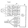
- Figs. 6 to 8 show an example of application of the illumination system of the digital control type described above. This example is suitable to perform the illumination having the emphasized contrast between the object and the background.
- FIG. 6 the same parts and components at those shown in Fig. 1 are designated by the same reference numerals.
- An illuminating unit 20 has a constitution similar to the illumination system shown in Fig. 1 exclusing that the computer system 4 was removed therefrom.
- the video signal producing circuits are not shown in Fig. 6 for simplicity of the drawing.
- the illumination data such that the lights projected from the video projectors 31 to33 are synthesized to produce white light I w is stored in the image memories 11 to 13. All of the pixel data in the respective image memories are equally set so as to project the uniform lights.
- the lights reflected frcm the surface of the object illuminated by the white light are picked up by a color television camera 40.
- the video signal is produced by the camera 40 and separated into three video signals corresponding three primary colors.
- the data indicative of the video signals of the respective colors is stored into image memories 41, 42, and 43.
- An image processing system 25 includes a CUP, a program memory, a data memory, and the like and executes the following analyzing processes of the image data of the object stored in the image memories 41 to 43. Then, the image processing system 25 sets new data into the image memories 11 to 13.
- the image processing system 25 first produces histograms H R , H G , and H B regarding the brightnesses of the image data of red, green, and blue as three primary colors of the object which has been stored in the image memories 41 to 43.
- Figs. 7A to 7C show examples of the histograms of the brightnesses of the object with respect to three primary colors.
- an axis of abscissa denotes an intensity (brightness)
- an axis of ordinate represents a frequency (number of pixels having same brightness).
- the intensities b R , b G , and b B each having the maximum frequency (peak value) are obtained from these histograms.
- the representative vectors (r R y r G , r B ) indicative of the colors of the object are calculated using the values, of intensities b R , b G , and b B by the following expressions.
- the lights are projected to the object from the video projectors 31 to 33 on the basis of the data newly set into the image memories 11 to 13.
- the color of the synthesized light I N of the projected lights from the projectors 31 to 33 is substantially the same as that of the surface of the object. Namely, since the light having almost the same color as that of the surface of the object is projected, the contrast between the object and the background is enhanced.
- Fig. 8A shows a vector diagram when the white light I W was projected.
- F ig. 8B shows a vector diagram when the light IN having almost the same color as that of the surface of the object was projected.
- reference characters A and B denote vectors indicative of the colors of the object and backgrounds respectively.
- F ig. 9 shows another example of application of an illumination system according to the present invention.
- the system shown in this diagram is constituted as follows.
- the slit-like image pattern M 2 in the image memory (e.g., 11) is moved in the direction indicated by an arrow D in the diagram.
- This image pattern is converted to the video signal and supplied to a CRT display device 26.
- the slit-like illumination pattern m 2 is formed in an illumination area L by the CRT 26 through a lens 27.
- This illumination pattern is moved in the direction indicated by an arrow d in the diagram.
- the scanning of the slit-like illumination pattern is frequently requested in the three-dimensional object sensing or recognizing system. According to the present invention, the scanner without having any movable part can be realized and the width. and direction of the illumination pattern m 2 can be freely changed due to the softwares.
- the illuminating unit 20 has the video projectors 31 to 33 and the illumination lights are projected frcm these video projectors to the object.
- Each video projector uses an electron beam which is vertically and horizontally scanned in order to output an image in a manner similar to the television system. Therefore, even if an illumination pattern such as to uniformly illuminate the illumination area was given, the illumination pattern includes both the bright and dark portions in the illumination area when it is momentarily observed.
- the TV camera 40 also converts the two-dimensional image to the serial video signal due to the vertical and horizontal scans.
- FIG. 10 shows an example of an arrangement to solve such a problem.
- a video projector is indicated at numeral 30 in this diagram.
- the video projector 30 may be used for either the color illumination or the monochromatic illumination.
- the illumination video signal read out from the image memory and converted to the video signal is supplied to the video projector 30.
- a synchronizing signal is also supplied to the video projector 30 from a sync signal separating circuit 45, thereby allowing the video signal to be synchronized with this sync signal.
- the video signal outputted from the image pickup device 40 is sent to a distribution amplifier 44, by which it is divided into two video signals.
- One of them is supplied to an image processing apparatus (e.g., system 25 in F ig. 6) and the other is supplied to the sync signal separating circuit 45, respectively.
- the separating circuit 45 separates the sync signal from the image video signal received and sends it to the video projector 30 as mentioned above.
- the scanning timing by the video projector 30 serving as the illuminating means is completely synchronized with the scanning timing by the image pickup device 40, so that the occurrence of fringe in the image picked up is prevented and the clear image can be always obtained. Therefore, the image process can be performed in the image processing system as well with a high degree of precision.
- the sync signal may be also separated from the illumination video signal which is given to the video projector 30 and then supplied to the image pickup device 40.
- a sync signal which is generated from a sync signal generator 46 may be also distributed to the video projector 30 and image pickup device 40 by a distribution amplifier 47.
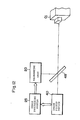
- Fig. 12 shows an example of application in which the optical axis of the illumination light which is projected from the illuminating unit 20 to an object O j coincides with the optical axis of the image pickup deive 40 to pick up the image of the object O j .
- the projecting direction of the illumination light and the image pickup direction are the same in the example of application to emphasize the contrast between the object and the background cescribed in conjunction with Figs. 6 to 8.
- the position of the special region must be accurately detected.
- the optical axis of the apparatus to pick up the object image coincident with the optical axis of the illuminating unit to project the spot light
- the coordinates of the special region on the image picked up can be directly used by the illuminating unit as the data indicative of the illuminating position of the spot light, so that this method is fairly convenient.
- a half mirror 48 is arranged on the optical axis connecting the image pickup device 40 and object O j at an angle of 45° with respect to the optical axis.
- the optical axis of the illuminating unit 20 is perpendicular to the optical axis connecting the image pickup device 40 and object O j and at the same time, the illuminating unit 20 is disposed at an angle of 45° with respect to the half mirror 48. Therefore, the optical axis of the illumination light irradiated from the illuminating unit 20 and deflected by the half mirror 48 coinciaes with the optical axis of the image pickup device 40.
- the illumination light generated from the illuminating unit 20 is reflected by the half mirror 48 so that its progressing direction is deflected by 90° and then irradiated to the object O j .
- the reflected light from the obj'ect O j passes through the half mirror 48 and enters the image pickup device 40, so that the image of the object O j is picked up.
- the image of the object O j is picked up by the image pickup device 40.
- the video signal indicative of the object O. is sent to the image processing system 25, so that the coordinates of the special region to which the spot light is irradiated are derived by the system 25.
- the spot-like image pattern is produced at the memory location corresponding to the coordinates of the special region in the image memory.
- Each of the systems shown in Figs. 1 and 6 intends to perform the color illumination and is provided with the video projectors 31, 32, and 33 to respectively project the lights of three primary colors, namely, red(R), green(G), and blue(E).
- These three video projectors are arranged at different positions in the space, so that there is the problem such that the color deviation occurs in the illumination area or on the surface of the object. For instance, the color deviation occurs near the boundary of the spot light or slit light. Consequently, the region where the color deviation occurred doesn't correspond to the illuminated region nor the non-illuminated region, resulting in deterioration in resolution of the illumination.
- the ratio of angles of the incident lights of three primary colors differs in dependence on each position in the illumination area, so that the color tones of the illumination lights in the illumination area become uneven. This causes the object to be erroneously recognized.
- Fig. 13 shows a system intending to make coincident the optical axes of the illumination lights which are projected from a plurality of video projectors disposed at different positions.
- Two half mirrors 51 and 52 are arranged at a proper distance on the optical axis of, e. g ., the video projector 31 of red so as to have an angle of almost 45° with respect to this optical axis, respectively.
- the other two video projectors 32 and 33 are arranged in a manner such that the green and blue lights which are projected therefrom are directed toward the half mirrors 51 and 52 and at the same time these lights can cross the optical axis of the projector 31 at an angle of nearly 90°, respectively.
- the ratio of the output light intensities of three video projectors 31 to 33 is determined in consideration of the transmission factors and reflection factors of the half mirrors 51 and 52 and may be set such that the ratio of the light intensities of three primary colors on the right side of the half mirror 52 in Fig. 13 becomes a predetermined value. It is apparent that a focusing optical system may be also arranged on the right side of the half mirror 52.
- the number of video projectors in which the optical axes of their output lights are made coincident with each other can be set to an arbitrary value.
- (n-1) half mirrors are used.
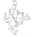
- F ig. 14 shows another example of a system to make coincident the optical axes of a plurality of illumination lights.
- Three prisms 61, 62, and 63 are used as means for deflecting the lights.
- the optical axis of the video projector 32 which projects the green illumination light is used as the reference axis.
- the optical axis of the projector 32 coincides with an optical axis W of the synthesized light.
- the green illumination light from the video projector 32 passes through two surfaces 62a and 62b of the prism 62 and further passes through surfaces 61a and 61b of the prism 61 and through surfaces 63a and 63b of the prism 63 and enters a focusing lens 64. Since the angle between the normal line of the surface 61a of the prism 61 and the green light is relatively small, no total reflection occurs on this surface. The same shall apply to the cases of the surface 62b of the prism 62 and the surface 63a of the prism 63.
- the red illumination light projected from the video projector 31 is totally reflected by the surface 61a of. the prism 61 and progresses toward the surface 61b.
- An interference film adapted to reflect the red light having the special angle of incidence has been formed on the surface 61b, so that the red light is reflected by the surface 6lb and progresses along the same axis as the optical axis W of the synthesized light.
- the blue light projected from the video projector 33 is totally reflected by the surface 63a of the prism 63 and progresses toward the surface 63b. Since an interference film adapted to reflect the blue light having the special angle of incidnece has been formed on the surface 63b, the blue light is reflected by the surface 63b and progresses along the same axis as the optical axis W of the synthesized light.
- the lights of three primary colors whose optical axes were made coincident are converged by the lens 64 and irradiated into the illumination area or to the object.
- F ig. 15 shows an example of a system which time-sharingly irradiates the illumination lights of three primary colors to the object and also time-sharingly picks up the image of the object for every color.
- This system is constituted such that a rotary plate 70 which is rotated by a drive motor 74 is disposed in front of the light projecting surface of the monochromatic video projector 30.
- the rotary plate 70 is composed of a red filter 71, a green filter 72, and a blue filter 73 which are arranged at regular angles.
- the image generated from the video projector 30 passes through the filter, the color image of the color corresponding to this filter is produced and projected.
- the video signals of the monochromatic images regarding three primary colors (red, green, blue) are supplied to the video projector 30.
- the monochromatic video projector 30 and the drive motor 74 are synchronized with each other in a manner such that each time the filters 71 to 73 of red, green and blue are sequentially located in front of the video projector 30, the monochromatic image of the color corresponding to the filter is projected.
- the rotating speed of the drive motor 74 is set to about ten rotations per second.
- the color TV camera 40 picks up the image of the object O j three times every time the drive motor 74 once rotates, obtains respective images of three primary colors, synthesizes these three images by an image synthesizer 49, and thereby deriving one color image.
- the monochromatic images of three primary colors are projected onto the object O j through the filters 71 to 73 by the monochromatic video projector 30 in synchronism with the rotation cf the rotary plate 70.
- the coaxial illumination of the color images of three primary colors can be realized and it is possible to perform the image processes in which no color deviation occurs and the resolution doesn't deteriorate.
Abstract
Description
- The present invention relates to an illumination system of the digital control type for use in, e.g., a visual system of an industrial robot or the like.
- Hitherto, visual systems for use in industrial robots use various kinds of methods such as indirect illuminations slit light projection, spot light projection, lattice pattern projection, and the like for the purposes of improvement of contrast between an object to be illuminated and the background, emphasis of edges of the object, detection of irregularity of the surface of object, and the like. However, according to those methods, each time the observation circumstances change, the intensity, positions direction, and pattern of the illumination, and the like must be manually or mechanically adjusted. Thus, there are the problems such that it takes a long time to adjust them and the reproducibility of the optimum illuminating conditions is very bad. Further, in the case of scanning a slit light or spot light, the mechanical movable parts such as a rotary mirror and the like are inevitable, so that there are the problems such that not only the scanning speed is limited but also the vibrations of the movable parts adversely influence on the scanning, and the like.
- It is an object of the present invention to provide an illumination system of the digital control type which can execute the scanning of the illumination pattern, and change, adjustments storage, and the like of the illumination pattern by way of the software, thereby fully eliminating the problems of the scanning speed, vibration, adjustment and the reproducibility of the illumination pattern, and the like of the conventional technology.
- According to the present invention, an illumination system of the digital control type comprises: an image memory for storing the data regarding a predetermined illumination pattern; video signal producing means for reading out the data from the image memory and converting them into a video signal representative of the illumination pattern; and light irradiating means for irradiating the light of the illumination pattern represented by the video signal to an object to be illuminated.
- When the color illumination is performed, the data regarding the illumination pattern of each color component of the color illumination light is stored into the image memory, respectively, for every color components, e.g., three primary colors. The video signal is produced for each clor component. The illumination pattern light of each color component is projected from the light irradiating means. The lights of the color components projected are synthesized and irradiated onto the object.
- According to the present invention, an arbitrary illumination pattern can be formed in the image memory and the illumination pattern formed can be also moved in the image memory under control of a computer. Therefore, the illumination pattern can be scanned without using any mechanical movable part aria the foregoing various problems which are caused due to the presence of the movable parts can be solved. Various kinds of specifications of the illumination light, such as the shape, size, brightness, etc. of the illumination pattern which are required by the industrial visual system can be easily set and controlled by the softwares. Also, the illumination pattern can be stored or reproduced at a high speed with a high degree of fidelity.
-
- Fig. 1 is a block diagram showing the outline of an electrical arrangement of an illumination system of the digital control type according to the present invention;
- Figs. 2A and 2B show the relation between the image pattern for illumination in an image memory and the illumination pattern in the illumination area formed using the image pattern;
- Figs. 3, 4, and 5 show other examples of the image in the image memory;
- Figs. 6 to 8 show an example of application of the present invention suitable to emphasize the contrast between the object and the background, in which Fig. 6 is a block diagram, Figs. 7A-to 7C are graphs showing the histograms, and
- Figs. 8A and 8B are color vector diagrams;
- Fig. 9 is a schematic constitutional diagram showing an example of application of the present invention adapted to scan a slit-like projection light;
- Fig. 10 is a block diagram showing an example of a constitution in which a video projector is synchronized with an image pickup device;
- Fig. 11 is a block diagram showing another example similar to the constitution shown in Fig. 10;
- Fig. 12 is a constitutional diagram showing an example in which the optical axis of the illumination light from an illumination unit coincides with the optical axis of an image pickup device;
- Fig. 13 is a diagram showing an arrangement of a system adapted to make the optical axes of the lights projected from three video projectors coincident with each other;
- Fig. 14 is a diagram showing another example of a system suitable to make the optical axes of a plurality of projected lights coincident with each other; and
- Figs. 15 and 16 show a system which performs the color illumination and color image pickup in a time-sharing manner, in which Fig. 15 show a whole arrangement and Fig. 16 is a front view of a rotary plate.
- Fig. 1 shows an outline of an electrical arrangement of an illumination system of the digital control type.
- This illumination system is controlled by a computer system 4 comprising: a central processing unit (CPU) 1; a
program memory 2 in which programs necessary to control the illumination are stored; and adata memory 3. An interface 5, which is connected to other external apparatus such as, e.g., a control system of a robot or the like, and an auxiliary memory 6 are also connected to the computer system 4 through a bus including an address bus, a control bus, and a data bus. - The illumination system can perform the color illumination and is provided with
image memories CPU 1 through the bus. TheCPU 1 can directly access the image memories 11 to 13 and control the writing or storing of image patterns (illumination patterns) into the image memories, production and movement of the illumination patterns in the image memories, and readout of the data indicative of the illumination patterns from the image memories. Consequently, the production of an arbitrary illumination pattern, setting of the size, brightness, position, and the like of this pattern, and scanning thereof can be freely executed in accordance with programs (softwares) cf the CUP 1. - The data regarding the illumination patterns read out from the image memories 11 to 13 are sent to video
signal producing circuits - The video signals indicative of the red, green, and blue illumination patterns produced are sent to
video projectors video projectors 31 to 33 toward an object to be illuminated. A video projector receives the video signal and outputs the image projection light representative of this video signal. In the case of the color video projector, it is constituted by three high luminance tubes (Cathode Ray Tubes), three sets of lenses disposed in front of those tubes, and a video signal processor to control the high liminance tubes. Fig. 1 conveniently shows the arrangement on the assumption that the video projector is provided for each color component of three primary colors. The lights generated from thevideo projectors 31 to 33 are synthesized in the space between the projectors and the object to be illuminated, so that the object is illuminated by the synthesized color illumination pattern. - Figs. 2A and 2B show the relation between the illumination pattern (image pattern) in the image memory (Fig. 2A) and the illumination pattern projected using the data of the image pattern in the illumination area (Fig. 2B). In the case where an image M1 to cause the spot-like illumination pattern to be generated is stored in the image memory, a spot illumination light ml is projected into the illumination area in correspondence to the image M1. When the image M1 is moved in the direction indicated by an arrow A in the image memory due to the control of the CPU l, the spot light m1 in the illumination area is also moved in the direction indicated by an arrow a. The movement of the image M1 in the image memory is realized by, for example, erasing the data at the original position and then writing the data of the image M1 at a new position. It will be obviously understood that when the image M1 in the image memory is moved in the direction indicated by an arrow B different from the arrow A, on the other hand, the spot light m1 in the illumination area is also moved in the direction indicated by an arrow b in correspondence to the arrow B.
- Fig. 3 shows an image M2 for another illumination pattern stored in the image memory. It will be easily appreciated that the slit-like illumination light is irradiated into the illumination area due to the image M2 and when the image M2 is moved in the direction indicated by an arrow in the image memory, the slit-like illumination pattern in the illumination area is also moved in the direction corresponding to this arrow.
- Further, if a lattice image pattern M3 as shown in Fig. 4 is produced in the image memory, a similar lattice illumination pattern is also formed in the illumination area. On the other hand, if an image pattern M4 of a figure as shown in Fig. 5 is formed in the image memory, an illumination pattern of a similar figure is also formed in the illumination area. The enlargements reduction, rotation, parallel movement, and the like of various kinds of patterns can be freely executed due to the softwares. The data indicative of the image patterns can be stored as files into the auxiliary memory 6 in Fig. 1 and read out and reproduced therefrom at any time.
- Figs. 6 to 8 show an example of application of the illumination system of the digital control type described above. This example is suitable to perform the illumination having the emphasized contrast between the object and the background.
- In Fig. 6, the same parts and components at those shown in Fig. 1 are designated by the same reference numerals. An
illuminating unit 20 has a constitution similar to the illumination system shown in Fig. 1 exclusing that the computer system 4 was removed therefrom. The video signal producing circuits are not shown in Fig. 6 for simplicity of the drawing. - In the initial step, the illumination data such that the lights projected from the
video projectors 31 to33 are synthesized to produce white light Iw is stored in the image memories 11 to 13. All of the pixel data in the respective image memories are equally set so as to project the uniform lights. - The lights reflected frcm the surface of the object illuminated by the white light are picked up by a
color television camera 40. The video signal is produced by thecamera 40 and separated into three video signals corresponding three primary colors. The data indicative of the video signals of the respective colors is stored intoimage memories - An
image processing system 25 includes a CUP, a program memory, a data memory, and the like and executes the following analyzing processes of the image data of the object stored in theimage memories 41 to 43. Then, theimage processing system 25 sets new data into the image memories 11 to 13. - The
image processing system 25 first produces histograms HR, HG, and HB regarding the brightnesses of the image data of red, green, and blue as three primary colors of the object which has been stored in theimage memories 41 to 43. Figs. 7A to 7C show examples of the histograms of the brightnesses of the object with respect to three primary colors. In each graph, an axis of abscissa denotes an intensity (brightness) and an axis of ordinate represents a frequency (number of pixels having same brightness). In the next step, the intensities bR, bG, and bB each having the maximum frequency (peak value) are obtained from these histograms. The representative vectors (rR y rG, r B) indicative of the colors of the object are calculated using the values, of intensities bR, bG, and bB by the following expressions.


- The data indicative of the values IR= rR.I, IG = rG.I, and IB= rB.I (I is a constant) proportional to the resultant representative vectors rR, rG, and rB are set into the
image memories unit 20, respectively. In each image memory, the data of the same value is set with regard to all pixels. - The lights are projected to the object from the
video projectors 31 to 33 on the basis of the data newly set into the image memories 11 to 13. The color of the synthesized light IN of the projected lights from theprojectors 31 to 33 is substantially the same as that of the surface of the object. Namely, since the light having almost the same color as that of the surface of the object is projected, the contrast between the object and the background is enhanced. - The principle of the emphasis of the contrast will then be described with reference to Figs. 8A and 8B. Fig. 8A shows a vector diagram when the white light IW was projected. Fig. 8B shows a vector diagram when the light IN having almost the same color as that of the surface of the object was projected. In the diagrams, reference characters A and B denote vectors indicative of the colors of the object and backgrounds respectively. It can be seen from Fig. 8A that there is the small difference between the intensity RA1 of reflected lights from the object and the intensity RB1 of reflected lights from the background when the white light IW was projected. On the other hand, as shown in Fig. 8B, there is the large difference between the reflected light intensity RA2 from the object and the reflected light intensity Rn2 from the background when the light IN having substantially the same color as that of the surface of the object was projected. Thus, it will be understood that the contrast between the object and the background is emphasized in Fig. 8B.
- Fig. 9 shows another example of application of an illumination system according to the present invention.
- The system shown in this diagram is constituted as follows. The slit-like image pattern M2 in the image memory (e.g., 11) is moved in the direction indicated by an arrow D in the diagram. This image pattern is converted to the video signal and supplied to a
CRT display device 26. The slit-like illumination pattern m2 is formed in an illumination area L by theCRT 26 through alens 27. This illumination pattern is moved in the direction indicated by an arrow d in the diagram. The scanning of the slit-like illumination pattern is frequently requested in the three-dimensional object sensing or recognizing system. According to the present invention, the scanner without having any movable part can be realized and the width. and direction of the illumination pattern m2 can be freely changed due to the softwares. - Returning to the system shown in Fig. 6, the illuminating
unit 20 has thevideo projectors 31 to 33 and the illumination lights are projected frcm these video projectors to the object. Each video projector uses an electron beam which is vertically and horizontally scanned in order to output an image in a manner similar to the television system. Therefore, even if an illumination pattern such as to uniformly illuminate the illumination area was given, the illumination pattern includes both the bright and dark portions in the illumination area when it is momentarily observed. On the other hand, theTV camera 40 also converts the two-dimensional image to the serial video signal due to the vertical and horizontal scans. - Consequently, unless the light projection timing and the image pickup timing are synchronized, the problem such that a fringe extending in the lateral direction appears in the image picked up is caused. In addition, if there is a slight deviation between the synchronizing frequency of the video projector and that of the
TV camera 40, the above-mentioned fringe moves in the vertical direction on the CRT screen. - Fig. 10 shows an example of an arrangement to solve such a problem. A video projector is indicated at numeral 30 in this diagram. The
video projector 30 may be used for either the color illumination or the monochromatic illumination. - The illumination video signal read out from the image memory and converted to the video signal is supplied to the
video projector 30. A synchronizing signal is also supplied to thevideo projector 30 from a syncsignal separating circuit 45, thereby allowing the video signal to be synchronized with this sync signal. - On the other hand, the video signal outputted from the
image pickup device 40 is sent to adistribution amplifier 44, by which it is divided into two video signals. One of them is supplied to an image processing apparatus (e.g.,system 25 in Fig. 6) and the other is supplied to the syncsignal separating circuit 45, respectively. The separatingcircuit 45 separates the sync signal from the image video signal received and sends it to thevideo projector 30 as mentioned above. - As described above, the scanning timing by the
video projector 30 serving as the illuminating means is completely synchronized with the scanning timing by theimage pickup device 40, so that the occurrence of fringe in the image picked up is prevented and the clear image can be always obtained. Therefore, the image process can be performed in the image processing system as well with a high degree of precision. - The sync signal may be also separated from the illumination video signal which is given to the
video projector 30 and then supplied to theimage pickup device 40. - As shown in Fig. 11, in addition, a sync signal which is generated from a
sync signal generator 46, which is separately provided, may be also distributed to thevideo projector 30 andimage pickup device 40 by adistribution amplifier 47. - Fig. 12 shows an example of application in which the optical axis of the illumination light which is projected from the illuminating
unit 20 to an object Oj coincides with the optical axis of the image pickup deive 40 to pick up the image of the object Oj. - It is obviously desirable that the projecting direction of the illumination light and the image pickup direction are the same in the example of application to emphasize the contrast between the object and the background cescribed in conjunction with Figs. 6 to 8. In the case of selectively locally illuminating only the special region of the object, e.g., the most characteristic portion, the position of the special region must be accurately detected. In such a case, by making the optical axis of the apparatus to pick up the object image coincident with the optical axis of the illuminating unit to project the spot light, the coordinates of the special region on the image picked up can be directly used by the illuminating unit as the data indicative of the illuminating position of the spot light, so that this method is fairly convenient.
- Referring again to Fig. 12, a
half mirror 48 is arranged on the optical axis connecting theimage pickup device 40 and object Oj at an angle of 45° with respect to the optical axis. The optical axis of the illuminatingunit 20 is perpendicular to the optical axis connecting theimage pickup device 40 and object Oj and at the same time, the illuminatingunit 20 is disposed at an angle of 45° with respect to thehalf mirror 48. Therefore, the optical axis of the illumination light irradiated from the illuminatingunit 20 and deflected by thehalf mirror 48 coinciaes with the optical axis of theimage pickup device 40. - In the arrangement of Fig. 12, the illumination light generated from the illuminating
unit 20 is reflected by thehalf mirror 48 so that its progressing direction is deflected by 90° and then irradiated to the object Oj. The reflected light from the obj'ect Oj passes through thehalf mirror 48 and enters theimage pickup device 40, so that the image of the object Oj is picked up. - In the case of irradiating the spot light to only the special region of the object Oj, the following processes are performed.
- First, the image of the object Oj is picked up by the
image pickup device 40. The video signal indicative of the object O. is sent to theimage processing system 25, so that the coordinates of the special region to which the spot light is irradiated are derived by thesystem 25. The spot-like image pattern is produced at the memory location corresponding to the coordinates of the special region in the image memory. By supplying the video signal indicative of the data in the image memory to the video projector, the spot light can be irradiated to the special region of the object Oj. - Each of the systems shown in Figs. 1 and 6 intends to perform the color illumination and is provided with the
video projectors - Fig. 13 shows a system intending to make coincident the optical axes of the illumination lights which are projected from a plurality of video projectors disposed at different positions. Two half mirrors 51 and 52 are arranged at a proper distance on the optical axis of, e.g., the
video projector 31 of red so as to have an angle of almost 45° with respect to this optical axis, respectively. The other twovideo projectors projector 31 at an angle of nearly 90°, respectively. - With this arrangement, the optical axes of the red light transmitted through the half mirrors 51 and 52, green light reflected by the
half mirror 51 and transmitted through thehalf mirror 52, and blue light reflected by the half mirror 52 completely coincide with each other. Consequently, it is possible to realize the coaxial illumination as if the lights of three primary colors were irradiated from a single light source. The problems such as the color deviation and unevenness of the color tones depending on the locations mentioned above are solved. - The ratio of the output light intensities of three
video projectors 31 to 33 is determined in consideration of the transmission factors and reflection factors of the half mirrors 51 and 52 and may be set such that the ratio of the light intensities of three primary colors on the right side of thehalf mirror 52 in Fig. 13 becomes a predetermined value. It is apparent that a focusing optical system may be also arranged on the right side of thehalf mirror 52. - The number of video projectors in which the optical axes of their output lights are made coincident with each other can be set to an arbitrary value. To make the optical axes of the output lights on n video projectors coincident, (n-1) half mirrors are used.
- Fig. 14 shows another example of a system to make coincident the optical axes of a plurality of illumination lights. Three
prisms - The optical axis of the
video projector 32 which projects the green illumination light is used as the reference axis. In other words, the optical axis of theprojector 32 coincides with an optical axis W of the synthesized light. The green illumination light from thevideo projector 32 passes through twosurfaces 62a and 62b of theprism 62 and further passes through surfaces 61a and 61b of theprism 61 and throughsurfaces 63a and 63b of theprism 63 and enters a focusinglens 64. Since the angle between the normal line of the surface 61a of theprism 61 and the green light is relatively small, no total reflection occurs on this surface. The same shall apply to the cases of thesurface 62b of theprism 62 and the surface 63a of theprism 63. - The red illumination light projected from the
video projector 31 is totally reflected by the surface 61a of. theprism 61 and progresses toward the surface 61b. An interference film adapted to reflect the red light having the special angle of incidence has been formed on the surface 61b, so that the red light is reflected by the surface 6lb and progresses along the same axis as the optical axis W of the synthesized light. - The blue light projected from the
video projector 33 is totally reflected by the surface 63a of theprism 63 and progresses toward thesurface 63b. Since an interference film adapted to reflect the blue light having the special angle of incidnece has been formed on thesurface 63b, the blue light is reflected by thesurface 63b and progresses along the same axis as the optical axis W of the synthesized light. - In this manner, the lights of three primary colors whose optical axes were made coincident are converged by the
lens 64 and irradiated into the illumination area or to the object. - Fig. 15 shows an example of a system which time-sharingly irradiates the illumination lights of three primary colors to the object and also time-sharingly picks up the image of the object for every color.
- This system is constituted such that a
rotary plate 70 which is rotated by adrive motor 74 is disposed in front of the light projecting surface of themonochromatic video projector 30. As shown in Fig. 16, therotary plate 70 is composed of ared filter 71, agreen filter 72, and ablue filter 73 which are arranged at regular angles. When the image generated from thevideo projector 30 passes through the filter, the color image of the color corresponding to this filter is produced and projected. The video signals of the monochromatic images regarding three primary colors (red, green, blue) are supplied to thevideo projector 30. Themonochromatic video projector 30 and thedrive motor 74 are synchronized with each other in a manner such that each time thefilters 71 to 73 of red, green and blue are sequentially located in front of thevideo projector 30, the monochromatic image of the color corresponding to the filter is projected. For example, the rotating speed of thedrive motor 74 is set to about ten rotations per second. - The
color TV camera 40 picks up the image of the object Oj three times every time thedrive motor 74 once rotates, obtains respective images of three primary colors, synthesizes these three images by animage synthesizer 49, and thereby deriving one color image. - The monochromatic images of three primary colors are projected onto the object Oj through the
filters 71 to 73 by themonochromatic video projector 30 in synchronism with the rotation cf therotary plate 70. Thus, the coaxial illumination of the color images of three primary colors can be realized and it is possible to perform the image processes in which no color deviation occurs and the resolution doesn't deteriorate.
Claims (10)
Priority Applications (1)
| Application Number | Priority Date | Filing Date | Title |
|---|---|---|---|
| AT86104289T ATE84627T1 (en) | 1985-03-30 | 1986-03-27 | DIGITAL CONTROL TYPE LIGHTING SYSTEM. |
Applications Claiming Priority (6)
| Application Number | Priority Date | Filing Date | Title |
|---|---|---|---|
| JP67996/85 | 1985-03-30 | ||
| JP60067996A JPH07122818B2 (en) | 1985-03-30 | 1985-03-30 | Lighting device for visual recognition |
| JP99852/85U | 1985-06-28 | ||
| JP9985285U JPS629860U (en) | 1985-06-28 | 1985-06-28 | |
| JP153770/85 | 1985-07-11 | ||
| JP60153770A JP2548695B2 (en) | 1985-07-11 | 1985-07-11 | Digital lighting |
Publications (3)
| Publication Number | Publication Date |
|---|---|
| EP0207229A2 true EP0207229A2 (en) | 1987-01-07 |
| EP0207229A3 EP0207229A3 (en) | 1989-04-05 |
| EP0207229B1 EP0207229B1 (en) | 1993-01-13 |
Family
ID=27299616
Family Applications (1)
| Application Number | Title | Priority Date | Filing Date |
|---|---|---|---|
| EP86104289A Expired - Lifetime EP0207229B1 (en) | 1985-03-30 | 1986-03-27 | Illumination system of the digital control type |
Country Status (4)
| Country | Link |
|---|---|
| US (1) | US4703344A (en) |
| EP (1) | EP0207229B1 (en) |
| AT (1) | ATE84627T1 (en) |
| DE (1) | DE3687483T2 (en) |
Families Citing this family (16)
| Publication number | Priority date | Publication date | Assignee | Title |
|---|---|---|---|---|
| JPS6491083A (en) * | 1987-10-02 | 1989-04-10 | Mitsubishi Electric Corp | Congestion level detector for elevator hall |
| US4979135A (en) * | 1988-01-27 | 1990-12-18 | Storage Technology Corporation | Vision system illumination calibration apparatus |
| US4975770A (en) * | 1989-07-31 | 1990-12-04 | Troxell James D | Method for the enhancement of contours for video broadcasts |
| JP3409330B2 (en) * | 1991-02-08 | 2003-05-26 | ソニー株式会社 | Adjustment device and adjustment method for projection display device |
| DE69231597T2 (en) * | 1991-03-19 | 2001-05-31 | Hitachi Ltd | Liquid crystal display device |
| US7187141B2 (en) * | 1997-08-26 | 2007-03-06 | Color Kinetics Incorporated | Methods and apparatus for illumination of liquids |
| US7482764B2 (en) | 1997-08-26 | 2009-01-27 | Philips Solid-State Lighting Solutions, Inc. | Light sources for illumination of liquids |
| US7128266B2 (en) | 2003-11-13 | 2006-10-31 | Metrologic Instruments. Inc. | Hand-supportable digital imaging-based bar code symbol reader supporting narrow-area and wide-area modes of illumination and image capture |
| US7490774B2 (en) | 2003-11-13 | 2009-02-17 | Metrologic Instruments, Inc. | Hand-supportable imaging based bar code symbol reader employing automatic light exposure measurement and illumination control subsystem integrated therein |
| US7594609B2 (en) | 2003-11-13 | 2009-09-29 | Metrologic Instruments, Inc. | Automatic digital video image capture and processing system supporting image-processing based code symbol reading during a pass-through mode of system operation at a retail point of sale (POS) station |
| US7464877B2 (en) | 2003-11-13 | 2008-12-16 | Metrologic Instruments, Inc. | Digital imaging-based bar code symbol reading system employing image cropping pattern generator and automatic cropped image processor |
| FR2837012B1 (en) * | 2002-03-11 | 2005-02-11 | Vision Control Applic Sa | DEVICE AND METHOD FOR IDENTIFICATION AND VERIFICATION OF MARKING |
| US7841533B2 (en) | 2003-11-13 | 2010-11-30 | Metrologic Instruments, Inc. | Method of capturing and processing digital images of an object within the field of view (FOV) of a hand-supportable digitial image capture and processing system |
| US7395897B2 (en) * | 2004-04-09 | 2008-07-08 | Vecta Oil & Gas, Ltd. | Accelerated weight drop configurable for use as a shear wave seismic energy source and a method of operation thereof |
| EP2826237A4 (en) * | 2012-03-13 | 2015-08-19 | Dolby Lab Licensing Corp | Lighting system and method for image and object enhancement |
| US20140267713A1 (en) * | 2013-03-15 | 2014-09-18 | Cryoxtract Instruments, Llc | Machine Vision System for Frozen Aliquotter for Biological Samples |
Citations (1)
| Publication number | Priority date | Publication date | Assignee | Title |
|---|---|---|---|---|
| US4368963A (en) * | 1978-06-29 | 1983-01-18 | Michael Stolov | Multicolor image or picture projecting system using electronically controlled slides |
Family Cites Families (5)
| Publication number | Priority date | Publication date | Assignee | Title |
|---|---|---|---|---|
| US4481531A (en) * | 1977-11-03 | 1984-11-06 | Massachusetts Institute Of Technology | Microchannel spatial light modulator |
| US4488173A (en) * | 1981-08-19 | 1984-12-11 | Robotic Vision Systems, Inc. | Method of sensing the position and orientation of elements in space |
| JPS5974781A (en) * | 1982-10-21 | 1984-04-27 | Toshiba Corp | Method and device for measurement of convergence of color picture tube |
| US4611241A (en) * | 1983-10-12 | 1986-09-09 | Zenith Electronics Corporation | Projection television set up method and apparatus |
| US4602272A (en) * | 1984-11-13 | 1986-07-22 | Rca Corporation | Electron beam intensity profile measuring system and method |
-
1986
- 1986-03-24 US US06/843,390 patent/US4703344A/en not_active Expired - Lifetime
- 1986-03-27 EP EP86104289A patent/EP0207229B1/en not_active Expired - Lifetime
- 1986-03-27 DE DE8686104289T patent/DE3687483T2/en not_active Expired - Fee Related
- 1986-03-27 AT AT86104289T patent/ATE84627T1/en not_active IP Right Cessation
Patent Citations (1)
| Publication number | Priority date | Publication date | Assignee | Title |
|---|---|---|---|---|
| US4368963A (en) * | 1978-06-29 | 1983-01-18 | Michael Stolov | Multicolor image or picture projecting system using electronically controlled slides |
Non-Patent Citations (2)
| Title |
|---|
| COMPUTER DESIGN, vol. 13, no. 7, July 1974, pages 14-16; "Image digitizer accepts real-time input, operates on- or offline" * |
| COMPUTER, vol. 15, no. 12, December 1983, pages 17-32, IEEE, Long Beach, California, US; R.C. GONZALEZ et al.: "Computer vision techniques for industrial applications and robot control" * |
Also Published As
| Publication number | Publication date |
|---|---|
| EP0207229B1 (en) | 1993-01-13 |
| ATE84627T1 (en) | 1993-01-15 |
| DE3687483D1 (en) | 1993-02-25 |
| US4703344A (en) | 1987-10-27 |
| DE3687483T2 (en) | 1993-08-12 |
| EP0207229A3 (en) | 1989-04-05 |
Similar Documents
| Publication | Publication Date | Title |
|---|---|---|
| US4703344A (en) | Illumination system of the digital control type | |
| US5631976A (en) | Object imaging system | |
| US6118484A (en) | Imaging apparatus | |
| US4660094A (en) | Method for focus adjustment of a picture scanning and recording system | |
| US3835245A (en) | Information modification in image analysis systems employing line scanning | |
| US6018361A (en) | Apparatus for and method of measuring image qualities of color display unit | |
| US5051834A (en) | Projection-type display apparatus utilizing both zero-order and first-order diffracted beams | |
| US4591918A (en) | Image sensor system | |
| JP2893078B2 (en) | Shading correction method and device | |
| JPS598086A (en) | Form detector | |
| JP5540664B2 (en) | Optical axis adjustment system, optical axis adjustment device, optical axis adjustment method, and program | |
| JPH071164B2 (en) | 3D shape recognition device | |
| US5949900A (en) | Fine pattern inspection device capable of carrying out inspection without pattern recognition | |
| US5091776A (en) | Apparatus and method for enhancing the quality of a video signal produced by electronic shearography | |
| KR100340012B1 (en) | Method of checking products and computer vision system using rotating mirror | |
| US4955680A (en) | Method and apparatus for automatically adjusting the focus of cathode ray tubes | |
| JPH0969973A (en) | Position adjusting method for solid-state image pickup element | |
| JP2805897B2 (en) | Image quality inspection equipment | |
| JPH0739940B2 (en) | Digital lighting equipment | |
| JP2000125289A (en) | Method for generating image with emphasized recessed part | |
| JP3534817B2 (en) | Automatic lighting setting method and device | |
| JP2004015297A (en) | Stereoscopic observation apparatus and method for generating stereoscopic image reproducing color of object surface | |
| JP3724659B2 (en) | Image processing device | |
| JPH1163954A (en) | Measuring device of three-dimensional shape | |
| JPH0399211A (en) | Recognition of body |
Legal Events
| Date | Code | Title | Description |
|---|---|---|---|
| PUAI | Public reference made under article 153(3) epc to a published international application that has entered the european phase |
Free format text: ORIGINAL CODE: 0009012 |
|
| 17P | Request for examination filed |
Effective date: 19860327 |
|
| AK | Designated contracting states |
Kind code of ref document: A2 Designated state(s): AT BE CH DE FR GB IT LI LU NL SE |
|
| PUAL | Search report despatched |
Free format text: ORIGINAL CODE: 0009013 |
|
| AK | Designated contracting states |
Kind code of ref document: A3 Designated state(s): AT BE CH DE FR GB IT LI LU NL SE |
|
| 17Q | First examination report despatched |
Effective date: 19901001 |
|
| GRAA | (expected) grant |
Free format text: ORIGINAL CODE: 0009210 |
|
| AK | Designated contracting states |
Kind code of ref document: B1 Designated state(s): AT BE CH DE FR GB IT LI LU NL SE |
|
| PG25 | Lapsed in a contracting state [announced via postgrant information from national office to epo] |
Ref country code: NL Effective date: 19930113 Ref country code: LI Effective date: 19930113 Ref country code: CH Effective date: 19930113 Ref country code: BE Effective date: 19930113 Ref country code: AT Effective date: 19930113 |
|
| REF | Corresponds to: |
Ref document number: 84627 Country of ref document: AT Date of ref document: 19930115 Kind code of ref document: T |
|
| ITF | It: translation for a ep patent filed |
Owner name: STUDIO TORTA SOCIETA' SEMPLICE |
|
| REF | Corresponds to: |
Ref document number: 3687483 Country of ref document: DE Date of ref document: 19930225 |
|
| ET | Fr: translation filed | ||
| PG25 | Lapsed in a contracting state [announced via postgrant information from national office to epo] |
Ref country code: LU Free format text: LAPSE BECAUSE OF NON-PAYMENT OF DUE FEES Effective date: 19930331 |
|
| REG | Reference to a national code |
Ref country code: CH Ref legal event code: PL |
|
| NLV1 | Nl: lapsed or annulled due to failure to fulfill the requirements of art. 29p and 29m of the patents act | ||
| PLBE | No opposition filed within time limit |
Free format text: ORIGINAL CODE: 0009261 |
|
| STAA | Information on the status of an ep patent application or granted ep patent |
Free format text: STATUS: NO OPPOSITION FILED WITHIN TIME LIMIT |
|
| 26N | No opposition filed | ||
| EAL | Se: european patent in force in sweden |
Ref document number: 86104289.3 |
|
| PGFP | Annual fee paid to national office [announced via postgrant information from national office to epo] |
Ref country code: SE Payment date: 19960322 Year of fee payment: 11 |
|
| PG25 | Lapsed in a contracting state [announced via postgrant information from national office to epo] |
Ref country code: SE Effective date: 19970328 |
|
| REG | Reference to a national code |
Ref country code: GB Ref legal event code: 746 Effective date: 19970516 |
|
| ITPR | It: changes in ownership of a european patent |
Owner name: OFFERTA DI LICENZA AL PUBBLICO;AL PUBBLICO |
|
| REG | Reference to a national code |
Ref country code: FR Ref legal event code: D6 |
|
| EUG | Se: european patent has lapsed |
Ref document number: 86104289.3 |
|
| PGFP | Annual fee paid to national office [announced via postgrant information from national office to epo] |
Ref country code: GB Payment date: 19980216 Year of fee payment: 13 |
|
| PGFP | Annual fee paid to national office [announced via postgrant information from national office to epo] |
Ref country code: FR Payment date: 19980320 Year of fee payment: 13 |
|
| PG25 | Lapsed in a contracting state [announced via postgrant information from national office to epo] |
Ref country code: GB Free format text: LAPSE BECAUSE OF NON-PAYMENT OF DUE FEES Effective date: 19990327 |
|
| GBPC | Gb: european patent ceased through non-payment of renewal fee |
Effective date: 19990327 |
|
| PG25 | Lapsed in a contracting state [announced via postgrant information from national office to epo] |
Ref country code: FR Free format text: LAPSE BECAUSE OF NON-PAYMENT OF DUE FEES Effective date: 19991130 |
|
| REG | Reference to a national code |
Ref country code: FR Ref legal event code: ST |
|
| PGFP | Annual fee paid to national office [announced via postgrant information from national office to epo] |
Ref country code: DE Payment date: 20020404 Year of fee payment: 17 |
|
| PG25 | Lapsed in a contracting state [announced via postgrant information from national office to epo] |
Ref country code: DE Free format text: LAPSE BECAUSE OF NON-PAYMENT OF DUE FEES Effective date: 20031001 |
|
| PG25 | Lapsed in a contracting state [announced via postgrant information from national office to epo] |
Ref country code: IT Free format text: LAPSE BECAUSE OF NON-PAYMENT OF DUE FEES;WARNING: LAPSES OF ITALIAN PATENTS WITH EFFECTIVE DATE BEFORE 2007 MAY HAVE OCCURRED AT ANY TIME BEFORE 2007. THE CORRECT EFFECTIVE DATE MAY BE DIFFERENT FROM THE ONE RECORDED. Effective date: 20050327 |