EP0184262A1 - Steerable aerostatic balloon - Google Patents
Steerable aerostatic balloon Download PDFInfo
- Publication number
- EP0184262A1 EP0184262A1 EP85201975A EP85201975A EP0184262A1 EP 0184262 A1 EP0184262 A1 EP 0184262A1 EP 85201975 A EP85201975 A EP 85201975A EP 85201975 A EP85201975 A EP 85201975A EP 0184262 A1 EP0184262 A1 EP 0184262A1
- Authority
- EP
- European Patent Office
- Prior art keywords
- envelope
- balloon
- internal
- network
- external
- Prior art date
- Legal status (The legal status is an assumption and is not a legal conclusion. Google has not performed a legal analysis and makes no representation as to the accuracy of the status listed.)
- Granted
Links
Images


Classifications
-
- B—PERFORMING OPERATIONS; TRANSPORTING
- B64—AIRCRAFT; AVIATION; COSMONAUTICS
- B64B—LIGHTER-THAN AIR AIRCRAFT
- B64B1/00—Lighter-than-air aircraft
- B64B1/58—Arrangements or construction of gas-bags; Filling arrangements
- B64B1/60—Gas-bags surrounded by separate containers of inert gas
Definitions
- the invention relates to a controllable aerostatic balloon and can in particular be applied for the production of balloons of large volumes which can be free (airships, space balloons ...) or captive (balloons playing the role of cranes for loading and unloading materials).
- controllable space balloons intended to drive a charge for the exploration of the atmospheric layers; these balloons which are also at low overpressure when they are of large volumes, generally comprise a carrier balloon inflated with a gas lighter than air such as helium, and a stabilizing balloon inflated with air, linked to the first and located below it; piloting is carried out by varying the pressure of the stabilizing balloon at constant volume by admitting air into it or escaping air.
- these systems have faults which are linked to the fact that the piloting forces are only developed by the stabilized balloon. tor: level changes are slow to obtain and difficult to control at altitude, and these balloons are unstable at their ceiling altitude.
- the present invention proposes to overcome the above-mentioned defects of known controllable aerostatic balloons.
- An essential objective of the invention is to provide an aerostatic balloon whose volume can be very high (up to 10 6 m 3) in order to be able to transport large loads and whose gas retention structure is capable of bear very high overpressures (several hundred millibars).
- the invention thus aims to provide a balloon whose aerostatic piloting can be ensured by variation of gas masses.
- Another objective of the invention is to considerably increase the efficiency of piloting maneuvers (in the vertical direction) in order to allow rapid and well-controlled level changes, whatever the altitude.
- Another objective is to obtain good stability of the balloon whatever its altitude and in particular at the ceiling.
- Another objective of the invention is to facilitate balloon launching operations on the ground.
- the structure of such a balloon makes it capable of withstanding high overpressures: the tensions developed by the overpressure are in fact taken up in large proportion, either by the network of longitudinal reinforcements, or by the network of circumferential reinforcements or by the interpolar link. It is thus possible to provide thin envelopes of very low surface masses, while subjecting the balloon to overpressures of up to 500 or 600 millibars.
- the outer casing can in particular be made of a material with a thickness approximately between 100 and 300 microns, each inner casing can be made of an even thinner material, with a thickness approximately between 10 and 100 microns.
- the piloting forces are proportional to the total volume of the external envelope and benefit from a multiplier effect compared to conventional systems with two separate balloons.
- reaction forces applied to the balloon in the event of a change in altitude are proportional to the total volume of the external envelope and the balloon has improved stability which remains good at the ceiling altitude when the amount of air has become very small in the external envelope.
- each internal envelope may be associated with helium inflation means or with deflation means thereof.
- the balloon according to the invention may comprise a single internal envelope disposed in its external envelope. It can also include several internal envelopes arranged inside the external envelope according to the requirements of the envisaged application.
- the inflation and deflation means associated with the internal envelopes may, in this case, include means for transferring the gas from one internal envelope to another; they can also be adapted to give different pressures to the various internal envelopes.
- the balloon can also comprise several internal envelopes arranged side by side so as to inflate in contact with each other and / or in contact with the external envelope, the lower poles of said internal envelopes substantially coinciding with the lower pole of the external envelope. , however that their upper poles substantially coincide with the upper pole of said outer shell.
- the invention applies equally well in the space balloons sector, in particular stratospheric balloons, as in that of airships (balloons provided with horizontal and possibly vertical propulsion means) or in that of captive balloons (balloons linked to a cable and piloted by remote control for load transfer).
- the balloon according to the invention constitutes a basic module which can be associated with several other similar modules, either in vertical superposition, or in horizontal juxtaposition, or even by combining these arrangements, with a view to obtaining aerostatic assemblies of very large volumes (high capacity airships).
- controllable aerostatic balloon shown by way of example in FIGS. 1 to 6 constitutes the simplest basic module which can be used alone or in combination with other modules, to make a space balloon, an airship, or a captive load transfer balloon.
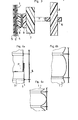
- This balloon comprises in the first place an external envelope 1 which is produced by assembling rectangular spindles, by any known means, along their rectilinear edges.
- This envelope thus comprises a cylindrical portion 1a which is extended by gathered pleated portions, the edges of which are attached to pole pieces 2 and 3 disposed at the poles, lower and upper of the envelope on the axis thereof.
- the material constituting the external envelope 1 is an airtight composite material, having in the example three layers as shown in FIG. 3: on the outside a heat-sealable polyester film 4, on the inside a weldable polyethylene film 5 and, between the two, a "kevlar-polyester” fabric 6.
- the assembly has a thickness of the order of 200 microns.
- the fabric 6 comprises a polyester weft arranged in the circumferential direction and a "kevlar" warp arranged in the longitudinal direction. It thus has an asymmetric resistance, higher in the longitudinal direction than in the circumferential direction; moreover, it is inextensible in the longitudinal direction (by "inextensible” means a material whose elastic elongation does not exceed 1 to 2% approximately), whereas, in the circumferential direction, the material has a greater elasticity ( about 10% elongation).
- the outer envelope 1 is surrounded by a network of circumferential reinforcements such as 7 and a network of longitudinal reinforcements such as 8.
- the circumferential reinforcements 7 are located in planes perpendicular to the axis of the envelope, distributed over the height of the latter.
- Each circumferential reinforcement 7 consists of a strip of material inextensible of high resistance, for example "Kevlar" of 5/10 mm thick by 20 to 50 mm wide; the two ends of each strip are assembled by gluing one on the other.
- each strip 7 is linked at a few points to the external envelope 1, so as to be able to play relative to the latter in order to transmit to it only weak forces compared to those supported by said strip.
- the fastenings of each strip 7 are produced by means of conjugated portions 8 and 9 of attachment materials of the "Velcro" type, which are glued opposite, on the one hand, to the external envelope 1, on the other hand on the band concerned 7.
- Each reinforcing strip 7 is thus fixed around and outside of the external envelope 1 and, for the inflated state of this envelope, comes into contact with the latter over its entire periphery without transmitting significant constraints to it.
- the longitudinal reinforcements 8 are located in meridian planes distributed around the outer envelope; they are positioned outside the network of circumferential reinforcements, by positioning means which hold them.
- these positioning means are constituted by flexible belts 10 (fabric or other) which are crossed by said longitudinal reinforcements.
- Each reinforcement 8 is made of an inextensible material of high resistance and can be constituted as before by strips of "kevlar".
- the longitudinal reinforcements 8 extend integrally between the lower and upper poles of the outer casing and are fixed at these poles on the pole pieces 2 and 3.
- the outer casing 1 has a length in the longitudinal direction greater than the length of each longitudinal reinforcement strip 8, so that, in the fully inflated state, the longitudinal forces are essentially supported by the network of longitudinal reinforcements 8.
- the outer casing 1 in the not fully inflated state, has peripheral pleats P located between the circumferential reinforcements.
- lobes appear between the circumferential reinforcements, and are all the more pronounced the greater the pressure in the envelope (FIGS. 4b and 4c).
- pole pieces 2 and 3 are joined by an inextensible interpolar link 11 extending along the axis of the outer casing 1; in the example, this link is constituted by a bundle of bands made of an inextensible material of high resistance, in particular "kevlar".
- the length of the interpolar link 11 is less than that of the spindles forming the external envelope and is adjusted as a function of the various parameters of the balloon to obtain the desired external shape (cf. patent FR n ° 2 472 971 already mentioned).
- the balloon comprises an internal envelope 12 which is located inside the external envelope 1; this envelope 12 is produced in a manner analogous to the external envelope by assembling rectangular spindles whose upper and lower edges are joined together and fixed on the pole pieces 2 and 3.
- the internal envelope 12 thus has a cylindrical portion 12a and the diameter of the latter is dimensioned to correspond to that of the cylindrical portion ′ of the external envelope inflated to the maximum, so that this portion 12a comes to bear against the inflation against said portion 1a.
- the internal envelope has to withstand only low stresses and it can be made of a very thin material with a thickness less than that of the external envelope, in particular of the order of 50 microns; this material can be a composite material of the type comprising a layer of "mylar” coated with an aluminum coating in order to make it helium-tight.
- the inner shell is inflated with helium (or other gas lighter than air), while the outer shell is inflated with air.
- Helium inflation can only be carried out on the ground when the balloon is launched, the upper pole piece being provided with a safety valve to allow an escape in the event of an internal overpressure greater than a limit.
- the balloon can also be fitted with on-board means of inflating and deflating the internal envelope, in order to increase flight safety (leakage compensation, ability to increase the efficiency of piloting in the event of danger).
- the balloon is fitted with on-board means for admitting air into the external envelope and means for discharging air; these means are used on the ground for inflating said envelope and, in flight, for piloting it (an air intake causing a descent of the balloon and an air evacuation causing a rise).
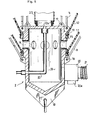
- FIG. 5 shows in axial section the lower pole piece 2 by means of which this air intake or exhaust takes place.
- This part forms an internal chamber 13 which communicates through lights 14 with the interior of the external envelope 1.
- the lower part of this external envelope is fixed in a sealed manner around said part below the lights. 14, however that the lower part of the internal envelope 12 is similarly fixed above said slots 14.
- Each envelope 1 or 12 is fixed around the part 2 by means of an annular bead 15 secured to the edge of the envelope and a clamp 16.
- the pole piece 2 externally comprises attachment means such as 17 of the bundle of bands forming the interpolar link 11 and attachment means such as 18 of the bands forming the network of longitudinal reinforcements 8; it also carries at its lower part a means 19 for hooking the load.
- the part 2 is equipped with a three-way valve 20, which allows either to carry out an air evacuation by an outlet 20a, or to admit compressed air coming from a turbo-compressor (or other equivalent means) through a duct 21.
- This turbo-compressor is on board and can be accommodated with the load.
- the internal envelope 12 is inflated with helium through a conduit 22 which passes tightly through the part 2 to open out in the upper part thereof through an orifice 22a located on the axis of the balloon.
- a porous sleeve 23 is provided inside thereof around the orifice 22a; this sleeve extends from one pole to the other: when the conduit 22 is connected to a high pressure helium source, this sleeve allows the gas entering the internal envelope to relax without risking damaging the latter .
- a valve closes the conduit 22 when it is disconnected from the helium source.
- FIGS 6a and 6b show the balloon described above in two different inflation states.
- the volume of its internal envelope which contains a constant amount of helium, croft, while that the mass of air of the external envelope decreases, the volume of the entire balloon remaining substantially constant.
- the structure of the balloon makes it possible to inflate its envelopes to considerably higher overpressures than those which conventional balloons can withstand.
- the stresses of tension of the internal envelope are taken up in a large proportion by the external envelope and by the interpolar link, while that the stresses of tension of the external envelope are taken up by the interpolar link, the longitudinal network 8 and the circumferential network 7.
- the asymmetry of resistance of the external envelope and its lobed structure when it is inflated contribute to increasing the limit value of the admissible overpressure; indeed, the expression of this limit value includes a term proportional to where t L is the longitudinal tension of the external envelope at its elastic limit, and r the radius of the lobes.
- the parameters of the balloon will be adjusted so as to optimize the stress field applied to the envelopes, so that the material of these works under the best conditions, that is to say, in each direction, to its elastic limit multiplied by a safety factor: the best compromise pressure / weight can 'be obtained.
- the structure described above makes it possible to obtain, at the level of the lobe concerned of the external envelope, an exceeding of the elastic limit intervening first in the circumferential sense, so that the possible rupture takes the form of a longitudinal slit limited by the two bands of circumferential reinforcements which border the lobe concerned. This avoids a sudden bursting of the balloon.
- the balloon is launched on the ground by inflating its outer envelope with air. During this inflation, the balloon remains extended on the ground, this position making it easier to control it than if it was erected vertically (during this phase, the balloon can, if necessary, be placed under cover in a hangar of running height, having an elongated shape).
- the balloon can be easily manipulated without contact with the fragile envelopes, by gripping it by the longitudinal 8 or circumferential bands 7.
- the internal envelope can have a volume of the order of a third or a quarter of the total volume of the balloon, while at the ceiling, it occupies almost the entire volume of the latter, the amount of air residual in the outer shell being small.
- the relative internal overpressure prevailing in the external envelope and in the internal envelope can be of the order of 500 millibars.
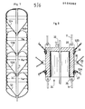
- Figures 7 and 8 are aimed at a variant similar to the previous one, but having several internal envelopes containing helium (the same references have been used in these figures as in the previous figures for similar bodies).
- the base of the lower internal envelope 12i is attached to a pole piece similar to the pole piece 2 previously described, while the upper part of the upper internal envelope 12s is attached to a pole piece similar to the pole piece 3.
- the other poles of said internal envelopes are fixed in intermediate positions on the interpolar link 11 by means of an intermediate pole piece 24, an exemplary embodiment of which is shown in FIG. 8.
- This cup-shaped piece overturned comprises hooking means 25 of the lower strands of the link 11, hooking means 26 of the upper strands of said link and fixing means 27 and 28 of the two internal envelopes concerned 12A and 12B; these latter means are similar to those of the pole piece already described.
- a network of longitudinal reinforcements such as 29 is preferably associated with each internal envelope and is hooked onto means 30 provided for this purpose on the piece 24.
- This additional network constituted by strips of " kevlar "analogous to those already described ensures a resumption of the longitudinal tensions which are applied on the internal envelopes, these longitudinal tensions being higher, in this embodiment, than in the previous one.
- helium conduit already described 22 is extended by a flexible conduit 31 disposed along the axis of the balloon and making it possible to inflate each inner envelope with helium independently by means of solenoid valves 32 provided at each of them. this.
- Such an embodiment conditions increased safety with regard to helium leaks, since the helium volume is divided into several separate volumes (the air leaks from the external envelope being less significant since they can be compensated by air intake).
- the internal envelopes can be constituted by separate envelopes as described above; they can also be produced by means of a single sheath of suitable height, which is clamped at the poles of the internal envelopes, by means of appropriate intermediate pole pieces.
- FIGS. 9 and 10 show the combination of five balloons B 1 , B 2 , B 3 9 B 4 and B 5 joined to each other. These balloons of different diameter make it possible to produce a set of desired horizontal profile. A net 33 retains these balloons and ensures the cohesion of the assembly; the interpolar links of each balloons are fixed on a trellis of beams symbolized at 34, which carries the load.
Abstract
L'invention concerne un ballon aérostatique pilotable et peut en particulier s'appliquer pour la réalisation de ballons de grand volume, libres (dirigeables, ballons spaciaux) ou captifs (ballons de chargement et déchargement de matériel). Ce ballon comprend une enveloppe externe (1) contenant de l'air, un lien interpolaire (11) reliant les pôles inférieur (2) et supérieur (3) de cette enveloppe, un réseau de renforts longitudinaux (8) rattachés aux pôles (2) et (3), un réseau de renforts circonférentiels (7), au moins une enveloppe interne (12) disposée à l'intérieur de la première enveloppe et contenant de l'hélium, cette enveloppe étant apte à s'appuyer lors du gonflage contre l'enveloppe externe et possédant des pôles fixés sur le lien interpolaire (11), enfin des moyens d'admission d'air dans l'enveloppe externe et des moyens d'évacuation de l'air de celle-ci.The invention relates to a controllable aerostatic balloon and can in particular be applied for the production of large volume balloons, free (airships, space balloons) or captive (balloons for loading and unloading of material). This balloon comprises an external envelope (1) containing air, an interpolar link (11) connecting the lower (2) and upper (3) poles of this envelope, a network of longitudinal reinforcements (8) attached to the poles (2 ) and (3), a network of circumferential reinforcements (7), at least one internal envelope (12) disposed inside the first envelope and containing helium, this envelope being capable of being supported during inflation. against the external envelope and having poles fixed on the interpolar link (11), finally means for admitting air into the external envelope and means for evacuating the air therefrom.
Description
L'invention concerne un ballon aérostatique pilotable et peut en particulier s'appliquer pour la réalisation de ballons de grands volumes qui peuvent être libres (dirigeables, ballons spatiaux...) ou captifs (ballons jouant le rôle de grues pour charger et décharger des matériels).The invention relates to a controllable aerostatic balloon and can in particular be applied for the production of balloons of large volumes which can be free (airships, space balloons ...) or captive (balloons playing the role of cranes for loading and unloading materials).
On ne sait pas actuellement fabriquer des ballons de grands volumes, capables de résister à de fortes surpressions tout en présentant un poids modéré compatible avec leur utilisation pratique. Ainsi, les ballons dirigeables actuellement connus pour transporter des charges élevées possèdent des structures d'enveloppe qui ne peuvent, sous peine de détérioration, supporter des surpressions supérieures à 10 millibars environ (différence entre la pression intérieure et la pression externe). Dans ces conditions, les variations des masses gazeuses qui peuvent êtres produites pour ces ballons, sont très largement insuffisantespour assurer leur pilotage aérostatique dans le sens vertical ; celui-ci doit nécessairement être engendré par variation de masses solides ou liquides, ce qui entraîne plusieurs inconvénients bien connus (mauvaise maîtrise du pilotage dans le sens de la descente, obligation d'embarquer des charges supplémentaires, précautions à prendre pour les largages...). En outre, l'équilibre aérostatique de tels ballons est très sensible aux variations thermiques et à la consommation de carburant et le pilotage de ces ballons est délicat.We do not currently know how to make large volumes of balloons, capable of withstanding strong overpressures while having a moderate weight compatible with their practical use. Thus, airships currently known for transporting high loads have envelope structures which cannot, under penalty of deterioration, withstand overpressures greater than approximately 10 millibars (difference between the internal pressure and the external pressure). Under these conditions, the variations in the gas masses which can be produced for these balloons are very largely insufficient to ensure their aerostatic piloting in the vertical direction; this must necessarily be generated by variation of solid or liquid masses, which leads to several well-known drawbacks (poor control of piloting in the direction of descent, obligation to carry additional loads, precautions to be taken for drops. .). In addition, the aerostatic balance of such balloons is very sensitive to thermal variations and to fuel consumption and the piloting of these balloons is delicate.
Il existe, par ailleurs, des ballons spatiaux pilotables destinés à entraîner une charge en vue de l'exploration des couches atmosphériques ; ces ballons qui sont également à faible surpression lorsqu'ils sont de grands volumes,comprennent généralement un ballon porteur gonflé d'un gaz plus léger que l'air tel que l'hélium, et un ballon stabilisateur gonflé d'air,lié au premier et situé au-dessous de celui-ci ; le pilotage s'effectue en faisant varier la pression du ballon stabilisateur à volume constant par admission d'air dans celui-ci ou échappement d'air. Ces systèmes présentent des défauts qui sont liés au fait que les forces de pilotage sont uniquement développées par le ballon stabilisateur : les changements de niveaux sont lents à obtenir et difficiles à contrôler en altitude, et ces ballons sont instables à leur altitude de plafond.There are, moreover, controllable space balloons intended to drive a charge for the exploration of the atmospheric layers; these balloons which are also at low overpressure when they are of large volumes, generally comprise a carrier balloon inflated with a gas lighter than air such as helium, and a stabilizing balloon inflated with air, linked to the first and located below it; piloting is carried out by varying the pressure of the stabilizing balloon at constant volume by admitting air into it or escaping air. These systems have faults which are linked to the fact that the piloting forces are only developed by the stabilized balloon. tor: level changes are slow to obtain and difficult to control at altitude, and these balloons are unstable at their ceiling altitude.
La présente invention se propose de pallier les défauts sus-évoqués des ballons aérostatiques pilotables connus.The present invention proposes to overcome the above-mentioned defects of known controllable aerostatic balloons.
Un objectif essentiel de l'invention est de fournir un ballon aérostatique dont le volume puisse être très élevé (jusqu'à 106 m3) en vue d'être apte à transporter des charges importantes et dont la structure de rétention des gaz soit capable de supporter de très fortes surpressions (plusieurs centaines de millibars).An essential objective of the invention is to provide an aerostatic balloon whose volume can be very high (up to 10 6 m 3) in order to be able to transport large loads and whose gas retention structure is capable of bear very high overpressures (several hundred millibars).
L'invention vise ainsi à fournir un ballon dont le pilotage aérostatique puisse être assuré par variation de masses gazeuses.The invention thus aims to provide a balloon whose aerostatic piloting can be ensured by variation of gas masses.
Un autre objectif de l'invention est d'accroître considérablement l'efficacité des manoeuvres de pilotage (dans le sens vertical) afin d'autoriser des changements de niveaux rapides et bien contrôlés, et ce, quelle que soit l'altitude.Another objective of the invention is to considerably increase the efficiency of piloting maneuvers (in the vertical direction) in order to allow rapid and well-controlled level changes, whatever the altitude.
Un autre objectif est d'obtenir une bonne stabilité du ballon quelle que soit.son altitude et notamment au plafond.Another objective is to obtain good stability of the balloon whatever its altitude and in particular at the ceiling.
En outre, un autre objectif de l'invention est de faciliter au sol les opérations de lancement des ballons.In addition, another objective of the invention is to facilitate balloon launching operations on the ground.
Le ballon aérostatique pilotable conforme-à l'invention comprend :
- . une première enveloppe, dite enveloppe externe, contenant de l'air et possédant une portion approximativement cylindrique et deux pôles, inférieur et supérieur, reliés par un lien interpolaire,
- . un réseau de renforts longitudinaux, s'étendant longitudinalement le long de l'enveloppe externe et rattaché au pôle inférieur et au pôle supérieur de celle-ci,
- . un réseau de renforts circonférentiels s'étendant transversalement autour de l'enveloppe externe,
- . au moins, une deuxième enveloppe, dite enveloppe interne, disposée à l'intérieur de la première enveloppe et contenant un gaz plus léger que l'air, ladite enveloppe interne étant apte à venir s'appuyer lors de son gonflage contre l'enveloppe externe et possédant deux pôles, inférieur et supérieur, fixés sur le lien interpolaire,
- . et des moyens d'admission d'air dans l'enveloppe externe et des moyens d'évacuation d'air de celle-ci. (Il est à noter que par "air", on entend de façon générale le gaz formant l'atmosphère de la planète où évolue le ballon).
- . a first envelope, called external envelope, containing air and having an approximately cylindrical portion and two poles, lower and upper, connected by an interpolar link,
- . a network of longitudinal reinforcements, extending longitudinally along the external envelope and attached to the lower pole and to the upper pole thereof,
- . a network of circumferential reinforcements extending transversely around the external envelope,
- . at least one second envelope, called the internal envelope, disposed inside the first envelope and containing a gas lighter than air, said internal envelope being able to come to bear during its inflation against the external envelope and having two poles, lower and upper, fixed on the interpolar link,
- . and means for admitting air into the external envelope and means for evacuating air therefrom. (It should be noted that by "air", we generally mean the gas forming the atmosphere of the planet where the ball moves).
Ainsi, comme on le comprendra mieux plus loin, la structure d'un tel ballon le rend apte à supporter de fortes surpressions : les tensions développées par la surpression sont en effet reprises dans une large proportion, soit par le réseau de renforts longitudinaux, soit par le réseau de renforts circonférentiels soit par le lien interpolaire. Il est ainsi possible de prévoir des enveloppes minces de très faibles masses surfaciques, tout en soumettant le ballon à des surpressions pouvant atteindre jusqu'à 500 ou 600 millibars. L'enveloppe externe peut en particulier être réalisée en un matériau d'épaisseur approximativement comprise entre 100 et 300 microns, chaque enveloppe interne pouvant être réalisée en un matériau plus mince encore, d'épaisseur approximativement comprise entre 10 et 100 microns.Thus, as will be better understood below, the structure of such a balloon makes it capable of withstanding high overpressures: the tensions developed by the overpressure are in fact taken up in large proportion, either by the network of longitudinal reinforcements, or by the network of circumferential reinforcements or by the interpolar link. It is thus possible to provide thin envelopes of very low surface masses, while subjecting the balloon to overpressures of up to 500 or 600 millibars. The outer casing can in particular be made of a material with a thickness approximately between 100 and 300 microns, each inner casing can be made of an even thinner material, with a thickness approximately between 10 and 100 microns.
De plus, dans un tel ballon où l'enveloppe interne contenant le gaz plus léger que l'air est intégrée à l'enveloppe contenant l'air, les forces de pilotage sont proportionnelles au volume total de l'enveloppe externe et bénéficient d'un effet multiplicateur par rapport aux systèmes classiques à deux ballons séparés.In addition, in such a balloon where the internal envelope containing the gas lighter than air is integrated into the envelope containing the air, the piloting forces are proportional to the total volume of the external envelope and benefit from a multiplier effect compared to conventional systems with two separate balloons.
De façon analogue, les forces réactionnelles s'appliquant sur le ballon en cas de variation d'altitude, sont proportionnelles au volume total de l'enveloppe externe et le ballon bénéficie d'une stabilité améliorée qui demeure bonne à l'altitude de plafond lorsque la quantité d'air est devenue très faible dans l'enveloppe externe.Similarly, the reaction forces applied to the balloon in the event of a change in altitude are proportional to the total volume of the external envelope and the balloon has improved stability which remains good at the ceiling altitude when the amount of air has become very small in the external envelope.
En outre, dans un but de sécurité (compensation d'éventuelles fuites, possibilité de descente rapide), chaque enveloppe interne peut être associée à des moyens de gonflage à l'hélium ou à des moyens de dégonflage de celle-ci.In addition, for safety purposes (compensation for any leaks, possibility of descent rapid), each internal envelope may be associated with helium inflation means or with deflation means thereof.
Le ballon conforme à l'invention peut comprendre une seule enveloppe interne disposée dans son enveloppe externe. Il peut également comprendre plusieurs enveloppes internes agencées à l'intérieur de l'enveloppe externe en fonction des exigences de l'application envisagée. Les moyens de gonflage et de dégonflage associés aux enveloppes internes peuvent, dans ce cas, comporter des moyens de transfert du gaz d'une enveloppe interne à une autre ; ils peuvent également être adaptés pour conférer des pressions différentes aux diverses enveloppes internes.The balloon according to the invention may comprise a single internal envelope disposed in its external envelope. It can also include several internal envelopes arranged inside the external envelope according to the requirements of the envisaged application. The inflation and deflation means associated with the internal envelopes may, in this case, include means for transferring the gas from one internal envelope to another; they can also be adapted to give different pressures to the various internal envelopes.
Selon un mode de réalisation particulier, plusieurs enveloppes internes sont superposées à l'intérieur de l'enveloppe externe, le pôle inférieur de l'enveloppe interne du bas coïncidant sensiblement avec le pôle inférieur de l'enveloppe externe, cependant que le pôle supérieur de l'enveloppe interne du haut coïncide sensiblement avec le pôle supérieur de l'enveloppe externe et que les autres pôles desdites enveloppes internes sont fixés en positions intermédiaires sur le lien interpolaire.According to a particular embodiment, several internal envelopes are superimposed inside the external envelope, the lower pole of the lower internal envelope coinciding substantially with the lower pole of the external envelope, while the upper pole of the upper inner envelope substantially coincides with the upper pole of the outer envelope and that the other poles of said inner envelopes are fixed in intermediate positions on the interpolar link.
Le ballon peut également comprendre plusieurs enveloppes internes disposées côte à côte de façon à venir au gonflage au contact entre elles et/ou au contact de l'enveloppe externe, les pôles inférieurs desdites enveloppes internes coïncidant sensiblement avec le pôle inférieur de l'enveloppe externe, cependant que leurs pôles supérieurs coïncident sensiblement avec le pôle supérieur de ladite enveloppe externe.The balloon can also comprise several internal envelopes arranged side by side so as to inflate in contact with each other and / or in contact with the external envelope, the lower poles of said internal envelopes substantially coinciding with the lower pole of the external envelope. , however that their upper poles substantially coincide with the upper pole of said outer shell.
L'invention s'applique aussi bien dans le secteur des ballons spatiaux, notamment ballons stratosphériques, que dans celui des dirigeables (ballons munis de moyens de propulsion horizontale et éventuellement verticale) ou dans celui des ballons captifs (ballons liés à un câble et pilotés par télécommande pour le transfert de charges).The invention applies equally well in the space balloons sector, in particular stratospheric balloons, as in that of airships (balloons provided with horizontal and possibly vertical propulsion means) or in that of captive balloons (balloons linked to a cable and piloted by remote control for load transfer).
Le ballon conforme à l'invention constitue un module de base qui peut être associé à plusieurs autres modules analogues, soit en superposition verticale, soit en juxtaposition horizontale, soit encore en combinant ces agencements, en vue d'obtenir des ensembles aérostatiques de très grands volumes (dirigeables de grande capacité).The balloon according to the invention constitutes a basic module which can be associated with several other similar modules, either in vertical superposition, or in horizontal juxtaposition, or even by combining these arrangements, with a view to obtaining aerostatic assemblies of very large volumes (high capacity airships).
D'autres caractéristiques, buts et avantages de l'invention se dégageront de la description qui suit en référence aux dessins annexés qui, en présentent à titre d'exemples non limitatifs, des formes de réalisation ; sur ces dessins qui font partie intégrante de la présente description :
- - la figure 1 est une vue en perspective d'un ballon conforme à l'invention,
- - la figure 2 en est une coupe par un plan axial vertical,
- - la figure 3 en est une coupe de détail à échelle dilatée au niveau de l'enveloppe externe,
- - les figures 4a, 4b et 4c sont des vues schématiques montrant entre deux renforts circonféren- tielsl'enveloppe externe dans des états de gonflage croissant,
- - la figure 5 est une vue de détail en coupe montrant la pièce polaire inférieure du ballon,
- --les figures 6a et 6b sont des vues schématiques illustrant la forme du ballon, respectivement dans un état de gonflage réduit (au décollage) et dans un état proche de la plénitude,
- - la figure 7 est une vue schématique en coupe axiale verticale d'un autre mode de réalisation de ballon,
- - la figure 8 est une coupe de détail d'une pièce interpolaire située entre deux enveloppes internes superposées dudit ballon,
- - la figure 9 est une vue schématique en coupe axiale verticale d'un ensemble aérostatique réalisé au moyen de plusieurs ballons conformes à l'invention,
- - la figure 10 est une coupe par un plan horizontal de cet ensemble.
- FIG. 1 is a perspective view of a balloon according to the invention,
- FIG. 2 is a section through a vertical axial plane,
- FIG. 3 is a detail section thereof on a dilated scale at the level of the external envelope,
- FIGS. 4a, 4b and 4c are schematic views showing between two circumferential reinforcements the external envelope in states of increasing inflation,
- FIG. 5 is a detail view in section showing the lower pole piece of the balloon,
- FIGS. 6a and 6b are schematic views illustrating the shape of the balloon, respectively in a reduced inflation state (on takeoff) and in a state close to fullness,
- FIG. 7 is a schematic view in vertical axial section of another embodiment of the balloon,
- FIG. 8 is a detail section of an interpolar part situated between two superimposed internal envelopes of said balloon,
- FIG. 9 is a schematic view in vertical axial section of an aerostatic assembly produced by means of several balloons in accordance with the invention,
- - Figure 10 is a section through a horizontal plane of this assembly.
Le ballon aérostatique pilotable représenté à titre d'exemple aux figures 1 à 6 constitue le module de base le plus simple qui peut être utilisé seul ou en combinaison avec d'autres modules, pour réaliser un ballon spatial, un dirigeable, ou un ballon captif de transfert de charge.The controllable aerostatic balloon shown by way of example in FIGS. 1 to 6 constitutes the simplest basic module which can be used alone or in combination with other modules, to make a space balloon, an airship, or a captive load transfer balloon.
Ce ballon comprend en premier lieu une enveloppe externe 1 qui est réalisée en assemblant des fuseaux rectangulaires, par tout moyen connu,le long de leurs bords rectilignes. Cette enveloppe comporte ainsi une portion cylindrique la qui se prolonge par des portions extrêmes froncées dont les bords sont rattachés à des pièces polaires 2 et 3 disposées aux pôles,inférieur et supérieurde l'enveloppe sur l'axe de celle-ci.This balloon comprises in the first place an
La fabrication d'une telle enveloppe possédant une portion cylindrique ia peut être réalisée conformément au procédé décrit dans le brevet FR n° 2 472 971 au nom du demandeur.The manufacture of such an envelope having a cylindrical portion ia can be carried out according to the method described in patent FR No. 2,472,971 in the name of the applicant.
Le matériau constitutif de l'enveloppe externe 1 est un matériau composite étanche à l'air, possédant en l'exemple trois couches comme le représente la figure 3 : du côté extérieur un film polyester thermoscellable 4, du côté intérieur un film polyéthylène soudable 5 et, entre les deux, un tissu "kevlar-polyester" 6. L'ensemble présente une épaisseur de l'ordre de 200 microns.The material constituting the
Le tissu 6 comprend une trame en polyester disposée dans le sens circonférentiel et une chaîne en "kevlar" disposée dans le sens longitudinal. Il possède ainsi une résistance dissymétrique, plus élevée dans le sens longitudinal que dans le sens circonférentiel ; de plus, il est inextensible dans le sens longitudinal (par "inextensible" on entend un matériau dont l'allongement élastique ne dépasse pas 1 à 2 % environ), alors que, dans le sens circonférentiel, le matériau possède une élasticité plus importante (allongement de l'ordre de 10 % environ).The
L'enveloppe externe 1 est entourée d'un réseau de renforts circonférentiels tels que 7 et d'un réseau de renforts longitudinaux tels que 8.The
Les renforts circonférentiels 7 sont situés dans des plans perpendiculaires à l'axe de l'enveloppe, répartis sur la hauteur de celle-ci. Chaque renfort circonférentiel 7 est constitué par une bande en un matériau inextensible de haute résistance, par exemple "Kevlar" de 5/10e mm d'épaisseur sur 20 à 50 mm de largeur ; les deux extrémités de chaque bande sont assemblées par collage l'une sur l'autre.The
Chaque bande 7 est liée en quelques points à l'enveloppe externe 1, de façon à pouvoir jouer par rapport à celle-ci en vue de ne lui transmettre que des efforts faibles par rapport à ceux supportés par ladite bande. En l'exemple, les fixations de chaque bande 7 sont réalisées au moyen de portions conjuguées 8 et 9 de matériaux d'accrochage du type "Velcro", qui sont collées en regard, d'une part, sur l'enveloppe externe 1, d'autre part sur la bande concernée 7.Each
Chaque bande de renfort 7 se trouve ainsi fixée autour et à l'extérieur de l'enveloppe externe 1 et, pour l'état gonflé de cette enveloppe, vient au contact de celle-ci sur toute sa périphérie sans lui transmettre de contraintes notables.Each reinforcing
Par ailleurs, les renforts longitudinaux 8 sont situés dans des plans méridiens répartis autour de l'enveloppe externe ; ils sont positionnés à l'extérieur du réseau de renforts circonférentiels, par des moyens de positionnement qui les maintiennent. En l'exemple, ces moyens de positionnement sont constitués par des ceintures souples 10 (en tissu ou autres) qui sont traversées par lesdits renforts longitudinaux.Furthermore, the
Chaque renfort 8 est réalisé en un matériau inextensible de haute résistance et peut être constitué comme précédemment par des bandes de "kevlar".Each
Les renforts longitudinaux 8 s'étendent d'un seul tenant entre les pôles inférieur et supérieur de l'enveloppe externe et sont fixés au niveau de ces pôles sur les pièces polaires 2 et 3.The
L'enveloppe externe 1 présente dans le sens longitudinal une longueur supérieure à la longueur de chaque bande de renfort longitudinal 8, de façon que, à l'état entièrement gonflé, les efforts longitudinaux soient essentiellement supportés par le réseau de renforts longitudinaux 8.The
Comme le schématise la figure 4a, à l'état non totalement gonflé, l'enveloppe externe 1 possède des plis périphériques P situés entre les renforts circonférentiels. Ainsi lors du gonflage, des lobes apparaissent entre les renforts circonférentiels, et sont d'autant plus prononcés que la surpression dans l'enveloppe est plus grande (figures 4b et 4c).As shown in Figure 4a, in the not fully inflated state, the
Par ailleurs, les pièces polaires 2 et 3 sont réunies par un lien interpolaire 11 inextensible s'étendant le long de l'axe de l'enveloppe externe 1 ; en l'exemple, ce lien est constitué par un faisceau de bandes en un matériau inextensible de haute résistance, notamment "kevlar".Furthermore, the
La longueur du lien interpolaire 11 est inférieure à celle des fuseaux formant l'enveloppe externe et est ajustée en fonction des divers paramètres du ballon pour obtenir la forme externe désirée (cf brevet FR n° 2 472 971 déjà évoqué).The length of the
De plus, le ballon comprend une enveloppe interne 12 qui est située à l'intérieur de l'enveloppe externe 1 ; cette enveloppe 12 est fabriquée d'une manière analogue à l'enveloppe externe par assemblage de fuseaux rectangulaires dont les bords supérieur et inférieur sont réunis et fixés sur les pièces polaires 2 et 3.In addition, the balloon comprises an
L'enveloppe interne 12 possède ainsi une portion cylindrique 12a et le diamètre de celle-ci est dimensionné pour correspondre à celui de la portion cylindrique 'la de l'enveloppe externe gonflée au maximum,de façon que cette portion 12a vienne s'appuyer au gonflage contre ladite portion 1a.The
Ainsi, l'enveloppe interne n'a à supporter que de faibles contraintes et elle peut être réalisée en un matériau très mince d'épaisseur inférieure à celle de l'enveloppe externe, en particulier de l'ordre de 50 microns ; ce matériau peut être un matériau composite du type comprenant une couche de "mylar"habillée d'un revêtement d'aluminium afin de la rendre étanche à l'hélium.Thus, the internal envelope has to withstand only low stresses and it can be made of a very thin material with a thickness less than that of the external envelope, in particular of the order of 50 microns; this material can be a composite material of the type comprising a layer of "mylar" coated with an aluminum coating in order to make it helium-tight.
L'enveloppe interne est gonflée au moyen d'hélium (ou autre gaz plus léger que l'air), cependant que l'enveloppe externe est gonflée d'air.The inner shell is inflated with helium (or other gas lighter than air), while the outer shell is inflated with air.
Le gonflage à l'hélium peut s'effectuer uniquement au sol lors du lancement du ballon, la pièce polaire supérieure étant pourvue d'un clapet de sécurité pour permettre un échappement en cas de surpression intérieure supérieure à une limite.Helium inflation can only be carried out on the ground when the balloon is launched, the upper pole piece being provided with a safety valve to allow an escape in the event of an internal overpressure greater than a limit.
Le ballon peut également être doté de moyens embarqués de gonflage et de dégonflage de l'enveloppe interne, en vue d'accroître la sécurité du vol (compensation de fuite, faculté d'augmenter l'efficacité du pilotage en cas de danger).The balloon can also be fitted with on-board means of inflating and deflating the internal envelope, in order to increase flight safety (leakage compensation, ability to increase the efficiency of piloting in the event of danger).
Dans tous les cas, le ballon est doté de moyens embarqués d'admission d'air dans l'enveloppe externe et de moyens d'évacuation d'air ; ces moyens sont utilisés au sol pour le gonflage de ladite enveloppe et, en vol, pour son pilotage (une admission d'air engendrant une descente du ballon et une évacuation d'air engendrant une montée).In all cases, the balloon is fitted with on-board means for admitting air into the external envelope and means for discharging air; these means are used on the ground for inflating said envelope and, in flight, for piloting it (an air intake causing a descent of the balloon and an air evacuation causing a rise).
La figure 5 représente en coupe axiale la pièce polaire inférieure 2 par l'intermédiaire de laquelle s'effectue cette admission ou cette évacuation d'air.FIG. 5 shows in axial section the
Cette pièce forme une chambre interne 13 qui communique par des lumières 14 avec l'intérieur de l'enveloppe externe 1. A cet effet, la partie basse de cette enveloppe externe est fixée de façon étanche autour de.ladite pièce au-dessous des lumières 14, cependant que la partie basse de l'enveloppe interne 12 est fixée de façon analogue au-dessus desdites lumières 14.This part forms an internal chamber 13 which communicates through lights 14 with the interior of the
La fixation de chaque enveloppe 1 ou 12 s'effectue autour de la pièce 2 grâce à un bourrelet annulaire 15 solidaire du bord de l'enveloppe et à un collier de serrage 16.Each
En outre, la pièce polaire 2 comporte extérieurement des moyens d'accrochage tels que 17 du faisceau de bandes formant le lien interpolaire 11 et des moyens d'accrochage tels que 18 des bandes formant le réseau de renforts longitudinaux 8 ; elle porte également à sa partie basse un moyen d'accrochage 19 de la charge.In addition, the
La pièce 2 est équipée d'une vanne trois voies 20, qui permet soit de réaliser une évacuation d'air par une sortie 20a, soit d'admettre de l'air comprimé provenant d'un turbo-compresseur (ou autre moyen équivalent) à travers un conduit 21. Ce turbo-compresseur est embarqué et peut être logé avec la charge.The
Le gonflage à l'hélium de l'enveloppe interne 12 s'effectue à travers un conduit 22 qui traverse de façon étanche la pièce 2 pour déboucher en partie haute de celle-ci par un orifice 22a situé sur l'axe du ballon. Pour éviter toute détérioration de l'enveloppe interne, un manchon poreux 23 est prévu à l'intérieur de celle-ci autour de l'orifice 22a ; ce manchon s'étend d'un pôle à l'autre : lorsque le conduit 22 est connecté à une source d'hélium de haute pression, ce manchon permet au gaz parvenant dans l'enveloppe interne de se détendre sans risquer de détériorer cette dernière. Bien entendu, un clapet referme le conduit 22 lorsqu'il est déconnecté de la source d'hélium.The
Les figures 6a et 6b montrent le ballon ci-dessus décrit dans deux états de gonflage différents.Figures 6a and 6b show the balloon described above in two different inflation states.
Lorsque le ballon prend de l'altitude (pression extérieure décroissante), le volume de son enveloppe interne qui contient une quantité d'hélium constante, croft, cependant que la masse d'air de l'enveloppe externe diminue, le volume de l'ensemble du ballon demeurant sensiblement constant.When the balloon takes altitude (decreasing external pressure), the volume of its internal envelope which contains a constant amount of helium, croft, while that the mass of air of the external envelope decreases, the volume of the entire balloon remaining substantially constant.
Dans un tel système, l'on peut démpntrer qu'une admission d'air (ou une évacuation d'air) engendrant une augmentation Δp (ou diminution), de la pression dans l'enveloppe externe produit une force verticale E dirigée vers le bas (ou vers le haut), telle que :![]()
![]()
On observe que cette force de pilotage est proportionnelle à V : volume total du ballon, et non au seul volume d'air contenu dans l'enveloppe externe.It is observed that this piloting force is proportional to V: total volume of the balloon, and not only to the volume of air contained in the external envelope.
Au contraire, dans le cas de deux ballons séparés (ballon porteur gonflé d'hélium de volume V'1 et ballon stabilisateur contenant de l'air de volume V'2), cette force de pilotage E' est :![]()
![]()
En conséquence V étant très supérieur à V'2, les forces de pilotage bénéficient dans le ballon de l'invention, d'un facteur de multiplication égal à ![]()
![]()
De la même façon, les forces de réaction s'opposant à une variation accidentelle d'altitude sont multipliées par ce facteur, de sorte que la stabilité du ballon est notablement améliorée, en particulier à l'altitude de plafond.In the same way, the reaction forces opposing an accidental change in altitude are multiplied by this factor, so that the stability of the balloon is notably improved, in particular at the ceiling altitude.
Par ailleurs, la structure du ballon permet de gonfler ses enveloppes à des surpressions considérablement plus élevées que celles que peuvent supporter les ballons classiques. En effet, les efforts de tension de l'enveloppe interne sont repris dans une large proportion par l'enveloppe externe et par le lien interpolaire, cependant que les efforts de tension de l'enveloppe externe sont repris par le lien interpolaire, le réseau longitudinal 8 et le réseau circonférentiel 7.In addition, the structure of the balloon makes it possible to inflate its envelopes to considerably higher overpressures than those which conventional balloons can withstand. Indeed, the stresses of tension of the internal envelope are taken up in a large proportion by the external envelope and by the interpolar link, while that the stresses of tension of the external envelope are taken up by the interpolar link, the
Il est à noter que la dissymétrie de résistance de l'enveloppe externe et sa structure lobée lorsqu'elle est gonflée, contribuent à accroître la valeur limite de la surpression admissible ; en effet, l'expression de cette valeur limite comporte un terme proportionnel à ![]()
![]()
Dans chaque application, les paramètres du ballon (densité du réseau circonférentiel, densité du réseau longitudinal,...) seront ajustés de façon à optimiser le champ de contraintes s'appliquant sur les enveloppes, de sorte que le matériau de celles-ci travaille dans les meilleures conditions, c'est-à-dire,dans chaque direction,à sa limite élastique multipliée par un coefficient de sécurité : le meilleur compromis surpression/poids peut 'ainsi être obtenu.In each application, the parameters of the balloon (density of the circumferential network, density of the longitudinal network, etc.) will be adjusted so as to optimize the stress field applied to the envelopes, so that the material of these works under the best conditions, that is to say, in each direction, to its elastic limit multiplied by a safety factor: the best compromise pressure / weight can 'be obtained.
Il est à noter que, en cas d'apparition locale de surtensions accidentelles, la structure précédemment décrite permet d'obtenir, au niveau du lobe concerné de l'enveloppe externe, un dépassement de la limite d'élasticité intervenant d'abord dans le sens circonférentiel, de sorte que l'éventuelle rupture prenne la forme d'une fente longitudinale limitée par les deux bandes de renforts circonférentiels qui bordent le lobe concerné. On évite ainsi un éclatement brusque du ballon.It should be noted that, in the event of local occurrence of accidental overvoltages, the structure described above makes it possible to obtain, at the level of the lobe concerned of the external envelope, an exceeding of the elastic limit intervening first in the circumferential sense, so that the possible rupture takes the form of a longitudinal slit limited by the two bands of circumferential reinforcements which border the lobe concerned. This avoids a sudden bursting of the balloon.
Le lancement du ballon au sol est effectué en gonflant son enveloppe externe à l'air. Pendant ce gonflage, le ballon reste étendu sur le sol, cette position permettant de le maîtriser plus facilement que s'il était dressé verticalement (pendant cette phase, le ballon peut, le cas échéant, être disposé à l'abri dans un hangar de hauteur courante, ayant une forme allongée).The balloon is launched on the ground by inflating its outer envelope with air. During this inflation, the balloon remains extended on the ground, this position making it easier to control it than if it was erected vertically (during this phase, the balloon can, if necessary, be placed under cover in a hangar of running height, having an elongated shape).
Ensuite, la quantité d'hélium nécessaire à la mission est admise dans l'enveloppe interne ; le ballon se dresse progressivement jusqu'à son envol. Il est à noter que le ballon peut être aisément manipulé sans contact avec les enveloppes fragiles, en le saisissant par les bandes longitudinales 8 ou circonférentielles 7.Then, the quantity of helium necessary for the mission is admitted into the internal envelope; the balloon rises gradually until it takes off. It should be noted that the balloon can be easily manipulated without contact with the fragile envelopes, by gripping it by the longitudinal 8 or
Lors du décollage, l'enveloppe interne peut avoir un volume de l'ordre du tiers ou du quart du volume total du ballon, tandis qu'au plafond, elle occupe la quasi-totalité du volume de ce dernier, la quantité d'air résiduel dans l'enveloppe externe étant faible. La surpression intérieure relative régnant dans l'enveloppe externe et dans l'enveloppe interne peut être de l'ordre de 500 millibars.During takeoff, the internal envelope can have a volume of the order of a third or a quarter of the total volume of the balloon, while at the ceiling, it occupies almost the entire volume of the latter, the amount of air residual in the outer shell being small. The relative internal overpressure prevailing in the external envelope and in the internal envelope can be of the order of 500 millibars.
Les figures 7 et 8 visent une variante similaire à la précédente, mais possédant plusieurs enveloppes internes contenant de l'hélium (on a repris sur ces figures les mêmes références qu'aux figures précédentes pour des organes similaires). La base de l'enveloppe interne inférieure 12i est attachée à une pièce polaire analogue à la pièce polaire 2 précédemment décrite, cependant que la partie haute de l'enveloppe interne supérieure 12s est rattachée à une pièce polaire analogue à la pièce polaire 3.Figures 7 and 8 are aimed at a variant similar to the previous one, but having several internal envelopes containing helium (the same references have been used in these figures as in the previous figures for similar bodies). The base of the lower
Les autres pôles desdites enveloppes internes sont fixés en positions intermédiaires sur le lien interpolaire 11 au moyen d'une pièce polaire intermédiaire 24 dont un exemple de réalisation est représenté à la figure 8.The other poles of said internal envelopes are fixed in intermediate positions on the
Cette pièce, en forme de coupeUe renversée,comprend des moyens d'accrochage 25 des brins inférieurs du lien 11, des moyens d'accrochage 26 des brins supérieurs dudit lien et des moyens de fixation 27 et 28 des deux enveloppes internes concernées 12A et 12B ; ces derniers moyens sont analogues à ceux de la pièce polaire déjà décrite.This cup-shaped piece overturned, comprises hooking means 25 of the lower strands of the
De plus, dans ce cas, un réseau de renforts longitudinaux tel que 29 est de préférence associé à chaque enveloppe interne et vient s'accrocher sur des moyens 30 prévus à cet effet sur la pièce 24. Ce réseau supplémentaire constitué par des bandes de "kevlar" analogues à celles déjà décrites assure une reprise des tensions longitudinales qui s'appliquent sur les enveloppes internes, ces tensions longitudinales étant plus élevées, dans ce mode de réalisation, que dans le précédent.In addition, in this case, a network of longitudinal reinforcements such as 29 is preferably associated with each internal envelope and is hooked onto
En outre, le conduit d'hélium déjà décrit 22 se prolonge par un conduit souple 31 disposé selon l'axe du ballon et permettant de gonfler indépendamment chaque enveloppe interne à l'hélium grâce à des électrovannes 32 prévues au niveau de chacune de celles-ci.In addition, the helium conduit already described 22 is extended by a flexible conduit 31 disposed along the axis of the balloon and making it possible to inflate each inner envelope with helium independently by means of
Un tel mode de réalisation conditionne une sécurité accrue à l'égard des fuites d'hélium, du fait que le volume d'hélium est divisé en plusieurs volumes séparés (les fuites d'air de l'enveloppe externe étant moins importantes puisqu'elles peuvent être compensées par admission d'air).Such an embodiment conditions increased safety with regard to helium leaks, since the helium volume is divided into several separate volumes (the air leaks from the external envelope being less significant since they can be compensated by air intake).
Il est à noter que les enveloppes internes peuvent être constituées par des enveloppes séparées comme ci-dessus décrit ; elles peuvent également être réalisées au moyen d'une gaine unique de hauteur adaptée, qui est serrée au niveau des pôles des enveloppes internes, au moyen de pièces polaires intermédiaires appropriées.It should be noted that the internal envelopes can be constituted by separate envelopes as described above; they can also be produced by means of a single sheath of suitable height, which is clamped at the poles of the internal envelopes, by means of appropriate intermediate pole pieces.
Les ballons décrits précédemment peuvent être combinés pour réaliser des ensembles aérostatiques adaptés à chaque application. Par exemple, on a représenté aux figures 9 et 10 la combinaison de cinq ballons B1, B2, B39 B4 et B5 accolés les uns aux autres. Ces ballons de diamètre différent permettent de réaliser un ensemble de profil horizontal désiré. Un filet 33 retient ces ballons et assure la cohésion de l'ensemble ; les liens interpolaires de chacun des ballons sont fixés sur un treillis de poutrelles symbolisé en 34, qui porte la charge.The balloons described above can be combined to produce aerostatic assemblies adapted to each application. For example, FIGS. 9 and 10 show the combination of five balloons B 1 , B 2 , B 3 9 B 4 and B 5 joined to each other. These balloons of different diameter make it possible to produce a set of desired horizontal profile. A net 33 retains these balloons and ensures the cohesion of the assembly; the interpolar links of each balloons are fixed on a trellis of beams symbolized at 34, which carries the load.
On peut ainsi réaliser par combinaison de ballons conformes à l'invention des dirigeables aérostatiques qui seront équipés de groupes de propulsion horizontale et de tous les organes auxiliaires nécessaires (dérive...), La stabilité purement aérostatique de ces engins leur permet de décoller et de demeurer stable en altitude sans vitesse relative ; de plus leur pilotage dans le sens vertical peut être effectué par variation de la masse d'air qu'ils contiennent, les changements de niveaux étant faciles à contrôler et rapides à obtenir.It is thus possible, by combining balloons in accordance with the invention, aerostatic airships which will be equipped with horizontal propulsion groups and all the necessary auxiliary organs (drift, etc.). The purely aerostatic stability of these craft allows them to take off and to remain stable at altitude without relative speed; moreover their piloting in the vertical direction can be carried out by variation of the mass of air which they contain, the changes of levels being easy to control and quick to obtain.
Claims (13)
Applications Claiming Priority (2)
| Application Number | Priority Date | Filing Date | Title |
|---|---|---|---|
| FR8418798A FR2574369B1 (en) | 1984-12-06 | 1984-12-06 | PILOTABLE AEROSTATIC BALLOON |
| FR8418798 | 1984-12-06 |
Publications (2)
| Publication Number | Publication Date |
|---|---|
| EP0184262A1 true EP0184262A1 (en) | 1986-06-11 |
| EP0184262B1 EP0184262B1 (en) | 1988-04-27 |
Family
ID=9310399
Family Applications (1)
| Application Number | Title | Priority Date | Filing Date |
|---|---|---|---|
| EP85201975A Expired EP0184262B1 (en) | 1984-12-06 | 1985-11-26 | Steerable aerostatic balloon |
Country Status (8)
| Country | Link |
|---|---|
| US (1) | US4711416A (en) |
| EP (1) | EP0184262B1 (en) |
| JP (1) | JPS62501407A (en) |
| BR (1) | BR8507096A (en) |
| CA (1) | CA1255644A (en) |
| DE (1) | DE3562354D1 (en) |
| FR (1) | FR2574369B1 (en) |
| WO (1) | WO1986003469A1 (en) |
Cited By (6)
| Publication number | Priority date | Publication date | Assignee | Title |
|---|---|---|---|---|
| FR2659933A1 (en) * | 1990-03-20 | 1991-09-27 | R P Dev Sarl | System for taking up longitudinal stresses at the end of a flexible structure, and its method of manufacture |
| EP0321012B1 (en) * | 1987-12-02 | 1992-04-15 | CENTRE NATIONAL D'ETUDES SPATIALES (C.N.E.S.) Etablissement public, scientifique et | Baloon adapted to perform a self-governing and reversible flight between the ground of a planet with an atmosphere and a predetermined altitude |
| WO1996015939A1 (en) * | 1994-11-21 | 1996-05-30 | Franco Carloni | Air balloon containing inert gas |
| FR2867450A1 (en) * | 2004-03-09 | 2005-09-16 | Francois Nicolas Jean Villon | Load lifting balloon, has external envelop filled with helium, internal envelope to be filled with air, and pole piece connecting in airtight manner poles of envelopes, which are connected by inter-pole connecting material |
| CN105546332A (en) * | 2015-09-21 | 2016-05-04 | 王明华 | Method and device for filling air balloon with gas mixture of helium gas and air |
| CN108100211A (en) * | 2016-11-25 | 2018-06-01 | 海口未来技术研究院 | Aerostatics |
Families Citing this family (39)
| Publication number | Priority date | Publication date | Assignee | Title |
|---|---|---|---|---|
| US4850551A (en) * | 1987-12-14 | 1989-07-25 | Lockheed Corporation | Propulsion system for a buoyant vehicle |
| DE4023112C2 (en) * | 1990-07-20 | 1994-06-09 | Gehse Hartmut | Aerostatic open or closed free balloon, especially for use at high altitudes |
| FR2681306A1 (en) * | 1991-09-16 | 1993-03-19 | Bigotte Claude | Lift method for lighter-than-air machines, with independence of ballasting |
| US5297763A (en) * | 1993-03-01 | 1994-03-29 | Cazort Brad A | Safety balloon apparatus |
| UA43849C2 (en) * | 1993-07-30 | 2002-01-15 | Інтернешнл Малті Медіа Корпорейшн | TELECOMMUNICATION SYSTEM, LONG COMMUNICATION METHOD AND REPRODUCTION STATION FOR TELECOMMUNICATION SYSTEM. |
| US20030236070A1 (en) | 2002-06-25 | 2003-12-25 | Seligsohn Sherwin I. | Sub-orbital, high altitude communications system |
| US5743786A (en) * | 1996-05-30 | 1998-04-28 | Lindsey; Alan | Balloon face polyhedra |
| US5810286A (en) * | 1996-10-11 | 1998-09-22 | Matsler; Winfield R. | Lighter-than-air aircraft |
| US6016991A (en) * | 1997-01-24 | 2000-01-25 | Lowe, Jr.; Charles S. | Evacuated rotating envelope aircraft |
| US6270036B1 (en) | 1997-01-24 | 2001-08-07 | Charles S. Lowe, Jr. | Blown air lift generating rotating airfoil aircraft |
| US6427943B2 (en) * | 1998-10-07 | 2002-08-06 | Fuji Jukogyo Kabushiki Kaisha | Stratospheric airship |
| FR2790440B1 (en) | 1999-03-02 | 2001-06-01 | Regipa And Partners Dev | DEVICE AND METHOD FOR ANCHORING A FABRIC OF FLEXIBLE MATERIAL TO A MOORING ELEMENT |
| FR2790441B1 (en) | 1999-03-02 | 2001-06-01 | Regipa And Partners Dev | AEROSTATIC ASSEMBLY INCLUDING A PLURALITY OF PRESSURIZED BALLOONS |
| AU2000272999A1 (en) | 2000-09-07 | 2002-03-22 | Interactive Star | Device and method for hooking a band of flexible material to a securing device |
| AU2000274254A1 (en) | 2000-10-03 | 2002-04-15 | Interactive Star | Aerostatic assembly comprising a plurality of pressurised balloons |
| CN1331710C (en) * | 2000-12-22 | 2007-08-15 | 张涛 | Hard-shell balloon or airship using hydrogen safety and able to control its lifting |
| JP2003175895A (en) * | 2001-12-13 | 2003-06-24 | Inst Of Space & Astronautical Science | Film structure |
| WO2003064253A1 (en) * | 2002-01-30 | 2003-08-07 | Konrad Walter | Aircraft |
| FR2877315B1 (en) * | 2004-10-29 | 2007-02-02 | Eads Space Transp Sas Soc Par | DEVICE FOR CONTROLLING THE DEPLOYMENT OF INFLATABLE STRUCTURES |
| US8704397B2 (en) * | 2005-06-09 | 2014-04-22 | Yehuda Roseman | System for producing electricity from jetstreams and tower therefor |
| US7552893B2 (en) * | 2005-09-28 | 2009-06-30 | 21St Century Airship Technologies Inc. | Airship & method of operation |
| US8091826B2 (en) * | 2007-04-24 | 2012-01-10 | Michael Todd Voorhees | Aerostatic buoyancy control system |
| JP5528687B2 (en) * | 2008-07-15 | 2014-06-25 | 独立行政法人 宇宙航空研究開発機構 | Pressure-resistant large membrane structure |
| WO2012112913A1 (en) * | 2011-02-17 | 2012-08-23 | World Surveillance Group, Inc. | An airship and a method for controlling the airship |
| WO2012118731A2 (en) * | 2011-03-01 | 2012-09-07 | Ciampa John A | Lighter-than-air systems, methods, and kits for obtaining aerial images |
| US8505847B2 (en) | 2011-03-01 | 2013-08-13 | John Ciampa | Lighter-than-air systems, methods, and kits for obtaining aerial images |
| US9694910B2 (en) | 2013-02-22 | 2017-07-04 | World View Enterprises Inc. | Near-space operation systems |
| US20160083068A1 (en) * | 2013-11-17 | 2016-03-24 | Austyn D. Crites | High Altitude Balloon |
| US9580161B1 (en) * | 2013-12-20 | 2017-02-28 | X Development Llc | Reinforcing ripstop tape for burst mitigation |
| US9463863B1 (en) | 2013-12-30 | 2016-10-11 | Google Inc. | Superpressure balloon with ballonet cut from contiguous gores |
| US9573671B1 (en) * | 2013-12-31 | 2017-02-21 | X Development Llc | Fabric diffuser for high flowrate inflation |
| US9327817B1 (en) * | 2014-02-03 | 2016-05-03 | Google Inc. | Ballonet for a balloon |
| US9327818B1 (en) * | 2014-02-05 | 2016-05-03 | Google Inc. | Ballonet for a balloon |
| EP3268279A4 (en) | 2015-03-09 | 2018-08-08 | World View Enterprises Inc. | Rigidized assisted opening system for high altitude parafoils |
| US9540091B1 (en) * | 2016-02-11 | 2017-01-10 | World View Enterprises Inc. | High altitude balloon systems and methods |
| US20180093750A1 (en) * | 2016-10-05 | 2018-04-05 | The Boeing Company | Puffing propulsion for super pressure balloons |
| US10124875B1 (en) | 2017-01-09 | 2018-11-13 | World View Enterprises Inc. | Continuous multi-chamber super pressure balloon |
| US10336432B1 (en) | 2017-01-09 | 2019-07-02 | World View Enterprises Inc. | Lighter than air balloon systems and methods |
| US11577813B2 (en) * | 2020-12-14 | 2023-02-14 | Aerostar International, Llc | Outer membrane for aerial vehicles |
Citations (3)
| Publication number | Priority date | Publication date | Assignee | Title |
|---|---|---|---|---|
| DE239989C (en) * | ||||
| US3432122A (en) * | 1967-06-19 | 1969-03-11 | Goodyear Aerospace Corp | Combination ballonet and dilation system for balloons |
| GB2026971A (en) * | 1978-08-04 | 1980-02-13 | Solar Srl | An aerostatic balloon of air type heated by solar energy |
Family Cites Families (13)
| Publication number | Priority date | Publication date | Assignee | Title |
|---|---|---|---|---|
| US2038671A (en) * | 1930-12-06 | 1936-04-28 | Olan Mary Ellen | Airship |
| DE696253C (en) * | 1938-06-08 | 1940-09-16 | Luftschiffbau Zeppelin G M B H | Captive balloon |
| US2492800A (en) * | 1948-08-16 | 1949-12-27 | Dewey And Almy Chem Comp | Fast rising sounding balloon |
| US3180590A (en) * | 1963-01-23 | 1965-04-27 | Aereon Corp | Pressurized airship |
| US3391883A (en) * | 1965-04-19 | 1968-07-09 | Schjeldahl Co G T | Gore tailoring |
| US3871603A (en) * | 1974-05-30 | 1975-03-18 | Schjeldahl Co G T | Fin attachment for tethered balloon structures |
| US3971533A (en) * | 1975-02-25 | 1976-07-27 | Slater Saul I | Convertible airship |
| US4032086A (en) * | 1975-10-20 | 1977-06-28 | William Douglas Cooke | Aerostats and aquastats |
| US4033527A (en) * | 1976-02-03 | 1977-07-05 | Raven Industries, Inc. | Deflation cap for pressurized hot air airship |
| US4090682A (en) * | 1976-03-25 | 1978-05-23 | Raven Industries, Inc. | Pressure and hot air relief vents for a pressurized hot air airship |
| FR2464898A1 (en) * | 1979-09-06 | 1981-03-20 | Centre Nat Etd Spatiales | PROCESS FOR PRODUCING A CONTAINER WITH LOBED SYMMETRIC STRUCTURE AND CONTAINER PRODUCED ACCORDING TO SAID METHOD |
| FR2472971A1 (en) * | 1980-01-04 | 1981-07-10 | Centre Nat Etd Spatiales | METHOD FOR PRODUCING AN ENVELOPE, ESPECIALLY FOR SPATIAL BALLOONS, A REALIZED ENVELOPE, AND USE THEREOF IN THE AEROSPACE FIELD |
| JPH0233559B2 (en) * | 1982-08-19 | 1990-07-27 | Fujita Corp | GASUKIKYU |
-
1984
- 1984-12-06 FR FR8418798A patent/FR2574369B1/en not_active Expired
-
1985
- 1985-11-25 BR BR8507096A patent/BR8507096A/en not_active IP Right Cessation
- 1985-11-25 JP JP60505297A patent/JPS62501407A/en active Pending
- 1985-11-25 WO PCT/FR1985/000332 patent/WO1986003469A1/en unknown
- 1985-11-26 DE DE8585201975T patent/DE3562354D1/en not_active Expired
- 1985-11-26 EP EP85201975A patent/EP0184262B1/en not_active Expired
- 1985-12-05 US US06/804,887 patent/US4711416A/en not_active Expired - Lifetime
- 1985-12-05 CA CA000496921A patent/CA1255644A/en not_active Expired
Patent Citations (3)
| Publication number | Priority date | Publication date | Assignee | Title |
|---|---|---|---|---|
| DE239989C (en) * | ||||
| US3432122A (en) * | 1967-06-19 | 1969-03-11 | Goodyear Aerospace Corp | Combination ballonet and dilation system for balloons |
| GB2026971A (en) * | 1978-08-04 | 1980-02-13 | Solar Srl | An aerostatic balloon of air type heated by solar energy |
Cited By (8)
| Publication number | Priority date | Publication date | Assignee | Title |
|---|---|---|---|---|
| EP0321012B1 (en) * | 1987-12-02 | 1992-04-15 | CENTRE NATIONAL D'ETUDES SPATIALES (C.N.E.S.) Etablissement public, scientifique et | Baloon adapted to perform a self-governing and reversible flight between the ground of a planet with an atmosphere and a predetermined altitude |
| FR2659933A1 (en) * | 1990-03-20 | 1991-09-27 | R P Dev Sarl | System for taking up longitudinal stresses at the end of a flexible structure, and its method of manufacture |
| WO1996015939A1 (en) * | 1994-11-21 | 1996-05-30 | Franco Carloni | Air balloon containing inert gas |
| US5931412A (en) * | 1994-11-21 | 1999-08-03 | Carloni; Franco | Air balloon containing inert gas |
| FR2867450A1 (en) * | 2004-03-09 | 2005-09-16 | Francois Nicolas Jean Villon | Load lifting balloon, has external envelop filled with helium, internal envelope to be filled with air, and pole piece connecting in airtight manner poles of envelopes, which are connected by inter-pole connecting material |
| CN105546332A (en) * | 2015-09-21 | 2016-05-04 | 王明华 | Method and device for filling air balloon with gas mixture of helium gas and air |
| CN108100211A (en) * | 2016-11-25 | 2018-06-01 | 海口未来技术研究院 | Aerostatics |
| CN108100211B (en) * | 2016-11-25 | 2024-04-26 | 佛山顺德光启尖端装备有限公司 | Aerostat |
Also Published As
| Publication number | Publication date |
|---|---|
| JPS62501407A (en) | 1987-06-11 |
| FR2574369A1 (en) | 1986-06-13 |
| US4711416A (en) | 1987-12-08 |
| EP0184262B1 (en) | 1988-04-27 |
| WO1986003469A1 (en) | 1986-06-19 |
| DE3562354D1 (en) | 1988-06-01 |
| BR8507096A (en) | 1987-03-31 |
| FR2574369B1 (en) | 1987-01-09 |
| CA1255644A (en) | 1989-06-13 |
Similar Documents
| Publication | Publication Date | Title |
|---|---|---|
| EP0184262B1 (en) | Steerable aerostatic balloon | |
| EP0031981B1 (en) | Process for producing an outer covering, especially for space balloons, produced outer covering, and its use in the field of aerospace | |
| EP2440446B1 (en) | Inflatable evacuation ramp and ship rescue equipment including same | |
| FR2833239A1 (en) | PRESSURE RESISTANT BALLOON | |
| FR2675462A1 (en) | DIRECTION WHERE THE ENVELOPE SURROUNDING THE AIR CHAMBERS IS MOUNTED ON A CARRIER CHANNEL FORMED OF A SERIES OF TRANSVERSE COUPLES AND LONGITUDINAL BEAMS. | |
| WO1997039944A1 (en) | Stratospheric balloon with long flight duration | |
| EP3475164B1 (en) | Sail propulsion element comprising an inflatable sail with a symmetrical profile | |
| EP0132175A1 (en) | Container for storing liquids using a capillary confinement | |
| EP3187410B1 (en) | Hybrid airship with flexible, compartmentalised outer shell | |
| EP0401891B1 (en) | Balloon adapted to perform a self-governing and reversible flight between the ground of a planet with an atmosphere and a predetermined altitude | |
| EP0033020B1 (en) | Process and device for launching and inflating a space balloon | |
| FR2581022A1 (en) | DEVICE FOR COUPLING AN ENVELOPE WITH AN ELEMENT EXTERNAL TO THE ENVELOPE | |
| EP0321012B1 (en) | Baloon adapted to perform a self-governing and reversible flight between the ground of a planet with an atmosphere and a predetermined altitude | |
| WO1993006004A1 (en) | Method for providing lift for lighter-than-air craft with self-contained ballasting | |
| FR2669602A1 (en) | Lighter-than-air machine including at least one variable-geometry cylindrical balloon | |
| EP2855260B1 (en) | Airship | |
| FR3080361A1 (en) | AEROSTAT HAVING A DOUBLE ENVELOPE BALLOON | |
| WO2022008365A1 (en) | Remote-controlled unmanned aircraft comprising an inflatable structure | |
| FR2797847A1 (en) | Aerial wing for towing floating craft has chambers reinforced by flexible glass or carbon fibre rods | |
| FR2628061A1 (en) | IMPROVED PLATFORM SUSPENSION DEVICE FOR FLEXIBLE DRIVING BALLOON | |
| FR2844478A1 (en) | Vehicle wheel with non-pneumatic tire has tire made with side walls containing reinforcing cables or cords separated by low-friction material | |
| FR2851224A1 (en) | Hybrid aircraft for transporting merchant goods, has lightening system with toroid extending towards exterior in form of triangular section, where toroid is composed of independent and identical segments filled with helium |
Legal Events
| Date | Code | Title | Description |
|---|---|---|---|
| PUAI | Public reference made under article 153(3) epc to a published international application that has entered the european phase |
Free format text: ORIGINAL CODE: 0009012 |
|
| AK | Designated contracting states |
Kind code of ref document: A1 Designated state(s): BE CH DE FR GB IT LI LU NL |
|
| 17P | Request for examination filed |
Effective date: 19860723 |
|
| 17Q | First examination report despatched |
Effective date: 19870818 |
|
| GRAA | (expected) grant |
Free format text: ORIGINAL CODE: 0009210 |
|
| AK | Designated contracting states |
Kind code of ref document: B1 Designated state(s): BE CH DE FR GB IT LI LU NL |
|
| REF | Corresponds to: |
Ref document number: 3562354 Country of ref document: DE Date of ref document: 19880601 |
|
| ITF | It: translation for a ep patent filed |
Owner name: ORGANIZZAZIONE D'AGOSTINI |
|
| GBT | Gb: translation of ep patent filed (gb section 77(6)(a)/1977) | ||
| PLBE | No opposition filed within time limit |
Free format text: ORIGINAL CODE: 0009261 |
|
| STAA | Information on the status of an ep patent application or granted ep patent |
Free format text: STATUS: NO OPPOSITION FILED WITHIN TIME LIMIT |
|
| 26N | No opposition filed | ||
| EPTA | Lu: last paid annual fee | ||
| REG | Reference to a national code |
Ref country code: FR Ref legal event code: TP |
|
| PGFP | Annual fee paid to national office [announced via postgrant information from national office to epo] |
Ref country code: CH Payment date: 19981110 Year of fee payment: 14 |
|
| PGFP | Annual fee paid to national office [announced via postgrant information from national office to epo] |
Ref country code: GB Payment date: 19981119 Year of fee payment: 14 |
|
| PGFP | Annual fee paid to national office [announced via postgrant information from national office to epo] |
Ref country code: NL Payment date: 19981130 Year of fee payment: 14 |
|
| PGFP | Annual fee paid to national office [announced via postgrant information from national office to epo] |
Ref country code: LU Payment date: 19981210 Year of fee payment: 14 |
|
| PGFP | Annual fee paid to national office [announced via postgrant information from national office to epo] |
Ref country code: BE Payment date: 19981215 Year of fee payment: 14 |
|
| PG25 | Lapsed in a contracting state [announced via postgrant information from national office to epo] |
Ref country code: LU Free format text: LAPSE BECAUSE OF NON-PAYMENT OF DUE FEES Effective date: 19991126 Ref country code: GB Free format text: LAPSE BECAUSE OF NON-PAYMENT OF DUE FEES Effective date: 19991126 |
|
| PG25 | Lapsed in a contracting state [announced via postgrant information from national office to epo] |
Ref country code: LI Free format text: LAPSE BECAUSE OF NON-PAYMENT OF DUE FEES Effective date: 19991130 Ref country code: CH Free format text: LAPSE BECAUSE OF NON-PAYMENT OF DUE FEES Effective date: 19991130 Ref country code: BE Free format text: LAPSE BECAUSE OF NON-PAYMENT OF DUE FEES Effective date: 19991130 |
|
| BERE | Be: lapsed |
Owner name: CENTRE NATIONAL D'ETUDES SPATIALES ETABLISSEMENT Effective date: 19991130 |
|
| PG25 | Lapsed in a contracting state [announced via postgrant information from national office to epo] |
Ref country code: NL Free format text: LAPSE BECAUSE OF NON-PAYMENT OF DUE FEES Effective date: 20000601 |
|
| REG | Reference to a national code |
Ref country code: CH Ref legal event code: PL |
|
| GBPC | Gb: european patent ceased through non-payment of renewal fee |
Effective date: 19991126 |
|
| NLV4 | Nl: lapsed or anulled due to non-payment of the annual fee |
Effective date: 20000601 |
|
| PGFP | Annual fee paid to national office [announced via postgrant information from national office to epo] |
Ref country code: DE Payment date: 20021218 Year of fee payment: 18 |
|
| PG25 | Lapsed in a contracting state [announced via postgrant information from national office to epo] |
Ref country code: DE Free format text: LAPSE BECAUSE OF NON-PAYMENT OF DUE FEES Effective date: 20040602 |
|
| PGFP | Annual fee paid to national office [announced via postgrant information from national office to epo] |
Ref country code: FR Payment date: 20041124 Year of fee payment: 20 |