EP0179036A2 - Arrangement of a sighting mark and a light-producing source of energy therefor - Google Patents
Arrangement of a sighting mark and a light-producing source of energy therefor Download PDFInfo
- Publication number
- EP0179036A2 EP0179036A2 EP85850288A EP85850288A EP0179036A2 EP 0179036 A2 EP0179036 A2 EP 0179036A2 EP 85850288 A EP85850288 A EP 85850288A EP 85850288 A EP85850288 A EP 85850288A EP 0179036 A2 EP0179036 A2 EP 0179036A2
- Authority
- EP
- European Patent Office
- Prior art keywords
- sighting
- arrangement
- light
- sighting mark
- mark
- Prior art date
- Legal status (The legal status is an assumption and is not a legal conclusion. Google has not performed a legal analysis and makes no representation as to the accuracy of the status listed.)
- Withdrawn
Links
Images
Classifications
-
- G—PHYSICS
- G02—OPTICS
- G02B—OPTICAL ELEMENTS, SYSTEMS OR APPARATUS
- G02B23/00—Telescopes, e.g. binoculars; Periscopes; Instruments for viewing the inside of hollow bodies; Viewfinders; Optical aiming or sighting devices
- G02B23/14—Viewfinders
-
- G—PHYSICS
- G02—OPTICS
- G02B—OPTICAL ELEMENTS, SYSTEMS OR APPARATUS
- G02B27/00—Optical systems or apparatus not provided for by any of the groups G02B1/00 - G02B26/00, G02B30/00
- G02B27/32—Fiducial marks and measuring scales within the optical system
- G02B27/34—Fiducial marks and measuring scales within the optical system illuminated
-
- F—MECHANICAL ENGINEERING; LIGHTING; HEATING; WEAPONS; BLASTING
- F41—WEAPONS
- F41G—WEAPON SIGHTS; AIMING
- F41G1/00—Sighting devices
- F41G1/32—Night sights, e.g. luminescent
- F41G1/34—Night sights, e.g. luminescent combined with light source, e.g. spot light
Definitions
- the present invention relates to an arrangement of a sighting mark, such as cross hairs or the like, and a light-producing source of energy to make the sighting mark luminous.
- the sighting mark In conventional optical sighting instruments of the telescopic sighting tube type, the sighting mark usually is in the form of so-called cross hairs. It is, however, difficult to distinguish the thin lines forming the cross hairs against the background already at twilight, and therefore such sighting marks are no help at all for night shooting.
- so-called luminous spot sights are provided with an arrangement for generating a luminous spot, i.e. a luminous sighting mark, and this known arrangement usually comprises a small electric battery, a light-emitting diode, and a translucent spherical mirror. If the mirror lies in the marksman's field of vision, which it usually does, the light intensity of the luminous spot sight, i.e. the admission of light through the sight from the target to the marksman's eye, is deteriorated to some extent.
- the invention provides an arrangement of a sighting mark and a light-producing source of energy therefor in a sighting instrument, especially a telescopic sighting tube, in order to make the sighting mark luminous, said arrangement being characterised in that at least one light-producing source of energy, especially a a-ray transmissive capsule enclosing a 8-ray producing substance, is mounted in the telescopic sighting tube at a point on a circle centered on the longitudinal axis of the sighting instrument and disposed at an axial distance of between about 0 and 2 r counted from a plane which is perpendicular to said axis and passes through the centre of the sighting mark, where r is the radius from the centre to the periphery of the light opening in the sighting tube at the level of said plane, and in that means are provided to direct radiation from said capsule to the sighting mark.
- ⁇ -ray producing capsules disposed at a distance not exceeding 1 r from the plane of the sighting mark and most preferably 0 r which means that each capsule is incorporated in said plane.
- the sighting- mark is formed on or incorporated in a disc of optical material, and by mounting each capsule on the peripheral edge of the disc or incorporating the capsule in the material proper, the material will serve as a light transmitter leading directly to the sighting mark.
- the light-producing device may, of course, be a light-emitting diode and an electric miniature battery of the same type as is being used for luminous spot sights, but also in this instance the present invention renders the use of a semispherical mirror for producing the sighting mark superfluous, and although the arrangement in this instance also may require a microswitch for disconnecting the battery, the power supply from the battery may lie at such a low value that a complete battery discharge will take so long that neglecting to disconnect the battery will make no difference, unless the discharge takes months.
- the arrangement according to the invention is eminently suitable for, for example, still-hunting fox from ambush on a moonless night, which has hitherto not been possible for this popular hunting form.
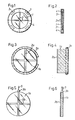
- Figs. 1 and 2 are respectively a plan view and a cross-sectional view of a planar lens provided with an arrangement according to the invention, incorporating a sighting mark in the form of so-called cross hairs and a plurality of light-producing sources of energy making the sighting mark luminous;
- Figs. 3 and 4 are respectively a plan view and a cross-sectional view of a glass body provided with an arrangement according to the invention, having cross hairs on one of its planar end surfaces and supporting a single light-producing source of energy surrounding said glass body within the area of the plane in which the cross hairs are positioned;
- Fig. 1 shows a circular lens or disc 1 of glass or like optical material, said disc incorporates a sighting mark having the form of a cross, so-called cross hairs, 2 which may be scored in the disc material, and four light-producing sources of energy, which preferably are incorporated in said disc and consist each of a small glass capsule containing a 6-radiation active substance and convert the energy of the a-particles into light.
- Miniature radiation sources of this type are available on the market, usually under the designation "beta-light”.
- the ⁇ -ray transmitting substance may be radioactive tritium gas, and for effective transformation of an essential part of the energy into light making the sighting mark luminous, the 8-partic1es have to be decelerated before arriving at the sighting mark proper, and therefore the distance through which the energy is transmitted from the emitting source to the sighting mark, such as through the glass disc, is important, as will be explained below.
- the glass disc 1 may consist of two thin glued- together glass discs with recesses for the light-producing capsules 3 and with the cross hairs 2 scored into either one of the two abutting surfaces.
- the capsules 3 may be incorporated in the glass disc by molding.
- a reflector 4 in the form of a thin rail of U-shaped cross-section is mounted on the periphery of the glass disc, said reflector reflecting light towards the interior of the glass disc.
- the glass disc transmits the light, and the walls of the cross hairs shown will then appear in the form of thin luminous lines of essentially the same fineness as the scored lines constituting the cross hairs.
- 1 and 2 thus is characterised by a number, which could also be one, of very small so-called beta-lights which are disposed within or at least recessed into the glass disc near the periphery thereof and which, by inner reflection from the planar surfaces of the glass disc and from the polished outer edge of said disc, possibly amplified by means of a reflector 4, render the sighting mark, such as aimed cross hairs, luminous.
- the light-producing source consists of a tube 3a curved to circular shape and having a small cross-sectional area.
- the tube encloses a glass disc la which may be in the form of a glass body having a greater axial length than the disc 1 in Figs. 1 and 2.
- the tube 3a contains a radioactive substance transmitting 6-particles.
- the tube 3a is surrounded by a reflector 4a which may have semicircular cross-sectional shape and which tightly encloses the tube 3a.
- the light is generated-by a light-emitting diode 3b tightly connected to the peripheral edge of the glass disc lb, and electric wires 5 and a small battery (not shown).
- the light transmitted through the glass disc lb is internally reflected by the planar sides of the disc and the peripheral surface of the disc and will appear as luminous lines in the cross hair scores 2b.
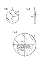
- Figs. 7 and 8 illustrate a variant of the embodiment according to Figs. 5 and 6, and in this variant the sighting mark is not in the form of cross hairs, but in the form of a small dot 2c which is rendered luminous in the same manner as the cross hairs described above, i.e. the dot 2c may consist of a very small cavity in the centre of the glass disc lc, but the dot-shaped sighting mark may also be produced by reflection from a small prism 6 which is formed for example by providing the glass disc on one side with a small recess of triangular or other shape.
- the glass disc shown in Fig. 9 has a sighting mark in the form of cross hairs 2d which, in the embodiment illustrated, are augmented by a dot-shaped central sighting mark I.
- the glass disc ld has, in parallel with the central line of the cross hairs, a number of horizontal lines designated II ... V in Fig. 9 and spaced from the horizontal line of the cross hairs and from one another by distances corresponding to different distances to a target, for example the distance 100 metres for the central line of the cross hairs, 150 metres for the line II, 200 metres for the line III etc.
- these horizontal lines are provided with a number of dots on either side of the vertical line of the cross hairs, such as the dots X, XI, XII. These dots may be used as sighting dots if the firearm, upon use of the dot I or the dots lying on the vertical line of the cross hairs should prove to be aimed incorrectly in the lateral direction.
- Figs. 10 and 11 illustrate an arrangement according to the invention in which the glass disc le is provided with cross hairs 2e and a channel 3e near the periphery of the disc le.
- the cross hairs 2e and the channel 3e may be formed in one or both sides of two glass discs which are then glued together to form communicating channels.
- These channels are filled with, for example, radioactive gas, such as tritium gas, rendering the channels luminous.
- Figs. 12 and 13 illustrate a variant of the embodiment according to Figs. 10 and 11, and in this embodiment the glass disc lf is surrounded by a circularly curved tubular glass capsule 3f containing radioactive tritium gas or some other suitable light-producing substance.
- the channels 2e, 3e and the tube 3f may be provided with a gas-filling device 7.
- the sighting mark may be of different shape, such as dot-shaped, cross-shaped etc., and can be provided in some other manner than by scoring.
- the light can be received and transformed into visible light, for example on the walls defining scored lines or recesses or, according to Figs. 10 and 11, by means of gas-filled luminous channels.
- a sighting mark in the form of, for example, cross hairs can be produced by means of thin wires glued together between two glass discs, for example in the embodiment according to Figs. 5 and 6.
- light-reflecting wires may have the same function as light-reflecting scored lines.
- the thick glass body la illustrated in Fig. 4 may be advantageous in that it changes the angles from the light-producing source towards the scored lines of the cross hairs so that these can be illuminated to a greater or less extent also in the axial direction in order to be more intensely reflected by the side walls of the scored lines.
- the invention also makes it possible to use numbered luminous scales, as in the embodiment shown in Fig. 1, forthe lines II, III etc. and for the dots X, XI etc. Use may also be made of LC technique, in which case a current source may be used for activation.
- a glass capsule 3f which on its inner side, or a part thereof, has a fluorescent coating activated by radioactive tritium gas.
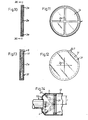
- Fi g. 14 shows a preferred modification wherein the sighting mark is again in the form of so-called cross hairs 2f, but in this modification the cross hairs are freely suspended in the hollow centre of an annular support 11 by being fixed at their four outer ends to the support 11 which, in turn, is fixed to the inner side of a tubular member 12 of the telescopic sighting tube 10.
- An array of beta-lights of the kind described above, for example four beta-lights as in Fig. 1, are fixed in angularly spaced relationship on the inner side of an annular support 11 designed to serve as a reflector.
- the annular reflector 11 is fixed to or formed as a part of the tubular member 12, and unlike the reflector 4 as shown in Fig.
- the reflector 11 supports an array of beta-lights 2f, for example four angularly spaced beta-lights which are coaxial in relation to but axially spaced from the cross hairs support 11 and thus from the sighting mark 2f.
- the radial distance from the capsules 3 to the centre of the sighting mark 2 is approximately lr, where r is the radius of the free light-passage through the annular reflector 4.
- the light from the capsules must travel a distance which will approximately amount to lr, to reach the centre of the sighting mark.
- the ray path in the optical material la is elongated in that scored lines 2a which form the cross hairs, are cut into the glass body or lens la at an axial distance from the plane of the lens where the latter is encircled by the tubular member 3a which contains the a-ray producing substance.
- the path for transforming energy into visible light from the source of energy to the centre of the cross hairs in Fig. 4 is about , which is about 1.4r.
- the distance from the energy producing source such as the beta-capsule 2f in Fig. 14, i.e. the ray path
- the optimal distance appears to be optimally chosen to lie between about 0 and 2r counted from a plane perpendicular to the axis of the instrument 10. or tube 12 through the centre of the sighting mark, e.g. the sighting mark 2f in Fig. 14, and between about lr and 2r counted from the periphery of the light passage opening through the tube 12, i.e. the supporting ring 11, to said centre.
- r is the normal radius of the light opening in the instrument in the plane wherein the sighting mark is disposed, i.e. in the case of Fig. 14 the opening through the supporting ring 11 and in the case of Fig. 1 the lens 1 encircled by the reflector 4.
- the light from the light source is, in the preferred embodiment, substantially or completely transmitted within a body of optical material, usually glass, and is subjected to inner reflection against the sides and edges of the glass body with insignificant radiation loss.
- a body of optical material usually glass
- the transmission path may extend through a gas, such as air, and may be slightly longer within the preferred limits mentioned above, to make the sighting mark luminous, and in this latter case it is preferred to use a sighting mark of thin plastic strips or thin metal wires provided with a highly light-reflecting surface.
Landscapes
- Physics & Mathematics (AREA)
- Optics & Photonics (AREA)
- General Physics & Mathematics (AREA)
- Engineering & Computer Science (AREA)
- General Engineering & Computer Science (AREA)
- Astronomy & Astrophysics (AREA)
- Telescopes (AREA)
- Photometry And Measurement Of Optical Pulse Characteristics (AREA)
- Illuminated Signs And Luminous Advertising (AREA)
Abstract
The invention relates to an arrangement of a sighting mark (2) and a light-producing source of energy (3) therefor in an optical sighting instrument, especially a telescopic sighting tube. The invention is characterised in that at least one light-emitting capsule (3f), preferably at least one β-ray transmissive capsule enclosing a β-ray producing substance, is mounted in the telescopic sighting tube at a point on a circle which is centered on the longitudinal axis of the sighting instrument and disposed at an axial distance of between about 0 and 2 r counted from a plane which is perpendicular to said axis and passes through the centre of the sighting mark (2f), the distance to said centre not exceeding 2 r, where r is the radius from said centre to the periphery of the light opening in the sighting tube (12) at the level of said plane; said capsule (3f), whether it is mounted spaced from or in said plane, being positioned and directed to send at least a substantial proportion of the radiation from the capsule onto the slighting mark to make the latter luminous.
Description
- The present invention relates to an arrangement of a sighting mark, such as cross hairs or the like, and a light-producing source of energy to make the sighting mark luminous.
- In conventional optical sighting instruments of the telescopic sighting tube type, the sighting mark usually is in the form of so-called cross hairs. It is, however, difficult to distinguish the thin lines forming the cross hairs against the background already at twilight, and therefore such sighting marks are no help at all for night shooting.
- In contrast to conventional telescopic sights, so-called luminous spot sights are provided with an arrangement for generating a luminous spot, i.e. a luminous sighting mark, and this known arrangement usually comprises a small electric battery, a light-emitting diode, and a translucent spherical mirror. If the mirror lies in the marksman's field of vision, which it usually does, the light intensity of the luminous spot sight, i.e. the admission of light through the sight from the target to the marksman's eye, is deteriorated to some extent. Using this known arrangement of luminous spot sights in connection with the telescopic sights is difficult, and so far the arrangement could not be successfully applied to telescopic sights, in spite of the fact that the cross hairs of telescopic sights - however great the light- transmitting capacity of these sights may be - frequently are not perceived by the marksman under certain light conditions, such as darkness and dusk, although the actual target area may be well visible.
- It is the object of this invention to overcome the above-mentioned problems by providing, for use in connection with sighting instruments of different types, although especially for telescopic sighting tubes, an arrangement that enables the marksman, with a minimum of trouble, to perceive the sighting mark also in complete darkness.
- To this end, the invention provides an arrangement of a sighting mark and a light-producing source of energy therefor in a sighting instrument, especially a telescopic sighting tube, in order to make the sighting mark luminous, said arrangement being characterised in that at least one light-producing source of energy, especially a a-ray transmissive capsule enclosing a 8-ray producing substance, is mounted in the telescopic sighting tube at a point on a circle centered on the longitudinal axis of the sighting instrument and disposed at an axial distance of between about 0 and 2 r counted from a plane which is perpendicular to said axis and passes through the centre of the sighting mark, where r is the radius from the centre to the periphery of the light opening in the sighting tube at the level of said plane, and in that means are provided to direct radiation from said capsule to the sighting mark.
- In a preferred embodiment according to the invention, use is made of β-ray producing capsules disposed at a distance not exceeding 1 r from the plane of the sighting mark and most preferably 0 r which means that each capsule is incorporated in said plane. In this case, the sighting- mark is formed on or incorporated in a disc of optical material, and by mounting each capsule on the peripheral edge of the disc or incorporating the capsule in the material proper, the material will serve as a light transmitter leading directly to the sighting mark. Such an embodiment will eliminate all of the problems described above and, furthermore, renders disconnection of the source of energy superfluous when a sighting instrument equipped with the arrangement according to the invention is not being used. In this manner, the marksman avoids the vexing consequence of a complete discharge of the battery simply because he forgot to disconnect the battery upon nonuse of the sighting instrument.
- However, the light-producing device may, of course, be a light-emitting diode and an electric miniature battery of the same type as is being used for luminous spot sights, but also in this instance the present invention renders the use of a semispherical mirror for producing the sighting mark superfluous, and although the arrangement in this instance also may require a microswitch for disconnecting the battery, the power supply from the battery may lie at such a low value that a complete battery discharge will take so long that neglecting to disconnect the battery will make no difference, unless the discharge takes months.
- With the arrangement according to the invention, accurate sharpshooting can be carried out under all dusk and darkness conditions during which the target area is at all perceivable, and furthermore the arrangement according to the invention makes it possible to take aim in complete darkness at targets which are not visible but may be perceived in some other manner, for instance by hearing.
- It should be mentioned in particular that the arrangement according to the invention is eminently suitable for, for example, still-hunting fox from ambush on a moonless night, which has hitherto not been possible for this popular hunting form.
- The invention will be described in greater detail below with reference to the accompanying drawings in which
- Figs. 1 and 2 are respectively a plan view and a cross-sectional view of a planar lens provided with an arrangement according to the invention, incorporating a sighting mark in the form of so-called cross hairs and a plurality of light-producing sources of energy making the sighting mark luminous;
- Figs. 3 and 4 are respectively a plan view and a cross-sectional view of a glass body provided with an arrangement according to the invention, having cross hairs on one of its planar end surfaces and supporting a single light-producing source of energy surrounding said glass body within the area of the plane in which the cross hairs are positioned;
- Figs. 5 and 6 are respectively a plan view and a cross-sectional view of a planar glass lens provided with an arrangement according to the invention which, in this instance, comprises cross hairs and a light-emitting diode as well as a reflector;
- Figs. 7 and 8 are respectively a plan view and a cross-sectional view of a modification of the arrangement shown in Figs. 5 and 6;
- Fig. 9 shows a glass lens having cross hairs and a number of horizontal subsidiary lines for shooting over different target distances, and an arrangement according to the invention for illuminating the horizontal lines;
- Figs. 10 and 11 show a modification of the embodiment according to Figs. 1 and 2 or Figs. 3 and 4, Fig. 10 being a section along line X-X in Fig. 11 and Fig. 11 being a section along line XI-XI in Fig. 10;
- Fig. 12 is a plan view of a further modification;
- Fig. 13 is a cross-sectional view of the embodiment shown in Fig. 12; and
- Fig. 14 is a plan view of still another preferred modification.
- Fig. 1 shows a circular lens or
disc 1 of glass or like optical material, said disc incorporates a sighting mark having the form of a cross, so-called cross hairs, 2 which may be scored in the disc material, and four light-producing sources of energy, which preferably are incorporated in said disc and consist each of a small glass capsule containing a 6-radiation active substance and convert the energy of the a-particles into light. Miniature radiation sources of this type are available on the market, usually under the designation "beta-light". - The β-ray transmitting substance may be radioactive tritium gas, and for effective transformation of an essential part of the energy into light making the sighting mark luminous, the 8-partic1es have to be decelerated before arriving at the sighting mark proper, and therefore the distance through which the energy is transmitted from the emitting source to the sighting mark, such as through the glass disc, is important, as will be explained below.
- The
glass disc 1 may consist of two thin glued- together glass discs with recesses for the light-producingcapsules 3 and with the cross hairs 2 scored into either one of the two abutting surfaces. Alternatively, thecapsules 3 may be incorporated in the glass disc by molding. - A
reflector 4 in the form of a thin rail of U-shaped cross-section is mounted on the periphery of the glass disc, said reflector reflecting light towards the interior of the glass disc. The glass disc transmits the light, and the walls of the cross hairs shown will then appear in the form of thin luminous lines of essentially the same fineness as the scored lines constituting the cross hairs. The embodiment as disclosed in Figs. 1 and 2 thus is characterised by a number, which could also be one, of very small so-called beta-lights which are disposed within or at least recessed into the glass disc near the periphery thereof and which, by inner reflection from the planar surfaces of the glass disc and from the polished outer edge of said disc, possibly amplified by means of areflector 4, render the sighting mark, such as aimed cross hairs, luminous. - It should be noted that the sighting marks, such as cross hairs, are shown on an exaggerated scale in Fig. 1 and the following Figures for illustrative purposes only.
- In the embodiment according to Figs. 3 and 4, the light-producing source consists of a tube 3a curved to circular shape and having a small cross-sectional area. The tube encloses a glass disc la which may be in the form of a glass body having a greater axial length than the
disc 1 in Figs. 1 and 2. Like thecapsules 3 in Figs. 1 and 2, the tube 3a contains a radioactive substance transmitting 6-particles. The tube 3a is surrounded by a reflector 4a which may have semicircular cross-sectional shape and which tightly encloses the tube 3a. - In the embodiment according to Figs. 5 and 6, the light is generated-by a light-emitting diode 3b tightly connected to the peripheral edge of the glass disc lb, and electric wires 5 and a small battery (not shown). The light transmitted through the glass disc lb is internally reflected by the planar sides of the disc and the peripheral surface of the disc and will appear as luminous lines in the
cross hair scores 2b. - Figs. 7 and 8 illustrate a variant of the embodiment according to Figs. 5 and 6, and in this variant the sighting mark is not in the form of cross hairs, but in the form of a
small dot 2c which is rendered luminous in the same manner as the cross hairs described above, i.e. thedot 2c may consist of a very small cavity in the centre of the glass disc lc, but the dot-shaped sighting mark may also be produced by reflection from a small prism 6 which is formed for example by providing the glass disc on one side with a small recess of triangular or other shape. - The glass disc shown in Fig. 9 has a sighting mark in the form of
cross hairs 2d which, in the embodiment illustrated, are augmented by a dot-shaped central sighting mark I. The glass disc ld has, in parallel with the central line of the cross hairs, a number of horizontal lines designated II ... V in Fig. 9 and spaced from the horizontal line of the cross hairs and from one another by distances corresponding to different distances to a target, for example the distance 100 metres for the central line of the cross hairs, 150 metres for the line II, 200 metres for the line III etc. In addition, these horizontal lines are provided with a number of dots on either side of the vertical line of the cross hairs, such as the dots X, XI, XII. These dots may be used as sighting dots if the firearm, upon use of the dot I or the dots lying on the vertical line of the cross hairs should prove to be aimed incorrectly in the lateral direction. - All of these lines and dots ld in Fig. 9 can be made luminous by means of a light-producing device of the type mentioned above or described below.
- Figs. 10 and 11 illustrate an arrangement according to the invention in which the glass disc le is provided with
cross hairs 2e and achannel 3e near the periphery of the disc le. Thecross hairs 2e and thechannel 3e may be formed in one or both sides of two glass discs which are then glued together to form communicating channels. These channels are filled with, for example, radioactive gas, such as tritium gas, rendering the channels luminous. - Figs. 12 and 13 illustrate a variant of the embodiment according to Figs. 10 and 11, and in this embodiment the glass disc lf is surrounded by a circularly curved
tubular glass capsule 3f containing radioactive tritium gas or some other suitable light-producing substance. - In the two embodiments as last described, the
channels tube 3f, respectively, may be provided with a gas-filling device 7. - The embodiments described above merely serve to illustrate the invention, and many modifications may occur. The sighting mark may be of different shape, such as dot-shaped, cross-shaped etc., and can be provided in some other manner than by scoring. In order to produce a luminous sighting mark, the light can be received and transformed into visible light, for example on the walls defining scored lines or recesses or, according to Figs. 10 and 11, by means of gas-filled luminous channels. It should be noted, however, that a sighting mark in the form of, for example, cross hairs can be produced by means of thin wires glued together between two glass discs, for example in the embodiment according to Figs. 5 and 6. Thus, light-reflecting wires may have the same function as light-reflecting scored lines.
- The thick glass body la illustrated in Fig. 4 may be advantageous in that it changes the angles from the light-producing source towards the scored lines of the cross hairs so that these can be illuminated to a greater or less extent also in the axial direction in order to be more intensely reflected by the side walls of the scored lines.
- The invention also makes it possible to use numbered luminous scales, as in the embodiment shown in Fig. 1, forthe lines II, III etc. and for the dots X, XI etc. Use may also be made of LC technique, in which case a current source may be used for activation.
- For embodiments similar to the one shown in Figs. 12 and 13, use may be made of a
glass capsule 3f which on its inner side, or a part thereof, has a fluorescent coating activated by radioactive tritium gas. - Fig. 14 shows a preferred modification wherein the sighting mark is again in the form of so-called
cross hairs 2f, but in this modification the cross hairs are freely suspended in the hollow centre of anannular support 11 by being fixed at their four outer ends to thesupport 11 which, in turn, is fixed to the inner side of atubular member 12 of thetelescopic sighting tube 10. An array of beta-lights of the kind described above, for example four beta-lights as in Fig. 1, are fixed in angularly spaced relationship on the inner side of anannular support 11 designed to serve as a reflector. Theannular reflector 11 is fixed to or formed as a part of thetubular member 12, and unlike thereflector 4 as shown in Fig. 1 thereflector 11 supports an array of beta-lights 2f, for example four angularly spaced beta-lights which are coaxial in relation to but axially spaced from thecross hairs support 11 and thus from thesighting mark 2f. In the embodiment shown in Fig. 1, the radial distance from thecapsules 3 to the centre of the sighting mark 2 is approximately lr, where r is the radius of the free light-passage through theannular reflector 4. Thus, the light from the capsules must travel a distance which will approximately amount to lr, to reach the centre of the sighting mark. Experiments have shown that the energy emitted from a so-called beta-light capsule of the standard type available on the market and of a volume suitable to be incorporated peripherally in relation to a sighting mark of the cross hairs type in a telescopic sighting tube of normal dimensions for use on a firearm, will be efficiently transformed into visible light on or in the sighting mark to make it luminous, provided that the travelling distance through most optical materials, for example glass, amounts to at least the distance lr mentioned above. In several cases, r is also equivalent to the radius of a normal sighting mark in the form of cross hairs of the type shown in, for example, Figs. 1 and 14. - In the embodiment shown in Figs. 3 and 4, the ray path in the optical material la is elongated in that scored
lines 2a which form the cross hairs, are cut into the glass body or lens la at an axial distance from the plane of the lens where the latter is encircled by the tubular member 3a which contains the a-ray producing substance. Thus, the path for transforming energy into visible light from the source of energy to the centre of the cross hairs in Fig. 4 is about
capsule 2f in Fig. 14, i.e. the ray path, may be somewhat longer. However, the presentday theory is that the optimal distance appears to be optimally chosen to lie between about 0 and 2r counted from a plane perpendicular to the axis of theinstrument 10. ortube 12 through the centre of the sighting mark, e.g. thesighting mark 2f in Fig. 14, and between about lr and 2r counted from the periphery of the light passage opening through thetube 12, i.e. the supportingring 11, to said centre. As has been mentioned above, r is the normal radius of the light opening in the instrument in the plane wherein the sighting mark is disposed, i.e. in the case of Fig. 14 the opening through the supportingring 11 and in the case of Fig. 1 thelens 1 encircled by thereflector 4. - As will appear from the above description, the light from the light source is, in the preferred embodiment, substantially or completely transmitted within a body of optical material, usually glass, and is subjected to inner reflection against the sides and edges of the glass body with insignificant radiation loss. In this manner, and because the light intensity and energy can be held at very low levels, the light will interfere with the marksman's eye to an insignificant extent only, and the source of energy will obtain long life. However, in another preferred embodiment, shown in Fig. 14, the transmission path may extend through a gas, such as air, and may be slightly longer within the preferred limits mentioned above, to make the sighting mark luminous, and in this latter case it is preferred to use a sighting mark of thin plastic strips or thin metal wires provided with a highly light-reflecting surface.
Claims (12)
1. Arrangement of a sighting mark and a light-producing source of energy therefor in a sighting instrument, especially a telescopic sighting tube, in order to make the sighting mark luminous, characterised in that at least one light-producing source of energy, especially a S-ray transmissive capsule (3) enclosing a a-ray producing substance, is mounted in the telescopic sighting tube at a point on a circle centered on the longitudinal axis of the sighting instrument and disposed at an axial distance of between about 0 and 2r counted from a plane which is perpendicular to said axis and passes through the centre of the sighting mark (2), where r is the radius from the centre to the periphery of the light opening in the sighting tube at the level of said plane, and in that means (4) are provided to direct radiation from said capsule (3) to the sighting mark (2).
2. An arrangement as claimed in claim 1, characterised in that said capsule (3) encloses an element (1) consisting of optical material and supporting said sighting mark (2).
3. An arrangement as claimed in claim 1, characterizedin that said capsule is formed by a cavity (3e) within an element (le) consisting of optical material and supporting said sighting mark (2e).
4. An arrangement as claimed in claim 1, further characterized in that said capsule (3a; 3f) is positioned such that the distance thereof to the centre of said sighting mark does not exceed 2 r.
5. An arrangement as claimed in claim 1, characterized in that said capsule (3) is disposed at a peripheral edge of an element (1) consisting of optical material and supporting said sighting mark (2).
6. An arrangement as claimed in claim 5, characterizedin that it comprises a reflector (4) for reflecting radiation from said a-ray producing substance inwardly into the element (1) consisting of optical material and supporting said sighting mark (2).
7. An arrangement as claimed in claim 1, characterized in that said sighting mark (2a) is supported by a disc of optical material and formed therein by engraving, scoring, recessing or the like and having one or more refractive or reflective peripheries.
8. An arrangement as claimed in claim 1,characterized in that said sighting mark consists of at least one thin element (2f) having at least one light-reflecting surface.
9. An arrangement as claimed in claim 1, characterized in that said sighting mark comprises at least one fine channel (2b) positioned within an element (lb) consisting of optical material, said channel being filled with said 8-ray producing substance, such as radioactive tritium gas.
10. An arrangement as claimed in claim 5, characterized in that said element consisting of optical material is composed of two disc-shaped elements (If) joined together side by side, and that said sighting mark (2e) is formed in that side of one of said disc-shaped elements which faces the other element.
11. An arrangement as claimed in claim 1, characterized in that said sighting mark (2d) is supported by an element (ld) consisting of optical material, and that said element supports, in addition to said sighting mark, markings (II-V) in positions to be made luminous in the same manner as said sighting mark by said a-light producing source, said markings being spaced from said sighting mark (2d) in such a manner that different sighting adjustments of a firearm equipped with said sighting instrument can be selected for corrections, such as correction of lateral errors.
12. A modified arrangement as claimed in claim 1, characterized in that the arrangement has, instead of the said capsule with β-ray producing substance, a light-producing source of energy in the form of a battery-operated miniature light source, such as a small light-emitting diode.
Applications Claiming Priority (2)
| Application Number | Priority Date | Filing Date | Title |
|---|---|---|---|
| SE8404685 | 1984-09-19 | ||
| SE8404685A SE458963B (en) | 1984-09-19 | 1984-09-19 | ARRANGEMENT OF SIGNS AND LIGHT-BEING ENERGY LINKS FOR THE SIGNS |
Publications (2)
| Publication Number | Publication Date |
|---|---|
| EP0179036A2 true EP0179036A2 (en) | 1986-04-23 |
| EP0179036A3 EP0179036A3 (en) | 1988-05-11 |
Family
ID=20357061
Family Applications (1)
| Application Number | Title | Priority Date | Filing Date |
|---|---|---|---|
| EP85850288A Withdrawn EP0179036A3 (en) | 1984-09-19 | 1985-09-18 | Arrangement of a sighting mark and a light-producing source of energy therefor |
Country Status (5)
| Country | Link |
|---|---|
| US (1) | US4743765A (en) |
| EP (1) | EP0179036A3 (en) |
| JP (1) | JPS61124916A (en) |
| KR (1) | KR900000059B1 (en) |
| SE (1) | SE458963B (en) |
Cited By (4)
| Publication number | Priority date | Publication date | Assignee | Title |
|---|---|---|---|---|
| EP0254675A1 (en) * | 1986-07-23 | 1988-01-27 | Leica Aarau AG | Optical sighting device |
| GB2233785A (en) * | 1989-06-30 | 1991-01-16 | Pilkington Perkin Elmer Ltd | Telescopic optical device |
| AT411630B (en) * | 2000-10-17 | 2004-03-25 | Hensoldt & Soehne Optik | ILLUMINATED GRADUATE AND RIFLE SCOPE WITH ILLUMINATED GRADUATE |
| EP3211470A1 (en) * | 2016-02-29 | 2017-08-30 | Swarovski Optik Kg | Device for illuminating a sight |
Families Citing this family (33)
| Publication number | Priority date | Publication date | Assignee | Title |
|---|---|---|---|---|
| SE464104B (en) * | 1989-05-10 | 1991-03-04 | Aimpoint Ab | PARALLAX-FREE AIM |
| US5212590A (en) * | 1989-05-25 | 1993-05-18 | U.S. Philips Corp. | Brightness intensifier tube with alignment marker |
| JPH0329910U (en) * | 1989-07-31 | 1991-03-25 | ||
| US4993819A (en) * | 1989-12-06 | 1991-02-19 | Dba Systems, Inc. | External gunsight eyepiece attachment |
| US5036206A (en) * | 1990-02-12 | 1991-07-30 | Hughes Aircraft Company | Combined laser position detector, infrared emissivity target and TV target |
| US5410106A (en) * | 1991-04-26 | 1995-04-25 | Fujikura Ltd. | Electric feed cable for oil well pump |
| US5442861A (en) * | 1993-12-23 | 1995-08-22 | Lorocco; Paul M. | Sight pin and holder for archery bow |
| JP2899632B2 (en) * | 1994-03-31 | 1999-06-02 | バブコック日立株式会社 | Shooting training equipment |
| US5653034A (en) * | 1995-05-24 | 1997-08-05 | Trijicon, Inc. | Reflex sighting device for day and night sighting |
| US5956854A (en) * | 1996-12-26 | 1999-09-28 | Tru-Glo, Inc. | Day/night weapon sight |
| US5894672A (en) * | 1997-08-14 | 1999-04-20 | Trumark Manufacturing Company | Enhanced sight marker apparatus |
| US5924234A (en) * | 1997-11-20 | 1999-07-20 | Trijicon, Inc. | Optical sighting device |
| US5920995A (en) | 1997-12-08 | 1999-07-13 | Sammut; Dennis J. | Gunsight and reticle therefor |
| US7856750B2 (en) | 1997-12-08 | 2010-12-28 | Horus Vision Llc | Apparatus and method for calculating aiming point information |
| US6802131B1 (en) * | 2002-09-05 | 2004-10-12 | Raytheon Company | Side-illuminated target structure having uniform ring illumination |
| US6807742B2 (en) * | 2002-09-06 | 2004-10-26 | Trijicon, Inc. | Reflex sight with multiple power sources for reticle |
| US8091268B2 (en) | 2006-02-09 | 2012-01-10 | Leupold & Stevens, Inc. | Multi-color reticle for ballistic aiming |
| US7877921B1 (en) | 2006-03-06 | 2011-02-01 | Raytheon Company | Method and apparatus for combining light from two sources to illuminate a reticle |
| US8713845B1 (en) | 2006-08-01 | 2014-05-06 | Raytheon Canada Limited | Method and apparatus for efficiently collecting radiation |
| WO2008049130A2 (en) * | 2006-10-21 | 2008-04-24 | Leupold & Stevens, Inc. | Illumination port for an optical device |
| US7652818B2 (en) * | 2007-02-05 | 2010-01-26 | Raytheon Company | Optical sight having an unpowered reticle illumination source |
| US7876501B2 (en) | 2007-02-05 | 2011-01-25 | Raytheon Company | Optical sight having an unpowered reticle illumination source |
| US7821708B2 (en) * | 2007-10-24 | 2010-10-26 | Raytheon Company | Method and apparatus for illuminating a reticle |
| WO2010132831A1 (en) | 2009-05-15 | 2010-11-18 | Dennis Sammut | Apparatus and method for calculating aiming point information |
| WO2012100015A1 (en) * | 2011-01-19 | 2012-07-26 | Horus Vision Llc | Apparatus and method for calculating aiming point information |
| EP2802837B1 (en) | 2012-01-10 | 2019-03-13 | HVRT Corporation | Apparatus and method for calculating aiming point information |
| EP2943735A4 (en) | 2013-01-11 | 2016-09-21 | Dennis Sammut | Apparatus and method for calculating aiming point information |
| KR101884075B1 (en) * | 2016-09-21 | 2018-07-31 | 국방과학연구소 | Bore sighting system of main gun using light emitting type wire for day and night |
| WO2018057872A1 (en) | 2016-09-22 | 2018-03-29 | Lightforce USA, Inc., d/b/a/ Nightforce Optics, Inc. | Optical targeting information projection system for weapon system aiming scopes and related systems |
| DE102018125142A1 (en) | 2017-10-11 | 2019-04-11 | Sig Sauer, Inc. | BALLISTIC TARGETING SYSTEM WITH DIGITAL REMOVAL |
| KR102015004B1 (en) * | 2017-12-14 | 2019-08-27 | 박광원 | Aligning Apparatus of Gun |
| AU2019388605A1 (en) | 2018-09-04 | 2021-02-18 | Hvrt Corp. | Reticles, methods of use and manufacture |
| WO2021146730A1 (en) | 2020-01-17 | 2021-07-22 | Sig Sauer, Inc. | Telescopic sight having ballistic group storage |
Citations (6)
| Publication number | Priority date | Publication date | Assignee | Title |
|---|---|---|---|---|
| GB133447A (en) * | 1900-01-01 | |||
| US2392979A (en) * | 1942-10-31 | 1946-01-15 | Rca Corp | Luminous reticle |
| US2490091A (en) * | 1945-02-14 | 1949-12-06 | Robert E Reardon | Self-luminous reticle |
| US2527043A (en) * | 1946-05-04 | 1950-10-24 | United States Radium Corp | Optical instrument illumination device |
| CH375928A (en) * | 1959-04-04 | 1964-03-15 | Zeiss Carl Fa | Optical instrument, in particular binoculars |
| GB2068584A (en) * | 1980-01-07 | 1981-08-12 | Arnold & Richter Kg | Reticule For Camera Viewfinder |
Family Cites Families (8)
| Publication number | Priority date | Publication date | Assignee | Title |
|---|---|---|---|---|
| US1529643A (en) * | 1919-07-17 | 1925-03-10 | Fenderl Hektor | Luminous sign, sight, or the like |
| US2162723A (en) * | 1937-10-15 | 1939-06-20 | James C Karnes | Sighting apparatus |
| US2270707A (en) * | 1939-10-18 | 1942-01-20 | John J Humski | Sighting means for firearms |
| US2476390A (en) * | 1947-05-26 | 1949-07-19 | John H Lucas | Post driver |
| US3005102A (en) * | 1957-04-02 | 1961-10-17 | United States Radium Corp | Self luminous lamps |
| US3478209A (en) * | 1965-07-22 | 1969-11-11 | Canrad Precision Ind Inc | Self-luminous tritium light sources |
| US3784817A (en) * | 1971-05-11 | 1974-01-08 | Atlantic Richfield Co | Radio luminescent sighting arrangement |
| SE371491B (en) * | 1973-03-26 | 1974-11-18 | J Ekstrand |
-
1984
- 1984-09-19 SE SE8404685A patent/SE458963B/en not_active IP Right Cessation
-
1985
- 1985-09-18 JP JP60206186A patent/JPS61124916A/en active Pending
- 1985-09-18 EP EP85850288A patent/EP0179036A3/en not_active Withdrawn
- 1985-09-19 KR KR1019850006872A patent/KR900000059B1/en active IP Right Grant
-
1987
- 1987-07-10 US US07/072,156 patent/US4743765A/en not_active Expired - Fee Related
Patent Citations (6)
| Publication number | Priority date | Publication date | Assignee | Title |
|---|---|---|---|---|
| GB133447A (en) * | 1900-01-01 | |||
| US2392979A (en) * | 1942-10-31 | 1946-01-15 | Rca Corp | Luminous reticle |
| US2490091A (en) * | 1945-02-14 | 1949-12-06 | Robert E Reardon | Self-luminous reticle |
| US2527043A (en) * | 1946-05-04 | 1950-10-24 | United States Radium Corp | Optical instrument illumination device |
| CH375928A (en) * | 1959-04-04 | 1964-03-15 | Zeiss Carl Fa | Optical instrument, in particular binoculars |
| GB2068584A (en) * | 1980-01-07 | 1981-08-12 | Arnold & Richter Kg | Reticule For Camera Viewfinder |
Cited By (7)
| Publication number | Priority date | Publication date | Assignee | Title |
|---|---|---|---|---|
| EP0254675A1 (en) * | 1986-07-23 | 1988-01-27 | Leica Aarau AG | Optical sighting device |
| US4877324A (en) * | 1986-07-23 | 1989-10-31 | Kern & Co. Ag | Optical sighting device with illuminated aiming mark |
| GB2233785A (en) * | 1989-06-30 | 1991-01-16 | Pilkington Perkin Elmer Ltd | Telescopic optical device |
| GB2233785B (en) * | 1989-06-30 | 1993-12-08 | Pilkington Perkin Elmer Ltd | Telescopic optical device |
| AT411630B (en) * | 2000-10-17 | 2004-03-25 | Hensoldt & Soehne Optik | ILLUMINATED GRADUATE AND RIFLE SCOPE WITH ILLUMINATED GRADUATE |
| EP3211470A1 (en) * | 2016-02-29 | 2017-08-30 | Swarovski Optik Kg | Device for illuminating a sight |
| US10222628B2 (en) | 2016-02-29 | 2019-03-05 | Swarovski-Optik Kg. | Device for displaying a target mark |
Also Published As
| Publication number | Publication date |
|---|---|
| US4743765A (en) | 1988-05-10 |
| SE8404685L (en) | 1986-03-20 |
| KR860002726A (en) | 1986-04-28 |
| KR900000059B1 (en) | 1990-01-19 |
| SE8404685D0 (en) | 1984-09-19 |
| EP0179036A3 (en) | 1988-05-11 |
| SE458963B (en) | 1989-05-22 |
| JPS61124916A (en) | 1986-06-12 |
Similar Documents
| Publication | Publication Date | Title |
|---|---|---|
| EP0179036A2 (en) | Arrangement of a sighting mark and a light-producing source of energy therefor | |
| US3942901A (en) | Optical sighting instrument with means for producing a sighting mark | |
| EP0128753B1 (en) | An aiming apparatus for a weapon | |
| US5189555A (en) | Parallax free optical sighting device | |
| US7627976B1 (en) | Fiber optic sight for firearms with nighttime capabilities | |
| US6571482B1 (en) | Sighting device for projectile type weapons for operation in day and night | |
| RU2547648C2 (en) | Finder system | |
| US4281366A (en) | Lighting systems for surgical operations | |
| US4559583A (en) | Greeting card with blinking light apparatus | |
| US20110199677A1 (en) | Optical sight | |
| US7355790B1 (en) | Optical sight having a reticle illuminated through a non-lambertian light diffuser | |
| JPH033206B2 (en) | ||
| EP1787082A1 (en) | Retro-reflective aiming means | |
| JP5677443B2 (en) | Luminaire with light guide and Cartesian lens or Cartesian reflector | |
| JP2005508522A (en) | Irradiation type reticle | |
| EP0069575A2 (en) | Improved collimator gun sight | |
| US4390276A (en) | Collimator gunsight | |
| JPH0756088A (en) | Optical device of gunsight without parallax | |
| US4030839A (en) | Frequency selective reflex sight | |
| EP0097449A1 (en) | Vehicle lamp assembly | |
| CN100564997C (en) | Lighting device | |
| GB2049118A (en) | Improved collimator gun sight | |
| US20020080480A1 (en) | Illuminated crosshair plate, and telescopic sight with illuminated crosshair plate | |
| EP1350072B1 (en) | Optical sight | |
| US9194657B1 (en) | Lens for sighting device |
Legal Events
| Date | Code | Title | Description |
|---|---|---|---|
| PUAI | Public reference made under article 153(3) epc to a published international application that has entered the european phase |
Free format text: ORIGINAL CODE: 0009012 |
|
| AK | Designated contracting states |
Kind code of ref document: A2 Designated state(s): AT BE CH DE FR LI |
|
| PUAL | Search report despatched |
Free format text: ORIGINAL CODE: 0009013 |
|
| AK | Designated contracting states |
Kind code of ref document: A3 Designated state(s): AT BE CH DE FR LI |
|
| STAA | Information on the status of an ep patent application or granted ep patent |
Free format text: STATUS: THE APPLICATION IS DEEMED TO BE WITHDRAWN |
|
| 18D | Application deemed to be withdrawn |
Effective date: 19881112 |
|
| RIN1 | Information on inventor provided before grant (corrected) |
Inventor name: EKSTRAND, JOHN ARNE INGEMUND |