EP0164220B1 - Squeeze film damper - Google Patents
Squeeze film damper Download PDFInfo
- Publication number
- EP0164220B1 EP0164220B1 EP85303245A EP85303245A EP0164220B1 EP 0164220 B1 EP0164220 B1 EP 0164220B1 EP 85303245 A EP85303245 A EP 85303245A EP 85303245 A EP85303245 A EP 85303245A EP 0164220 B1 EP0164220 B1 EP 0164220B1
- Authority
- EP
- European Patent Office
- Prior art keywords
- rotor
- squeeze film
- damper
- film damper
- plain
- Prior art date
- Legal status (The legal status is an assumption and is not a legal conclusion. Google has not performed a legal analysis and makes no representation as to the accuracy of the status listed.)
- Expired
Links
Images

Classifications
-
- F—MECHANICAL ENGINEERING; LIGHTING; HEATING; WEAPONS; BLASTING
- F01—MACHINES OR ENGINES IN GENERAL; ENGINE PLANTS IN GENERAL; STEAM ENGINES
- F01D—NON-POSITIVE DISPLACEMENT MACHINES OR ENGINES, e.g. STEAM TURBINES
- F01D25/00—Component parts, details, or accessories, not provided for in, or of interest apart from, other groups
- F01D25/16—Arrangement of bearings; Supporting or mounting bearings in casings
- F01D25/162—Bearing supports
- F01D25/164—Flexible supports; Vibration damping means associated with the bearing
-
- F—MECHANICAL ENGINEERING; LIGHTING; HEATING; WEAPONS; BLASTING
- F16—ENGINEERING ELEMENTS AND UNITS; GENERAL MEASURES FOR PRODUCING AND MAINTAINING EFFECTIVE FUNCTIONING OF MACHINES OR INSTALLATIONS; THERMAL INSULATION IN GENERAL
- F16C—SHAFTS; FLEXIBLE SHAFTS; ELEMENTS OR CRANKSHAFT MECHANISMS; ROTARY BODIES OTHER THAN GEARING ELEMENTS; BEARINGS
- F16C27/00—Elastic or yielding bearings or bearing supports, for exclusively rotary movement
- F16C27/04—Ball or roller bearings, e.g. with resilient rolling bodies
- F16C27/045—Ball or roller bearings, e.g. with resilient rolling bodies with a fluid film, e.g. squeeze film damping
-
- F—MECHANICAL ENGINEERING; LIGHTING; HEATING; WEAPONS; BLASTING
- F16—ENGINEERING ELEMENTS AND UNITS; GENERAL MEASURES FOR PRODUCING AND MAINTAINING EFFECTIVE FUNCTIONING OF MACHINES OR INSTALLATIONS; THERMAL INSULATION IN GENERAL
- F16C—SHAFTS; FLEXIBLE SHAFTS; ELEMENTS OR CRANKSHAFT MECHANISMS; ROTARY BODIES OTHER THAN GEARING ELEMENTS; BEARINGS
- F16C19/00—Bearings with rolling contact, for exclusively rotary movement
- F16C19/02—Bearings with rolling contact, for exclusively rotary movement with bearing balls essentially of the same size in one or more circular rows
- F16C19/04—Bearings with rolling contact, for exclusively rotary movement with bearing balls essentially of the same size in one or more circular rows for radial load mainly
- F16C19/06—Bearings with rolling contact, for exclusively rotary movement with bearing balls essentially of the same size in one or more circular rows for radial load mainly with a single row or balls
-
- F—MECHANICAL ENGINEERING; LIGHTING; HEATING; WEAPONS; BLASTING
- F16—ENGINEERING ELEMENTS AND UNITS; GENERAL MEASURES FOR PRODUCING AND MAINTAINING EFFECTIVE FUNCTIONING OF MACHINES OR INSTALLATIONS; THERMAL INSULATION IN GENERAL
- F16C—SHAFTS; FLEXIBLE SHAFTS; ELEMENTS OR CRANKSHAFT MECHANISMS; ROTARY BODIES OTHER THAN GEARING ELEMENTS; BEARINGS
- F16C2360/00—Engines or pumps
- F16C2360/23—Gas turbine engines
Definitions
- This invention relates, generally, to squeeze film dampers for controlling rotor vibrations and, more particularly, to a squeeze film damper as specified in the preamble of claim 1, for example, as disclosed in US-A-4,337,983.
- a squeeze film damper according to the present invention is characterised by the features specified in the characterising portion of claim 1.
- a squeeze film damper according to this invention represents an improvement over known plain squeeze film dampers and exhibits a substantially linear or constant damping coefficient characteristic for vibratory radial displacement of the rotor up to substantially the entire available clearance.
- this invention is a new and improved squeeze film damper for controlling vibration of a dynamically unbalanced rotor.
- a feature of this invention resides in the provision in the new and improved damper of a small annulus having a radial depth corresponding to maximum radial vibratory displacement of the rotor and a large annulus having a radial depth corresponding to optimum damping at maximum radial displacement, the small annulus limiting static rotor displacement to minimize engine clearance and the large annulus providing effectively linear damping coefficient at radial displacements up to the depth of the small annulus.
- Another feature of this invention resides in the provision in the new and improved damper of a small annulus formed between a pair of plain cylindrical surfaces, one of which is fixed and the other of which vibrates with the rotor, and in the provision of a groove in the fixed surface extending over between and ⁇ of the length of the small annulus and defining with the other plain surface a large annulus centred lengthwise of the small annulus having a radial depth at least three times the radial depth of the small annulus.
- the small annulus is defined between an outer plain cylindrical surface on an outer bearing race vibrateable with the rotor and an internal plain cylindrical surface on a support concentric with the outer cylindrical surface, the internal plain cylindrical surface having a rectangular shaped groove therein defining the radially outer portion of the large annulus of the damper.
- the engine 10 includes an engine housing block 12 to which is attached a generally cylindrical plenum cover 14 defining therein an air plenum 16 supplied with pressurized air from a compressor, not shown, of the engine.
- the products of combustion exhausted through outlet 22 are directed through a plurality of vanes 23 in a nozzle ring 24 supported on the engine housing block 12 at the upstream end of an annular flow path 26 along which the products of combustion move.
- a plurality of partially illustrated spokes 27 forming a rigid part of the engine housing block 12 project radially inboard of the outlet 22 and the annular flow path 26 and rigidly support therewithin a web portion 28 of the engine block.
- the web portion has a generally cylindrical flange 30 with a bore 31 therein and a radial flange 32 with a circular aperture 34 therein, the aperture 34 and the bore 31 in the flange 30 being centred or aligned on a nominal rotation axis 36 of the engine.
- a gasifier rotor 38 of the engine has a turbine end 40 and a compressor end, not shown, interconnected by a shaft 42 nominally aligned on the axis 36.
- the turbine end 40 includes a wheel 44 integral with the shaft 42 having a plurality of blades 46 disposed circumferentially therearound in the motive fluid flow path 26 downstream of the nozzle ring 24.
- a shroud ring 48 mounted on the engine block is closely fitted around the tips of the blades 46.
- Motive fluid is directed by the nozzle vanes 23 against the turbine blades 46 to rotate the wheel 44 and the rotor 38 and then proceeds down the flow path 26 for further redirection and expansion through subsequent turbine blade stages, not shown, of the power turbines of the engine.
- the turbine wheel 44 has an integral stub shaft 52 nominally aligned on axis 36 and projecting toward the combustor 18.
- a sleeve 54 is received around the stub shaft 52 and abuts the turbine wheel 44.
- a plurality of circular knife edges 56 on the sleeve 54 radially inboard of the circular aperture 34 in the web portion 28 co-operate with a seal 58 on the radial flange 32 in defining a conventional labyrinth seal in the aperture 34.
- a bearing 59 has a cylindrical inner race 60 received around the sleeve 54 with a shield ring 62 captured between the inner race and a shoulder 64 on the sleeve 54.
- the inner race 60 and the shield ring 62 are tightly captured between the shoulder 64 and a retainer 66 on the outboard end of stub shaft 52, the retainer 66 also functioning to tightly press the sleeve 54 against the turbine wheel 44 so that the inner race 60, the shield 62 and the sleeve 54 are all rotatable as a unit with the gasifier rotor 38.
- the bearing 59 further includes a plurality of ball type anti-friction elements 68 which roll in a groove 70 in the inner race 60 and a corresponding groove 72 in a cylindrical outer race 74 of the bearing.
- the bearing 59 is of sufficient precision that the inner race 60 is freely rotatable relative to the outer race 74with substantially no clearance or play perpendicular to the axis 36 so that the outer race 74 vibrates as a unit with the rotor 38.
- the outer race 74 has a first lateral face 76, a second lateral face 78, and an outer plain cylindrical surface 80 therebetween.
- a generally cylindrical damper sleeve 82 has an outside diameter 84 corresponding to the diameter of bore 31 in the cylindrical flange 30 on web portion 28 of the engine block.
- the damper sleeve is received in the bore 31 and abuts a shoulder 86 on the flange with a key, not, shown, preventing rotation of the sleeve in the bore.
- the outer race 74 of the bearing is, in turn, received within the damper sleeve with the first lateral face 76 abutting a shoulder 87 of the damper sleeve.
- a flat ring 88 oriented in a transverse plane perpendicular to axis 36 is closely received within the bore 31 of the cylindrical flange 30 and abuts the outboard end of the damper sleeve and the second lateral face 78 of the outer race 74.
- the flat ring 88 is held in position, capturing the damper sleeve 82 and the outer race 74 of the bearing 59, by a retainer 90 seated in an appropriate groove in the cylindrical flange 30.
- An integral lubrication spigot 92 on the damper sleeve 82 has an internal bore 94 in communication with an external groove 95 in the damper sleeve which, in turn, is open to a lubricant supply conduit 96 of the engine whereby lubricating fluid is pumped from the conduit 96 through a nozzle 98 in the spigot onto the rolling elements 68 of the bearing 59.
- the outer race 74 of the bearing is keyed or otherwise connected to the damper sleeve 82 in a manner which prevents relative rotation between the damper sleeve and the outer race but which allows the outer race to vibratorily orbit or translate within the damper sleeve.
- a squeeze film damper 100 is defined between the bearing outer race 74 and the damper sleeve 82 to damp vibrations of the rotor 38-at the turbine end 40.
- the damper includes the plain outer cylindrical surface 80 of the bearing outer race and a plain inner cylindrical surface 102 formed on the damper sleeve 82 in surrounding relation to the outer surface 80 of the race 74.
- the radial depth of the small annulus 104 is the clearance between the bearing outer race 74 and the damper sleeve 82 and represents the maximum permissible vibratory radial displacement of the stub shaft 52 at the turbine end from the axis 36.
- the axial length of the small annulus 104 designated L in Figure 3, is the axial length of the damper 100 and corresponds to the distance over which the plain inner and outer surfaces 102 and 80, respectively, remain concentric and does not include, for example, the outermost extremities where the outer surface 80 on the bearing outer race 74 merges with a pair of radiused corners 105, Figure 2, between the lateral faces 76 and 78 and outer surface 80.
- the squeeze film damper 100 further includes a step in the plain inner surface 102 in the form of a groove 106 in the damper sleeve 82 opening through the plain inner surface 102.
- the groove 106 is rectangular in longitudinal cross section, Figures 2 and 3, and includes a pair of opposite sides 108 and 110 and a plain cylindrical base 112.
- the sides 108 and 110 are symmetrical with respect to a transverse plane 114 perpendicular to axis 36 midway between the ends of the small annulus 104 so that the groove 106 divides the small annulus into a pair of identical halves of lengths L s , Figure 3, separated by the groove 106.
- the base 112 is concentric with the inner plain surface 102 and is located at a radial distance from the axis 36 which exceeds the radial distance from the axis to the inner plain surface 102 so that, when the stub shaft 52 is precisely aligned on axis 36, the base 112 co-operates with the outer plain surfaces 80 on the bearing race in defining an outer, large annulus 116 having a radial depth B, Figure 3.
- the large annulus 116 communicates with the external groove 95 in the damper sleeve 82 through a passage 118 so that, during engine operation, the large and small annuli are filled with hydraulic fluid. While illustrated as being formed in the inner surface 102, the groove 106 could, alternatively, be formed in the outer surface 80 without altering the characteristics of the squeeze film damper 100.
- the squeeze film damper 100 is an improvement over plain squeeze film dampers of comparable capacity. More particularly, when the rotor 38 is at rest or rotating below damper lift-off speed, gravity draws the stub shaft 52 down until the bearing outer plain surface 80 rests on the separated halves of the inner surface 102 at points directly below axis 36. The small and large annuli 104 and 116, respectively, are thus locally constricted below the axis 36, Figure 4. The centre of the stub shaft 52, designated 120 in Figure 4, is likewise displaced radially downward a distance corresponding to the radial depth A of the small annulus 104 as are the rotor extremities such as the knife edges 56 and the tips of the turbine blades 46.
- the outer plain surface 80 on the bearing outer race 74 lifts off from the separated halves of the inner plain surface 102. Lift-off occurs when the magnitude of the rotor dynamic unbalance force vector, not shown, exceeds the weight of the rotor whereupon the centre 120 of the stub shaft commences to orbit in a circle 122, Figure 4, around the axis 36 while the outer race 74 concurrently orbits in a circle around the axis 36 without rotation relative to the damper sleeve 82.
- the radius of the circle 122 is the radial vibratory displacement of the stub shaft 52 and has a maximum value corresponding to the radial depth A of the small annulus 104.
- the resultant force vector F includes a direct component F o generally tangent to the inner and outer plain surfaces 102 and 80, respectively, at the local constriction of the small and large annuli 104 and 116, respectively, and an indirect component F, perpendicular to the direct component.
- the direct component resists orbital translation of the bearing outer race 74 and provides direct damping while the indirect component F, resists radial displacement of the bearing outer race and provides indirect damping.
- the magnitudes of the direct and indirect components are related to the speed and vibratory displacement of the rotor by proportionality factors known as coefficients of direct and indirect damping, C D and C,, respectively.
- C D and C are constant regardless of actual vibratory radial displacement.
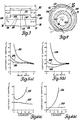
- a pair of curves 124 and 126 illustrate the actual relationships for a typical plain squeeze film damper between C D and C,, respectively, and vibratory radial displacement expressed as a ratio of actual displacement to total clearance or total available displacement.
- Curve 124 shows that C o is somewhat linear or constant over only a small range where actual displacement is about 30 to 50 percent of available clearance and C, is effectively non-linear over the full range of displacement.
- a corresponding pair of curves 128 and 130 Figures 6(a) and 6(b), respectively, illustrate the same relationship for the damper 100 according to this invention. Both C o and C, for the damper 100 are substantially constant over the full range of rotor displacement.
- a curve 132, Figure 5(a) illustrates the relationship between C D and R where the vibratory radial displacement of the rotor is 80% of maximum and a pair of curves 134 and 136 illustrate the same relationship where displacement is 50% and 20% of maximum, respectively.
- R is less than 2
- C o is non-linear and where R exceeds 2
- C D is substantially constant or linear.
- a plurality of curves 138, 140 and 142 relate C, and R for radial displacement of 80%, 50% and 20% of maximum, respectively, and show that C, is linear where R exceeds 2 and is non-linear where R is less than 2. Accordingly, since linear coefficients of damping are desirable, the radial depth B of large annulus 116 must be of the order of at least three times the radial depth of the small annulus.
- the length of the groove 106 is related to the length L of the damper 100 in the sense that as L G decreases, the characteristics of the damper 100 approach those of a plain damper having a radial depth equal to the radial depth A of the small annulus 104 and as L G increases and L s on opposite sides of the groove decreases, the fluid seal effect of the separated halves of the small annulus 104 decreases thereby permitting the fluid pressure in the large annuli 116 to decrease and degrading the direct and indirect damping performance of the damper.
- the length L G of groove 106 is ideally limited to a range of between 2 and of the length L of the damper.
Landscapes
- Engineering & Computer Science (AREA)
- General Engineering & Computer Science (AREA)
- Mechanical Engineering (AREA)
- Support Of The Bearing (AREA)
Description
- This invention relates, generally, to squeeze film dampers for controlling rotor vibrations and, more particularly, to a squeeze film damper as specified in the preamble of
claim 1, for example, as disclosed in US-A-4,337,983. - In high speed rotor applications, such as gasifier rotors in gas turbine engines, dynamic unbalance generates vibrations during rotor rotation which are commonly controlled or damped by squeeze film type dampers. In typical, plain squeeze film dampers where oil filled annuli are formed between stationary plain cylindrical surfaces and plain cylindrical surfaces vibrating with the rotors, coefficients of damping are relatively constant for vibratory radial displacements up to about 50% of the available clearance or depth of the squeeze film annuli. Beyond 50% displacement, the coefficients of damping in plain dampers become non-linear and the dampers become objectionably stiff. Thus, as a practical matter, 50% of the available clearance in plain squeeze film dampers is unproductive in the sense of providing damping and counterproductive in the sense that corresponding clearances are required within the engine between the rotor and surrounding stationary components such as seals. To minimize internal engine clearances, some plain dampers incorporate springs which centre the rotor when the latter is stopped or rotating below damper lift-off speed and some plain dampers are teamed with external snubbers which physically limit the amount of radial displacement of the rotor. These proposals, however, are complex, expensive, and consume valuable space in the engine.
- A squeeze film damper according to the present invention is characterised by the features specified in the characterising portion of
claim 1. - A squeeze film damper according to this invention represents an improvement over known plain squeeze film dampers and exhibits a substantially linear or constant damping coefficient characteristic for vibratory radial displacement of the rotor up to substantially the entire available clearance.
- Accordingly, this invention is a new and improved squeeze film damper for controlling vibration of a dynamically unbalanced rotor. A feature of this invention resides in the provision in the new and improved damper of a small annulus having a radial depth corresponding to maximum radial vibratory displacement of the rotor and a large annulus having a radial depth corresponding to optimum damping at maximum radial displacement, the small annulus limiting static rotor displacement to minimize engine clearance and the large annulus providing effectively linear damping coefficient at radial displacements up to the depth of the small annulus. Another feature of this invention resides in the provision in the new and improved damper of a small annulus formed between a pair of plain cylindrical surfaces, one of which is fixed and the other of which vibrates with the rotor, and in the provision of a groove in the fixed surface extending over between and § of the length of the small annulus and defining with the other plain surface a large annulus centred lengthwise of the small annulus having a radial depth at least three times the radial depth of the small annulus. In a preferred embodiment of this invention, the small annulus is defined between an outer plain cylindrical surface on an outer bearing race vibrateable with the rotor and an internal plain cylindrical surface on a support concentric with the outer cylindrical surface, the internal plain cylindrical surface having a rectangular shaped groove therein defining the radially outer portion of the large annulus of the damper.
- These and other features of this invention will be readily apparent from the following specification and from the accompanying drawings, in which:
- Figure 1 is a partially broken-away elevational view of a portion of a gas turbine engine incorporating a squeeze film damper according to this invention;
- Figure 2 is an enlarged view of a portion of Figure 1 showing the squeeze film damper according to this invention;
- Figure.3 is an enlarged schematic longitudinal cross-section of the squeeze film damper according to this invention;
- Figure 4 is a schematic transverse cross-section of the squeeze film damper according to this invention;
- Figures 5(a) and 5(b) are graphic representations of the relationships between damper relief ratio and direct and indirect damping coefficients at various rotor displacements for the squeeze film damper according to this invention; and
- Figures 6(a) and 6(b) are graphic representations of the relationships between rotor displacement and direct and indirect damping coefficients for the squeeze film damper according to this invention.
- Referring now to Figure 1 of the drawings, a portion of a hot section of an axial flow gas turbine engine 10 is illustrated in fragmentary elevational view. The engine 10 includes an
engine housing block 12 to which is attached a generally cylindrical plenum cover 14 defining therein anair plenum 16 supplied with pressurized air from a compressor, not shown, of the engine. A generallycylindrical combustor 18, defining acombustion chamber 20 with anannular outlet 22, is disposed within theplenum 16. Pressurized air in theplenum 16 enters thecombustion chamber 20 through the walls of the combustor and supports combustion therein of fuel dispersed from the opposite end of the combustor, the products of combustion being directed out of the combustion chamber through theannular outlet 22. The products of combustion exhausted throughoutlet 22 are directed through a plurality ofvanes 23 in anozzle ring 24 supported on theengine housing block 12 at the upstream end of anannular flow path 26 along which the products of combustion move. A plurality of partially illustratedspokes 27 forming a rigid part of theengine housing block 12 project radially inboard of theoutlet 22 and theannular flow path 26 and rigidly support therewithin aweb portion 28 of the engine block. The web portion has a generallycylindrical flange 30 with abore 31 therein and aradial flange 32 with a circular aperture 34 therein, the aperture 34 and thebore 31 in theflange 30 being centred or aligned on anominal rotation axis 36 of the engine. - A
gasifier rotor 38 of the engine has aturbine end 40 and a compressor end, not shown, interconnected by ashaft 42 nominally aligned on theaxis 36. Theturbine end 40 includes a wheel 44 integral with theshaft 42 having a plurality ofblades 46 disposed circumferentially therearound in the motivefluid flow path 26 downstream of thenozzle ring 24. Ashroud ring 48 mounted on the engine block is closely fitted around the tips of theblades 46. Motive fluid is directed by the nozzle vanes 23 against theturbine blades 46 to rotate the wheel 44 and therotor 38 and then proceeds down theflow path 26 for further redirection and expansion through subsequent turbine blade stages, not shown, of the power turbines of the engine. - As seen best in Figures 1 and 2, the turbine wheel 44 has an
integral stub shaft 52 nominally aligned onaxis 36 and projecting toward thecombustor 18. Asleeve 54 is received around thestub shaft 52 and abuts the turbine wheel 44. A plurality ofcircular knife edges 56 on thesleeve 54 radially inboard of the circular aperture 34 in theweb portion 28 co-operate with aseal 58 on theradial flange 32 in defining a conventional labyrinth seal in the aperture 34. Abearing 59 has a cylindrical inner race 60 received around thesleeve 54 with ashield ring 62 captured between the inner race and a shoulder 64 on thesleeve 54. The inner race 60 and theshield ring 62 are tightly captured between the shoulder 64 and aretainer 66 on the outboard end ofstub shaft 52, theretainer 66 also functioning to tightly press thesleeve 54 against the turbine wheel 44 so that the inner race 60, theshield 62 and thesleeve 54 are all rotatable as a unit with thegasifier rotor 38. - The
bearing 59 further includes a plurality of ball typeanti-friction elements 68 which roll in a groove 70 in the inner race 60 and a corresponding groove 72 in a cylindricalouter race 74 of the bearing. Thebearing 59 is of sufficient precision that the inner race 60 is freely rotatable relative to the outer race 74with substantially no clearance or play perpendicular to theaxis 36 so that theouter race 74 vibrates as a unit with therotor 38. Theouter race 74 has a firstlateral face 76, a secondlateral face 78, and an outer plaincylindrical surface 80 therebetween. - As seen best in Figure 2, a generally
cylindrical damper sleeve 82 has an outside diameter 84 corresponding to the diameter ofbore 31 in thecylindrical flange 30 onweb portion 28 of the engine block. The damper sleeve is received in thebore 31 and abuts ashoulder 86 on the flange with a key, not, shown, preventing rotation of the sleeve in the bore. Theouter race 74 of the bearing is, in turn, received within the damper sleeve with the firstlateral face 76 abutting ashoulder 87 of the damper sleeve. Aflat ring 88 oriented in a transverse plane perpendicular toaxis 36 is closely received within thebore 31 of thecylindrical flange 30 and abuts the outboard end of the damper sleeve and the secondlateral face 78 of theouter race 74. Theflat ring 88 is held in position, capturing thedamper sleeve 82 and theouter race 74 of thebearing 59, by aretainer 90 seated in an appropriate groove in thecylindrical flange 30. Anintegral lubrication spigot 92 on thedamper sleeve 82 has an internal bore 94 in communication with anexternal groove 95 in the damper sleeve which, in turn, is open to alubricant supply conduit 96 of the engine whereby lubricating fluid is pumped from theconduit 96 through anozzle 98 in the spigot onto therolling elements 68 of thebearing 59. Theouter race 74 of the bearing is keyed or otherwise connected to thedamper sleeve 82 in a manner which prevents relative rotation between the damper sleeve and the outer race but which allows the outer race to vibratorily orbit or translate within the damper sleeve. - Referring particularly to Figures 2, 3 and 4, a
squeeze film damper 100 according to this invention is defined between the bearingouter race 74 and thedamper sleeve 82 to damp vibrations of the rotor 38-at theturbine end 40. The damper includes the plain outercylindrical surface 80 of the bearing outer race and a plain innercylindrical surface 102 formed on thedamper sleeve 82 in surrounding relation to theouter surface 80 of therace 74. When thestub shaft 52 of the rotor is precisely aligned on nominalrotational axis 36 of the engine, the inner andouter surfaces small annulus 104. The radial depth of thesmall annulus 104, designated A in Figure 3 and exaggerated for clarity, is the clearance between the bearingouter race 74 and thedamper sleeve 82 and represents the maximum permissible vibratory radial displacement of thestub shaft 52 at the turbine end from theaxis 36. The axial length of thesmall annulus 104, designated L in Figure 3, is the axial length of thedamper 100 and corresponds to the distance over which the plain inner andouter surfaces outer surface 80 on the bearingouter race 74 merges with a pair ofradiused corners 105, Figure 2, between thelateral faces outer surface 80. - The
squeeze film damper 100 further includes a step in the plaininner surface 102 in the form of agroove 106 in thedamper sleeve 82 opening through the plaininner surface 102. Thegroove 106 is rectangular in longitudinal cross section, Figures 2 and 3, and includes a pair ofopposite sides cylindrical base 112. Thesides axis 36 midway between the ends of thesmall annulus 104 so that thegroove 106 divides the small annulus into a pair of identical halves of lengths Ls, Figure 3, separated by thegroove 106. Thebase 112 is concentric with theinner plain surface 102 and is located at a radial distance from theaxis 36 which exceeds the radial distance from the axis to theinner plain surface 102 so that, when thestub shaft 52 is precisely aligned onaxis 36, thebase 112 co-operates with theouter plain surfaces 80 on the bearing race in defining an outer, large annulus 116 having a radial depth B, Figure 3. The large annulus 116 communicates with theexternal groove 95 in thedamper sleeve 82 through a passage 118 so that, during engine operation, the large and small annuli are filled with hydraulic fluid. While illustrated as being formed in theinner surface 102, thegroove 106 could, alternatively, be formed in theouter surface 80 without altering the characteristics of thesqueeze film damper 100. - In operation, the
squeeze film damper 100 according to this invention is an improvement over plain squeeze film dampers of comparable capacity. More particularly, when therotor 38 is at rest or rotating below damper lift-off speed, gravity draws thestub shaft 52 down until the bearingouter plain surface 80 rests on the separated halves of theinner surface 102 at points directly belowaxis 36. The small andlarge annuli 104 and 116, respectively, are thus locally constricted below theaxis 36, Figure 4. The centre of thestub shaft 52, designated 120 in Figure 4, is likewise displaced radially downward a distance corresponding to the radial depth A of thesmall annulus 104 as are the rotor extremities such as theknife edges 56 and the tips of theturbine blades 46. Around the rotor within the engine, then, a clearance equal to the radial depth A must be maintained. However, because the radial depth A is generally equal to the maximum radial vibratory displacement of the rotor, the required clearance is the minimum possible clearance for the rotor and, therefore, represents no sacrifice of engine efficiency as does the excess clearance which is a necessary part of heretofore known plain squeeze film dampers. - As the speed of the
rotor 38 increases, the outerplain surface 80 on the bearingouter race 74 lifts off from the separated halves of the innerplain surface 102. Lift-off occurs when the magnitude of the rotor dynamic unbalance force vector, not shown, exceeds the weight of the rotor whereupon thecentre 120 of the stub shaft commences to orbit in a circle 122, Figure 4, around theaxis 36 while theouter race 74 concurrently orbits in a circle around theaxis 36 without rotation relative to thedamper sleeve 82. The radius of the circle 122 is the radial vibratory displacement of thestub shaft 52 and has a maximum value corresponding to the radial depth A of thesmall annulus 104. Assuming maximum radial displacement, the accompanying localized constriction of the small and large annuli orbits around theaxis 36 at the speed of the rotor, pushing fluid ahead of it, and developing a force vector F, Figure 4, resisting or damping vibratory displacement of the stub shaft and the bearing outer race. The damping force vector F is developed primarily in the large annulus 116 which, because its radial depth B substantially exceeds the radial displacement A, exhibits characteristics similar to characteristics exhibited by an ordinary plain squeeze film damper for vibratory displacements in the range of about 50% of available clearance. - With respect, now, to the performance of the
squeeze film damper 100 according to this invention, the resultant force vector F includes a direct component Fo generally tangent to the inner and outerplain surfaces large annuli 104 and 116, respectively, and an indirect component F, perpendicular to the direct component. The direct component resists orbital translation of the bearingouter race 74 and provides direct damping while the indirect component F, resists radial displacement of the bearing outer race and provides indirect damping. The magnitudes of the direct and indirect components are related to the speed and vibratory displacement of the rotor by proportionality factors known as coefficients of direct and indirect damping, CD and C,, respectively. Ideally, CD and C, are constant regardless of actual vibratory radial displacement. In Figures 6(a) and 6(b), however, a pair ofcurves Curve 124 shows that Co is somewhat linear or constant over only a small range where actual displacement is about 30 to 50 percent of available clearance and C, is effectively non-linear over the full range of displacement. By comparison, a corresponding pair ofcurves damper 100 according to this invention. Both Co and C, for thedamper 100 are substantially constant over the full range of rotor displacement. - In the
damper 100 according to this invention, Co and C, are also related to dimensional parameters known as relief ratios, R, where R=(B/A)-1 and B and A are the radial depths of the large and small annuli 1-16 and 104, respectively. Acurve 132, Figure 5(a), illustrates the relationship between CD and R where the vibratory radial displacement of the rotor is 80% of maximum and a pair ofcurves curves groove 106, designated LG in Figure 3, is related to the length L of thedamper 100 in the sense that as LG decreases, the characteristics of thedamper 100 approach those of a plain damper having a radial depth equal to the radial depth A of thesmall annulus 104 and as LG increases and Ls on opposite sides of the groove decreases, the fluid seal effect of the separated halves of thesmall annulus 104 decreases thereby permitting the fluid pressure in the large annuli 116 to decrease and degrading the direct and indirect damping performance of the damper. Accordingly, the length LG ofgroove 106 is ideally limited to a range of between 2 and of the length L of the damper.
Claims (5)
Applications Claiming Priority (2)
| Application Number | Priority Date | Filing Date | Title |
|---|---|---|---|
| US615831 | 1984-05-31 | ||
| US06/615,831 US4527912A (en) | 1984-05-31 | 1984-05-31 | Squeeze film damper |
Publications (3)
| Publication Number | Publication Date |
|---|---|
| EP0164220A2 EP0164220A2 (en) | 1985-12-11 |
| EP0164220A3 EP0164220A3 (en) | 1986-11-20 |
| EP0164220B1 true EP0164220B1 (en) | 1989-10-11 |
Family
ID=24466995
Family Applications (1)
| Application Number | Title | Priority Date | Filing Date |
|---|---|---|---|
| EP85303245A Expired EP0164220B1 (en) | 1984-05-31 | 1985-05-08 | Squeeze film damper |
Country Status (6)
| Country | Link |
|---|---|
| US (1) | US4527912A (en) |
| EP (1) | EP0164220B1 (en) |
| JP (1) | JPS60263723A (en) |
| AU (1) | AU566988B2 (en) |
| CA (1) | CA1219150A (en) |
| DE (1) | DE3573643D1 (en) |
Cited By (1)
| Publication number | Priority date | Publication date | Assignee | Title |
|---|---|---|---|---|
| WO2006120695A3 (en) * | 2005-02-17 | 2007-04-05 | Bajaj Auto Ltd | A bearing assembly |
Families Citing this family (34)
| Publication number | Priority date | Publication date | Assignee | Title |
|---|---|---|---|---|
| JPS6147435U (en) * | 1984-09-03 | 1986-03-29 | 石川島播磨重工業株式会社 | Turbocharger bearing device |
| US4708602A (en) * | 1985-05-30 | 1987-11-24 | Teledyne Industries, Inc. | Lubrication system for a turbocharger |
| US4669893A (en) * | 1986-02-18 | 1987-06-02 | United Technologies Corporation | Annular oil damper arrangement |
| US4867655A (en) * | 1988-03-14 | 1989-09-19 | United Technologies Corporation | Variable stiffness oil film damper |
| US5076766A (en) * | 1989-12-12 | 1991-12-31 | Allied-Signal Inc. | Turbocharger bearing retention and lubrication system |
| SE465177B (en) * | 1989-12-15 | 1991-08-05 | Abb Stal Ab | HYDROSTATICALLY STORED SQUEEZE FILM MOVERS |
| US5071262A (en) * | 1990-11-05 | 1991-12-10 | General Electric Company | Squeeze film damper fluid control |
| US5169242A (en) * | 1990-11-27 | 1992-12-08 | General Motors Corporation | Turbocharger assembly and stabilizing journal bearing therefor |
| US5169240A (en) * | 1991-04-17 | 1992-12-08 | General Electric Company | Proportioned piston ring seals |
| US5106208A (en) * | 1991-04-17 | 1992-04-21 | General Electric Company | Proportioned piston ring seals |
| US5207511A (en) * | 1991-07-22 | 1993-05-04 | General Electric Company | Squeeze film damper oil control |
| US5344239A (en) * | 1992-11-25 | 1994-09-06 | General Electric Company | Squeeze film bearing damper with annular end plenums |
| SE509516C2 (en) * | 1997-06-16 | 1999-02-08 | Alfa Laval Ab | Apparatus for supplying a liquid at a bearing to a rotating shaft |
| US6443698B1 (en) * | 2001-01-26 | 2002-09-03 | General Electric Company | Method and apparatus for centering rotor assembly damper bearings |
| US6747383B2 (en) * | 2002-04-09 | 2004-06-08 | Honeywell International, Inc. | Generator with hydraulically mounted stator rotor |
| FR2841305B1 (en) * | 2002-06-20 | 2004-09-10 | Snecma Moteurs | OIL SEALED WATERPROOF BEARING |
| US7104693B2 (en) * | 2004-06-28 | 2006-09-12 | Honeywell International, Inc. | Multi-thickness film layer bearing cartridge and housing |
| US7384199B2 (en) * | 2004-08-27 | 2008-06-10 | General Electric Company | Apparatus for centering rotor assembly bearings |
| US20060083448A1 (en) * | 2004-10-19 | 2006-04-20 | Honeywell International Inc. | Compact compliant centering support for squeeze film damper |
| US7625121B2 (en) * | 2005-09-28 | 2009-12-01 | Elliott Company | Bearing assembly and centering support structure therefor |
| GB2440544A (en) * | 2006-08-02 | 2008-02-06 | Rolls Royce Plc | Bearing discharge flow control arrangement |
| US7517152B1 (en) | 2006-09-20 | 2009-04-14 | Florida Turbine Technologies, Inc. | Squeeze film damper with variable support stiffness |
| US7798720B1 (en) | 2006-11-16 | 2010-09-21 | Florida Turbine Technologies, Inc. | Squeeze film damper with highly variable support stiffness |
| DE102009038772A1 (en) * | 2009-08-27 | 2011-03-03 | Voith Patent Gmbh | Exhaust gas turbine for a turbo-compound system |
| DE102009056662A1 (en) * | 2009-12-02 | 2011-06-09 | Schaeffler Technologies Gmbh & Co. Kg | roller bearing assembly |
| US8747054B2 (en) | 2011-01-24 | 2014-06-10 | United Technologies Corporation | Bearing system for gas turbine engine |
| WO2014160851A1 (en) * | 2013-03-28 | 2014-10-02 | United Technologies Corporation | Rear bearing sleeve for gas turbine auxiliary power unit |
| US9951817B2 (en) * | 2014-12-04 | 2018-04-24 | United Technologies Corporation | Integral oil damper and jet for lubrication of bearings and seals |
| US9752616B2 (en) * | 2015-03-27 | 2017-09-05 | Pratt & Withney Canada Corp. | Bearing system with bearing damper |
| US9879750B2 (en) * | 2016-02-25 | 2018-01-30 | United Technologies Corporation | Systems and methods for oil damping with textured damper surfaces |
| DE102016203116A1 (en) | 2016-02-26 | 2017-08-31 | Deckel Maho Pfronten Gmbh | Machining unit for a machine tool and machine tool with such a processing unit |
| JP6781071B2 (en) * | 2017-02-24 | 2020-11-04 | 本田技研工業株式会社 | Squeeze film damper bearing device |
| JP6856404B2 (en) * | 2017-02-24 | 2021-04-07 | 本田技研工業株式会社 | Squeeze film damper bearing device |
| CN112096783B (en) * | 2020-09-18 | 2022-06-21 | 沈阳航空航天大学 | Novel squeeze film damper with outer ring structure |
Family Cites Families (16)
| Publication number | Priority date | Publication date | Assignee | Title |
|---|---|---|---|---|
| US1062649A (en) * | 1907-09-17 | 1913-05-27 | Hess Bright Mfg Co | Journal-bearing. |
| US2556020A (en) * | 1946-03-23 | 1951-06-05 | Packard Motor Car Co | Turbine |
| GB988500A (en) * | 1964-02-21 | 1965-04-07 | Rolls Royce | Bearing |
| US3424508A (en) * | 1966-08-30 | 1969-01-28 | Caterpillar Tractor Co | Mounting means for high speed bearings |
| GB1104478A (en) * | 1966-11-23 | 1968-02-28 | Rolls Royce | Improvements in or relating to bearing means |
| US3589782A (en) * | 1969-09-18 | 1971-06-29 | Westinghouse Electric Corp | Damper bearing to increase rotor stability |
| GB1421377A (en) * | 1972-04-18 | 1976-01-14 | Rolls Royce | Bearing assemblies |
| US3836215A (en) * | 1973-02-15 | 1974-09-17 | Ingersoll Rand Co | Shaft vibration dampening means and method |
| JPS51106846A (en) * | 1975-03-17 | 1976-09-22 | Nippon Seiko Kk | JIKUKENOSHI JISOCHI |
| US4046430A (en) * | 1976-03-12 | 1977-09-06 | United Technologies Corporation | Damped intershaft bearing and stabilizer |
| US4214796A (en) * | 1978-10-19 | 1980-07-29 | General Electric Company | Bearing assembly with multiple squeeze film damper apparatus |
| GB2046365B (en) * | 1979-04-07 | 1983-01-26 | Rolls Royce | Mounting bladed rotors |
| CH650566A5 (en) * | 1979-11-02 | 1985-07-31 | Hitachi Ltd | VIBRATION DAMPED BEARING DEVICE. |
| US4337983A (en) * | 1980-12-11 | 1982-07-06 | United Technologies Corporation | Viscous damper |
| US4457667A (en) * | 1980-12-11 | 1984-07-03 | United Technologies Corporation | Viscous damper with rotor centering means |
| US4337982A (en) * | 1980-12-11 | 1982-07-06 | United Technologies Corporation | Friction damper |
-
1984
- 1984-05-31 US US06/615,831 patent/US4527912A/en not_active Expired - Lifetime
- 1984-11-06 CA CA000467120A patent/CA1219150A/en not_active Expired
-
1985
- 1985-05-08 DE DE8585303245T patent/DE3573643D1/en not_active Expired
- 1985-05-08 EP EP85303245A patent/EP0164220B1/en not_active Expired
- 1985-05-21 AU AU42717/85A patent/AU566988B2/en not_active Ceased
- 1985-05-31 JP JP60116870A patent/JPS60263723A/en active Granted
Cited By (1)
| Publication number | Priority date | Publication date | Assignee | Title |
|---|---|---|---|---|
| WO2006120695A3 (en) * | 2005-02-17 | 2007-04-05 | Bajaj Auto Ltd | A bearing assembly |
Also Published As
| Publication number | Publication date |
|---|---|
| AU4271785A (en) | 1985-12-05 |
| US4527912A (en) | 1985-07-09 |
| JPS60263723A (en) | 1985-12-27 |
| AU566988B2 (en) | 1987-11-05 |
| EP0164220A2 (en) | 1985-12-11 |
| DE3573643D1 (en) | 1989-11-16 |
| JPH0155802B2 (en) | 1989-11-27 |
| CA1219150A (en) | 1987-03-17 |
| EP0164220A3 (en) | 1986-11-20 |
Similar Documents
| Publication | Publication Date | Title |
|---|---|---|
| EP0164220B1 (en) | Squeeze film damper | |
| US4867655A (en) | Variable stiffness oil film damper | |
| US4981415A (en) | Support for oil film dampers | |
| US4046430A (en) | Damped intershaft bearing and stabilizer | |
| US5791868A (en) | Thrust load compensating system for a compliant foil hydrodynamic fluid film thrust bearing | |
| US6135639A (en) | Fixed arc squeeze film bearing damper | |
| CA2964136C (en) | System and method for a variable squeeze film damper | |
| JPH0112968B2 (en) | ||
| US7731476B2 (en) | Method and device for reducing axial thrust and radial oscillations and rotary machines using same | |
| CA2152789C (en) | Pressure damper seals | |
| US5169242A (en) | Turbocharger assembly and stabilizing journal bearing therefor | |
| US4927326A (en) | Turbomachinery rotor support with damping | |
| CN108799399B (en) | Squeeze film damper assembly | |
| US4385787A (en) | Radial bearing for high-speed turbomachinery | |
| EP0100761B1 (en) | Integral bearing system | |
| US4184720A (en) | Air-supported bearing for turbine engines | |
| US5707064A (en) | Modulated pressure damper seal | |
| US4880320A (en) | Fluid film journal bearings | |
| GB2043791A (en) | Gas turbine engine rotor thrust compensating | |
| US3989258A (en) | Shaft stiffness control apparatus | |
| EP0629799A1 (en) | Pressure balanced compliant seal device having a flexible annular member | |
| SU868158A1 (en) | Shaft flexible-damper support | |
| US20230407762A1 (en) | Dampers for seal assemblies | |
| US20230193774A1 (en) | Labyrinth seal | |
| JPS6116208A (en) | Labyrinth seal device |
Legal Events
| Date | Code | Title | Description |
|---|---|---|---|
| PUAI | Public reference made under article 153(3) epc to a published international application that has entered the european phase |
Free format text: ORIGINAL CODE: 0009012 |
|
| 17P | Request for examination filed |
Effective date: 19850516 |
|
| AK | Designated contracting states |
Designated state(s): DE FR GB IT |
|
| PUAL | Search report despatched |
Free format text: ORIGINAL CODE: 0009013 |
|
| RHK1 | Main classification (correction) |
Ipc: F16C 27/04 |
|
| AK | Designated contracting states |
Kind code of ref document: A3 Designated state(s): DE FR GB IT |
|
| 17Q | First examination report despatched |
Effective date: 19880324 |
|
| GRAA | (expected) grant |
Free format text: ORIGINAL CODE: 0009210 |
|
| ITF | It: translation for a ep patent filed |
Owner name: BARZANO' E ZANARDO ROMA S.P.A. |
|
| AK | Designated contracting states |
Kind code of ref document: B1 Designated state(s): DE FR GB IT |
|
| REF | Corresponds to: |
Ref document number: 3573643 Country of ref document: DE Date of ref document: 19891116 |
|
| ET | Fr: translation filed | ||
| PLBE | No opposition filed within time limit |
Free format text: ORIGINAL CODE: 0009261 |
|
| STAA | Information on the status of an ep patent application or granted ep patent |
Free format text: STATUS: NO OPPOSITION FILED WITHIN TIME LIMIT |
|
| 26N | No opposition filed | ||
| ITTA | It: last paid annual fee | ||
| PGFP | Annual fee paid to national office [announced via postgrant information from national office to epo] |
Ref country code: GB Payment date: 20010424 Year of fee payment: 17 |
|
| PGFP | Annual fee paid to national office [announced via postgrant information from national office to epo] |
Ref country code: FR Payment date: 20010517 Year of fee payment: 17 |
|
| PGFP | Annual fee paid to national office [announced via postgrant information from national office to epo] |
Ref country code: DE Payment date: 20010626 Year of fee payment: 17 |
|
| REG | Reference to a national code |
Ref country code: GB Ref legal event code: IF02 |
|
| PG25 | Lapsed in a contracting state [announced via postgrant information from national office to epo] |
Ref country code: GB Free format text: LAPSE BECAUSE OF NON-PAYMENT OF DUE FEES Effective date: 20020508 |
|
| PG25 | Lapsed in a contracting state [announced via postgrant information from national office to epo] |
Ref country code: DE Free format text: LAPSE BECAUSE OF NON-PAYMENT OF DUE FEES Effective date: 20021203 |
|
| GBPC | Gb: european patent ceased through non-payment of renewal fee |
Effective date: 20020508 |
|
| PG25 | Lapsed in a contracting state [announced via postgrant information from national office to epo] |
Ref country code: FR Free format text: LAPSE BECAUSE OF NON-PAYMENT OF DUE FEES Effective date: 20030131 |
|
| REG | Reference to a national code |
Ref country code: FR Ref legal event code: ST |