EP0162380A2 - Tabulating system - Google Patents
Tabulating system Download PDFInfo
- Publication number
- EP0162380A2 EP0162380A2 EP85105725A EP85105725A EP0162380A2 EP 0162380 A2 EP0162380 A2 EP 0162380A2 EP 85105725 A EP85105725 A EP 85105725A EP 85105725 A EP85105725 A EP 85105725A EP 0162380 A2 EP0162380 A2 EP 0162380A2
- Authority
- EP
- European Patent Office
- Prior art keywords
- horizontal
- point
- vertical
- cursor
- rectangular box
- Prior art date
- Legal status (The legal status is an assumption and is not a legal conclusion. Google has not performed a legal analysis and makes no representation as to the accuracy of the status listed.)
- Granted
Links
Images


Classifications
-
- G—PHYSICS
- G06—COMPUTING; CALCULATING OR COUNTING
- G06F—ELECTRIC DIGITAL DATA PROCESSING
- G06F3/00—Input arrangements for transferring data to be processed into a form capable of being handled by the computer; Output arrangements for transferring data from processing unit to output unit, e.g. interface arrangements
- G06F3/14—Digital output to display device ; Cooperation and interconnection of the display device with other functional units
- G06F3/153—Digital output to display device ; Cooperation and interconnection of the display device with other functional units using cathode-ray tubes
-
- G—PHYSICS
- G09—EDUCATION; CRYPTOGRAPHY; DISPLAY; ADVERTISING; SEALS
- G09G—ARRANGEMENTS OR CIRCUITS FOR CONTROL OF INDICATING DEVICES USING STATIC MEANS TO PRESENT VARIABLE INFORMATION
- G09G1/00—Control arrangements or circuits, of interest only in connection with cathode-ray tube indicators; General aspects or details, e.g. selection emphasis on particular characters, dashed line or dotted line generation; Preprocessing of data
-
- G—PHYSICS
- G06—COMPUTING; CALCULATING OR COUNTING
- G06F—ELECTRIC DIGITAL DATA PROCESSING
- G06F40/00—Handling natural language data
- G06F40/10—Text processing
- G06F40/166—Editing, e.g. inserting or deleting
- G06F40/177—Editing, e.g. inserting or deleting of tables; using ruled lines
-
- G—PHYSICS
- G09—EDUCATION; CRYPTOGRAPHY; DISPLAY; ADVERTISING; SEALS
- G09G—ARRANGEMENTS OR CIRCUITS FOR CONTROL OF INDICATING DEVICES USING STATIC MEANS TO PRESENT VARIABLE INFORMATION
- G09G1/00—Control arrangements or circuits, of interest only in connection with cathode-ray tube indicators; General aspects or details, e.g. selection emphasis on particular characters, dashed line or dotted line generation; Preprocessing of data
- G09G1/06—Control arrangements or circuits, of interest only in connection with cathode-ray tube indicators; General aspects or details, e.g. selection emphasis on particular characters, dashed line or dotted line generation; Preprocessing of data using single beam tubes, e.g. three-dimensional or perspective representation, rotation or translation of display pattern, hidden lines, shadows
- G09G1/14—Control arrangements or circuits, of interest only in connection with cathode-ray tube indicators; General aspects or details, e.g. selection emphasis on particular characters, dashed line or dotted line generation; Preprocessing of data using single beam tubes, e.g. three-dimensional or perspective representation, rotation or translation of display pattern, hidden lines, shadows the beam tracing a pattern independent of the information to be displayed, this latter determining the parts of the pattern rendered respectively visible and invisible
- G09G1/143—Circuits for displaying horizontal and vertical lines
Definitions
- the present invention relates to a tabulating system in a word processor or the like having a display, and more particularly to a tabulating system that enables to draw vertical and horizontal grid lines with less movements of a cursor than in a tabulating system known from the prior art.
- the tabulating system comprises a key entry means, a display having a plurality of character boxes on a display screen, a memory means having a plurality of adress- able memory locations at least corresponding to said character boxes, each of the locations storing flag bits for vertical and horizontal grid lines as part of attribute codes indicating display conditions of a corresponding character box, a current location counter for storing both of current horizontal and vertical locations of a cursor, a start point counter for storing both of horizontal and vertical locations of the cursor at a start point when one of two end points on a diagonal line of a rectangular box to be displayed on said display screen is specified as the start points by said key entry means, an end point counter for storing horizontal and vertical locations of the cursor at an end point when another point of said end points is specified as the end point by said key entry means, and a control means for selectively setting said flag bits according to contents of said current location counter, said start point counter and said end point counter so that, when a point in said rectangular box is specified as
- the present invention solves the above mentioned object and enables to draw a vertical and a horizontal line simultaneously only by specifying a single point, the intersection of both lines, in a rectangular box with the cursor, and allows to efficiently create a table in a word processor or the like.
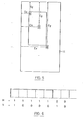
- Fig. 1 shows schematically major components of a word processor suitable for embodying the invention.
- the word processor comprises a keyboard 1, a controller 2, a main memory 3, a refresh buffer 4 and a display 5 of a cathode ray tube (CRT).
- CRT cathode ray tube
- the keyboard 1 has a conventional configuration, and has a number of character entry keys and function keys.
- the function keys include a grid line mode key., specifying grid line mode, a cursor movement key specifying the direction of cursor movement, an enter key used for specifying the start point, the end point and the intersection point of grid lines, description of which is omitted because they are well known in the art.
- the controller 2 processes data supplied from the keyboard 1 according to a program that is stored in a program area 10 of the main memory 3, and includes a processor 6 and counters 7 - 9 for storing information on the locations of the cursor.
- the location information of the cursor stored in the counters 7 - 9 is updated by the processor 6 according to keying of the cursor movement key on the keyboard 1. Operation relating to these counters 7 - 9 is described later in detail.
- a logical page buffer 11 provided in part of the main memory 3 has a plurality of memory locations at least corresponding to the number of character boxes on the screen of the display 5, and stores character information and control information supplied from the keyboard 1 in a predetermined format under control of the controller 2.
- each memory location in the logical page buffer 11 stores a character code representing a character or a symbol to be displayed on the screen of the display 5, and an attribute byte representing an attribute (reverse, highintensity, cursor, etc.) of said character or symbol in a pair.
- V vertical grid line
- H horizontal grid line
- the refresh buffer -4 has a plurality of memory locations corresponding to the number of character boxes on the screen of the display 5. Each of these memory locations stores a character code representing a character or a symbol to be displayed in each character box, and an attribute byte for the character code in a pair.
- a vertical line and a horizontal line can be independently displayed at the left side and the upper end of a character box, respectively, by using the vertical grid line (V) bit and the horizontal grid line (H) bit in the attribute byte (see Fig. 2).
- V vertical grid line
- H horizontal grid line
- a grid line specifying menu is displayed on the screen of the display 5.
- the word processor enters into the tabulating mode.
- a graphic cursor as shown in Fig. 3 is displayed on the screen of the display 5.
- the operator moves the graphic cursor to a desired location on the screen by pressing the cursor movement key, and specifies the start point and then the end point of a grid line, respectively, by pressing the enter key on the keyboard 1.
- the start point of the grid line may be any one of the upper left, the lower left, the upper right or the lower left corners of the box.
- a point on a diagonal line opposing to the start point becomes the end point.
- one of two end points of a grid line to be displayed that is first specified is the start point, while the end point that is specified later is the end point.
- the end point is specified by moving the graphic cursor to the right or the bottom of the rectangular box.
- the function up to now is same as that in the conventional tabulating system.
- the operator presses the cursor movement key to move the graphic cursor to a point within the previously specified rectangular box, and presses the enter key to specify it as an intersection point of a vertical and a horizontal grid line to be drawn in the box. This operation is continued until the operator stops (for example, by pressing a cancel key on the keyboard 1).
- FIG. 4G This example is to finally display a table as shown in Fig. 4G.
- the operator moves the graphic cursor to the location of the upper left corner of a rectangular box not yet displayed on the screen, and presses the enter key to specify that location as the start point (see Fig. 4A). It is noted that dotted lines in the figure indicate the character boxes. Then the graphic cursor is moved to the lower right corner of the rectangular box, which is specified as the end point by pressing the enter key in the same manner as in the above (see Fig. 4B). Thus, the rectangular box is immediately displayed on the screen (see Fig. 4C).
- the graphic cursor is then moved to a point within the box, which is specified as an intersection point by pressing the enter key (see Fig. 4D). This causes a vertical line and a horizontal line passing through.the intersection point to be immediately displayed in the rectangular box (see Fig. 4E).
- the desired table as shown in Fig. 4G is formed on the screen by successively moving the graphic cursor as in Fig. 4F, and correspondingly specifying intersection points.
- the controller 2 in Fig. 1 uses the following counters:
- the script "x" in the first three counters indicates the number of column from the left end of a logical page stored in the logical page buffer 11, while " y " indicates the number of row or line from the start line of the logical page (see Fig. 5).
- H 1
- Step 20 First when the operator presses the grid line mode key on the keyboard 1, it causes the processor 6 in the controller 2 to start the program stored in the program area 10 of the main memory 3 to display the grid line specifying menu on the screen of the display 5 (Step 20).
- the word processor enters the tabulating mode.
- pressing the cursor movement key on the keyboard 1 updates content of the current location counter 9 according to the moving direction of the graphic cursor under control of the processor 6.
- the operator specifies the start point by pressing the enter key at a desired location, content of the current location counter 9 indicating the cursor location at that moment is set in the start point counter 7 (Step 23).
- the processor 6 in the controller 2 takes out the H and the V bits set in each of the line counters 12 by a grid line creating program, and selectively sets the attribute bits representing the left vertical line and the upper horizontal line of each character box at the corresponding attribute byte locations in the refresh buffer 4 (Step 29).
- the processor 6 in the controller 2 takes out the content of each line counter 12 set as described above, and selectively sets the attribute bits representing the left vertical line and the upper horizontal line of each character box to be on at the corresponding attribute location in the refresh buffer 4 (Step 35).
- the invention enables to draw a vertical and a horizontal line simultaneously only by specifying a single point, the intersection of both lines,
Landscapes
- Engineering & Computer Science (AREA)
- Theoretical Computer Science (AREA)
- Physics & Mathematics (AREA)
- General Physics & Mathematics (AREA)
- Computer Hardware Design (AREA)
- Radar, Positioning & Navigation (AREA)
- Remote Sensing (AREA)
- General Engineering & Computer Science (AREA)
- Audiology, Speech & Language Pathology (AREA)
- Artificial Intelligence (AREA)
- General Health & Medical Sciences (AREA)
- Computational Linguistics (AREA)
- Health & Medical Sciences (AREA)
- Human Computer Interaction (AREA)
- Controls And Circuits For Display Device (AREA)
- Digital Computer Display Output (AREA)
- Document Processing Apparatus (AREA)
- Processing Or Creating Images (AREA)
Abstract
Description
- The present invention relates to a tabulating system in a word processor or the like having a display, and more particularly to a tabulating system that enables to draw vertical and horizontal grid lines with less movements of a cursor than in a tabulating system known from the prior art.
- There is a prior tabulating system described in Japanese Published Unexamined Patent Application 58-4432 of Fujitsu wherein two points are specified on a diagonal line of a rectangular box as a start and an end point by a cursor to draw the rectangular box surrounding a table on a screen of a display. Although this tabulating system enables to draw the rectangular box only by specifying two points with the cursor, it is required to specify respective start and end points of vertical and horizontal grid lines with the cursor when they are successively drawn in the rectangular box. Therefore, there is inconvenience to the operator in operation because it is required to move the cursor from the top end to the bottom end of the box, or the left end to the right end again and again.
- It is therefore an object of the present invention to provide an improved tabulating system that is designed to draw a vertical and a horizontal grid lines simultaneously by specifying a single point with the cursor in a rectangular box drawn on a screen of a display to eliminate such disadvantage of the conventional tabulating system.
- To this end, the tabulating system according to the invention comprises a key entry means, a display having a plurality of character boxes on a display screen, a memory means having a plurality of adress- able memory locations at least corresponding to said character boxes, each of the locations storing flag bits for vertical and horizontal grid lines as part of attribute codes indicating display conditions of a corresponding character box, a current location counter for storing both of current horizontal and vertical locations of a cursor, a start point counter for storing both of horizontal and vertical locations of the cursor at a start point when one of two end points on a diagonal line of a rectangular box to be displayed on said display screen is specified as the start points by said key entry means, an end point counter for storing horizontal and vertical locations of the cursor at an end point when another point of said end points is specified as the end point by said key entry means, and a control means for selectively setting said flag bits according to contents of said current location counter, said start point counter and said end point counter so that, when a point in said rectangular box is specified as an intersection point by said key entry means, vertical and horizontal grid lines passing through said intersection point are displayed on said display screen within said rectangular box.
- In advantageous manner the present invention solves the above mentioned object and enables to draw a vertical and a horizontal line simultaneously only by specifying a single point, the intersection of both lines, in a rectangular box with the cursor, and allows to efficiently create a table in a word processor or the like.
- Now a preferred embodiment of the invention is described as example and referring to the attached drawing, in which
- Fig. 1 shows a block diagram illustrating a configuration of an embodiment of the-invention;
- Fig. 2 shows a vertical and a horizontal line displayed at the left and the upper side of a character box, respectively, according to two attribute bits;
- Fig. 3 shows a pattern of a graphic cursor;
- Figs. 4A show the creation processes on the through 4G display screen;
- Fig. 5 shows a correlation of contents of the start point counter, the end point counter and the current location counter;
- Fig. 6 shows correspondence of the content of the line counter and the displayed pattern;
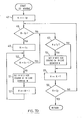
- Figs. 7A show flowcharts illustrating the through 7D tabulating procedures of the preferred embodiment of the invention.
- Fig. 1 shows schematically major components of a word processor suitable for embodying the invention. As shown, the word processor comprises a
keyboard 1, acontroller 2, amain memory 3, arefresh buffer 4 and adisplay 5 of a cathode ray tube (CRT). - The
keyboard 1 has a conventional configuration, and has a number of character entry keys and function keys. The function keys include a grid line mode key., specifying grid line mode, a cursor movement key specifying the direction of cursor movement, an enter key used for specifying the start point, the end point and the intersection point of grid lines, description of which is omitted because they are well known in the art. - The
controller 2 processes data supplied from thekeyboard 1 according to a program that is stored in a program area 10 of themain memory 3, and includes a processor 6 and counters 7 - 9 for storing information on the locations of the cursor. The location information of the cursor stored in the counters 7 - 9 is updated by the processor 6 according to keying of the cursor movement key on thekeyboard 1. Operation relating to these counters 7 - 9 is described later in detail. - A
logical page buffer 11 provided in part of themain memory 3 has a plurality of memory locations at least corresponding to the number of character boxes on the screen of thedisplay 5, and stores character information and control information supplied from thekeyboard 1 in a predetermined format under control of thecontroller 2. In other words, each memory location in thelogical page buffer 11 stores a character code representing a character or a symbol to be displayed on the screen of thedisplay 5, and an attribute byte representing an attribute (reverse, highintensity, cursor, etc.) of said character or symbol in a pair. However, it is assumed for convenience of the description that a vertical grid line (V) bit and a horizontal grid line (H) bit that are part of the attribute byte are stored onseparate line counters 12. - The refresh buffer -4 has a plurality of memory locations corresponding to the number of character boxes on the screen of the
display 5. Each of these memory locations stores a character code representing a character or a symbol to be displayed in each character box, and an attribute byte for the character code in a pair. In this embodiment, it is assumed that a vertical line and a horizontal line can be independently displayed at the left side and the upper end of a character box, respectively, by using the vertical grid line (V) bit and the horizontal grid line (H) bit in the attribute byte (see Fig. 2). However, the character boxes indicated by dotted lines in Fig. 2 are not usually displayed. - Now referring to Figs. 3 and 4A through 4G, it is described what display is performed on the screen of the
display 5, and then the details of each component shown in Fig. 1 are described. - When the operator presses the grid line mode key on the
keyboard 1, a grid line specifying menu is displayed on the screen of thedisplay 5. Then, when a tabulating mode is selected on the menu, the word processor enters into the tabulating mode. In this case, a graphic cursor as shown in Fig. 3 is displayed on the screen of thedisplay 5. The operator moves the graphic cursor to a desired location on the screen by pressing the cursor movement key, and specifies the start point and then the end point of a grid line, respectively, by pressing the enter key on thekeyboard 1. When it is intended to 3raw a rectangular box, the start point of the grid line may be any one of the upper left, the lower left, the upper right or the lower left corners of the box. A point on a diagonal line opposing to the start point becomes the end point. In other words, one of two end points of a grid line to be displayed that is first specified is the start point, while the end point that is specified later is the end point. In the following, it is assumed for convenience of the description that the upper left corner of the rectangular box is specified as the start point. In that case, the end point is specified by moving the graphic cursor to the right or the bottom of the rectangular box. The function up to now is same as that in the conventional tabulating system. Then, the operator presses the cursor movement key to move the graphic cursor to a point within the previously specified rectangular box, and presses the enter key to specify it as an intersection point of a vertical and a horizontal grid line to be drawn in the box. This operation is continued until the operator stops (for example, by pressing a cancel key on the keyboard 1). - To understand the above operation more clearly, it is described in more detail by referring to an example shown in Figs. 4A through 4F. This example is to finally display a table as shown in Fig. 4G. First, the operator moves the graphic cursor to the location of the upper left corner of a rectangular box not yet displayed on the screen, and presses the enter key to specify that location as the start point (see Fig. 4A). It is noted that dotted lines in the figure indicate the character boxes. Then the graphic cursor is moved to the lower right corner of the rectangular box, which is specified as the end point by pressing the enter key in the same manner as in the above (see Fig. 4B). Thus, the rectangular box is immediately displayed on the screen (see Fig. 4C). The graphic cursor is then moved to a point within the box, which is specified as an intersection point by pressing the enter key (see Fig. 4D). This causes a vertical line and a horizontal line passing through.the intersection point to be immediately displayed in the rectangular box (see Fig. 4E). The desired table as shown in Fig. 4G is formed on the screen by successively moving the graphic cursor as in Fig. 4F, and correspondingly specifying intersection points.
- To display the grid lines as above, the
controller 2 in Fig. 1 uses the following counters: - - Start point counter (Sx, Sy) 7
- - End point counter (Ex, Ey) 8
- - Current location counter (Cx, Cy) 9
- - Line counters (H, V) 12
- The script "x" in the first three counters indicates the number of column from the left end of a logical page stored in the
logical page buffer 11, while "y" indicates the number of row or line from the start line of the logical page (see Fig. 5). - A pair of line counters 12 are used for each of displayed lines, and one of the paired counters 12 contains the horizontal grid line bit H = 1 if it is required to display a horizontal line at the upper end in each character box for corresponding displayed lines, or the other of the paired counters 12 contains the vertical grid line bit V = I if it is required to display a vertical line at the left end (see Fig. 6). Now the tabulating procedure according to the invention is described in more detail by referring to Figs. 7A through 7D.
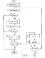
- First when the operator presses the grid line mode key on the
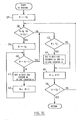
keyboard 1, it causes the processor 6 in thecontroller 2 to start the program stored in the program area 10 of themain memory 3 to display the grid line specifying menu on the screen of the display 5 (Step 20). When the operator selects the tabulating mode on the menu, the word processor enters the tabulating mode. Then pressing the cursor movement key on thekeyboard 1 updates content of thecurrent location counter 9 according to the moving direction of the graphic cursor under control of the processor 6. In this case, when the operator specifies the start point by pressing the enter key at a desired location, content of thecurrent location counter 9 indicating the cursor location at that moment is set in the start point counter 7 (Step 23). Then when the end point is specified, content of thecurrent location counter 9 indicating the cursor location at that moment is set in the end point counter 8 (Step 26). Succeedingly by calling S1 routine of Fig. 7C (Step 28), contents of the line counters 12, corresponding to each of line Sy to line Ey in thelogical page buffer 11, are separately set. That is, all H bits for columns Sx to Ex - 1 are set to be on in the line counters 12 corresponding to two lines of Sy and Ey (Steps 38 and 42), and two V bits for columns Sx and Ex are set to be on in the line counters 12 corresponding to all lines from Sy to Ey - 1 (Steps 43 and 44). It is noted that "N" and "M" inSteps main memory 3 that are used for Sl routine. - The processor 6 in the
controller 2 takes out the H and the V bits set in each of the line counters 12 by a grid line creating program, and selectively sets the attribute bits representing the left vertical line and the upper horizontal line of each character box at the corresponding attribute byte locations in the refresh buffer 4 (Step 29). - Thus, the rectangular box as shown in Fig. 4C is displayed on the screen. Up to this stage, the procedure is the same as that of the conventional tabulating system.
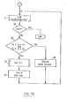
- Then, when an intersection point is specified as shown in Fig. 7B, if the content (Cx, Cy) of the
current location counter 9 indicating the cursor location at that moment satisfies
logical page buffer 11 are updated by calling S2 routine of Fig. 7D (Step 34). The S2 routine sets all H bit for columns Sx to Ex - 1 to be on in theline counter 12 corresponding to line Cy (Steps 48 through 52), and sets V bits for column Cx to be on in the line counters 12 corresponding to all lines from Sy to Ey - 1 (Steps 53 and 54). - Then, the processor 6 in the
controller 2 takes out the content of each line counter 12 set as described above, and selectively sets the attribute bits representing the left vertical line and the upper horizontal line of each character box to be on at the corresponding attribute location in the refresh buffer 4 (Step 35). - By repeating
Steps 31 to 35, the table as shown in Fig. 4G is ultimately displayed on the screen. - If an intersection point is specified to be Sx = Cx or Ex = Cx, only a vertical line is drawn in the rectangular box, while, if it is specified to be Sy = Cy or Ey = Cy, only a horizontal line is drawn in the rectangular box.
- As described, the invention enables to draw a vertical and a horizontal line simultaneously only by specifying a single point, the intersection of both lines,
- in a rectangular box with the cursor, and allows to efficiently create a table in a word processor or the like.
Claims (2)
Applications Claiming Priority (2)
| Application Number | Priority Date | Filing Date | Title |
|---|---|---|---|
| JP59099725A JPS60251473A (en) | 1984-05-19 | 1984-05-19 | Tabulation system |
| JP99725/84 | 1984-05-19 |
Publications (3)
| Publication Number | Publication Date |
|---|---|
| EP0162380A2 true EP0162380A2 (en) | 1985-11-27 |
| EP0162380A3 EP0162380A3 (en) | 1989-10-18 |
| EP0162380B1 EP0162380B1 (en) | 1992-07-29 |
Family
ID=14255044
Family Applications (1)
| Application Number | Title | Priority Date | Filing Date |
|---|---|---|---|
| EP85105725A Expired - Lifetime EP0162380B1 (en) | 1984-05-19 | 1985-05-10 | Tabulating system |
Country Status (5)
| Country | Link |
|---|---|
| US (1) | US4728945A (en) |
| EP (1) | EP0162380B1 (en) |
| JP (1) | JPS60251473A (en) |
| KR (1) | KR890003033B1 (en) |
| DE (1) | DE3586406D1 (en) |
Families Citing this family (10)
| Publication number | Priority date | Publication date | Assignee | Title |
|---|---|---|---|---|
| JP2611969B2 (en) * | 1986-02-04 | 1997-05-21 | キヤノン株式会社 | Document processing device |
| JPH07123281B2 (en) * | 1986-03-24 | 1995-12-25 | キヤノン株式会社 | Information processing equipment |
| JP2532213B2 (en) * | 1986-07-11 | 1996-09-11 | セイコーエプソン株式会社 | Ruled line creation device |
| JPH0711799B2 (en) * | 1986-12-26 | 1995-02-08 | 株式会社東芝 | Typesetting system |
| JPS649507A (en) * | 1987-07-02 | 1989-01-12 | Fanuc Ltd | Nc data preparing system |
| US4814884A (en) * | 1987-10-21 | 1989-03-21 | The United States Of America As Represented By The Secretary Of The Air Force | Window generator |
| JPH0758487B2 (en) * | 1990-01-08 | 1995-06-21 | インターナショナル・ビジネス・マシーンズ・コーポレーション | Table editing device |
| US5526018A (en) * | 1992-10-02 | 1996-06-11 | Foundation Microsystems, Inc. | Stretching scales for computer documents or drawings |
| JP2987033B2 (en) * | 1993-08-31 | 1999-12-06 | アルプス電気株式会社 | Coordinate input device |
| US20080180413A1 (en) * | 2007-01-29 | 2008-07-31 | Farn Brian G | Method, system, and program product for controlling grid lines in a user interface |
Citations (3)
| Publication number | Priority date | Publication date | Assignee | Title |
|---|---|---|---|---|
| US4146879A (en) * | 1977-04-12 | 1979-03-27 | International Business Machines Corporation | Visual display with column separators |
| US4291305A (en) * | 1978-09-05 | 1981-09-22 | Fuji Photo Film Co., Ltd. | Method for generating format lines and character data in an image scanning system |
| US4302755A (en) * | 1978-09-20 | 1981-11-24 | Ing. C. Olivetti & C., S.P.A. | Visual display unit and display method for a programmable computer |
Family Cites Families (11)
| Publication number | Priority date | Publication date | Assignee | Title |
|---|---|---|---|---|
| CA943213A (en) * | 1971-09-30 | 1974-03-05 | Lektromedia Ltd. | Low resolution graphics for crt displays |
| BE791200R (en) * | 1971-11-12 | 1973-03-01 | Western Electric Co | APPARATUS AND METHOD FOR TRANSFORMING DIGITAL INFORMATION INTO GRAPHIC IMAGES AND FOR THE |
| US4063223A (en) * | 1976-08-11 | 1977-12-13 | International Business Machines Corporation | Nondestructive cursors in AC plasma displays |
| JPS5643686A (en) * | 1979-09-18 | 1981-04-22 | Mitsubishi Electric Corp | Tabulation system |
| US4408301A (en) * | 1979-11-06 | 1983-10-04 | Tokyo Shibaura Denki Kabushiki Kaisha | Picture information filing system |
| US4425559A (en) * | 1980-06-02 | 1984-01-10 | Atari, Inc. | Method and apparatus for generating line segments and polygonal areas on a raster-type display |
| JPS57185530A (en) * | 1981-05-11 | 1982-11-15 | Hitachi Ltd | Input system for ruled line |
| JPS584432A (en) * | 1981-06-30 | 1983-01-11 | Fujitsu Ltd | Listing system |
| JPS5850039A (en) * | 1981-09-21 | 1983-03-24 | Fujitsu Ltd | List output method |
| US4454507A (en) * | 1982-01-04 | 1984-06-12 | General Electric Company | Real-time cursor generator |
| US4420770A (en) * | 1982-04-05 | 1983-12-13 | Thomson-Csf Broadcast, Inc. | Video background generation system |
-
1984
- 1984-05-19 JP JP59099725A patent/JPS60251473A/en active Granted
-
1985
- 1985-02-05 KR KR1019850000711A patent/KR890003033B1/en not_active IP Right Cessation
- 1985-05-10 DE DE8585105725T patent/DE3586406D1/en not_active Expired - Lifetime
- 1985-05-10 EP EP85105725A patent/EP0162380B1/en not_active Expired - Lifetime
- 1985-05-22 US US06/736,879 patent/US4728945A/en not_active Expired - Fee Related
Patent Citations (3)
| Publication number | Priority date | Publication date | Assignee | Title |
|---|---|---|---|---|
| US4146879A (en) * | 1977-04-12 | 1979-03-27 | International Business Machines Corporation | Visual display with column separators |
| US4291305A (en) * | 1978-09-05 | 1981-09-22 | Fuji Photo Film Co., Ltd. | Method for generating format lines and character data in an image scanning system |
| US4302755A (en) * | 1978-09-20 | 1981-11-24 | Ing. C. Olivetti & C., S.P.A. | Visual display unit and display method for a programmable computer |
Also Published As
| Publication number | Publication date |
|---|---|
| EP0162380A3 (en) | 1989-10-18 |
| DE3586406D1 (en) | 1992-09-03 |
| US4728945A (en) | 1988-03-01 |
| JPH0374428B2 (en) | 1991-11-26 |
| KR890003033B1 (en) | 1989-08-19 |
| EP0162380B1 (en) | 1992-07-29 |
| JPS60251473A (en) | 1985-12-12 |
| KR850008012A (en) | 1985-12-11 |
Similar Documents
| Publication | Publication Date | Title |
|---|---|---|
| US4785296A (en) | Method and system for displaying image data | |
| USRE34835E (en) | Method and apparatus for editing document in colors | |
| US4710762A (en) | Display screen control system | |
| KR910005366B1 (en) | Crt/plasma display controller | |
| EP0162380A2 (en) | Tabulating system | |
| EP0750287A2 (en) | An image creation apparatus | |
| JPH07104756B2 (en) | Information processing method | |
| GB2284694A (en) | Multiple font display | |
| US4539563A (en) | Method and apparatus for drawing lines | |
| JPH06289843A (en) | Image display processor | |
| JPH0247779B2 (en) | ||
| JPH0318999Y2 (en) | ||
| JPS5890692A (en) | Display controller for character information processor | |
| JPS5949609B2 (en) | Calibration position indication method | |
| JP2680805B2 (en) | Graphic coordinate controller | |
| JPH0413727Y2 (en) | ||
| JP3136852B2 (en) | Touch panel screen creation method and device | |
| EP0191382A2 (en) | Display controller | |
| JPS5936299B2 (en) | screen display device | |
| JP2922578B2 (en) | Character processor | |
| JPH01111285A (en) | Character recognition result confirmation/correction processing system for graphic recognizing processing | |
| JPS63201820A (en) | Picture layout setting system for interactive computer system | |
| JPS63250693A (en) | Character telop generator | |
| JPS60151777A (en) | Documentation device | |
| JPS6216435B2 (en) |
Legal Events
| Date | Code | Title | Description |
|---|---|---|---|
| PUAI | Public reference made under article 153(3) epc to a published international application that has entered the european phase |
Free format text: ORIGINAL CODE: 0009012 |
|
| AK | Designated contracting states |
Designated state(s): DE FR GB |
|
| 17P | Request for examination filed |
Effective date: 19860325 |
|
| PUAL | Search report despatched |
Free format text: ORIGINAL CODE: 0009013 |
|
| AK | Designated contracting states |
Kind code of ref document: A3 Designated state(s): DE FR GB |
|
| 17Q | First examination report despatched |
Effective date: 19910130 |
|
| GRAA | (expected) grant |
Free format text: ORIGINAL CODE: 0009210 |
|
| AK | Designated contracting states |
Kind code of ref document: B1 Designated state(s): DE FR GB |
|
| PG25 | Lapsed in a contracting state [announced via postgrant information from national office to epo] |
Ref country code: FR Effective date: 19920729 Ref country code: DE Effective date: 19920729 |
|
| REF | Corresponds to: |
Ref document number: 3586406 Country of ref document: DE Date of ref document: 19920903 |
|
| EN | Fr: translation not filed | ||
| PG25 | Lapsed in a contracting state [announced via postgrant information from national office to epo] |
Ref country code: GB Effective date: 19930510 |
|
| PLBE | No opposition filed within time limit |
Free format text: ORIGINAL CODE: 0009261 |
|
| STAA | Information on the status of an ep patent application or granted ep patent |
Free format text: STATUS: NO OPPOSITION FILED WITHIN TIME LIMIT |
|
| 26N | No opposition filed | ||
| GBPC | Gb: european patent ceased through non-payment of renewal fee |
Effective date: 19930510 |