EP0146865B1 - Method of generating pseudo-random trains of binary signals - Google Patents
Method of generating pseudo-random trains of binary signals Download PDFInfo
- Publication number
- EP0146865B1 EP0146865B1 EP84115129A EP84115129A EP0146865B1 EP 0146865 B1 EP0146865 B1 EP 0146865B1 EP 84115129 A EP84115129 A EP 84115129A EP 84115129 A EP84115129 A EP 84115129A EP 0146865 B1 EP0146865 B1 EP 0146865B1
- Authority
- EP
- European Patent Office
- Prior art keywords
- module
- symbol
- shift register
- generator
- symbol generator
- Prior art date
- Legal status (The legal status is an assumption and is not a legal conclusion. Google has not performed a legal analysis and makes no representation as to the accuracy of the status listed.)
- Expired - Lifetime
Links
Images


Classifications
-
- H—ELECTRICITY
- H03—ELECTRONIC CIRCUITRY
- H03K—PULSE TECHNIQUE
- H03K3/00—Circuits for generating electric pulses; Monostable, bistable or multistable circuits
- H03K3/84—Generating pulses having a predetermined statistical distribution of a parameter, e.g. random pulse generators
Definitions
- the method made known by the above German patent is based on the prerequisite for the formation of long periods that the pulse sequences supplied by the individual pulse sequence generators, namely counters and / or feedback shift registers, are relatively prime to one another in the number of their bit positions per period, which in turn means that What is achieved is that the number of bit positions per period is a prime number or the product of fewer prime numbers.
- the linking of several binary character strings with different, non-prime period lengths results in a binary character string with a period length equal to the product of the period length of the binary character strings subject to the linking.
- the method according to the invention has the advantages that a much longer period for the binary string can be achieved with little additional circuitry.
- the basic idea of the invention is that pulse train generators can also be used which deliver pulse trains which are equal in number to each other in the number of their bit positions per period. So that total pulse sequences result, the period length of which results from the multiplication of the individual period lengths of the generators, the pulse sequences of the individual generators are kept constantly offset, i.e. after the period of the first generator has elapsed, the phase position of the pulse sequence of the second generator is delayed by hiding a clock pulse. In this way it is possible to generate very long total periods without having to use high prime numbers and thus long shift register chains.
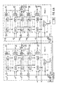
- FIG. 1 an embodiment for a generator module according to the invention is shown.
- Figures 2 to 4 show different linking options of several generator modules.
- the generator module according to FIG. 1 shows the linking of several partial sequences TFa to TFt to form an output sequence QZF with quasi-random properties.
- the binary character strings are processed into a quasi-random binary character string QZF in the effect groups 1 to 6 combined by dash-dotted frames in the direction of action from top to bottom.
- the effect modules 1, 3 and 4 contain partial sequence generators TFa to TFt with different, ie non-prime cycle periods.
- the partial sequence generators can be, for example, as feedback shift registers of maximum period, which is preferably a prime number or a product of a few prime numbers.
- the effect modules 2 and 5 contain devices for the logical combination of binary signals. AND, OR, exclusive OR elements, allocators, multiplexers, selectors, couplers etc. can be used for this.
- product-forming circuits are used in the functional assembly 2 and 5, which multiply the partial sequences a to f by the partial sequences m to g. The result is fed to the further effect module 5, which has further assignments and multiplications with partial sequences t to n from group 4.
- the effect module 6 summarizes the results from the effect module 5 and forms the output sequence QZF, which is therefore dependent on all individual partial sequences TFa to TFt.
- There are several setting options for such a generator arrangement firstly by presetting the partial sequence generators, secondly by the controllability of the assignors in the effect levels 2 and 5, whereby the assignment can be changed, thirdly in the controllability of the shift register chains in the effect areas 1, 3 and 4 by varying the feedback of these shift registers, and finally fourthly in a further interference from the shift register chains of the action levels 1, 3 and 4, by means of gate circuits TS, TS1 to TS4, individual clocks for the shift register chains of an action level or of the entire module are hidden.
- the action levels of the shift register stages and the allocators additionally have logic circuits V1 to V5 which monitor the period of the partial sequence generators.
- the logic circuits V1, V3 and V4 of the action levels of the feedback shift register chains are conjunctive circuits which output a binary one at their output when a certain word is formed by all partial sequences active in the respective group. This word occurs once per round of the group period and then leads to the representative signal at the outputs a11, a12 and a13.
- a further conjunct circuit V combines these three outputs and provides a signal statement representative of the total period of the generator module at output a10.
- the logic circuits V2 and V5 form the sum signals from the partial sequence signals TFa to TFm or TFa to TFt present in the respective effect group.
- Binary character strings with the maximum period length equal to the product of the lengths of all binary character strings supplied to the logic circuits are thus present at the outputs a21 and a22 of these sum circuits.
- the signal inputs e21 and e22 act on the effect modules 2 and 5 in such a way that within these modules the logical combination of the partial sequence signals and / or the assignment of the input signals of these modules to their outputs depending on the logical value of the input signals at e21 and e22 can be changed.
- the effect of the individual connections between the modules is now described.
- the connection a11 from module 1 to e11 module 2 has the effect that whenever the function module 1 (stage 1) of module 1 reports a period signal a11, an operating cycle for group 1 of module 2 is faded out via input circuit e11 of module 2 .
- the partial sequence registers of the effect module 1 of the module 2 appear after each masking of the clock phase-shifted by one bit with respect to the registers of the group 1 of the module 1.
- the total period of these two is equal to the product of the periods of the two quasi-random sequences QZF1 and QZF2.
- the connection a21 from module 1 to e21 from module 2 has the effect that the logic operations in group 2 of module 2 are influenced as a function of the sum signals at a21.
- the connection from a22 module 1 to e22 module 2 works in the same way.
- the two feedback connections from a21 module 2 to e21 module 1 and a22 module 2 to e22 module 1 work in the same way and thus also allow changes in module 1 depending on the respective setting in module 2.
- FIG. 3 Another connection between two modules is shown in FIG. 3.
- the clock is hidden by the connection a10 module 1 to e10 module 2 whenever module 1 has run through a period.
- the two connections a22 from module 1 to e22 module 2 and from a22 module 2 to e22 module 1 influence the logic logic circuits in the functional unit 5, depending on all partial sequences of the other generator module.
- FIG. 4 which consists of the two sub-figures 4a and b on one sheet each, shows a configuration with four modules which are connected in the same way as the two generator modules according to FIG. 3.
- a clock masking takes place in a generator module whenever one of the previous generator modules runs through its period.
- the first generator module 1 works without clock suppression, the input e10 of its clock gate circuit TS is assigned a binary zero.
- an OR gate is inserted in front of the lock input of the gate circuit TS for blocking the clock for the entire module, on the inputs of which the signals a10 of the previous generator modules 1, 2 and 1, which are representative of the entire period, 2nd and 3 are guided.
- the ring connection circuit from a22 to e22 in action level 5 exists in this arrangement according to FIG. 4 as well as in FIG. 3, the ring only being expanded from two to four generator modules.
Abstract
Description
Die Erfindung betrifft ein Verfahren zum Erzeugen zufallsähnlicher Binärzeichenfolgen gemäß Oberbegriff des Patentanspruches 1.
Ein solches Verfahren ist durch die DE -C- 24 51 711 bekannt geworden.
Zufallsähnliche Zeichenfolgen werden beispielsweise für die Ver- bzw. Entschlüsselung von Informationen in Chiffriereinrichtungen benötigt. Diese Folgen müssen eine Reihe von Eigenschaften aufweisen, um den Forderungen der Kryptotechnik nachzukommen:
- a)
- Lange Periode (quasi unendlich)
- b)
- Wiederholbarkeit
- c)
- statistisches, d.h. einem echten Zufallstext nahekommendes Testverhalten
- d)
- komplexe Bildungsgesetze
- e)
- eine Vielzahl von Möglichkeiten zur Einstellung und Änderung der Bildungsgesetze durch Programme
- f)
- kalkulierbare Dechiffriersicherheit
- g)
- hohe Arbeitsgeschwindigkeiten.
Such a method is known from DE-C-24 51 711.
Randomly similar character strings are required, for example, for the encryption or decryption of information in encryption devices. These consequences must have a number of properties in order to meet the requirements of crypto technology:
- a)
- Long period (almost infinite)
- b)
- Repeatability
- c)
- Statistical test behavior, that is, a test that comes close to a real random text
- d)
- complex educational laws
- e)
- a variety of ways to set and change educational laws through programs
- f)
- calculable decryption security
- G)
- high working speeds.
Das durch die obige deutsche Patentschrift bekanntgewordene Verfahren geht von der für das Bilden langer Perioden notwendigen Voraussetzung aus, daß die von den einzelnen Impulsfolgegeneratoren, nämlich Zähler und/oder rückgekoppelte Schieberegister, gelieferten Impulsfolgen in der Anzahl ihrer Bitstellen je Periode untereinander teilerfremd sind, was dadurch erreicht wird, daß die Anzahl der Bitstellen je Periode eine Primzahl oder das Produkt weniger Primzahlen ist.
Die Verknüpfung mehrerer Binärzeichenfolgen mit unterschiedlichen, teilerfremden Periodenlängen ergibt eine Binärzeichenfolge mit einer Periodenlänge gleich dem Produkt der Periodenlänge der der Verknüpfung unterworfenen Binärzeichenfolgen.
Wiederholtes Verknüpfen verschiedener Binärzeichenfolgen mit teilerfremden Periodenlängen erlaubt das Gewinnen von Binärzeichenfolgen mit extrem langen Perioden, und es können durch Steuermöglichkeiten für Zähler und Schieberegister die einzelnen Binärzeichenfolgen und damit auch die Binärzeichenfolge mit extrem langer Periode fortlaufend in unregelmäßiger Weise geändert werden. Weiterhin werden die zu verknüpfenden Binärzeichenfolgen fortlaufend untereinander getauscht, indem die von den einzelnen Teilfolgegeneratoren bzw. Schieberegistern gelieferten Binärzeichenfolgen als Störimpulsfolgen durch gesteuerte Zuordnerschaltungen in fortlaufendem und unregelmäßigem Wechsel anderen rückgekoppelten Schieberegistern oder anderen Eingängen eines rückgekoppelten Schieberegisters zugeführt werden. Mit einem solchen Zeichengenerator erzielt man zwar eine sehr lange Periode, doch, will man noch eine größere Periodenlänge erreichen, so steigt der Schaltungsaufwand sehr steil an, weil aufgrund der Voraussetzung, daß die von den einzelnen Impulsfolgegeneratoren gelieferten Impulsfolgen in der Anzahl ihrer Bitstellen je Periode untereinander teilerfremd sind, erforderlich ist, daß höhere Primzahlen zusätzlich verwendet werden müssen, was sich durch zusätzlichen Einsatz von entsprechend längeren Schieberegistern ausdrückt.
Technische und technologische Fortschritte in der Datenverarbeitung führten und führen zu höheren Verarbeitungs- und Übertragungsgeschwindigkeiten. Damit ist auch eine Erhöhung der Arbeitsgeschwindigkeit eines Zeichengenerators der Kryptogeräte erforderlich. Die Forderung nach erhöhter Arbeitsgeschwindigkeit der Zeichengeneratoren und die Tatsache der höheren Geschwindigkeit von Datenverarbeitungsanlagen ziehen aber auch eine weitere Verlängerung der Periodendauer der Binärzeichenfolgen mit sich, um eine entsprechende Kryptosicherheit zu gewährleisten. Bei der zeichenweisen oder wortweisen Verschlüsselung von Texten, bei der für jede Bitstelle ein separater Zeichen generator vorgesehen ist, die nach unterschiedlichen Bildungsgesetzen arbeiten, ist es daher erforderlich, daß diese separaten Zeichengeneratoren jeweils einen unterschiedlichen Aufbau und eine unterschiedliche Anordnung aufweisen. Der Aufwand hierfür, auch unter der Voraussetzung der unterschiedlichen teilerfremden Impulsfolgen gesehen, ist enorm.The method made known by the above German patent is based on the prerequisite for the formation of long periods that the pulse sequences supplied by the individual pulse sequence generators, namely counters and / or feedback shift registers, are relatively prime to one another in the number of their bit positions per period, which in turn means that What is achieved is that the number of bit positions per period is a prime number or the product of fewer prime numbers.
The linking of several binary character strings with different, non-prime period lengths results in a binary character string with a period length equal to the product of the period length of the binary character strings subject to the linking.
Repeated linking of different binary strings with non-prime period lengths allows binary strings with extremely long periods to be obtained, and the individual binary strings and thus the binary string with an extremely long period can be changed continuously in irregular ways by means of controls for counters and shift registers. Furthermore, the binary character strings to be linked are continuously exchanged with one another by supplying the binary character strings supplied by the individual partial sequence generators or shift registers as interference pulse sequences through controlled assigner circuits in continuous and irregular alternation to other feedback shift registers or other inputs of a feedback shift register. With such a character generator you can achieve a very long period, but if you want to achieve a longer period, the circuitry increases very steeply, because on the condition that the pulse trains supplied by the individual pulse train generators have the number of their bit positions per period are relatively prime to each other, it is necessary that higher prime numbers must also be used, which is expressed by the additional use of correspondingly longer shift registers.
Technological and technological advances in data processing have led to higher processing and transmission speeds. This also requires an increase in the working speed of a character generator of the crypto devices. However, the demand for increased working speed of the character generators and the fact that data processing systems are faster also entail a further extension of the period of the binary character strings in order to ensure appropriate crypto security. With character-by-word or word-by-word encryption of text, with a separate character for each bit position is provided generator that work according to different education laws, it is therefore necessary that these separate character generators each have a different structure and a different arrangement. The effort required for this, even when considering the different non-prime impulse sequences, is enormous.
Die der Erfindung zugrundeliegende Aufgabe war, ein Verfahren der eingangs beschriebenen Art anzugeben, welches bei wenig zusätzlichem Aufwand zufallsähnliche Binärzeichenfolgen mit für sehr viel längerer Periode zu liefern im Stande ist.
Die Lösung erfolgt mit den im Patentanspruch 1 angegebenen Merkmalen.
Die Unteransprüche geben vorteilhafte Weiterbildungen des erfindungsgemäßen Verfahrens an.The object on which the invention is based was to specify a method of the type described at the outset which, with little additional outlay, is able to supply randomly similar binary character strings with for a much longer period.
The solution is achieved with the features specified in
The subclaims indicate advantageous developments of the method according to the invention.
Das erfindungsgemäße Verfahren weist die Vorteile auf, daß mit geringem zusätzlichem Schaltungsaufwand eine wesentlich längere Periodendauer für die Binärzeichenfolge erreicht werden kann. Der Grundgedanke der Erfindung besteht darin, daß auch Impulsfolgengeneratoren verwendet werden können, welche Impulsfolgen liefern, die in der Anzahl ihrer Bitstellen je Periode untereinander teilergleich sind. Damit sich Gesamtimpulsfolgen ergeben, deren Periodenlänge sich aus der Multiplikation der Einzelperiodenlängen der Generatoren ergibt, werden die Impulsfolgen der Einzelgeneratoren laufend in Versatz gehalten, d.h. nach Ablauf der Periode des ersten Generators wird die Phasenlage der Impulsfolge des zweiten Generators durch Ausblenden eines Taktimpulses verzögert.
Auf diese Weise ist es möglich, sehr lange Gesamtperioden zu erzeugen, ohne hohe Primzahlen und damit lange Schieberegisterketten benutzen zu müssen. Mit dem geringeren zusätzlichen Schaltungsaufwand ist auch ein kleinerer zusätzlicher Raumbedarf sowie eine geringere zusätzliche Verlustleistung verbunden. Von großem Vorteil ist auch die Verwendungsmöglichkeit von in sich vollkommen gleichen Generatormoduln. Dadurch ergibt sich wiederum die Möglichkeit der Integration der Schaltungsanordnung in einem Großschaltkreis. Durch diese Realisierungsmöglichkeit als Großschaltkreis geben sich wiederum ein kleinerer Raumbedarf, eine geringere Verlustleistung und geringere Kosten. Zusätzlich erbringt der Großschaltkreis eine höhere Zuverlässigkeit und ermöglicht hohe Arbeitsgeschwindigkeiten.The method according to the invention has the advantages that a much longer period for the binary string can be achieved with little additional circuitry. The basic idea of the invention is that pulse train generators can also be used which deliver pulse trains which are equal in number to each other in the number of their bit positions per period. So that total pulse sequences result, the period length of which results from the multiplication of the individual period lengths of the generators, the pulse sequences of the individual generators are kept constantly offset, i.e. after the period of the first generator has elapsed, the phase position of the pulse sequence of the second generator is delayed by hiding a clock pulse.
In this way it is possible to generate very long total periods without having to use high prime numbers and thus long shift register chains. With the lower additional circuit complexity, there is also a smaller additional space requirement and a smaller additional one Power loss connected. Another great advantage is the possibility of using generator modules that are completely identical in themselves. This in turn results in the possibility of integrating the circuit arrangement in a large circuit. This implementation option as a large circuit in turn results in a smaller space requirement, a lower power loss and lower costs. In addition, the large circuit provides greater reliability and enables high working speeds.
Es folgt nun die Beschreibung der Erfindung anhand der Figuren.
In Figur 1 ist ein Ausführungsbeispiel für einen Generatormodul gemäß der Erfindung dargestellt. Die Figuren 2 bis 4 zeigen verschiedene Verknüpfungsmöglichkeiten mehrerer Generatormodule.
Der Generatormodul gemäß Figur 1 zeigt die Verknüpfung mehrerer Teilfolgen TFa bis TFt zu einer Ausgangsfolge QZF mit quasizufälligen Eigenschaften. In der Anordnung nach Figur 1 werden in den durch strichpunktierte Rahmen zusammengefaßte Wirkungsgruppen 1 bis 6 in der Wirkungsrichtung von oben nach unten die binären Zeichenfolgen zu einer Quasizufallsbinärzeichenfolge QZF aufbereitet. Die Wirkungsbaugruppen 1, 3 und 4 enthalten Teilfolgegeneratoren TFa bis TFt mit unterschiedlichen, d.h. teilerfremden Umlaufperioden. Die Teilfolgegeneratoren können beispielsweise als rückgekoppelte Schieberegister maximaler Periode sein, die vorzugsweise eine Primzahl oder ein Produkt aus wenigen Primzahlen ist. Die Wirkungsbaugruppen 2 und 5 enthalten Einrichtungen zur logischen Verknüpfung von Binärsignalen. Es können hierfür UND-, ODER-, Exlusiv- ODER-Glieder, Zuordner, Multiplexer, Wähler, Koppler usw. verwendet werden. In dem Ausführungsbeispiel nach Figur 1 werden in der Wirkungsbaugruppe 2 und 5 Produkt bildende Schaltungen verwendet, welche die Teilfolgen a bis f mit den Teilfolgen m bis g multipliziert. Das Ergebnis wird der weiteren Wirkungsbaugruppe 5 zugeführt, welche weitere Zuordnungen und Multiplikationen mit Teilfolgen t bis n aus der Gruppe 4 durchführt. Die Wirkungsbaugruppe 6 faßt die Ergebnisse aus der Wirkungsbaugruppe 5 zusammen und bildet die Ausgangsfolge QZF, die somit abhängig ist von allen einzelnen Teilfolgen TFa bis TFt.
Für eine solche Generatoranordnung gibt es mehrere Einstellmöglichkeiten, erstens durch eine Voreinstellung der Teilfolgegeneratoren, zweitens durch die Steuerbarkeit der Zuordner in den Wirkungsebenen 2 und 5, wobei die Zuordnung geändert werden kann, drittens in der Steuerbarkeit der Schieberegisterketten in den Wirkungsbereichen 1, 3 und 4, indem die Rückkoppelung dieser Schieberegister variiert wird, und schließlich viertens in einer weiteren Störbeeinflußung der Schieberegisterketten der Wirkungsebenen 1, 3 und 4, indem mittels Torschaltungen TS, TS1 bis TS4 einzelne Takte für die Schieberegisterketten einer Wirkungsebene oder des ganzen Moduls ausgeblendet werden.
Die Wirkungsebenen der Schieberegisterstufen und der Zuordner weisen zusätzlich Verknüpfungsschaltungen V1 bis V5 auf, welche die Periode der Teilfolgegeneratoren überwachen. Die Verknüpfungsschaltungen Vl, V3 und V4 der Wirkungsebenen der rückgekoppelten Schieberegisterketten sind Konjuktionsschaltungen, welche eine binäre Eins an ihrem Ausgang abgeben, wenn ein bestimmtes Wort durch alle in der jeweiligen Gruppe aktiven Teilfolgen gebildet wird. Dieses Wort tritt einmal je Umlauf der Gruppenperiode auf und führt dann zu dem repräsentativen Signal an den Ausgängen a11, a12 und a13. Eine weitere Konjunktionsschaltung V faßt diese drei Ausgänge zusammen und führt am Ausgang a10 ein für die Gesamtperiode des Generatormoduls repräsentative Signalaussage. Die Verknüpfungsschaltungen V2 und V5 bilden die Summensignale aus den in der jeweiligen Wirkungsgruppe anliegenden Teilfolgensignale TFa bis TFm bzw. TFa bis TFt. An den Ausgängen a21 bzw. a22 dieser Summenschaltungen stehen damit Binärzeichenfolgen mit der maximalen Periodenlänge gleich dem Produkt der Längen aller der Verknüpfungsschaltungen zugeführten Binärzeichenfolgen an. Die Signaleingänge e21 und e22 wirken auf die Wirkungsbaugruppen 2 bzw. 5 in der Art, daß innerhalb dieser Baugruppen die logische Verknüpfung der Teilfolgen-Signale und/oder die Zuordnung der Eingangssignale dieser Baugruppen zu deren Ausgängen in Abhängigkeit der logischen Wertigkeit der Eingangssignale an e21 und e22 verändert werden.There now follows the description of the invention with reference to the figures.
In Figure 1, an embodiment for a generator module according to the invention is shown. Figures 2 to 4 show different linking options of several generator modules.
The generator module according to FIG. 1 shows the linking of several partial sequences TFa to TFt to form an output sequence QZF with quasi-random properties. In the arrangement according to FIG. 1, the binary character strings are processed into a quasi-random binary character string QZF in the
There are several setting options for such a generator arrangement, firstly by presetting the partial sequence generators, secondly by the controllability of the assignors in the
The action levels of the shift register stages and the allocators additionally have logic circuits V1 to V5 which monitor the period of the partial sequence generators. The logic circuits V1, V3 and V4 of the action levels of the feedback shift register chains are conjunctive circuits which output a binary one at their output when a certain word is formed by all partial sequences active in the respective group. This word occurs once per round of the group period and then leads to the representative signal at the outputs a11, a12 and a13. A further conjunct circuit V combines these three outputs and provides a signal statement representative of the total period of the generator module at output a10. The logic circuits V2 and V5 form the sum signals from the partial sequence signals TFa to TFm or TFa to TFt present in the respective effect group. Binary character strings with the maximum period length equal to the product of the lengths of all binary character strings supplied to the logic circuits are thus present at the outputs a21 and a22 of these sum circuits. The signal inputs e21 and e22 act on the
Die Figur 2 zeigt ein Ausführungsbeispiel der Erfindung mit zwei miteinander verbundenen Generatormoduln. Beide Generatormoduln werden mit dem gemeinsamen Arbeitstakt versorgt, wobei in beiden Fällen mit e10 = 0 der Takt für beide Moduln freigegeben wird.
Es folgt nun die Beschreibung der Wirkung der einzelnen Verbindungen zwischen den Moduln.
Die Verbindung a11 von Modul 1 nach e11 Modul 2 bewirkt, daß immer dann, wenn die Wirkungsbaugruppe 1 (Stufe 1) des Moduls 1 ein Periodensignal a11 meldet, über die Eingangsschaltung e11 des Moduls 2 ein Arbeitstakt für die Gruppe 1 des Moduls 2 ausgeblendet wird. Die Teilfolgenregister der Wirkungsbaugruppe 1 des Moduls 2 erscheinen nach jeder Ausblendung des Taktes um jeweils ein Bit phasenverschoben gegenüber den Registern der Gruppe 1 des Moduls 1. Da das Periodensignal a11 des Moduls 1 pro Periodenumlauf die Register der Gruppe 1 des Moduls 2 um eine Bitstelle verschiebt, ist leicht einzusehen, daß die Gesamtperiode der Wirkungsbaugruppen 1 des Moduls 1 und des Moduls 2 gleich dem Produkt der Einzelgruppenperioden ist. In entsprechender Weise wirken die Verbindungen a12 von Modul 1 nach e12 Modul 2 sowie a13 Modul 1 nach e13 Modul 2. Über e12 wird die Gruppe 3 des Moduls 2 und über e13 die Gruppe 4 von Modul 2 verschoben.
Betrachtet man insgesamt die zu verschiedenen Zeitpunkten stattfindenden Verschiebungen der Gruppen 1, 3 und 4 des Moduls 2 in Abhängigkeit des Periodenumlaufes der Gruppen 1, 3 und 4 des Moduls 1, so ist ebenfalls leicht einzusehen, daß die Gesamtperiode der Anordnung gleich dem Produkt aller beteiligten Unterperioden ist. Die Gesamtperiode dieser Zwil lingsanordnung ist gleich dem Produkt der Perioden der beiden Quasizufallsfolgen QZF1 und QZF2.
Die Verbindung a21 von Modul 1 nach e21 von Modul 2 bewirkt, daß die logischen Verknüpfungen in der Gruppe 2 des Moduls 2 in Abhängigkeit der Summensignale an a21 beeinflußt werden. Die Verbindung von a22 Modul 1 nach e22 Modul 2 wirkt in derselben Weise. Die beiden Rückkopplungsverbindungen von a21 Modul 2 nach e21 Modul 1 bzw. a22 Modul 2 nach e22 Modul 1 wirken in gleicher Weise und ermöglichen damit auch Änderungen in Modul 1 in Abhängigkeit der jeweiligen Einstellung in Modul 2.Figure 2 shows an embodiment of the invention with two interconnected generator modules. Both generator modules are supplied with the common work cycle, whereby in both cases with e10 = 0 the cycle is released for both modules.
The effect of the individual connections between the modules is now described.
The connection a11 from
Looking at the total of the shifts of
The connection a21 from
Eine andere Verbindung zwischen zwei Moduln zeigt die Figur 3. Hier wird der Takt für den Generatormodul 1 durch e10 = 0 dauernd freigegeben. Für Modul 2 dagegen wird der Takt durch die Verbindung a10 Modul 1 nach e10 Modul 2 immer dann ausgeblendet, wenn der Modul 1 eine Periode durchlaufen hat. Durch die beiden Verbindungen a22 von Modul 1 nach e22 Modul 2 sowie von a22 Modul 2 nach e22 Modul 1 werden die logischen Verknüpfungsschaltungen in der Wirkungsbaugruppe 5 jeweils in Abhängigkeit aller Teilfolgen des anderen Generatormoduls beeinflußt.Another connection between two modules is shown in FIG. 3. Here, the clock for
Die Figur 4, die aus den beiden Teilfiguren 4a und b auf jeweils einem Blatt besteht, zeigt eine Konfiguration mit vier Moduln, die in gleicher Weise geschaltet sind wie die beiden Generatormoduln nach Figur 3. Hier erfolgt eine Taktausblendung bei einem Generatormodul immer dann, wenn einer der vorhergehenden Generatormoduln seine Periode durchläuft. Der erste Generatormodul 1 arbeitet ohne Taktausblendung, der Eingang e10 seiner Takttorschaltung TS ist mit einer binären Null belegt. Bei den beiden Generatormoduln 3 und 4 sind vor dem Sperreingang der Torschaltung TS für die Sperrung des Taktes für den ganzen Modul jeweils ein ODER-Glied eingefügt, auf dessen Eingänge die für die Gesamtperiode repräsentativen Signale a10 der vorhergehenden Generatormodule 1, 2 bzw. 1, 2 und 3 geführt sind. Die Ringverbindungsschaltung von a22 nach e22 in der Wirkungsebene 5 besteht bei dieser Anordnung nach Figur 4 ebenso wie in Figur 3 wobei der Ring lediglich von zwei auf vier Generatormoduln erweitert wurde.FIG. 4, which consists of the two sub-figures 4a and b on one sheet each, shows a configuration with four modules which are connected in the same way as the two generator modules according to FIG. 3. Here, a clock masking takes place in a generator module whenever one of the previous generator modules runs through its period. The
Claims (9)
- Method for the generation of random binary symbol sequences of long period with the use of a symbol generator with shift registers (TFa ... TFf), which are acted on at the input by binary noise sequences and provided with feedback and which are arranged one beside the other in an effective group (1 ... 6) as shift register stage (1, 3, 4), wherein several such shift register stages (1, 3, 4) are so arranged one among the other with an effective direction downwards from above that the output signal sequences of the individual shift registers (TFa ... TFf) of a shift register stage (1) serve as binary noise symbol sequences for the shift register inputs of the shift register stage (4) connected therebehind and are fed to this by way of controllable collators (2) and wherein the output signals (QZF, QZF1 ...) of the last collator (6) or of the last shift register stage, which are interlinked by a logic circuit ( a ... t), form the random binary symbol sequence of long period, characterised thereby, that the pulse input of at least one shift register (TFa) of the symbol generator (module 1, module 2) is blockable by means of a gate circuit (TS1), that the output signals of a shift register stage (1) or of a controllable collator (2) of a symbol generator are so interlinked by a logic circuit (V1 or V2) that a signal (a11 or a21) arises, which is representative of the period of this stage or of this collator, that several symbol generators of this kind are operated and that the symbol generators are so connected one with the other that the signal (a11 or a21), which is representative of the period, of a stage (1) or of a collator (2) of the one symbol generator (module 1) is conducted to the blocking input (e11) of the gate circuit (TS1) or to the control input (e21) of a collator (2) of another symbol generator (module 2) (Figure 2) and the phase position of the pulse sequence of the downstream partial sequence generator (TFa ... TFf) is delayed on the symbol generator (module 2) by blanking out a clock pulse after run-down of the period of the partial sequence generator (TFa ... TFf) of the one symbol generator (module 1).
- Method according to claim 2, characterised thereby, that the symbol generators (module 1, module 2) are connected in cascade or in a ring (Figure 2).
- Method according to one of the preceding claims, characterised thereby, that a common pulse input, which is blockable by means of a gate circuit (TS1), for the shift registers (TFa ... TFf) of an entire stage of a symbol generator (module 1, module 2) is provided (Figure 2).
- Method according to one of th preceding claims, characterised thereby, that the connection in cascade or in a ring takes place each time between the same collators (2) or the same register stages (1) of the individual symbol generators (module 1, module 2) (Figure 2).
- Method according to one of the preceding claims, characterised thereby, that a common pulse input, which is blockable by means of a gate circuit (TS) for the shift register (TFa ... TFt) of an entire symbol generator (module 1, module 2) is provided (Figure 2).
- Method according to one of the preceding claims, characterised thereby, that the output signals of shift register stages (1, 3, 4) or collators (5) of a symbol generator (module 1, module 2) are so interlinked by a logic circuit (V or V5) that a signal (a10 or a22) arises, which is representative of the period of this entire symbol generator (Figure 2).
- Method according to claim 6, characterised thereby, that the representative signal (a10 or a22) of the one symbol generator (module 1) is conducted to the blocking input (e13) of the gate circuit (TS4) for the pulse input of the last shift register stage (4) or the control input (e22) of the last controllable collator (5) of the next symbol generator (module 2) (Figure 2).
- Method according to claim 6 or 7 in so far as claim 6 is dependent on claim 5, characterised thereby, that the representative signal (a10) of the one symbol generator (module 1) is conducted to the blocking input (e10) of the gate circuit (TS) for the common pulse input of the next symbol generator (module 2) (Figure 3).
- Method according to one of the preceding claims, characterised thereby that the operation of the individual symbol generators takes place each time with different presetting (TFa ... TFf) of the first shift register stages (1).
Priority Applications (1)
| Application Number | Priority Date | Filing Date | Title |
|---|---|---|---|
| AT84115129T ATE61174T1 (en) | 1983-12-24 | 1984-12-11 | METHOD OF GENERATION OF RANDOM SIMILAR BINARY CHARACTER SEQUENCES. |
Applications Claiming Priority (2)
| Application Number | Priority Date | Filing Date | Title |
|---|---|---|---|
| DE3346906 | 1983-12-24 | ||
| DE3346906 | 1983-12-24 |
Publications (3)
| Publication Number | Publication Date |
|---|---|
| EP0146865A2 EP0146865A2 (en) | 1985-07-03 |
| EP0146865A3 EP0146865A3 (en) | 1988-01-13 |
| EP0146865B1 true EP0146865B1 (en) | 1991-02-27 |
Family
ID=6218009
Family Applications (1)
| Application Number | Title | Priority Date | Filing Date |
|---|---|---|---|
| EP84115129A Expired - Lifetime EP0146865B1 (en) | 1983-12-24 | 1984-12-11 | Method of generating pseudo-random trains of binary signals |
Country Status (3)
| Country | Link |
|---|---|
| EP (1) | EP0146865B1 (en) |
| AT (1) | ATE61174T1 (en) |
| DE (1) | DE3484187D1 (en) |
Cited By (1)
| Publication number | Priority date | Publication date | Assignee | Title |
|---|---|---|---|---|
| CN103106881A (en) * | 2013-01-23 | 2013-05-15 | 京东方科技集团股份有限公司 | Gate driving circuit, array substrate and display device |
Families Citing this family (2)
| Publication number | Priority date | Publication date | Assignee | Title |
|---|---|---|---|---|
| FR2619976A1 (en) * | 1987-09-01 | 1989-03-03 | Mouly Michel | Very long pseudo-random character sequence generator |
| US6522210B1 (en) | 2000-02-16 | 2003-02-18 | Honeywell International Inc. | Random pulse generator |
Family Cites Families (5)
| Publication number | Priority date | Publication date | Assignee | Title |
|---|---|---|---|---|
| CA947661A (en) * | 1970-08-24 | 1974-05-21 | Ciba-Geigy Ag | Apparatus for producing coding pulse sequences |
| NO141294C (en) * | 1974-10-31 | 1980-02-06 | Licentia Gmbh | PROCEDURE FOR CREATING SLIM BINED SIGNALS |
| FR2310032A1 (en) * | 1975-04-30 | 1976-11-26 | Minot Pierre | HARMONIC FREE SIGNAL GENERATORS |
| US4023026A (en) * | 1975-12-15 | 1977-05-10 | International Telephone And Telegraph Corporation | Pseudo-random coder with improved near range rejection |
| US4115657A (en) * | 1976-11-11 | 1978-09-19 | Datotek, Inc. | Random digital code generator |
-
1984
- 1984-12-11 DE DE8484115129T patent/DE3484187D1/en not_active Expired - Fee Related
- 1984-12-11 EP EP84115129A patent/EP0146865B1/en not_active Expired - Lifetime
- 1984-12-11 AT AT84115129T patent/ATE61174T1/en active
Cited By (1)
| Publication number | Priority date | Publication date | Assignee | Title |
|---|---|---|---|---|
| CN103106881A (en) * | 2013-01-23 | 2013-05-15 | 京东方科技集团股份有限公司 | Gate driving circuit, array substrate and display device |
Also Published As
| Publication number | Publication date |
|---|---|
| EP0146865A2 (en) | 1985-07-03 |
| DE3484187D1 (en) | 1991-04-04 |
| EP0146865A3 (en) | 1988-01-13 |
| ATE61174T1 (en) | 1991-03-15 |
Similar Documents
| Publication | Publication Date | Title |
|---|---|---|
| DE1537062C3 (en) | Key generator | |
| DE3618865C2 (en) | Maximum length shift register switching sequence generator | |
| DE1281194B (en) | Linking network with a learning matrix | |
| DE2223196C3 (en) | Method and arrangement for pulse width control | |
| DE2058285C3 (en) | Method and device for encrypted transmission of information | |
| EP0146865B1 (en) | Method of generating pseudo-random trains of binary signals | |
| DE3018509A1 (en) | SLIDE REGISTER WITH LATCH SWITCHING | |
| DE1917842C3 (en) | ||
| DE3822324A1 (en) | DEVICE FOR DISASSEMBLING THE PRIORITY VALUE | |
| DE1183723B (en) | Electronic key generator | |
| DE2133729A1 (en) | Arrangement with a cascade connection of a number of storage elements | |
| DE2121117C1 (en) | Electrical circuit with a code generator | |
| DE2724110C2 (en) | Quasi-random generator | |
| DE4431791A1 (en) | Signal selection device | |
| DE2039445B3 (en) | Code generator for generating large period binary code character sequence derives individual sequence elements using combination of bits of bit patterns accommodating by individual counter stages | |
| DE1537949A1 (en) | Circuit arrangement for the encryption and decryption of messages transmitted in pulses | |
| DE978059C (en) | Method and arrangement for the reproducible generation of a key pulse sequence | |
| DE2848943C2 (en) | Arrangement for stochastic coding of at least two sizes | |
| DE2142413B2 (en) | Device for generating key pulse sequences | |
| DE1537452A1 (en) | Method for generating synchronization characters | |
| DE2513153C3 (en) | Block circuit with several logic elements for different logic functions | |
| DE2457027A1 (en) | PROCEDURE FOR PROGRAMMING ARRANGEMENTS FOR GENERATING RANDOM BINARY STRINGS | |
| DE1762753C3 (en) | Method for converting an unprotected code into a protected code | |
| DE1947555C (en) | Pulse generator for data words composed of pulses | |
| DE2848945A1 (en) | DEVICE FOR TRANSFERRING STOCHASTIC INFORMATION |
Legal Events
| Date | Code | Title | Description |
|---|---|---|---|
| PUAI | Public reference made under article 153(3) epc to a published international application that has entered the european phase |
Free format text: ORIGINAL CODE: 0009012 |
|
| AK | Designated contracting states |
Designated state(s): AT BE CH DE FR GB LI NL |
|
| PUAL | Search report despatched |
Free format text: ORIGINAL CODE: 0009013 |
|
| AK | Designated contracting states |
Kind code of ref document: A3 Designated state(s): AT BE CH DE FR GB LI NL |
|
| 17P | Request for examination filed |
Effective date: 19880603 |
|
| 17Q | First examination report despatched |
Effective date: 19890920 |
|
| GRAA | (expected) grant |
Free format text: ORIGINAL CODE: 0009210 |
|
| AK | Designated contracting states |
Kind code of ref document: B1 Designated state(s): AT BE CH DE FR GB LI NL |
|
| REF | Corresponds to: |
Ref document number: 61174 Country of ref document: AT Date of ref document: 19910315 Kind code of ref document: T |
|
| ET | Fr: translation filed | ||
| REF | Corresponds to: |
Ref document number: 3484187 Country of ref document: DE Date of ref document: 19910404 |
|
| GBT | Gb: translation of ep patent filed (gb section 77(6)(a)/1977) | ||
| REG | Reference to a national code |
Ref country code: FR Ref legal event code: DL |
|
| PLBE | No opposition filed within time limit |
Free format text: ORIGINAL CODE: 0009261 |
|
| STAA | Information on the status of an ep patent application or granted ep patent |
Free format text: STATUS: NO OPPOSITION FILED WITHIN TIME LIMIT |
|
| 26N | No opposition filed | ||
| PGFP | Annual fee paid to national office [announced via postgrant information from national office to epo] |
Ref country code: DE Payment date: 19940215 Year of fee payment: 10 |
|
| PGFP | Annual fee paid to national office [announced via postgrant information from national office to epo] |
Ref country code: GB Payment date: 19941114 Year of fee payment: 11 |
|
| PGFP | Annual fee paid to national office [announced via postgrant information from national office to epo] |
Ref country code: FR Payment date: 19941207 Year of fee payment: 11 |
|
| PGFP | Annual fee paid to national office [announced via postgrant information from national office to epo] |
Ref country code: AT Payment date: 19941216 Year of fee payment: 11 |
|
| PGFP | Annual fee paid to national office [announced via postgrant information from national office to epo] |
Ref country code: BE Payment date: 19941220 Year of fee payment: 11 |
|
| PGFP | Annual fee paid to national office [announced via postgrant information from national office to epo] |
Ref country code: NL Payment date: 19941231 Year of fee payment: 11 |
|
| PGFP | Annual fee paid to national office [announced via postgrant information from national office to epo] |
Ref country code: CH Payment date: 19950118 Year of fee payment: 11 |
|
| PG25 | Lapsed in a contracting state [announced via postgrant information from national office to epo] |
Ref country code: DE Effective date: 19950901 |
|
| PG25 | Lapsed in a contracting state [announced via postgrant information from national office to epo] |
Ref country code: GB Effective date: 19951211 Ref country code: AT Effective date: 19951211 |
|
| PG25 | Lapsed in a contracting state [announced via postgrant information from national office to epo] |
Ref country code: LI Effective date: 19951231 Ref country code: CH Effective date: 19951231 Ref country code: BE Effective date: 19951231 |
|
| BERE | Be: lapsed |
Owner name: ANT NACHRICHTENTECHNIK G.M.B.H. Effective date: 19951231 |
|
| PG25 | Lapsed in a contracting state [announced via postgrant information from national office to epo] |
Ref country code: NL Effective date: 19960701 |
|
| GBPC | Gb: european patent ceased through non-payment of renewal fee |
Effective date: 19951211 |
|
| REG | Reference to a national code |
Ref country code: CH Ref legal event code: PL |
|
| PG25 | Lapsed in a contracting state [announced via postgrant information from national office to epo] |
Ref country code: FR Effective date: 19960830 |
|
| NLV4 | Nl: lapsed or anulled due to non-payment of the annual fee |
Effective date: 19960701 |
|
| REG | Reference to a national code |
Ref country code: FR Ref legal event code: ST |