EP0142004A2 - Method and apparatus for interconnecting independent networks - Google Patents
Method and apparatus for interconnecting independent networks Download PDFInfo
- Publication number
- EP0142004A2 EP0142004A2 EP84111870A EP84111870A EP0142004A2 EP 0142004 A2 EP0142004 A2 EP 0142004A2 EP 84111870 A EP84111870 A EP 84111870A EP 84111870 A EP84111870 A EP 84111870A EP 0142004 A2 EP0142004 A2 EP 0142004A2
- Authority
- EP
- European Patent Office
- Prior art keywords
- address
- network
- name
- session
- resource
- Prior art date
- Legal status (The legal status is an assumption and is not a legal conclusion. Google has not performed a legal analysis and makes no representation as to the accuracy of the status listed.)
- Granted
Links
Images


Classifications
-
- H—ELECTRICITY
- H04—ELECTRIC COMMUNICATION TECHNIQUE
- H04L—TRANSMISSION OF DIGITAL INFORMATION, e.g. TELEGRAPHIC COMMUNICATION
- H04L9/00—Cryptographic mechanisms or cryptographic arrangements for secret or secure communications; Network security protocols
- H04L9/40—Network security protocols
-
- H—ELECTRICITY
- H04—ELECTRIC COMMUNICATION TECHNIQUE
- H04L—TRANSMISSION OF DIGITAL INFORMATION, e.g. TELEGRAPHIC COMMUNICATION
- H04L69/00—Network arrangements, protocols or services independent of the application payload and not provided for in the other groups of this subclass
- H04L69/08—Protocols for interworking; Protocol conversion
Definitions
- the present invention relates to computer network systems in general and more particularly to the management of a multiple-network system.
- a typical computer network system consists of at least one host computer running under some type of operating system, communication controllers, a communication medium and a plurality of end users (terminals, printers, displays, etc.).
- the host computer is connected, via a channel, to a first set of the communication controllers.
- the communication controller interfaces with the communication medium.
- the communication medium may be telephone lines, satellites, etc.
- a second set of communication controllers is connected to the communication medium and is connected by one or more device controllers to the end user devices.
- the prior art utilizes a facility called a gateway for interconnecting the networks.
- a gateway for interconnecting the networks.
- CITT International Telephone and Telephone Consultant Committee
- X.75 an interface for interconnecting public data network that offers an X.25 user interface.
- This approach uses a global addressing scheme (X.121) that is apparent at the user interface in each network.
- ARPA Advance Research Projects Agency
- a programmable interface apparatus for interconnecting a plurality of independently controlled networks to enable an addressable resource in one network to communicate with an addressable resource in another network, said programmable apparatus comprising:
- the invention also provides a method for interconnecting independently controlled computer networks so that logical units in one network can communicate with logical units in another network; said method comprising the following steps:
- the invention also provides a computer telecommunication network system having a plurality of independently controlled networks with each network having at least one host computer controlling a plurality of addressable resources, an apparatus for interconnecting the networks so that addressable resources in one network can communicate with resources in another network, said apparatus comprising:
- the gateway SSCP 10 is an IBM System 370 class processor.
- IBM System 370 class processors The structure and instruction set of this computer is well known in the prior art and as such the details will not be given.
- a description of the IBM 370 class processors is given in "Microprogramming Principles and Practices” by Samir S. Husson (Prentice Hall, 1970), "Advanced Communication Function for a Network Control Program for IBM 3725 and IBM 3705....," (GC30-3071 and GC30-3058), and "General Information for Virtual Telecommunication Access Method" (GC27-0463 and GC27-0462).
- the cited literature is incorporated herein by reference.
- the gateway node can be any conventional communication controller.
- the preferred embodiment of this invention, the gateway node is the IBM 3705 and/or 3725 communication controller. The details of this controller are well known in the prior art and will not be given. Suffice it to say that the controllers uses the UC1 processor and a detailed description is given in the above-referenced manual.
- network A is fitted with at least one SSCP identified by numeral 16.
- the SSCP is the control point for a plurality of addressable units, only one of which is shown in network A and identified as LU 18.
- network B is provided with SSCP 20 and LU 22.
- LU 18 is located in the domain of SSCP 16.
- LU 22 is located in the domain of SSCP 20.
- Communication across network boundaries is hereinafter referred to as internetwork communication.
- Communication within a network boundary is referred to as intranetwork communication.
- an LU such as LU 18 or L U 22 generates and transmits a session initiation request to SSCP 16 and SSCP 20 over logical communication routes 24 and 26, respectively.
- LU 18 wants to communicate with LU 22. Both LUs are in separately controlled networks.
- the invention allows such a communication without affecting the configuration and management of either network.
- the procedure for such an interconnection is that a session has to be established between LU 18 and LU 22. Once the session is established, messages can flow freely on the session.
- the session establishment begins with LU 18 preparing and transmitting an initiation request (to be described later) to SSCP 16.
- SSCP 16 receives and interprets the message. After interpretation, SSCP 16 determines that LU 22 is not in its domain.
- SSCP 16 prepares and transmits a cross domain session initiation request to gateway SSCP 10.
- the gateway SSCP 10 generates and exchanges a set of control messages between the gateway node and itself.
- an address transform is established in the gateway node.
- the address of LU 22 is placed in the address field.
- routing information, and name translation are performed by SSCP 10.
- the gateway node changes the address in the transmission header (to be described hereinafter) and as a result a session is established between LU 18 and LU 22.
- the broken line identified by numeral 28 is a logical representation of the session.
- Fig. 2 shows a detailed schematic of network A and network B. Since both networks are substantially the same, the details are given for network A only with a skeleton showing to represent the components of network B.
- the gateway of Fig. 1 is shown as a single box. In actuality and as shown in Fig. 1, the GWN node would be composed of several components.
- the computer networks include a host processor 1 located in network A and a host processor 9 located in network B.
- the host processors may be any conventional host computer. In the preferred embodiment of this invention, the host computers are IBM System 370. These host computers are identical to the host computer used as the gateway SSCP.
- the host processor 1 includes an operating system 17, a plurality of application programs 13, and a virtual telecommunication access method (VTAM) 12.
- VTAM virtual telecommunication access method
- a communication controller 2 is attached to the host 1 via a channel 16, and a local cluster controller 4 is attached over a channel 15 to the host.
- the communication controller 2 is a transmission control unit with processing controlled by advanced communications function (ACF) network control program (NCP) that resides in its storage.
- ACF advanced communications function
- NCP network control program
- the ACF/NCP is well known to those skilled in the art, and as such details will not be given,. Suffice it to say the main purpose of the network control program is to transmit data received from the host processor 1 to terminals, clusters, or other NCPs and to receive data from the terminals, clusters, or other NCPs, and sends it to the host.
- the NCP can process the data in various ways as it passes through the controller.
- the communication controller 2 is connected to a remote cluster controller 5 over a synchronous data link control (SDLC) link 21.
- SDLC synchronous data link control
- the communication controller 2 is also connected over a link 25 to a remote communication controller 6 and by means of links 22'-24' to terminals 31, 32 and 33.
- a cross network link 26' connects the communication controller 2 with a remote communication controller 11 in network B.
- a communication controller 10 connected between the host processor 9 and the remote communication controller 11. It should be noted that the communication controller 2 and its control program are substantially the same as the gateway node.
- NAU network addressable unit
- the network address uniquely identifies the element, regardless of whether the element is a device such as a terminal or terminal control unit, program such as an application program in a cluster controller or in a host processor, or a portion of an access method, such as VTAM.
- the network address contains information necessary to route data to its destination.
- SNA defines three types of network addressable units, namely: system services control point (SSCP), physical units (PU) and logical units (LU).
- a physical unit is represented in Fig. 2 as an encircled PU. It is a portion of a device, usually programming or circuitry or both, that performs control functions for the device in which it is located and, in some cases, for other devices that are attached to the device that contains the PU. For the devices under its control the physical unit takes action during activation and at deactivation during error recovery and resetting synchronization, during testing, and during gathering of statistics on operation of the device.
- Each device in the network is associated with a physical unit.
- a logical unit is a device or program by which an end user, a terminal operator, and or an input/output mechanism gains access to the network.
- the logical unit can be built in logic or programming associated with the terminal's sub-system stand-alone device, or an application program.
- a logical unit is an access port into the network.
- the logical unit may or may not be the original source.
- the contents of the request of the information on which the request is based may have originated at the device controlled by the logical unit.
- the network sees a logical unit as a destination of a request (RU) unit.
- a logical unit is shown as an encircled LU.
- the host processor 1 there are shown a plurality of application program logical units 13.
- the local cluster controller 4 there are two logical units 42' and 43 controlling the devices 44' and 45.
- the cluster controller 5 contains logical units 52-54 controlling devices on loops 55-57.
- Each of the terminals 31-33 comprises of PUs 34-36 and LUs 37-39.
- Fig. 3 shows the format for the basic information unit which flows between the nodes in the network.
- the format includes a link header (LH) 91, a transmission header (TH) 92, a request-response unit (RU) 94, and a link trailer (LT) 95.
- the request-response header and the request-response adder forms the basic information unit (BIU).
- the base information unit combines with the transmission header to form the path information unit (PIU).
- the path information unit combines with the link header to form the basic link unit.
- a basic link unit may include one or more PIUs. It should be noted that as the basic information unit travels through the various SNA levels the additional units are added.
- the basic information unit is the unit that travels from one end user node to another end user node in the network.
- the transmission header contains information which guides the BIU through the network.
- the transmission header comprises address information and other necessary information for transmission control.
- the link header and link trailer are added to the PIU to control the transmission of a PIU over a link.
- VTAM amd NCP are enhanced with software to form the gateway SSCP and gateway node.
- These enhanced devices translate information in the RU and RH fields of messages. As a result of these translations, the message is conveyed to an end user.
- Fig. 7 shows a more detailed block diagram of the components which are needed to effectuate the network interconnection function. Elements in Fig. 6 that are common with elements in Fig. 1 are identified with identical numerals.
- Each of the networks connected by the gateway is assigned an address space in the gateway node.
- address space A identifies the address space for network B in gateway node 12.
- address space B defines the address space for network B in the gateway node.
- the function of the address space is to contain alias addresses and/or names of the LU that are connected to the gateway node.
- Address space A contains the alias addresses and/or alias names used in network A to identify LUs of network B.
- address space B contains the alias addresses and/or alias names used in network B to identify logic units (LU) in network A.
- the addresses and/or names are maintained in a table look-up which is controlled by a modified NCP (details will be given subsequently).
- Each address space in the gateway node has a pool of network address facilities (NAF) control blocks (not shown) that can be assigned to an SSCP or LU for cross-network sessions.
- NAF network address facilities
- HSCB half session control blocks
- an entry for an LU in network B would be recorded in address space A as follows: the NAF block would contain the alias name for the LU of network B and its real name.
- the HSCB block would contain the real name and address of the LU in network A.
- the entry in the address space B for an LU in network A would be similarly recorded.
- the NCP network control program resource facility
- the gateway node would fill in the various control blocks and as a session traverses the gateway node the address in the transmission header is transformed using the same programming facility.
- the gateway SSCP 10 is enhanced by the address and name translation means identified by numeral 100.
- the address and name translation means 100 include a plurality of software developed tables which has the real address and names of addressable resources (LU and/or PU) in remote networks.
- the SSCP 16 is enhanced with an entry 102 in its address space 104.
- Address space 104 is a table which contains the addresses of all the resource LUs, etc., that are in the domain of SSCP 6.
- SSCP 6 may allow a session between the resources in its domain.
- the contents of entry 102 is an address for the gateway SSCP 10.
- the entry 102 is used to establish a cross domain initiate request (CDINIT).
- element 106 is implemented in the address space 108. Address element 106 is utilized to initiate a CDINIT request when addressable unit (LU and/or PU) in network B needs to be interconnected with an LU in network A.
- SNA utilizes the initiate (INIT), cross domain initiate (CDINIT), response cross domain initiate (RSP-CDINIT), request network address assignment (RNAA), response request network address assignment (RSP-RNAA), and set control vector (SETCV) commands to establish a session between LUs in separately controlled networks.
- the INIT when used in the most general case requests a session initiation between any two named LUs.
- CDINIT is used when the receiver of the INIT is not the owner of both LUs and contains the origin LU name, origin LU address and destination LU (DLU) name.
- RSP-CDINIT is used to indicate that the requested session is authorized and contains the assigned DLU address for this session instance.
- SETCV is used to send control information such as path to be activated for a particular session and the name transform from the gateway SSCP to the gateway node.
- Fig. 4 shows a flow chart defining the process steps which are performed by an SSCP such as SSCP 16 or 20 (Fig. 1) for processing and initiate requests from an LU within its own domain.
- the first step of the process is shown in block 110.
- the initiate request is generated and transmitted by an LU.
- the SSCP receives the initiation request.
- the program then descends into block 112.
- Block 112 is a decisional block and checks to see if the name of the destination LU is in the domain of the SSCP. If it is, the program moves into block 114 where it performs normal SSCP processing. This type of processing does not form part of the present invention and as such the details will not be given. However, if such detail is required, then see ACP/VTAM Programming Manual SC27-0611.
- Block 116 is a decisional block and the program checks to see if either LU is in its own domain. If none of the LUs are in the domain, the SSCP sends or initiates other cross domain messages to the SSCP owning the destination LU (block 118). If the destination LU is in the domain of the SSCP, the SSCP then builds and sends a CDINIT request (block 120) to the gateway SSCP.
- RNAA response is received from the gateway node, block 132, the gateway SSCP via block 134 checks to see if the RNAA response is positive or negative. If the response is negative, the program enters block 136. The negative response indicates that the gateway node was unable to assign an alias address. From block 136 the program descends into block 138 where it exits the program.
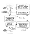
- RNAA response is positive, the program then enters block 140 (Fig. 5B).
- block 140 the program sets up control blocks. From block 140 the program next descends into block 142.
- block 142 the program performs the following function. It replaces the OLU address in the send CDINIT with the alias address received in the RNAA response. It enters the DLU alias address for the network of the OLU in the appropriate control blocks.
- the program then descends into block 144 where it sends cross domain initiate (CDINIT) to the next adjacent active SSCP.
- the program then descends into block 146 where it receives a positive or negative response from the request send in block 144.
- the program then descends into decisional block 148.
- the program checks to see if the CDINIT response is negative or positive. If it is negative, the program enters block 150. In block 150 the program resets the control block which was set up in blocks 140 and 142. The program also notifies the gateway node of the session failure. If the response is positive, the program descends into block 152 (Fig. 5C).
- the program saves the real address in the appropriate control blocks set up by blocks 140 and 142 to complete the gateway SSCP's address transformation.
- the program then descends into block 154 where it sends the commands containing path information, DLU real address, etc. to the gateway node.
- the program then descends into block 156 where it prepares a CDINT response.
- the program makes the address translation specified in block 156 and then sends the response prepared by block 156 to the SSCP of the originating LU (block 158).
- the program then descends to block 160 where it exits.
- the gateway SSCP now has the complete address transformed and the address contained in the SSCP-SSCP request will be translated utilizing the information contained in the control blocks built by the above CDINIT processing.
- the gateway node also has a complete address transformed, and the addresses contained in the transmission headers associated with this session will be transformed utilizing control blocks built by the RNAA processing.
- Figs. 6A-6B show an algorithm used to interconnect networks when both the address and name alias functions are used.
- Common blocks in Figs. 5 and 6 are identified by common numerals. The common blocks perform identical functions. Because the identical functions have already been described, only those blocks which perform new functions to implement the name aliasing function will be described.
- the crux of the name aliasing is that each network uses an alias name to identify resources in another network. By using alias names the same name can be used to identify logical units in separately controlled networks. However, when these networks are connected via the network interconnect function of the present invention, there is no need to assign new names to the resource. Instead, a unique alias name is used in the address space of each of the attached networks, and it is the duty of the gateway SSCP to make the proper name translation during the establishment of a session between two LUs.
- the program includes the names as known in the network on the DLU side of the gateway in the CDINIT.
- the gateway SSCP sends the real name transformed to the gateway NCP.
- Fig. 8 shows an alternative approach for representing the steps which must be performed in the gateway SSCP and the gateway node in order to effectuate the network interconnect function.
- LU 1 Network A
- LU 2 Network B
- the square blocks on the top of the page represent the various components. Naming the blocks from left to right, LU 1 represents a resource in network A, SSCP 1 represents the control point for network A, the gateway SSCP and gateway node represent the interconnect device of the present invention and SSCP 2 and LU 2 represent the control point and logical unit, respectively, in network B.
- the representation in Fig. 8 is often referred to as a flow diagram in contrast to the flow chart of Figs. 5A through 6C.
- the command INITIATE flows from the logical unit (LU 1) to its own SSCP 1.
- the INITIATE commands indicate that (LU 1) request a session with a resource named (LUX).
- the real name of the LU that LU 1 wants to enter into session with is LU 2.
- network A already has a logical unit by the name of LU 2 (not shown). Therefore, LU 2 is known with the alias name LUX in network A.
- step 172 is followed by steps 174, 176 and so on.
- Other commands which are represented in Fig. 8 and were not previously described are the "Bind" flow.
- This flow is issued when an LU is ready to go into session with another LU.
- the "Bind” carries information peculiar to each LU.
- the session starting flow is prepared and sent by an LU to its controlling SSCP.
- the cross domain commands are generated and are sent between SSCPs.
- the SSCP 1 sends a cross domain initiate request (CDINIT) to the SSCP specified in its table as the owner of LUX which in this case is the gateway SSCP.
- the cross domain initiate includes a mode name, the class of service name, the name of LU 1, the address of LU 1, and the name LUX. Since the gateway SSCP has no definition of LUX, it uses a name translation function and determines that LUX corresponds to LU 2 in network B owned by SSCP 2. Using the destination network identifier the name translation tables are also searched to find the alias name used in the network B for LU 1, the class of service name in network B, and the mode name in network B. All of this information is returned to the gateway SSCP.
- the gateway SSCP knows the requested logical unit is in another network.
- the gateway SSCP sends a request network address assignment (RNAA) command asking the gateway node to allocate a pair of alias addresses for the session.
- the network identifiers and names of the logical units are included in the RNAA, along with the network address of LU 1.
- the gateway node assigns an address in network A to represent LU 2 and an address network to represent LU 1. These alias addresses are returned in response to the RNAA.
- the gateway SSCP Before sending CDINIT to SSCP 2, the gateway SSCP changes the name fields to carry the mode, class of service, original LU, and destination LU names understood in the name space of network B.
- the original LU address is changed to the alias address assigned for LU 1 in the network B sub-area of the gateway node.
- CDINIT passes through the gateway node, one of the transmission headers is changed to represent the gateway SSCP to SSCP 2 session in network B.
- SSCP 2 processes the CDINIT as the owner of LU 2 and returns the address of LU 2 in the response.
- the gateway SSCP After receiving the response to CDINIT, the gateway SSCP has all the information required to complete the transform of the gateway node.
- the network address of LU 2 in network B from the response completes the address mapping started with RNAA.
- Both alias and real names of the two logical units are known from CDINIT and the name translation tables and the class of service name in network A resolves to the list of virtual routes for the session path between the gateway node and LU 1. This list is needed when BIND from the primary LU arrives at the gateway node.
- a set control vector request gives the address of LU 2,_ the LU name transform, and the virtual route list of the gateway node. All of this information is used by the gateway node when it receives BIND.
- the gateway SSCP Before forwarding the send initiate response to SSCP 1, the gateway SSCP changes the destination LU address field to carry the alias address for LU 2 in the network sub-area of the gateway node.
- the class of service name field carries the name that applies in network A.
- SSCP 1 handles the response as for a cross domain session. It sends a response to LU 1 for the original initiate, resolves the mode name session parameters, and sends the session parameters to the other SSCP in cross-domain control initiate (CDCINIT).
- the rest of the session setup sequence is just a matter of rerouting requests to the gateway SSCP after translating name and address fields, as needed, and changing transmission headers in the gateway node.
- the virtual route list sent on the SET CV request is used to select and activate a route from the gateway node to the sub-area node for LU 1.
- the same request used by host node to activate routes for use by the gateway node before BIND is sent to LU 1, and the logical unit name field is in the BIND or change to carry the name understood by LU 1.
- the primary LU name is changed from LU 2 if a negotiable BIND is used to allow the secondary LU to return suggested BIND parameters to the primer LU, the gateway node does a reverse translation of LU names in the BIND response. This ends the description of the invention.
- the present invention is implemented in the gateway node and the gateway SSCP, there is no limitation in the architecture that would prevent it from implementation in a single device, be it a communication controller or a host computer.
Abstract
Description
- The present invention relates to computer network systems in general and more particularly to the management of a multiple-network system.
- The use of computer network systems for processing and transmitting data is well known in the prior art. A typical computer network system consists of at least one host computer running under some type of operating system, communication controllers, a communication medium and a plurality of end users (terminals, printers, displays, etc.). The host computer is connected, via a channel, to a first set of the communication controllers. The communication controller interfaces with the communication medium. The communication medium may be telephone lines, satellites, etc. A second set of communication controllers is connected to the communication medium and is connected by one or more device controllers to the end user devices. By entering a request at a user terminal, a user may extract data from the host computer.
- In addition to the physical structure, the prior art computing systems are controlled by a system architecture which ensures the orderly flow of information throughout the system. The prior art describes several types of architectures. For example, an overview of the architecture used in computer networks is given in an article entitled, "Computer Network Architecture," by S. Wecker in Computer, September 1979. Another overview, including a description of System Network Architecture (SNA) is given in an article entitled, "An Introduction to Network Architectures and Protocols," by P. E. Green and printed in the IBM System Journal, Vol. 18, No. 2, 1979. In these articles, the various computer networks such as SNA, DMA, ARPANET, etc. are described by means of hierarchical architectural layers, where the lowest layer relates to the physical communication lines interconnecting various user nodes of the network and where the highest level concerns the conversation per se between the various end users of the network.
- In an attempt to standardize network architecture, the International Organization for Standardization (ISO) has adopted a model which is described by Herbert Zimmerman in an article entitled, "OSI Reference Model - the ISO Model of Architecture for Open Systems Interconnections," IEEE Transactions on Communications, April 1980. The model architecture consists of seven layers, namely: physical, data link, network, transport, sessions, presentation and application layers. The present invention mainly concerns the session layer which relates to the establishment, termination and control of sessions between two end users.
- In order to enable resources in one network to communicate with resources in another network, the prior art utilizes a facility called a gateway for interconnecting the networks. For example, the International Telephone and Telegraph Consultant Committee (CCITT) in an article entitled, "Recommendations X.75 and X.121 of CCITT," 1980 Plenary of the International Telephone and Telegraph Consultant Committee, has defined an interface (X.75) for interconnecting public data network that offers an X.25 user interface. This approach uses a global addressing scheme (X.121) that is apparent at the user interface in each network.
- In another prior art approach, the Advance Research Projects Agency (ARPA) interconnects networks using the ARPA-specified virtual call protocol between gateways and routes datagrams from gateway to gateway as local network packets that include a global network address for the destination. A more detailed description of this approach is given in the following articles: C. Sunshine, "Current Trends in Network Computer Network Interconnection," Eurocomp 78; Proceedings of the European Computer Congress, London, England, May 9-12, 1978, On-Line Conference Ltd., Uxbridge, England (1978), pp. 465-472, and F. A. Tobagi, "Multi-Access Protocols in Packet Communication Systems," IEEE Transaction on Communications Com-28, No. 4, 468-488 (April 1980).
- Although the above interconnecting gateways work well for their intended purpose, implementation appears to be cumbersome and difficult. It is believed that this drawback stems from the fact that a global address scheme is used. This makes it difficult to use the prior art gateway to interconnect existing independently controlled networks. The use of a global address suggests that all previously assigned addresses have to be redefined to eliminate possible conflicts. As the use of computer networks increases, the desirability for a more efficient approach to interconnect networks will inevitably increase.
- It is a general object of the present invention to provide a more efficient method for interconnecting networks.
- It is another object of the present invention to interconnect pre-existing networks without interrupting pre-existing controls.
- This and other objects are achieved by providing a programmable interface apparatus for interconnecting a plurality of independently controlled networks to enable an addressable resource in one network to communicate with an addressable resource in another network, said programmable apparatus comprising:
- means including the addressable resource, operable for generating a first session service initiate request, said request including an address for the originating resource, a name for the originating resource, and a name for the destination resource;
- means responsive to the first initiate request and operable for determining the address of the destination resource and for preparing a second initiate request message including the address of the destination resource and forwarding said second initiate request;
- means operable for receiving the second initiate request and for performing an address translation in said second initiate request and for routing said second request to the proper destination resource whereby the networks are being interconnected without merging.
- The invention also provides a method for interconnecting independently controlled computer networks so that logical units in one network can communicate with logical units in another network; said method comprising the following steps:
- providing an address translation function;
- preparing and forwarding a session initiate request message; said message including an address field with the name of an originating logical unit, a name field with the name of an originating logical unit, and a second name field with the name of the destination logical unit;
- buffering the session initiate request message;
- utilizing the address translation function to derive a set of addresses;
- substituting the addresses in the initiate request and forwarding the request as a result of which a session is being established between the logical units in each network.
- The invention also provides a computer telecommunication network system having a plurality of independently controlled networks with each network having at least one host computer controlling a plurality of addressable resources, an apparatus for interconnecting the networks so that addressable resources in one network can communicate with resources in another network, said apparatus comprising:
- means, including the addressable resource, operable for generating a session service request command message, said command message having an address field and a name field for an originating resource and a name field for a destination resource;
- means responsive to said command and operable to make appropriate name and/or address translations and to route the command messages to the network containing the destination resource with said message resulting in a session being established with the session carrying messages between the originating resource and destination resource; and
- means operable to intercept the messages and for changing the addres header so that the messages are being delivered without changing the characteristics of the independently controlled networks.
- The foregoing features and advantages of the invention will be more fully described in the accompanying drawings.
-
- Fig. 1 is a block diagram showing the components of the gateway according to the present invention.
- Fig. 2 shows a block diagram of a computer network system. The host computer and the communications controller are similar to the components of Fig. 1.
- Fig. 3 shows a format for the Path Information Unit (PIU).
- Fig. 4 shows a flow chart for an algorithm used by an SSCP to process initiate request for an LU in its own domain.
- Figs. 5A-5C show a flow chart for an algorithm used in implementing the network interconnect function. This flow chart involves an address translation function only.
- Figs. 6A-6B show a flow chart for implementing the invention with the address translation and name translation function.
- Fig. 7 shows a more detailed block diagram of the components used to provide the network interconnect function.
- Fig. 8 shows an alternate way for representing the invention.
- Although the present invention is not restricted to any specific type of computer network, it works well with the IBM SNA network which uses the SNA architecture and protocol and as such will be described in that environment. However, this should not be construed as a limitation on the scope of the present invention since it is within the skill of one skilled in the computing art to use the invention as is disclosed or with slight modification to interconnect networks other than the IBM SNA network.
- A typical SNA network is described in the IBM manual, "Advanced Communication Functions for Virtual Telecommunications Access Methods," GC27-0463-2, February 1981. The SNA network utilizes the system network architecture (SNA) to allow terminals, application programs and other logical resources to communicate with one another using SNA entities called logical units. A more detailed description of the architecture and network is given in the referenced manual and is incorporated herein by reference.
- Fig. 1 is a conceptual representation of the present invention. The invention is comprised of a gateway node interconnecting network A and network B. The gateway node is placed on the boundaries of the two networks. It should be noted that although Fig. 1 shows the interconnection of two networks the showing is only symbolic and does not limit the number of networks which the invention can interconnect. In essence, the node may be used to interconnect as many as 255 separate networks. The gateway includes a gateway SSCP identified by
numeral 10 and a gateway node identified bynumeral 12. A channel identified by numeral 14 interconnects thegateway SSCP 10 to thegateway node 12. Alternatively, an SNA link could have been used to connect the gateway SSCP to the gateway node. The gateway SSCP can be any conventional host computer. In the preferred embodiment of this invention thegateway SSCP 10 is an IBM System 370 class processor. The structure and instruction set of this computer is well known in the prior art and as such the details will not be given. A description of the IBM 370 class processors is given in "Microprogramming Principles and Practices" by Samir S. Husson (Prentice Hall, 1970), "Advanced Communication Function for a Network Control Program for IBM 3725 and IBM 3705....," (GC30-3071 and GC30-3058), and "General Information for Virtual Telecommunication Access Method" (GC27-0463 and GC27-0462). The cited literature is incorporated herein by reference. - Similarly, the gateway node can be any conventional communication controller. The preferred embodiment of this invention, the gateway node, is the IBM 3705 and/or 3725 communication controller. The details of this controller are well known in the prior art and will not be given. Suffice it to say that the controllers uses the UC1 processor and a detailed description is given in the above-referenced manual.
- Each of the networks A and B is managed and controlled as separate entities. To this end, network A is fitted with at least one SSCP identified by
numeral 16. The SSCP is the control point for a plurality of addressable units, only one of which is shown in network A and identified asLU 18. Similarly, network B is provided withSSCP 20 andLU 22.LU 18 is located in the domain ofSSCP 16. Likewise,LU 22 is located in the domain ofSSCP 20. Communication across network boundaries is hereinafter referred to as internetwork communication. Communication within a network boundary is referred to as intranetwork communication. For intranetwork communication an LU such asLU 18 or LU 22 generates and transmits a session initiation request toSSCP 16 andSSCP 20 overlogical communication routes - It is assumed that
LU 18 wants to communicate withLU 22. Both LUs are in separately controlled networks. The invention allows such a communication without affecting the configuration and management of either network. The procedure for such an interconnection is that a session has to be established betweenLU 18 andLU 22. Once the session is established, messages can flow freely on the session. The session establishment begins withLU 18 preparing and transmitting an initiation request (to be described later) toSSCP 16.SSCP 16 receives and interprets the message. After interpretation,SSCP 16 determines thatLU 22 is not in its domain.SSCP 16 prepares and transmits a cross domain session initiation request togateway SSCP 10. Thegateway SSCP 10 generates and exchanges a set of control messages between the gateway node and itself. As a result of these messages, an address transform is established in the gateway node. In other words, the address ofLU 22 is placed in the address field. Similarly, routing information, and name translation are performed bySSCP 10. The gateway node changes the address in the transmission header (to be described hereinafter) and as a result a session is established betweenLU 18 andLU 22. The broken line identified bynumeral 28 is a logical representation of the session. Once the session is established, messages flowing betweenLU 18 andLU 22 pass throughgateway node 12 where the address translation in the transmission header is performed. It should be noted that thegateway SSCP 10 together with thegateway node 12 also participates in the establishment and discontinuation of sessions. However, actual message flow between the LUs involves the gateway node only. - Fig. 2 shows a detailed schematic of network A and network B. Since both networks are substantially the same, the details are given for network A only with a skeleton showing to represent the components of network B. In order to simplify the description, the gateway of Fig. 1 is shown as a single box. In actuality and as shown in Fig. 1, the GWN node would be composed of several components. The computer networks include a
host processor 1 located in network A and a host processor 9 located in network B. The host processors may be any conventional host computer. In the preferred embodiment of this invention, the host computers are IBM System 370. These host computers are identical to the host computer used as the gateway SSCP. Thehost processor 1 includes anoperating system 17, a plurality ofapplication programs 13, and a virtual telecommunication access method (VTAM) 12. VTAM contains a system service control point (SSCP)component 14. VTAM is an IBM communication access method which is well known and as such details will not be given. Suffice it to say that the system services controlpoint 14 is a component of VTAM that manages the network. The SSCP performs functions such as bringing up the network and shutting it down, assisting in establishing and terminating the communication between network addressable units (intranetwork session) and reacting to network problems, such as failure of a link or control unit. To perform these functions, the SSCP must be able to communication with physical units PU and logical units LU in its own domain. A more detailed description of VTAM/SSCP is given in the above referenced manuals. - Still referring to Fig. 2, a
communication controller 2 is attached to thehost 1 via achannel 16, and a local cluster controller 4 is attached over a channel 15 to the host. Thecommunication controller 2 is a transmission control unit with processing controlled by advanced communications function (ACF) network control program (NCP) that resides in its storage. The ACF/NCP is well known to those skilled in the art, and as such details will not be given,. Suffice it to say the main purpose of the network control program is to transmit data received from thehost processor 1 to terminals, clusters, or other NCPs and to receive data from the terminals, clusters, or other NCPs, and sends it to the host. The NCP can process the data in various ways as it passes through the controller. In controlling the flow of data, the NCP must interact with portions of the controller hardware. On the line side, the NCP interacts with the communications scanner and on the channel side it interacts with the channel adapter. A more detailed description of the communication controller and its associated control program is given in the above referenced manual. - The
communication controller 2 is connected to aremote cluster controller 5 over a synchronous data link control (SDLC) link 21. Thecommunication controller 2 is also connected over alink 25 to a remote communication controller 6 and by means of links 22'-24' toterminals communication controller 2 with aremote communication controller 11 in network B. In the network B there is also shown acommunication controller 10 connected between the host processor 9 and theremote communication controller 11. It should be noted that thecommunication controller 2 and its control program are substantially the same as the gateway node. - Each element, in the network of Fig. 2, that can send or receive data is assigned a network address and is known as a network addressable unit (NAU). The network address uniquely identifies the element, regardless of whether the element is a device such as a terminal or terminal control unit, program such as an application program in a cluster controller or in a host processor, or a portion of an access method, such as VTAM. The network address contains information necessary to route data to its destination. SNA defines three types of network addressable units, namely: system services control point (SSCP), physical units (PU) and logical units (LU).
- A physical unit (PU) is represented in Fig. 2 as an encircled PU. It is a portion of a device, usually programming or circuitry or both, that performs control functions for the device in which it is located and, in some cases, for other devices that are attached to the device that contains the PU. For the devices under its control the physical unit takes action during activation and at deactivation during error recovery and resetting synchronization, during testing, and during gathering of statistics on operation of the device. Each device in the network is associated with a physical unit. In the local cluster controller 4 there is a
physical unit 41 and in theremote cluster control 5 there is aphysical unit 51. There are also physical units in thelocal communication controller 2 and in the remote communication control 6. - A logical unit (LU) is a device or program by which an end user, a terminal operator, and or an input/output mechanism gains access to the network. The logical unit can be built in logic or programming associated with the terminal's sub-system stand-alone device, or an application program. As far as the network is concerned, a logical unit (LU) is an access port into the network. The logical unit may or may not be the original source. The contents of the request of the information on which the request is based may have originated at the device controlled by the logical unit. Similarly, the network sees a logical unit as a destination of a request (RU) unit. In Fig. 2 a logical unit is shown as an encircled LU. In the
host processor 1 there are shown a plurality of application programlogical units 13. In the local cluster controller 4, there are two logical units 42' and 43 controlling the devices 44' and 45. Thecluster controller 5 contains logical units 52-54 controlling devices on loops 55-57. Each of the terminals 31-33 comprises of PUs 34-36 and LUs 37-39. - Fig. 3 shows the format for the basic information unit which flows between the nodes in the network. The format includes a link header (LH) 91, a transmission header (TH) 92, a request-response unit (RU) 94, and a link trailer (LT) 95. The request-response header and the request-response adder forms the basic information unit (BIU). The base information unit combines with the transmission header to form the path information unit (PIU). Finally, the path information unit combines with the link header to form the basic link unit. A basic link unit may include one or more PIUs. It should be noted that as the basic information unit travels through the various SNA levels the additional units are added. The basic information unit is the unit that travels from one end user node to another end user node in the network. The transmission header contains information which guides the BIU through the network. The transmission header comprises address information and other necessary information for transmission control. The link header and link trailer are added to the PIU to control the transmission of a PIU over a link.
- As will be explained subsequently, in order to implement the network interconnect function of the present invention, VTAM amd NCP are enhanced with software to form the gateway SSCP and gateway node. These enhanced devices translate information in the RU and RH fields of messages. As a result of these translations, the message is conveyed to an end user.
- Fig. 7 shows a more detailed block diagram of the components which are needed to effectuate the network interconnection function. Elements in Fig. 6 that are common with elements in Fig. 1 are identified with identical numerals.
- Since the common elements have already been described, this description will be limited to new elements only. New elements which are added in Fig. 7 are identified and their functions are described. Each of the networks connected by the gateway is assigned an address space in the gateway node.
- To this end, address space A identifies the address space for network B in
gateway node 12. Similarly, address space B defines the address space for network B in the gateway node. The function of the address space is to contain alias addresses and/or names of the LU that are connected to the gateway node. Address space A contains the alias addresses and/or alias names used in network A to identify LUs of network B. Similarly, address space B contains the alias addresses and/or alias names used in network B to identify logic units (LU) in network A. Essentially, the addresses and/or names are maintained in a table look-up which is controlled by a modified NCP (details will be given subsequently). Each address space in the gateway node has a pool of network address facilities (NAF) control blocks (not shown) that can be assigned to an SSCP or LU for cross-network sessions. Associated with each NAF block there are a number of half session control blocks (HSCB) representing sessions involving the represented LU or SSCP. By way of example, an entry for an LU in network B would be recorded in address space A as follows: the NAF block would contain the alias name for the LU of network B and its real name. The HSCB block would contain the real name and address of the LU in network A. The entry in the address space B for an LU in network A would be similarly recorded. As will be explained subsequently, the NCP (network control program resource facility), which controls the gateway node, would fill in the various control blocks and as a session traverses the gateway node the address in the transmission header is transformed using the same programming facility. - Still referring to Fig. 7, the
gateway SSCP 10 is enhanced by the address and name translation means identified bynumeral 100. Essentially, the address and name translation means 100 include a plurality of software developed tables which has the real address and names of addressable resources (LU and/or PU) in remote networks. TheSSCP 16 is enhanced with anentry 102 in itsaddress space 104.Address space 104 is a table which contains the addresses of all the resource LUs, etc., that are in the domain of SSCP 6. SSCP 6 may allow a session between the resources in its domain. The contents ofentry 102 is an address for thegateway SSCP 10. Theentry 102 is used to establish a cross domain initiate request (CDINIT). Similarly,element 106 is implemented in theaddress space 108.Address element 106 is utilized to initiate a CDINIT request when addressable unit (LU and/or PU) in network B needs to be interconnected with an LU in network A. - Before describing the flow charts of the algorithm which is used to implement the network interconnect function, a summary of the primary request units which are used to implement the function will be given. SNA utilizes the initiate (INIT), cross domain initiate (CDINIT), response cross domain initiate (RSP-CDINIT), request network address assignment (RNAA), response request network address assignment (RSP-RNAA), and set control vector (SETCV) commands to establish a session between LUs in separately controlled networks.
- The INIT when used in the most general case requests a session initiation between any two named LUs.
- CDINIT is used when the receiver of the INIT is not the owner of both LUs and contains the origin LU name, origin LU address and destination LU (DLU) name.
- RSP-CDINIT is used to indicate that the requested session is authorized and contains the assigned DLU address for this session instance.
- RNAA is used between the gateway SSCP and the gateway node to request alias address assignments for a particular session.
- SETCV is used to send control information such as path to be activated for a particular session and the name transform from the gateway SSCP to the gateway node.
- Fig. 4 shows a flow chart defining the process steps which are performed by an SSCP such as
SSCP 16 or 20 (Fig. 1) for processing and initiate requests from an LU within its own domain. The first step of the process is shown inblock 110. The initiate request is generated and transmitted by an LU. The SSCP receives the initiation request. The program then descends intoblock 112.Block 112 is a decisional block and checks to see if the name of the destination LU is in the domain of the SSCP. If it is, the program moves intoblock 114 where it performs normal SSCP processing. This type of processing does not form part of the present invention and as such the details will not be given. However, if such detail is required, then see ACP/VTAM Programming Manual SC27-0611. - If the LU name is not in the domain of the SSCP, the program descends into
block 116.Block 116 is a decisional block and the program checks to see if either LU is in its own domain. If none of the LUs are in the domain, the SSCP sends or initiates other cross domain messages to the SSCP owning the destination LU (block 118). If the destination LU is in the domain of the SSCP, the SSCP then builds and sends a CDINIT request (block 120) to the gateway SSCP. - Figs. 5A through 5C show the algorithm which is processed in the gateway to effectuate the network interconnect function. The process steps which the program performs are summarized in the respective blocks. In order to simplify the description, only a brief summary of the process steps is given, it being understood that the flow charts can be consulted for a more detailed description of the process steps. The cross domain initiate request which is prepared and transmitted from an SSCP in a network is received in the gateway SSCP.
- To this end, block 121 represents the first step in the program and the gateway SSCP receives the CDINIT request. As described above, the format of the request is similar to that shown in Fig. 3 and the minimum information includes the OLU name and address and the DLU name. The program next descends into
decisional block 122. Indecisional block 122 the program checks to see if the named DLU is in its own domain. If it is, the program entersfunction block 124. If the SSCP receiving the cross domain initiate request is owner of the DLU, the SSCP then performs normal SSCP processing. The receiving SSCP determines whether or not it owns a resource (DLU) by interrogating its own internal tables. - If the DLU is not in its own domain, the program then descends into
decisional block 126. Inblock 126 the program checks to see if the DLU is in an active domain. If it is not, the program enters block 128 wherein it rejects the CDINIT and the session setup fails. If the DLU is in an adjacent active domain, the gateway SSCP sends the RNAA command to the gateway node (block 130). The gateway SSCP uses the RNAA command to ask the gateway node for alias addresses for the OLU in the network of the DLU and an alias address for the DLU in the network of the OLU. As discussed above, this information is contained in tables that are stationed in the address space for network A and network B, respectively. After the RNAA response is received from the gateway node, block 132, the gateway SSCP viablock 134 checks to see if the RNAA response is positive or negative. If the response is negative, the program entersblock 136. The negative response indicates that the gateway node was unable to assign an alias address. Fromblock 136 the program descends intoblock 138 where it exits the program. - If the RNAA response is positive, the program then enters block 140 (Fig. 5B). In
block 140 the program sets up control blocks. Fromblock 140 the program next descends intoblock 142. Inblock 142 the program performs the following function. It replaces the OLU address in the send CDINIT with the alias address received in the RNAA response. It enters the DLU alias address for the network of the OLU in the appropriate control blocks. The program then descends intoblock 144 where it sends cross domain initiate (CDINIT) to the next adjacent active SSCP. The program then descends intoblock 146 where it receives a positive or negative response from the request send inblock 144. The program then descends intodecisional block 148. The program checks to see if the CDINIT response is negative or positive. If it is negative, the program entersblock 150. Inblock 150 the program resets the control block which was set up inblocks - In
block 152 the program saves the real address in the appropriate control blocks set up byblocks block 154 where it sends the commands containing path information, DLU real address, etc. to the gateway node. The program then descends intoblock 156 where it prepares a CDINT response. The program makes the address translation specified inblock 156 and then sends the response prepared byblock 156 to the SSCP of the originating LU (block 158). The program then descends to block 160 where it exits. - At the instant of exit the gateway SSCP now has the complete address transformed and the address contained in the SSCP-SSCP request will be translated utilizing the information contained in the control blocks built by the above CDINIT processing. Likewise, the gateway node also has a complete address transformed, and the addresses contained in the transmission headers associated with this session will be transformed utilizing control blocks built by the RNAA processing.
- Figs. 6A-6B show an algorithm used to interconnect networks when both the address and name alias functions are used. Common blocks in Figs. 5 and 6 are identified by common numerals. The common blocks perform identical functions. Because the identical functions have already been described, only those blocks which perform new functions to implement the name aliasing function will be described. The crux of the name aliasing is that each network uses an alias name to identify resources in another network. By using alias names the same name can be used to identify logical units in separately controlled networks. However, when these networks are connected via the network interconnect function of the present invention, there is no need to assign new names to the resource. Instead, a unique alias name is used in the address space of each of the attached networks, and it is the duty of the gateway SSCP to make the proper name translation during the establishment of a session between two LUs.
- The new blocks in Figs. 6A-6C which implement the name translation functions are
blocks block 162, the program derives the names as known on the DLU side of the gateway node. The names are recorded in the gateway SSCP and by way of a table look-up the gateway SSCP can derive the appropriate name. - In
block 164 the program includes the names as known in the network on the DLU side of the gateway in the CDINIT. - In
block 168 the gateway SSCP sends the real name transformed to the gateway NCP. - In
block 170 the program sets the destination LU (DLU) in the CDINIT response to the DLU alias address received from the gateway node in the RNAA response which had been saved inblock 164. - Fig. 8 shows an alternative approach for representing the steps which must be performed in the gateway SSCP and the gateway node in order to effectuate the network interconnect function. In the figure it is assumed that two networks will be interconnected. However, the invention is intended to interconnect more than two networks. It is also assumed that LU 1 (Network A) wishes to enter into a session with LU 2 (Network B). The square blocks on the top of the page represent the various components. Naming the blocks from left to right,
LU 1 represents a resource in network A,SSCP 1 represents the control point for network A, the gateway SSCP and gateway node represent the interconnect device of the present invention andSSCP 2 andLU 2 represent the control point and logical unit, respectively, in network B. The representation in Fig. 8 is often referred to as a flow diagram in contrast to the flow chart of Figs. 5A through 6C. - The directions in which the messages flow are indicated by the arrowheads. For example, the command INITIATE (LUX) flows from the logical unit (LU 1) to its
own SSCP 1. As before, the INITIATE commands indicate that (LU 1) request a session with a resource named (LUX). The real name of the LU thatLU 1 wants to enter into session with isLU 2. However, network A already has a logical unit by the name of LU 2 (not shown). Therefore,LU 2 is known with the alias name LUX in network A. - The order of the flow is sequential. This means that
step 172 is followed bysteps - The rest of the flow is self-explanatory, and a detailed description of each flow will not be given. Suffice it to say that the
SSCP 1 sends a cross domain initiate request (CDINIT) to the SSCP specified in its table as the owner of LUX which in this case is the gateway SSCP. The cross domain initiate includes a mode name, the class of service name, the name ofLU 1, the address ofLU 1, and the name LUX. Since the gateway SSCP has no definition of LUX, it uses a name translation function and determines that LUX corresponds toLU 2 in network B owned bySSCP 2. Using the destination network identifier the name translation tables are also searched to find the alias name used in the network B forLU 1, the class of service name in network B, and the mode name in network B. All of this information is returned to the gateway SSCP. - Note that the gateway SSCP knows the requested logical unit is in another network. The gateway SSCP sends a request network address assignment (RNAA) command asking the gateway node to allocate a pair of alias addresses for the session. The network identifiers and names of the logical units are included in the RNAA, along with the network address of
LU 1. The gateway node assigns an address in network A to representLU 2 and an address network to representLU 1. These alias addresses are returned in response to the RNAA. - Before sending CDINIT to
SSCP 2, the gateway SSCP changes the name fields to carry the mode, class of service, original LU, and destination LU names understood in the name space of network B. The original LU address is changed to the alias address assigned forLU 1 in the network B sub-area of the gateway node. As CDINIT passes through the gateway node, one of the transmission headers is changed to represent the gateway SSCP toSSCP 2 session innetwork B. SSCP 2 processes the CDINIT as the owner ofLU 2 and returns the address ofLU 2 in the response. - After receiving the response to CDINIT, the gateway SSCP has all the information required to complete the transform of the gateway node. The network address of
LU 2 in network B from the response completes the address mapping started with RNAA. Both alias and real names of the two logical units are known from CDINIT and the name translation tables and the class of service name in network A resolves to the list of virtual routes for the session path between the gateway node andLU 1. This list is needed when BIND from the primary LU arrives at the gateway node. A set control vector request gives the address ofLU 2,_ the LU name transform, and the virtual route list of the gateway node. All of this information is used by the gateway node when it receives BIND. - Before forwarding the send initiate response to
SSCP 1, the gateway SSCP changes the destination LU address field to carry the alias address forLU 2 in the network sub-area of the gateway node. The class of service name field carries the name that applies innetwork A. SSCP 1 handles the response as for a cross domain session. It sends a response toLU 1 for the original initiate, resolves the mode name session parameters, and sends the session parameters to the other SSCP in cross-domain control initiate (CDCINIT). - Except for BIND processing, the rest of the session setup sequence is just a matter of rerouting requests to the gateway SSCP after translating name and address fields, as needed, and changing transmission headers in the gateway node. When BIND arrives at the gateway node, the virtual route list sent on the SET CV request is used to select and activate a route from the gateway node to the sub-area node for
LU 1. The same request used by host node to activate routes for use by the gateway node before BIND is sent toLU 1, and the logical unit name field is in the BIND or change to carry the name understood byLU 1. The primary LU name is changed fromLU 2 if a negotiable BIND is used to allow the secondary LU to return suggested BIND parameters to the primer LU, the gateway node does a reverse translation of LU names in the BIND response. This ends the description of the invention. - Although the present invention is implemented in the gateway node and the gateway SSCP, there is no limitation in the architecture that would prevent it from implementation in a single device, be it a communication controller or a host computer.
Claims (17)
Applications Claiming Priority (2)
| Application Number | Priority Date | Filing Date | Title |
|---|---|---|---|
| US551449 | 1983-11-14 | ||
| US06/551,449 US4677588A (en) | 1983-11-14 | 1983-11-14 | Network interconnection without integration |
Publications (3)
| Publication Number | Publication Date |
|---|---|
| EP0142004A2 true EP0142004A2 (en) | 1985-05-22 |
| EP0142004A3 EP0142004A3 (en) | 1987-10-14 |
| EP0142004B1 EP0142004B1 (en) | 1991-01-02 |
Family
ID=24201317
Family Applications (1)
| Application Number | Title | Priority Date | Filing Date |
|---|---|---|---|
| EP84111870A Expired EP0142004B1 (en) | 1983-11-14 | 1984-10-04 | Method and apparatus for interconnecting independent networks |
Country Status (4)
| Country | Link |
|---|---|
| US (1) | US4677588A (en) |
| EP (1) | EP0142004B1 (en) |
| JP (1) | JPS60108950A (en) |
| DE (1) | DE3483819D1 (en) |
Cited By (6)
| Publication number | Priority date | Publication date | Assignee | Title |
|---|---|---|---|---|
| EP0289248A2 (en) * | 1987-05-01 | 1988-11-02 | AT&T Corp. | Programmable protocol engine |
| WO1993005599A1 (en) * | 1991-09-10 | 1993-03-18 | Telefonaktiebolaget Lm Ericsson | Communication equipment control system and method |
| GB2284326A (en) * | 1993-11-24 | 1995-05-31 | Ericsson Ge Mobile Communicat | Interconnection of multisite switch controlled networks |
| WO1998051092A1 (en) * | 1997-05-06 | 1998-11-12 | Telefonaktiebolaget Lm Ericsson (Publ) | Computer telephony integration gateway |
| US5995610A (en) * | 1997-05-06 | 1999-11-30 | Telefonaktiebolaget Lm Ericsson | Cooperative call processing across public and private intelligent networks |
| US6044142A (en) * | 1997-05-06 | 2000-03-28 | Telefonaktiebolaget L M Ericsson | Method and arrangement for integrating intelligent network services with operator assisted services |
Families Citing this family (92)
| Publication number | Priority date | Publication date | Assignee | Title |
|---|---|---|---|---|
| USRE33181E (en) * | 1981-02-03 | 1990-03-13 | Hitachi, Ltd. | Data transmission system adapted to facilitate detection of safe receipt of a transmitted data frame by a receiving station |
| US5228127A (en) * | 1985-06-24 | 1993-07-13 | Fujitsu Limited | Clustered multiprocessor system with global controller connected to each cluster memory control unit for directing order from processor to different cluster processors |
| US5230048A (en) * | 1986-09-03 | 1993-07-20 | Wang Laboratories, Inc. | Data processing system with tree and list data structure |
| US5165018A (en) * | 1987-01-05 | 1992-11-17 | Motorola, Inc. | Self-configuration of nodes in a distributed message-based operating system |
| US5060150A (en) * | 1987-01-05 | 1991-10-22 | Motorola, Inc. | Process creation and termination monitors for use in a distributed message-based operating system |
| US5165020A (en) * | 1987-03-27 | 1992-11-17 | Digital Equipment Corporation | Terminal device session management protocol |
| JPS63278165A (en) * | 1987-05-11 | 1988-11-15 | Fujitsu Ltd | Resource name converting processing system in loose coupling between networks |
| JPS63284660A (en) * | 1987-05-16 | 1988-11-21 | Nec Corp | Inter-processor communication system |
| US4914571A (en) * | 1987-06-15 | 1990-04-03 | International Business Machines Corporation | Locating resources in computer networks |
| US5109483A (en) * | 1987-06-15 | 1992-04-28 | International Business Machines Corp. | Node initiating xid exchanges over an activated link including an exchange of sets of binding signals between nodes for establishing sessions |
| US4989139A (en) * | 1987-07-17 | 1991-01-29 | International Business Machines Corporation | Map case network virtual connection interface system |
| US5109515A (en) * | 1987-09-28 | 1992-04-28 | At&T Bell Laboratories | User and application program transparent resource sharing multiple computer interface architecture with kernel process level transfer of user requested services |
| US4914619A (en) * | 1987-10-19 | 1990-04-03 | International Business Machines Corporation | Apparatus and method for interconnecting an application of a transparent services access facility to remote source |
| US5191651A (en) * | 1987-11-03 | 1993-03-02 | International Business Machines Corporation | Apparatus and method for making of interconnected processors act like a single node in a multinode communication system |
| JPH01130252A (en) * | 1987-11-03 | 1989-05-23 | Internatl Business Mach Corp <Ibm> | Computer assembly connector |
| US5021949A (en) * | 1988-02-29 | 1991-06-04 | International Business Machines Corporation | Method and apparatus for linking an SNA host to a remote SNA host over a packet switched communications network |
| AU601328B2 (en) * | 1988-05-26 | 1990-09-06 | Digital Equipment Corporation | Temporary state preservation for a distributed file service |
| US5345587A (en) * | 1988-09-14 | 1994-09-06 | Digital Equipment Corporation | Extensible entity management system including a dispatching kernel and modules which independently interpret and execute commands |
| DE3832145A1 (en) * | 1988-09-22 | 1990-03-29 | Philips Patentverwaltung | METHOD AND CIRCUIT FOR MEASURING SMALL ELECTRICAL SIGNALS |
| US4974190A (en) * | 1988-12-05 | 1990-11-27 | Digital Equipment Corporation | Pass-through and isolation switch |
| JPH02165241A (en) * | 1988-12-19 | 1990-06-26 | Toshiba Corp | File access system |
| US5142622A (en) * | 1989-01-31 | 1992-08-25 | International Business Machines Corporation | System for interconnecting applications across different networks of data processing systems by mapping protocols across different network domains |
| US5036459A (en) * | 1989-03-09 | 1991-07-30 | U.S. Philips Corporation | Multi-processor computer system with distributed memory and an interprocessor communication mechanism, and method for operating such mechanism |
| US5247520A (en) * | 1989-10-13 | 1993-09-21 | International Business Machines Corporation | Communications architecture interface |
| US5224205A (en) * | 1990-05-21 | 1993-06-29 | International Business Machines Corp. | Method of combining architecturally dissimilar computing networks into a single logical network |
| US5282270A (en) * | 1990-06-06 | 1994-01-25 | Apple Computer, Inc. | Network device location using multicast |
| US5278955A (en) * | 1990-06-18 | 1994-01-11 | International Business Machines Corporation | Open systems mail handling capability in a multi-user environment |
| US5077730A (en) * | 1990-08-02 | 1991-12-31 | Arrowood Andrew H | Method of auditing primary and secondary node communication sessions |
| US5222242A (en) * | 1990-09-28 | 1993-06-22 | International Business Machines Corp. | System for locating a node containing a requested resource and for selectively verifying the presence of the resource at the node |
| US5303238A (en) * | 1990-12-11 | 1994-04-12 | International Business Machines Corporation | Network communications intermediate interface |
| US5023780A (en) * | 1991-01-03 | 1991-06-11 | Northern Telecom Limited | Method of operating a packet switching network |
| US5424724A (en) * | 1991-03-27 | 1995-06-13 | International Business Machines Corporation | Method and apparatus for enhanced electronic mail distribution |
| US5319775A (en) * | 1991-07-22 | 1994-06-07 | Ncr Corporation | Centralized diagnostic system for loosely coupled processors |
| JPH0815277B2 (en) * | 1991-08-09 | 1996-02-14 | インターナショナル・ビジネス・マシーンズ・コーポレイション | System and method for obtaining performance measurements |
| US5371897A (en) * | 1991-08-27 | 1994-12-06 | International Business Machines Corporation | Method for requesting identification of a neighbor node in a data processing I/O system |
| DE69319757T2 (en) * | 1992-01-10 | 1999-04-15 | Digital Equipment Corp | Method for connecting a line card to an address recognition unit |
| DE69330981T2 (en) * | 1992-04-20 | 2002-06-27 | 3Com Corp | Device for expanding network means to remote networks |
| US5671355A (en) * | 1992-06-26 | 1997-09-23 | Predacomm, Inc. | Reconfigurable network interface apparatus and method |
| AU5953394A (en) * | 1992-12-17 | 1994-07-04 | Legent Corporation | System and method for generating local area network operating statistics |
| US6006090A (en) * | 1993-04-28 | 1999-12-21 | Proxim, Inc. | Providing roaming capability for mobile computers in a standard network |
| JP3425192B2 (en) * | 1993-08-25 | 2003-07-07 | 富士通株式会社 | Address information automatic setting processing method and address information setting device |
| US5546549A (en) * | 1994-06-01 | 1996-08-13 | International Business Machines Corporation | Multi-path channel (MPC) interface with user transparent, unbalanced, dynamically alterable computer input/output channels |
| US5633858A (en) * | 1994-07-28 | 1997-05-27 | Accton Technology Corporation | Method and apparatus used in hashing algorithm for reducing conflict probability |
| US5673418A (en) * | 1994-10-07 | 1997-09-30 | Bull Hn Information Systems Inc. | Method and apparatus for emulating the operations of an emulated system terminal driver on a host system |
| US5563878A (en) * | 1995-01-05 | 1996-10-08 | International Business Machines Corporation | Transaction message routing in digital communication networks |
| JP3262689B2 (en) * | 1995-05-19 | 2002-03-04 | 富士通株式会社 | Remote control system |
| US5636371A (en) * | 1995-06-07 | 1997-06-03 | Bull Hn Information Systems Inc. | Virtual network mechanism to access well known port application programs running on a single host system |
| US5764906A (en) * | 1995-11-07 | 1998-06-09 | Netword Llc | Universal electronic resource denotation, request and delivery system |
| US5684800A (en) * | 1995-11-15 | 1997-11-04 | Cabletron Systems, Inc. | Method for establishing restricted broadcast groups in a switched network |
| US6058429A (en) * | 1995-12-08 | 2000-05-02 | Nortel Networks Corporation | Method and apparatus for forwarding traffic between locality attached networks using level 3 addressing information |
| US5987512A (en) * | 1996-06-12 | 1999-11-16 | Sun Microsystems, Inc. | Method and apparatus for access to remote gateway servers |
| JPH1021169A (en) * | 1996-07-02 | 1998-01-23 | Fujitsu Ltd | Communication controller, communication control method of the same and communication system providing the same |
| WO1998009213A1 (en) * | 1996-08-27 | 1998-03-05 | Visual Telesystems, Inc. | Virtualized multimedia connection system |
| US6381650B1 (en) * | 1997-03-10 | 2002-04-30 | Palm, Inc. | Method for finding the address of a workstation assigned a dynamic address |
| ATE367701T1 (en) | 1997-03-12 | 2007-08-15 | Nomadix Inc | NOMADIC TRANSLATOR OR PATH FINDER |
| US5974049A (en) * | 1997-08-29 | 1999-10-26 | International Business Machines Corporation | Internet protocol assists for high performance LAN connections |
| US6185218B1 (en) | 1997-08-29 | 2001-02-06 | International Business Machines Corporation | Communication method and apparatus for use in a computing network environment having high performance LAN connections |
| US6078964A (en) * | 1997-08-29 | 2000-06-20 | International Business Machines Corporation | Establishing direct communications between two hosts without using a high performance LAN connection |
| US5999974A (en) * | 1997-08-29 | 1999-12-07 | International Business Machines Corporation | Internet protocol assists for high performance LAN connections |
| US6006261A (en) * | 1997-08-29 | 1999-12-21 | International Business Machines Corporation | Internet protocol assists using multi-path channel protocol |
| US5987515A (en) * | 1997-08-29 | 1999-11-16 | International Business Machines Corporation | Internet protocol assists using multi-path channel protocol |
| US6023734A (en) * | 1997-08-29 | 2000-02-08 | International Business Corporation | Establishing direct communications between two hosts without using a high performance LAN connection |
| US6003088A (en) * | 1997-08-29 | 1999-12-14 | International Business Machines Corporation | Blocking IP datagrams in a multi-path channel point-to-point environment |
| US6003080A (en) * | 1997-08-29 | 1999-12-14 | International Business Machines Corporation | Internet protocol assists using multi-path channel protocol |
| US6014699A (en) * | 1997-08-29 | 2000-01-11 | International Business Machines Corporation | Internet protocol assists for high performance LAN connections |
| US6084859A (en) * | 1997-08-29 | 2000-07-04 | International Business Machines Corporation | Internet protocol assists using multi-path channel protocol |
| US6009467A (en) * | 1997-08-29 | 1999-12-28 | International Business Machines Corporation | System for checking status of supported functions of communication platforms at preselected intervals in order to allow hosts to obtain updated list of all supported functions |
| AUPO926197A0 (en) * | 1997-09-17 | 1997-10-09 | Bhp Steel (Jla) Pty Limited | Casting steel strip |
| US6151624A (en) * | 1998-02-03 | 2000-11-21 | Realnames Corporation | Navigating network resources based on metadata |
| US6415329B1 (en) * | 1998-03-06 | 2002-07-02 | Massachusetts Institute Of Technology | Method and apparatus for improving efficiency of TCP/IP protocol over high delay-bandwidth network |
| US6154839A (en) * | 1998-04-23 | 2000-11-28 | Vpnet Technologies, Inc. | Translating packet addresses based upon a user identifier |
| US6600743B1 (en) | 1998-08-25 | 2003-07-29 | International Business Machines Corporation | IP multicast interface |
| US6505255B1 (en) | 1999-04-29 | 2003-01-07 | Mitsubishi Electric Information Technology Center America, Inc. (Ita) | Method for formatting and routing data between an external network and an internal network |
| US6490285B2 (en) | 1998-08-25 | 2002-12-03 | International Business Machines Corporation | IP multicast interface |
| US6496862B1 (en) | 1998-08-25 | 2002-12-17 | Mitsubishi Electric Research Laboratories, Inc. | Remote monitoring and control of devices connected to an IEEE 1394 bus via a gateway device |
| US6327621B1 (en) | 1998-08-25 | 2001-12-04 | International Business Machines Corporation | Method for shared multicast interface in a multi-partition environment |
| US6424996B1 (en) * | 1998-11-25 | 2002-07-23 | Nexsys Electronics, Inc. | Medical network system and method for transfer of information |
| US8713641B1 (en) | 1998-12-08 | 2014-04-29 | Nomadix, Inc. | Systems and methods for authorizing, authenticating and accounting users having transparent computer access to a network using a gateway device |
| US8266266B2 (en) | 1998-12-08 | 2012-09-11 | Nomadix, Inc. | Systems and methods for providing dynamic network authorization, authentication and accounting |
| US7028182B1 (en) * | 1999-02-19 | 2006-04-11 | Nexsys Electronics, Inc. | Secure network system and method for transfer of medical information |
| US6378000B1 (en) | 1999-04-29 | 2002-04-23 | Mitsubish Electric Research Laboratories, Inc | Address mapping in home entertainment network |
| US6633547B1 (en) | 1999-04-29 | 2003-10-14 | Mitsubishi Electric Research Laboratories, Inc. | Command and control transfer |
| US6523064B1 (en) | 1999-04-29 | 2003-02-18 | Mitsubishi Electric Research Laboratories, Inc | Network gateway for collecting geographic data information |
| US6738908B1 (en) * | 1999-05-06 | 2004-05-18 | Watchguard Technologies, Inc. | Generalized network security policy templates for implementing similar network security policies across multiple networks |
| US8190708B1 (en) | 1999-10-22 | 2012-05-29 | Nomadix, Inc. | Gateway device having an XML interface and associated method |
| JP2002084326A (en) * | 2001-06-11 | 2002-03-22 | Fujitsu Ltd | Device to be serviced, central unit and servicing device |
| KR100405113B1 (en) * | 2001-06-22 | 2003-11-10 | 주식회사 엑스큐어넷 | Method for implementing transparent gateway or proxy in a network |
| CN1180573C (en) * | 2001-08-29 | 2004-12-15 | 华为技术有限公司 | Pitch point transregional call method in IP network system |
| US6988105B2 (en) * | 2001-09-27 | 2006-01-17 | International Business Machines Corporation | Use of agents and control documents to update a database structure |
| US7389359B2 (en) * | 2001-10-19 | 2008-06-17 | Foundry Networks, Inc. | Method and system for intelligently forwarding multicast packets |
| US8625427B1 (en) | 2009-09-03 | 2014-01-07 | Brocade Communications Systems, Inc. | Multi-path switching with edge-to-edge flow control |
| US11863561B2 (en) * | 2021-11-10 | 2024-01-02 | Oracle International Corporation | Edge attestation for authorization of a computing node in a cloud infrastructure system |
Family Cites Families (7)
| Publication number | Priority date | Publication date | Assignee | Title |
|---|---|---|---|---|
| US3654603A (en) * | 1969-10-31 | 1972-04-04 | Astrodata Inc | Communications exchange |
| JPS5845047B2 (en) * | 1974-03-26 | 1983-10-06 | 株式会社日立製作所 | Information transmission method using common signal transmission path |
| US3949380A (en) * | 1974-04-22 | 1976-04-06 | Honeywell Information Systems, Inc. | Peripheral device reassignment control technique |
| US4155117A (en) * | 1977-07-28 | 1979-05-15 | International Business Machines Corporation | Synchronizing channel-to-channel adapter |
| US4231086A (en) * | 1978-10-31 | 1980-10-28 | Honeywell Information Systems, Inc. | Multiple CPU control system |
| EP0088789B1 (en) * | 1981-09-18 | 1987-08-05 | CHRISTIAN ROVSING A/S af 1984 | Multiprocessor computer system |
| IL66667A (en) * | 1981-10-02 | 1985-06-30 | Hughes Aircraft Co | Method of routing messages between a plurality of data processing units |
-
1983
- 1983-11-14 US US06/551,449 patent/US4677588A/en not_active Expired - Lifetime
-
1984
- 1984-10-04 DE DE8484111870T patent/DE3483819D1/en not_active Expired - Lifetime
- 1984-10-04 EP EP84111870A patent/EP0142004B1/en not_active Expired
- 1984-10-18 JP JP59217510A patent/JPS60108950A/en active Granted
Non-Patent Citations (2)
| Title |
|---|
| C.C.I.T.T., Livre Jaune, part 3, vol. VIII, Avis X.40 to X.180, pages 168,176, Avis X.75, Geneve, CH * |
| PROCEEDINGS OF THE SEVENTEENTH IEEE COMPUTER SOCIETY INTERNATIONAL CONFERENCE COMPCON 78, Washington, D.C., 5th-8th September 1978, pages 72-79, IEEE, New York, US; J.F. SHOCH: "Inter-network naming, addressing, and routing" * |
Cited By (10)
| Publication number | Priority date | Publication date | Assignee | Title |
|---|---|---|---|---|
| EP0289248A2 (en) * | 1987-05-01 | 1988-11-02 | AT&T Corp. | Programmable protocol engine |
| EP0289248A3 (en) * | 1987-05-01 | 1991-02-27 | AT&T Corp. | Programmable protocol engine |
| WO1993005599A1 (en) * | 1991-09-10 | 1993-03-18 | Telefonaktiebolaget Lm Ericsson | Communication equipment control system and method |
| AU681570B2 (en) * | 1991-09-10 | 1997-09-04 | Telefonaktiebolaget Lm Ericsson (Publ) | Communication equipment control system and method |
| GB2284326A (en) * | 1993-11-24 | 1995-05-31 | Ericsson Ge Mobile Communicat | Interconnection of multisite switch controlled networks |
| GB2284326B (en) * | 1993-11-24 | 1998-07-08 | Ericsson Ge Mobile Communicat | Extended trunked RF communications systems networking |
| WO1998051092A1 (en) * | 1997-05-06 | 1998-11-12 | Telefonaktiebolaget Lm Ericsson (Publ) | Computer telephony integration gateway |
| US5995610A (en) * | 1997-05-06 | 1999-11-30 | Telefonaktiebolaget Lm Ericsson | Cooperative call processing across public and private intelligent networks |
| US6044142A (en) * | 1997-05-06 | 2000-03-28 | Telefonaktiebolaget L M Ericsson | Method and arrangement for integrating intelligent network services with operator assisted services |
| US6094479A (en) * | 1997-05-06 | 2000-07-25 | Telefonaktiebolaget Lm Ericsson | Computer telephony integration gateway |
Also Published As
| Publication number | Publication date |
|---|---|
| JPH0256694B2 (en) | 1990-11-30 |
| EP0142004A3 (en) | 1987-10-14 |
| DE3483819D1 (en) | 1991-02-07 |
| JPS60108950A (en) | 1985-06-14 |
| EP0142004B1 (en) | 1991-01-02 |
| US4677588A (en) | 1987-06-30 |
Similar Documents
| Publication | Publication Date | Title |
|---|---|---|
| US4677588A (en) | Network interconnection without integration | |
| US5790553A (en) | Seamless peer-to-peer communications in a layered communications architecture | |
| US5191651A (en) | Apparatus and method for making of interconnected processors act like a single node in a multinode communication system | |
| CA1302586C (en) | Apparatus and method for interconnecting an application of a transparent services access facility to a remote source | |
| JPH11112577A (en) | Interconnection system between lan systems and network service system | |
| GB2258124A (en) | Protocol parallel processing apparatus | |
| JPH0685907A (en) | Method and apparatus for call routing | |
| JPH07202927A (en) | Multiport bridge | |
| KR870003630A (en) | Packet Switching System and Network Operation Method Using The Same | |
| CA2387871C (en) | Method and arrangement in a telecommunications system | |
| US5570359A (en) | OSI transport relay system between a network in connected mode and a network in non-connected mode | |
| JP2605544B2 (en) | Internetwork equipment | |
| JPS5992654A (en) | Electronic document distributing system | |
| JPH07105815B2 (en) | Data packet transfer system and data packet transfer method | |
| US6334155B1 (en) | Method and apparatus for connecting similar stacks without using physical devices | |
| US5748625A (en) | Inter-LAN connection method using ISDN | |
| CN115883256B (en) | Data transmission method, device and storage medium based on encryption tunnel | |
| JP3255238B2 (en) | Communication control processor | |
| JPS5999843A (en) | Network connecting system | |
| JP2596098B2 (en) | Communication line selection method | |
| JP3356220B2 (en) | Connection setting status management system | |
| CA1310428C (en) | Single node image for a multiple processor network node | |
| EP0760566B1 (en) | Data communication system and communication terminal equipment | |
| JPH0773285B2 (en) | Incoming and outgoing call connection method | |
| KR100322274B1 (en) | Communication method between switch and computer |
Legal Events
| Date | Code | Title | Description |
|---|---|---|---|
| PUAI | Public reference made under article 153(3) epc to a published international application that has entered the european phase |
Free format text: ORIGINAL CODE: 0009012 |
|
| 17P | Request for examination filed |
Effective date: 19841211 |
|
| AK | Designated contracting states |
Designated state(s): DE FR GB |
|
| PUAL | Search report despatched |
Free format text: ORIGINAL CODE: 0009013 |
|
| AK | Designated contracting states |
Kind code of ref document: A3 Designated state(s): DE FR GB |
|
| 17Q | First examination report despatched |
Effective date: 19871222 |
|
| GRAA | (expected) grant |
Free format text: ORIGINAL CODE: 0009210 |
|
| AK | Designated contracting states |
Kind code of ref document: B1 Designated state(s): DE FR GB |
|
| REF | Corresponds to: |
Ref document number: 3483819 Country of ref document: DE Date of ref document: 19910207 |
|
| ET | Fr: translation filed | ||
| PLBE | No opposition filed within time limit |
Free format text: ORIGINAL CODE: 0009261 |
|
| STAA | Information on the status of an ep patent application or granted ep patent |
Free format text: STATUS: NO OPPOSITION FILED WITHIN TIME LIMIT |
|
| 26N | No opposition filed | ||
| REG | Reference to a national code |
Ref country code: GB Ref legal event code: IF02 |
|
| PGFP | Annual fee paid to national office [announced via postgrant information from national office to epo] |
Ref country code: GB Payment date: 20031001 Year of fee payment: 20 |
|
| PGFP | Annual fee paid to national office [announced via postgrant information from national office to epo] |
Ref country code: DE Payment date: 20031017 Year of fee payment: 20 |
|
| PGFP | Annual fee paid to national office [announced via postgrant information from national office to epo] |
Ref country code: FR Payment date: 20031021 Year of fee payment: 20 |
|
| PG25 | Lapsed in a contracting state [announced via postgrant information from national office to epo] |
Ref country code: GB Free format text: LAPSE BECAUSE OF EXPIRATION OF PROTECTION Effective date: 20041003 |
|
| REG | Reference to a national code |
Ref country code: GB Ref legal event code: PE20 |