EP0135818A2 - Method and device for enveloping cigarette packages in sheets - Google Patents
Method and device for enveloping cigarette packages in sheets Download PDFInfo
- Publication number
- EP0135818A2 EP0135818A2 EP84110102A EP84110102A EP0135818A2 EP 0135818 A2 EP0135818 A2 EP 0135818A2 EP 84110102 A EP84110102 A EP 84110102A EP 84110102 A EP84110102 A EP 84110102A EP 0135818 A2 EP0135818 A2 EP 0135818A2
- Authority
- EP
- European Patent Office
- Prior art keywords
- packs
- blank
- overall
- folded
- revolver
- Prior art date
- Legal status (The legal status is an assumption and is not a legal conclusion. Google has not performed a legal analysis and makes no representation as to the accuracy of the status listed.)
- Granted
Links
Images

Classifications
-
- B—PERFORMING OPERATIONS; TRANSPORTING
- B65—CONVEYING; PACKING; STORING; HANDLING THIN OR FILAMENTARY MATERIAL
- B65B—MACHINES, APPARATUS OR DEVICES FOR, OR METHODS OF, PACKAGING ARTICLES OR MATERIALS; UNPACKING
- B65B11/00—Wrapping, e.g. partially or wholly enclosing, articles or quantities of material, in strips, sheets or blanks, of flexible material
- B65B11/004—Wrapping, e.g. partially or wholly enclosing, articles or quantities of material, in strips, sheets or blanks, of flexible material in blanks, e.g. sheets precut and creased for folding
-
- B—PERFORMING OPERATIONS; TRANSPORTING
- B65—CONVEYING; PACKING; STORING; HANDLING THIN OR FILAMENTARY MATERIAL
- B65B—MACHINES, APPARATUS OR DEVICES FOR, OR METHODS OF, PACKAGING ARTICLES OR MATERIALS; UNPACKING
- B65B11/00—Wrapping, e.g. partially or wholly enclosing, articles or quantities of material, in strips, sheets or blanks, of flexible material
- B65B11/06—Wrapping articles, or quantities of material, by conveying wrapper and contents in common defined paths
- B65B11/28—Wrapping articles, or quantities of material, by conveying wrapper and contents in common defined paths in a curved path, e.g. on rotary tables or turrets
- B65B11/30—Wrapping articles, or quantities of material, by conveying wrapper and contents in common defined paths in a curved path, e.g. on rotary tables or turrets to fold the wrappers in tubular form about contents
-
- B—PERFORMING OPERATIONS; TRANSPORTING
- B65—CONVEYING; PACKING; STORING; HANDLING THIN OR FILAMENTARY MATERIAL
- B65B—MACHINES, APPARATUS OR DEVICES FOR, OR METHODS OF, PACKAGING ARTICLES OR MATERIALS; UNPACKING
- B65B19/00—Packaging rod-shaped or tubular articles susceptible to damage by abrasion or pressure, e.g. cigarettes, cigars, macaroni, spaghetti, drinking straws or welding electrodes
- B65B19/02—Packaging cigarettes
- B65B19/22—Wrapping the cigarettes; Packaging the cigarettes in containers formed by folding wrapping material around formers
- B65B19/223—Wrapping the cigarettes; Packaging the cigarettes in containers formed by folding wrapping material around formers in a curved path; in a combination of straight and curved paths, e.g. on rotary tables or other endless conveyors
Definitions
- the invention relates to a method for wrapping objects in blanks, in particular packs (cigarette packs) in foil blanks, which are folded in a U-shape around the packs conveyed relative to them and then finished. Furthermore, the invention relates to a device for performing the above method.
- Cigarette packs are predominantly provided with an outer wrapper, which consists of a cellophane film or - more recently - a plastic film.
- the film blank When wrapping the pack, the film blank is predominantly placed in a U-shape around the long side of the (cuboid) pack, so that cut parts stand over the pack in the region of the end faces and an opposite long side. These are folded by means of movable or stationary folding members as a result of relative movement with the pack against the associated sides thereof. In the region of the tubular flaps of the film blank which overlap one another on the long side, they can be connected to one another by welding or gluing.
- the object of the invention is accordingly to increase the performance in the area of film wrapping, without there being disadvantages as a result of mechanical stressing of the sensitive (cigarette) packs as a result of excessive conveying speeds.
- the method according to the invention is therefore used in multi-lane operation, in particular with two (cigarette) packs conveyed simultaneously and in the same transverse planes.
- Another special feature is that a common, appropriately sized overall blank is fed to the adjacent packs and folded around the packs in a U-shape.
- the use of an overall blank for all packs fed in at the same time has the advantage that the folding processes can be carried out more precisely and more quickly.
- the packs held together by the common overall cut form a unit that is easy to handle.
- a blank the size of a total blank is easier to handle with the usual extremely thin-walled material.
- a blank tube of the appropriate length is formed by overlapping edge-side tube tabs and connecting them to one another.
- a three-dimensionally shaped overall blank which can be severed in the area between the packs which are kept at a distance, without any relative displacements of the packs or the sheet blanks now obtained from one another.
- front end flaps of the entire blank that are protruding in the direction of transport and protrude on the long sides are folded over, namely against the assigned end face of the pack, by means of stationary folding members.
- This also applies to the side end lobes formed in the area between the packs conveyed next to one another.
- the overall cut or a material Provide the web with a pre-cut to form the blanks at a suitable point, which extends approximately in the longitudinal direction of the material web or in the transport direction of the overall blank and separates the side end flaps to be folded there.
- the device according to the invention for wrapping cigarette packs in film blanks is accordingly equipped with a revolving conveyor, in particular a revolver, which has pockets which are open in the radial direction and which are dimensioned correspondingly to the number of packs transversely to the conveying direction.
- Fixed folding thumbs are arranged on the pockets of the revolver on the outside of the pockets and in the center or at a distance corresponding to the distance between the packs.
- a revolving knife is assigned to the revolver, in particular a rotatingly driven knife disk which projects into a circumferential, narrow knife slot of the revolver and cuts through the (tubular) overall blank in the area of a separating station.
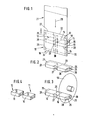
- the present exemplary embodiment relates to the wrapping of cuboid packs 10, 11, in particular cigarette packs, into a blank made of a plastic film or cellophane.
- the packs 10, 11 are delimited by the front 12 and back 13, by end faces 14 and 15 and by long sides 16 and 17.
- a special feature is that several, namely two spaced packs 10 and 11 are aligned in the transverse direction and fed at a distance from one another and together in one appropriately sized overall cut 18 are wrapped. This is divided into twice the width of an individual film blank 19 or 20 for a pack 10, 11 from a continuous material web 21 by a cross-cut 22.
- the overall blank 18 is then placed in a U-shape around the two packs 10, 11 (FIG. 2), in such a way that upper and lower tubular tabs 23, 24 protrude on the rear side in the transport direction (long sides 17). Laterally, that is to say transversely to the conveying direction, upper and lower longitudinal front flaps 25 and 26 project beyond the front sides 14, 15. In an extension of the forward longitudinal sides 16, side end flaps 27 and 28 are formed by the overall blank 18.
- the side end flaps 27 and 28 for each pack 10, 11 are first folded on the end face 14, 15 thereof.
- the overall blank 18 has a previously made pre-cut 29 in the area of the side end flaps 27 to be formed. This is located in the middle between the packs 10, 11 in the area of a material strip 30 in the double width of a side face flap 27.
- the pre-cut 29 is already made in the material web 21 at a predetermined position. Due to the length of the pre-cut 29, the folding of the side end flaps 27 against the mutually facing end faces 14, 15 of the packs 10, 11 is possible while maintaining the unity of the overall blank 18.
- a blanking tube is formed by folding and partially covering the tube tabs 23, 24 and by connecting them (FIG. 3).
- the entire blank 18 is then cut in the area between the packs 10, 11, namely in addition to the pre-cut 29.
- the tabs then still protruding on the end faces 14, 15, namely longitudinal end flaps 25 and 26 and rear side end flaps 30, become more common Folded against the end faces 14, 15 so that the folding image of the packs 10, 11 shown in FIG. 4 is generated.
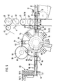
- the packs 10, 11 (in pairs) lying next to one another are delivered in succession on a common feed path 31.
- a circulating conveyor (chain conveyor 32) is used to transport the packs 10, 11 on the horizontal feed conveyor 31. From this, the packs 10, 11 are taken over by a slide 33 which dips from above into the path of movement of the packs 10, 11 and the packs 10, 11 by grasping on the back (long sides 17) until they are received in a pocket 34 Revolvers 35 transported on. After the packs 10, 11 have been transferred to the turret 35, the slide 33 is moved upward and returns to the starting position shown in dashed lines above the feed path 31. Entry into this takes place via an opening 36 in an upper guide 37 of the feed conveyor track 31.
- the overall blank 18 is fed transversely to the conveying direction of the packs 10, 11, in the present case in a vertical plane, from top to bottom.
- the entire blank 18 is transported in the region on both sides of the feed conveyor 31 by suction air acted on conveyor belts, namely two perforated belts 38 and 39 running at a distance from one another.
- the configuration of the same and the device for applying suction air to the perforated belts 38, 39 can be carried out in a suitable manner, in particular in the embodiment of DE-OS 25 30 992.
- the perforated belts 38, 39 are guided over an upper deflecting roller 40 and a lower, not shown corresponding deflecting roller below the feed conveyor 31.
- the material web 21 is fed to the above-described film conveyor, namely the perforated belts 38, 39 via pull rollers 41, 42.
- These also have the task of making the pre-cut 29 at a suitable location within the material web 21.
- the larger diameter roller 42 is equipped with knife segments 43 and 44 which protrude beyond the outer surface of the roller 42 and make the pre-cut of the appropriate length in the material web 21.
- two pre-cuts 29 are accordingly made, that is to say two overall cuts 18 are prepared accordingly.
- the knife segments 43, 44 are arranged centrally on the pull roller 42 when two packs 10, 11 are simultaneously wrapped.
- the opposite, smaller pull roller 41 is provided in the same plane, that is to say also centrally in the present case, with a circumferential groove 45, into which the knife segments 43, 44 enter when performing the cut 29.
- a further separating device is arranged upstream of the deflecting roller 40, namely a knife roller 46 with a fixed counter knife 47.
- a (transverse) partial cut is made in the material web 21 by this separating device, essentially Lichen in the area of the perforated strips 38, 39, which subsequently capture the material web 21.
- a main cut adjoining the partial cuts to complete the continuous cross-cutting cut 42 is produced in the region of the perforated strips 38, 39 lying between them by a further knife roller 48 with counter knife 49.
- the method of severing a material web 21 in several successive partial cuts is carried out according to the features of DE-OS 25 30 992.
- a U-shaped cut for producing two grip tongues 50 is made in the region of a tear strip 51 applied to the material web 21.
- the tear strips 51 are attached in such a way that they run eccentrically in the usual manner within the wrapping of the finished packs 10, 11, namely facing one of the end faces.
- the thus cut and prepared overall blanks 18 are gripped in the area of a mouthpiece 52 by two packs 10, 11, which are simultaneously conveyed at a distance from one another, conveyed through the mouthpiece 52 into a pocket 34 of the revolver 35 held ready immediately after the mouthpiece 52
- Overall blank 18 is placed around the packs 10, 11 in a U-shape in the manner described.
- the pocket 34 is dimensioned in the radial direction such that the packs 10, 11 are essentially flush with the outer boundary of the pocket 34 with the rear or outer longitudinal side 17.
- Hose tabs 23, 24 projecting rearward accordingly protrude from the pocket 34.
- a folding element 53 designed as an arcuate plate is moved in the circumferential direction of the revolver 35 and concentrically to it - in the illustration in FIG. 5 in the upward direction.
- the lower tube tab 24 is thereby folded over against the long side 17 and fixed in this position until the revolver is transported in the counterclockwise direction.
- the circular-arc-shaped folding member 53 is accordingly moved back and forth in the circumferential direction to carry out the folds.
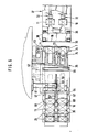
- the pocket 34 with the inserted packs 10, 11 arrives in the area of a fixed guide wall 54 closely clinging to the circumference of the turret 35.
- the guide wall 54 merges into the upper part of the mouthpiece 52.
- the partially overlapping tubular tabs 23, 24 are connected to one another in the area of a sealing station by a sealing tool in the form of a sealing strip 55 by means of pressure and thermal action.
- the sealing strip is brought from the outside to the longitudinal side 17 or to the tubular tabs 23, 24, the sealing strip 55 passing through a slot-shaped opening 56 in the guide wall 54.
- the sealing strip 55 is in the present the embodiment can be moved into the sealing position by a swivel arm 57.
- a separation station 58 follows. In this, the blanking tube is severed in the middle or in the middle between two adjacent packs 10, 11.
- a disc-shaped, rotationally driven thin cutting knife 59 enters the revolver 35, through a knife slot 60 in the guide wall 54.
- a drive shaft 61 for the cutting knife 59 is arranged outside the turret or outside the guide wall 54, parallel to the axis of a turret shaft 62.
- the revolver 35 itself in the area of the pockets 34 is provided with a thin knife gap 63 running all around. This enables the cutting knife 59 to penetrate into the turret 35 with the required depth in such a way that the cutting tube can be completely severed in the cutting station 58.
- a subsequent ejection station 64 there are packs 10, 11 with separate, individual film blanks 19 and 20 in the pocket 34.
- the packs 10, 11 with the film blanks are moved by a pusher 65 which can be moved in a suitable manner in the radial direction 19, 20 ejected together.
- a discharge track 66 connects to the turret 34.
- Side guides of the same are equipped in a known manner as folding members.
- the inlet end of the discharge conveyor 66 adjoining the turret 35 is laterally provided with a folding tongue 67. This folds the one when it is extended of the packs 10, 11 from the turret 35, the side end flaps 30 now lying forward against the assigned end faces 14 and 15.
- the lower longitudinal end flap 26 is folded against the end face 14, 15, by a fixed folding switch 68.
- the upstream packing tower 69 adjoins the horizontal discharge conveyor 66 in the present case, into which the mostly finished packs 10, 11 are inserted one after the other from below by a plunger 70.
- the upper longitudinal front flap 25 is folded through the side walls of the same to complete the packing 10, 11 against the end face 14, 15. The completed packs 10, 11 are thus transported further within the packing tower 69.
- a special feature is that when the packs 10, 11 are inserted, the side end flaps 27 and 28, which are initially in the transport direction, are folded against the associated end faces 14, 15 by stationary organs, although the unit of the overall blank 18 still exists of the revolver 35 are equipped with index fingers 71 and 72 for this purpose.
- These folding members form the side boundary of the pockets 34, the folding fingers 72, which extend in the center in the radial direction, being separated from one another by the knife gap 63.
- the pockets 34 which extend over the full width of the revolver 35 designed in the present case on two packs 10, 11, are accordingly divided into two partial pockets by the middle folding fingers 72, each for receiving a pack 10, 11.
- the pockets 34 of the turret 35 are, moreover, each formed by tongues 73 and 74 arranged in pairs at a distance from one another for reasons of material saving.
- the device described is not only suitable for processing two packs at the same time. As can be seen, with the appropriate design of the pockets of a revolver and the conveying and separating elements, several packs can be processed in a line next to one another, whereby a common overall cut for all packs or several overall cuts each covering two packs can be used .
Landscapes
- Engineering & Computer Science (AREA)
- Mechanical Engineering (AREA)
- Wrapping Of Specific Fragile Articles (AREA)
- Basic Packing Technique (AREA)
Abstract
Zur Erhöhung der Leistungsfähigkeit von Verpackungsmaschinen, insbesondere für die Herstellung von Zigaretten-Packungen (10, 11), soll die Leistungsfähigkeit einer Vorrichtung zum Einhüllen der Packungen in einen Außenzuschnitt (Folien-Zuschnitt 19, 20) erhöht werden. Zu diesem Zweck werden gleichzeitig mehrere, insbesondere zwei nebeneinanderliegende Packungen (10, 11) zugeführt und in einen gemeinsamen Gesamt-Zuschnitt (18) entsprechender Breite eingehüllt. Nach Bildung eines stabilen Zuschnittschlauchs, der beide Packungen (10, 11) umhüllt, erfolgt die Durchtrennung des Gesamt-Zuschnitts (18) unter Bildung der einzelnen Folien-Zuschnitte (19, 20), die im weiteren fertiggefaltet werden.In order to increase the performance of packaging machines, in particular for the production of cigarette packs (10, 11), the performance of a device for wrapping the packs in an outer cut (film cut 19, 20) is to be increased. For this purpose, several, in particular two adjacent packs (10, 11) are fed in simultaneously and wrapped in a common overall blank (18) of corresponding width. After the formation of a stable blank tube which envelops both packs (10, 11), the entire blank (18) is cut through to form the individual foil blanks (19, 20), which are subsequently folded.
Description
Die Erfindung betrifft ein Verfahren zum Einhüllen von Gegenständen in Zuschnitte, insbesondere von Pakkungen (Zigaretten-Packungen) in Folien-Zuschnitte, die U-förmig um die relativ zu diesen geförderten Packungen herumgefaltet und danach fertiggefaltet werden. Weiterhin betrifft die Erfindung eine Vorrichtung zur Durchführung des vorstehenden Verfahrens.The invention relates to a method for wrapping objects in blanks, in particular packs (cigarette packs) in foil blanks, which are folded in a U-shape around the packs conveyed relative to them and then finished. Furthermore, the invention relates to a device for performing the above method.
Zigaretten-Packungen sind überwiegend mit einer Außenumhüllung versehen, die aus einer Zellglas-Folie oder - neuerdings - aus einer Kunststoff-Folie besteht. Der Folien-Zuschnitt wird beim Einhüllen der Packung vorwiegend von einer Längsseite der (quaderförmigen) Packung ausgehend U-förmig um diese herumgelegt, so daß im Bereich von Stirnseiten sowie einer gegenüberliegenden Längsseite Zuschnitteile über die Packung hinweg stehen. Diese werden durch bewegbare oder ortsfeste Faltorgane infolge Relativbewegung mit der Packung gegen die zugeordneten Seiten derselben gefaltet. Im Bereich der einen Längsseite einander überdeckende Schlauchlappen des Folien-Zuschnitts können dabei miteinander verbunden sein, durch Schweißung oder Klebung.Cigarette packs are predominantly provided with an outer wrapper, which consists of a cellophane film or - more recently - a plastic film. When wrapping the pack, the film blank is predominantly placed in a U-shape around the long side of the (cuboid) pack, so that cut parts stand over the pack in the region of the end faces and an opposite long side. These are folded by means of movable or stationary folding members as a result of relative movement with the pack against the associated sides thereof. In the region of the tubular flaps of the film blank which overlap one another on the long side, they can be connected to one another by welding or gluing.
Bei der Verpackung von Zigaretten werden extrem hohe Taktzeiten erzielt. An die Verpackungsmaschinen angeschlossene Folien-Einschlagmaschinen sind häufig nicht mehr in der Lage, den hohen Ausstoß fertiger Zigaretten-Packungen ordnungsgemäß mit einem Folien-Einschlag zu versehen.Extremely high cycle times are achieved when packaging cigarettes. Foil wrapping machines connected to the packaging machines are often no longer able to properly pack the high output of finished cigarette packs with a foil wrapper.
Aufgabe der Erfindung ist demgemäß, die Leistungsfähigkeit im Bereich des Folieneinschlags zu erhöhen, ohne daß sich infolge übermäßiger Fördergeschwindigkeiten der empfindlichen (Zigaretten-)Packungen Nachteile durch mechanische Beanspruchung derselben ergeben.The object of the invention is accordingly to increase the performance in the area of film wrapping, without there being disadvantages as a result of mechanical stressing of the sensitive (cigarette) packs as a result of excessive conveying speeds.
Zur Lösung der vorstehenden Aufgabe wird erfindungsgemäß vorgeschlagen, daß wenigstens zwei Packungen mit Querabstand voneinander gleichzeitig zugefördert, ein gemeinsamer, entsprechend dimensionierter Gesamt- Zuschnitt um beide Packungen herumgefaltet und danach im Bereich zwischen den Packungen durchtrennt wird.To achieve the above object, it is proposed according to the invention that at least two packs with transverse spacing from each other are fed simultaneously, a common, appropriately dimensioned overall blank is folded around both packs and then severed in the area between the packs.
Nach dem erfindungsgemäßen Verfahren wird demnach in mehrbahnigem Betrieb gearbeitet, insbesondere mit zwei gleichzeitig und in gleichen Querebenen geförderten (Zigaretten-)Packungen. Die weitere Besonderheit liegt nun darin, daß den nebeneinanderliegenden Packungen ein gemeinsamer, entsprechend bemessener Gesamt-Zuschnitt zugeführt und um die Packungen U-förmig herumgefaltet wird. Durch die Verwendung eines Gesamt-Zuschnitts für alle gleichzeitig zugeführten Packungen hat den Vorteil, daß die Faltvorgänge präziser und schneller ablaufen können. Die durch den gemeinsamen Gesamt-Zuschnitt zusammengehaltenen Packungen bilden eine gut zu handhabende Einheit. Auch ist ein Zuschnitt in der Größe eines Gesamt-Zuschnitts bei dem üblichen äußerst dünnwandigen Material leichter zu handhaben.The method according to the invention is therefore used in multi-lane operation, in particular with two (cigarette) packs conveyed simultaneously and in the same transverse planes. Another special feature is that a common, appropriately sized overall blank is fed to the adjacent packs and folded around the packs in a U-shape. The use of an overall blank for all packs fed in at the same time has the advantage that the folding processes can be carried out more precisely and more quickly. The packs held together by the common overall cut form a unit that is easy to handle. A blank the size of a total blank is easier to handle with the usual extremely thin-walled material.
Nach einem weiteren Vorschlag der Erfindung wird nach dem U-förmigen Umlegen des Gesamt-Zuschnitts ein Zuschnitt-Schlauch entsprechender Länge gebildet durch Überlappen von randseitigen Schlauchlappen und Verbinden derselben miteinander. Es liegt nun ein dreidimensional geformter Gesamtzuschnitt vor, der im Bereich zwischen den auf Abstand gehaltenen Packungen durchtrennt werden kann, ohne daß sich Relativverschiebungen der Packungen bzw. der nunmehr gewonnenen Folien-Zuschnitte zueinander einstellen.According to a further proposal of the invention, after the entire blank has been folded over in a U-shape, a blank tube of the appropriate length is formed by overlapping edge-side tube tabs and connecting them to one another. There is now a three-dimensionally shaped overall blank which can be severed in the area between the packs which are kept at a distance, without any relative displacements of the packs or the sheet blanks now obtained from one another.
Vor der Bildung des Zuschnitt-Schlauchs werden erfindungsgemäß in Transportrichtung vornliegende, an den Längsseiten überstehende Seitenstirnlappen des Gesamt-Zuschnitts umgefaltet, nämlich gegen die zugeordnete Stirnseite der Packung, und zwar durch ortsfeste Faltorgane. Dies gilt auch für die im Bereich zwischen den nebeneinander geförderten Packungen gebildeten Seitenstirnlappen. Zu diesem Zweck ist erfindungsgemäß der Gesamt-Zuschnitt bzw. eine Material- Bahn zur Bildung der Zuschnitte an passender Stelle mit einem Vorschnitt versehen, der sich in Längsrichtung der Material-Bahn bzw. in Transportrichtung des Gesamtzuschnitts etwa in der Mitte desselben erstreckt und die dort zu faltenden Seitenstirnlappen voneinander trennt.Before the blanking tube is formed, according to the invention, front end flaps of the entire blank that are protruding in the direction of transport and protrude on the long sides are folded over, namely against the assigned end face of the pack, by means of stationary folding members. This also applies to the side end lobes formed in the area between the packs conveyed next to one another. For this purpose, according to the invention, the overall cut or a material Provide the web with a pre-cut to form the blanks at a suitable point, which extends approximately in the longitudinal direction of the material web or in the transport direction of the overall blank and separates the side end flaps to be folded there.
Dadurch ist es möglich, die gleichzeitig geförderten, nebeneinanderliegenden Packungen zusammen mit dem Gesamtzuschnitt in einen umlaufenden Förderer, insbesondere in die Taschen eines Revolvers einzuschieben, wobei während der Einschubbewegung durch an dem Revolver angeordnete Faltdaumen die in Förderrichtung vornliegenden Seitenstirnlappen in der beschriebenen Weise umgefaltet werden.This makes it possible to insert the packs, which are conveyed at the same time, next to one another, together with the overall blank, into a rotating conveyor, in particular into the pockets of a revolver.
Die erfindungsgemäße Vorrichtung zum Einhüllen von Zigaretten-Packungen in Folien-Zuschnitte ist demnach mit einem umlaufenden Förderer, insbesondere einem Revolver ausgerüstet, der in Radialrichtung nach außen offene Taschen aufweist, die quer zur Förderrichtung der Anzahl der Packungen entsprechend dimensioniert sind. Außen an den Taschen sowie mittig bzw. in einem dem Abstand der Packungen voneinander entsprechenden Abstand sind an den Taschen des Revolvers feststehende Faltdaumen angeordnet.The device according to the invention for wrapping cigarette packs in film blanks is accordingly equipped with a revolving conveyor, in particular a revolver, which has pockets which are open in the radial direction and which are dimensioned correspondingly to the number of packs transversely to the conveying direction. Fixed folding thumbs are arranged on the pockets of the revolver on the outside of the pockets and in the center or at a distance corresponding to the distance between the packs.
Des weiteren ist erfindungsgemäß dem Revolver ein Trennmesser zugeordnet, insbesondere eine rotierend angetriebene Messerscheibe, die in einen umlaufenden, schmalen Messerschlitz des Revolvers ragt und im Bereich einer Trennstation den (schlauchförmigen) Gesamt- Zuschnitt durchtrennt.Furthermore, according to the invention, a revolving knife is assigned to the revolver, in particular a rotatingly driven knife disk which projects into a circumferential, narrow knife slot of the revolver and cuts through the (tubular) overall blank in the area of a separating station.
Weitere Einzelheiten der Erfindung beziehen sich auf die Ausbildung des (Gesamt-)Zuschnitts, der Vorrichtung zur Vorbereitung desselben bzw. zur Vorbehandlung der Materialbahn, auf die Ausbildung des Revolvers sowie die nachgeordneten Förder- und Faltorgane.Further details of the invention relate to the formation of the (overall) blank, the Vorrich for the preparation of the same or for the pre-treatment of the material web, for the formation of the revolver and the downstream conveying and folding elements.
Verfahren und Vorrichtung werden nachfolgend anhand der Zeichnungen näher erläutert. Es zeigen:
- Fig. 1 einen Abschnitt einer vertikal geförderten Material-Bahn mit zwei einzuhüllenden Packungen in perspektivischer Darstellung,
- Fig. 2 zwei Packungen nach teilweisem Einhüllen durch einen Gesamt-Zuschnitt, ebenfalls in perspektivischer Darstellung,
- Fig. 3 eine Phase während der Herstellung der Einzelzuschnitte für jede Packung durch Trennmesser,
- Fig. 4 zwei nebeneinander geförderte, durch je einen Folien-Zuschnitt eingehüllte Packungen,
- Fig. 5 eine Vorrichtung zum Herstellen von Packungen gemäß Fig. 1 bis 4 in schematischer Seitenansicht,
- Fig. 6 die Vorrichtung gemäß Fig. 5 im Grundriß,
- Fig. 7 eine Vorderansicht der Vorrichtung im Bereich eines Vertikalförderers.
- 1 shows a section of a vertically conveyed material web with two packs to be wrapped in a perspective view,
- 2 two packs after partial wrapping by a total blank, also in perspective,
- 3 shows a phase during the production of the individual blanks for each pack by means of a cutting knife,
- 4 two packs conveyed side by side, each wrapped by a film blank,
- 5 shows a device for producing packs according to FIGS. 1 to 4 in a schematic side view,
- 6 shows the device according to FIG. 5 in plan view,
- Fig. 7 is a front view of the device in the region of a vertical conveyor.
Das vorliegende Ausführungsbeispiel bezieht sich auf das Einhüllen von quaderförmigen Packungen 10, 11, insbesondere Zigaretten-Packungen, in einen Zuschnitt aus einer Kunststoff-Folie oder aus Zellglas. Die Packungen 10, 11 sind durch Vorderseite 12 und Rückseite 13, durch Stirnseiten 14 und 15 sowie durch Längsseiten 16 und 17 begrenzt.The present exemplary embodiment relates to the wrapping of
Eine Besonderheit besteht darin, daß mehrere, nämlich zwei mit Abstand voneinander angeordnete Packungen 10 und 11 in Querrichtung ausgerichtet und mit Abstand voneinander zugefördert und gemeinsam in einen entsprechend bemessenen Gesamtzuschnitt 18 eingehüllt werden. Dieser wird in der doppelten Breite eines einzelnen Folienzuschnitts 19 bzw. 20 für je eine Packung 10, 11 von einer fortlaufenden Materialbahn 21 durch einen Quertrennschnitt 22 abgeteilt. Der Gesamtzuschnitt 18 wird sodann U-förmig um die beiden Packungen 10, 11 herumgelegt (Fig. 2), derart, daß auf der in Transportrichtung rückwärtigen Seite (Längsseiten 17) obere und untere Schlauchlappen 23, 24 überstehen. Seitlich, also quer zur Förderrichtung, ragen obere und untere Längsstirnlappen 25 und 26 über die Stirnseiten 14, 15 hinweg. In Verlängerung der nach vorn gerichteten Längsseiten 16 sind Seitenstirnlappen 27 und 28 durch den Gesamt-Zuschnitt 18 gebildet.A special feature is that several, namely two
Durch Transport der Packungen 10, 11 mit dem Gesamt- Zuschnitt 18 relativ zu entsprechenden Faltorganen werden zunächst die Seitenstirnlappen 27 und 28 für jede Packung 10, 11 an deren Stirnseite 14, 15 gefaltet. Die einander zugekehrten, also mittigen Seitenstirnlappen 27 werden ebenfalls umgefaltet. Dies wird dadurch ermöglicht, daß der Gesamtzuschnitt 18 im Bereich der zubildenden Seitenstirnlappen 27 einen zuvor angebrachten Vorschnitt 29 aufweist. Dieser befindet sich mittig zwischen den Packungen 10, 11 im Bereich eines Materialstreifens 30 in der doppelten Breite eines Seitenstirnlappens 27. Bei dem vorliegenden Ausführungsbeispiel wird der Vorschnitt 29 bereits in der Materialbahn 21 an vorbestimmter Stelle angebracht. Aufgrund der Länge des Vorschnittes 29 ist das Einfalten der Seitenstirnlappen 27 gegen die einander zugekehrten Stirnseiten 14, 15 der Packungen 10, 11 bei Aufrechterhaltung der Einheit des Gesamt- Zuschnitts 18 im übrigen möglich.By transporting the
Sodann wird durch Umfalten und teilweises Überdecken der Schlauchlappen 23, 24 sowie durch Verbinden derselben ein Zuschnittschlauch gebildet (Fig. 3). Danach erfolgt die Durchtrennung des Gesamt-Zuschnitts 18 im Bereich zwischen den Packungen 10, 11, nämlich in Ergänzung des Vorschnitts 29. Die an den Stirnseiten 14, 15 dann noch überstehenden Lappen, nämlich Längsstirnlappen 25 und 26 sowie rückseitige Seitenstirnlappen 30, werden in üblicher Weise gegen die Stirnseiten 14, 15 gefaltet, so daß das aus Fig. 4 ersichtliche Faltbild der Packungen 10, 11 erzeugt ist.Then a blanking tube is formed by folding and partially covering the
Bei dem gezeigten Ausführungsbeispiel der Vorrichtung werden die Packungen 10, 11 (paarweise) nebeneinander liegend auf einer gemeinsamen Zuförderbahn 31 aufeinanderfolgend angeliefert. Zum Transport der Packungen 10, 11 auf der horizontalen Zuförderbahn 31 dient zunächst ein Umlaufförderer (Kettenförderer 32). Von diesem werden die Packungen 10, 11 durch einen Schieber 33 übernommen, der von oben her in die Bewegungsbahn der Packungen 10, 11 eintaucht und die Packungen 10, 11 durch Erfassen an der Rückseite (Längsseiten 17) bis zur Aufnahme in einer Tasche 34 eines Revolvers 35 weitertransportiert. Nach Übergabe der Packungen 10, 11 an den Revolver 35 wird der Schieber 33 aufwärtsbewegt und kehrt in die gestrichelt gezeigte Ausgangsposition oberhalb der Zuförderbahn 31 zurück. Der Eintritt in diese erfolgt über eine Öffnung 36 in einer Oberführung 37 der Zuförderbahn 31.In the exemplary embodiment of the device shown, the
Quer zur Förderrichtung der Packungen 10, 11 wird der Gesamt-Zuschnitt 18 zugeführt, im vorliegenden Falle in vertikaler Ebene, von oben nach unten. Der Transport des Gesamt-Zuschnitts 18 im Bereich zu beiden Seiten der Zuförderbahn 31 erfolgt durch mit Saugluft beaufschlagte Förderbänder, nämlich zwei im Abstand voneinander laufende Lochbänder 38 und 39. Die Ausgestaltung derselben sowie die Einrichtung zur Beaufschlagung der Lochbänder 38, 39 mit Saugluft kann in geeigneter Weise erfolgen, insbesondere in der Ausführung der DE-OS 25 30 992 . Die Lochbänder 38, 39 sind über eine obere Umlenkwalze 40 und eine untere, nicht dargestellte entsprechende Umlenkwalze unterhalb der Zuförderbahn 31 geführt.The overall blank 18 is fed transversely to the conveying direction of the
Die Materialbahn 21 wird dem vorstehend erläuterten Folienförderer, nämlich den Lochbändern 38, 39 über Zugwalzen 41, 42 zugeführt. Diese haben zugleich die Aufgabe, den Vorschnitt 29 an geeigneter Stelle innerhalb der Materialbahn 21 anzubringen. Zu diesem Zweck ist die im Durchmesser größere Zugwalze 42 mit Messersegmenten 43 und 44 ausgestattet, die über die Mantelfläche der Zugwalze 42 hinwegragen und den Vorschnitt entsprechender Länge in der Materialbahn 21 anbringen. Bei einer Umdrehung der Zugwalze 42 werden demnach zwei Vorschnitte 29 angebracht, also zwei Gesamtzuschnitte 18 entsprechend vorbereitet. Die Messersegmente 43, 44 sind bei der gleichzeitigen Einhüllung von zwei Packungen 10, 11 mittig auf der Zugwalze 42 angeordnet. Die gegenüberliegende, kleinere Zugwalze 41 ist in gleicher Ebene, also im vorliegenden Falle ebenfalls mittig, mit einem ringsherumlaufenden Einstich 45 versehen, in den die Messersegmente 43, 44 bei der Durchführung des Vorschnitts 29 eintreten.The
Der Umlenkwalze 40 ist oberhalb derselben eine weitere Trennvorrichtung vorgeordnet, nämlich eine Messerwalze 46 mit einem feststehenden Gegenmesser 47. Durch diese Trenneinrichtung wird ein (quergerichteter) Teilschnitt in der Materialbahn 21 angebracht, und zwar im wesentlichen im Bereich der die Materialbahn 21 danach erfassenden Lochbänder 38, 39. Ein an die Teilschnitte anschließender Hauptschnitt zur Vollendung des durchgehenden Quertrennschnitts 42 wird im Bereich der Lochbänder 38, 39 zwischen diesen liegend durch eine weitere Messerwalze 48 mit Gegenmesser 49 hergestellt. Das Verfahren der Durchtrennung einer Materialbahn 21 in mehreren aufeinanderfolgenden Teilschnitten wird nach den Merkmalen der DE-OS 25 30 992 durchgeführt. Mit dem Quertrennschnitt 22 wird ein U-förmiger Trennschnitt zur Erzeugung von zwei Griffzungen 50 jeweils im Bereich eines auf die Materialbahn 21 aufgebrachten Aufreißstreifens 51 angebracht. Die Aufreißstreifen 51 sind so angebracht, daß sie in der üblichen Weise innerhalb der Umhüllung der fertigen Packungen 10, 11 außermittig, nämlich einer der Stirnseiten zugekehrt, verlaufen.A further separating device is arranged upstream of the deflecting
Die so abgetrennten und vorbereiteten Gesamt-Zuschnitte 18 werden im Bereich eines Mundstücks 52 von zwei im Abstand voneinander gleichzeitig geförderten Pakkungen 10, 11 erfaßt, durch das Mundstück 52 hindurchgefördert in eine unmittelbar im Anschluß an das Mundstück 52 bereitgehaltene Tasche 34 des Revolvers 35. Der Gesamt-Zuschnitt 18 legt sich dabei U-förmig in der beschriebenen Weise um die Packungen 10, 11 herum. Die Tasche 34 ist in Radialrichtung so bemessen, daß die Packungen 10, 11 mit der rückseitigen bzw. äußeren Längsseite 17 im wesentlichen bündig mit der äußeren Begrenzung der Tasche 34 abschließen. Nach rückwärts überstehende Schlauchlappen 23, 24 ragen demnach aus der Tasche 34 heraus.The thus cut and prepared
Als nächstes werden nun die vorgenannten Schlauchlappen 23 und 24 gegen die zugeordnete Längsseite 17 gefaltet, und zwar zunächst der untere Schlauchlappen 24. Zu diesem zweck wird ein als bogenförmige Platte ausgebildetes Faltorgan 53 in Umfangsrichtung des Revolvers 35 und konzentrisch zu diesem bewegt - bei der Darstellung in Fig. 5 in Aufwärtsrichtung. Der untere Schlauchlappen 24 wird dadurch gegen die Längsseite 17 umgefaltet und bis zum Weitertransport des Revolvers im Gegenuhrzeigersinn in dieser Stellung fixiert. Das kreisbogenförmige Faltorgan 53 wird demnach hin-und hergehend in Umfangsrichtung zur Durchführung der Faltungen bewegt.Next, the
Durch die Weiterschaltung des Revolvers 35 gelangt die Tasche 34 mit den eingeführten Packungen 10, 11 in den Bereich einer feststehenden, eng an den Umfang des Revolvers 35 angeschmiegten Führungswand 54. Die Führungswand 54 geht in den oberen Teil des Mundstücks 52 über.By advancing the
Sobald durch Weiterdrehung des Revolvers 35 die Tasche 34 in den Bereich der Führungswand 54 gelangt, wird der obere Schlauchlappen 23 gegen die Längsseite 17 der Packungen 10, 11 umgefaltet bzw. gegen den bereits vorher gefalteten Schlauchlappen 24. Damit ist der Zuschnittschlauch hergestellt.As soon as the
Die einander teilweise überdeckenden Schlauchlappen 23, 24 werden im Bereich einer Siegelstation durch ein Siegelwerkzeug in Gestalt einer Siegelleiste 55 durch Druck und thermische Beaufschlagung miteinander verbunden. Die Siegelleiste wird von außen her an die Längsseite 17 bzw. an die Schlauchlappen 23, 24 herangeführt, wobei die Siegelleiste 55 durch eine schlitzförmige Öffnung 56 in der Führungswand 54 hindurchtritt. Die Siegelleiste 55 ist bei dem vorliegenden Ausführungsbeispiel durch einen Schwenkarm 57 in die Siegelposition bewegbar.The partially overlapping
Im Anschluß an die Fertigstellung und Stabilisierung des Zuschnittschlauchs folgt eine Trennstation 58. In dieser wird der Zuschnittschlauch mittig bzw. in der Mitte zwischen zwei benachbarten Packungen 10, 11 durchtrennt. Zu diesem Zweck tritt ein im vorliegenden Falle scheibenförmig ausgebildetes, rotierend angetriebenes dünnes Trennmesser 59 in den Revolver 35 ein, durch einen Messerschlitz 60 in der Führungswand 54 hindurch. Eine Antriebswelle 61 für das Trennmesser 59 ist außerhalb des Revolvers bzw. außerhalb der Führungswand 54, achsparallel zu einer Revolverwelle 62 angeordnet.Following the completion and stabilization of the blanking tube, a
Der Revolver 35 selbst in im Bereich der Taschen 34 mit einem ringsherumlaufenden, dünnen Messerspalt 63 versehen. Dieser ermöglicht das Eindringen des Trennmessers 59 mit der erforderlichen Tiefe in den Revolver 35, derart, daß in der Trennstation 58 der Zuschnittschlauch vollständig durchtrennt werden kann.The
Im Bereich einer nachfolgenden Ausschubstation 64 befinden sich demnach Packungen 10, 11 mit voneinander getrennten, einzelnen Folien-Zuschnitten 19 und 20 in der Tasche 34. Durch einen in geeigneter Weise in Radialrichtung bewegbaren Ausstoßer 65 werden die Packungen 10, 11 mit den Folien-Zuschnitten 19, 20 gemeinsam ausgestoßen. An den Revolver 34 schließt eine Abförderbahn 66 an. Seitenführungen derselben sind in bekannter Weise als Faltorgane ausgerüstet. Das an den Revolver 35 anschließende Eintrittsende der Abförderbahn 66 ist seitlich mit einer Faltzunge 67 versehen. Diese faltet jeweils die beim Ausschub der Packungen 10, 11 aus dem Revolver 35 nunmehr vornliegenden Seitenstirnlappen 30 gegen die zugeordneten Stirnseiten 14 und 15. Im weiteren Verlauf, nämlich durch den Transport innerhalb der Abförderbahn 66, wird im vorliegenden Fall der untere Längsstirnlappen 26 gegen die Stirnseite 14, 15 gefaltet, und zwar durch eine feststehende Faltweiche 68.In the area of a
An die im vorliegenden Falle horizontale Abförderbahn 66 schließt ein aufwärtsgerichteter Packungsturm 69 an, in den die überwiegend fertiggestellten Packungen 10, 11 nacheinander von unten her durch einen Stößel 70 eingeschoben werden. Durch den Eintritt in den Packungsturm 69 wird durch Seitenwandungen desselben der obere Längsstirnlappen 25 unter Vollendung der Packung 10, 11 gegen die Stirnseite 14, 15 umgefaltet. Innerhalb des Packungsturms 69 werden somit die komplettierten Packungen 10, 11 weitertransportiert.The
Eine Besonderheit besteht darin, daß bei dem Einschub der Packungen 10, 11 die zunächst in Transportrichvornliegenden Seitenstirnlappen 27 und 28 durch ortsfeste organe gegen die zugeordneten Stirnseiten 14, 15 gefaltet we n, obwohl die Einheit des Gesamt- Zuschnitts 18 noch besteh.D_ie Taschen 34 des Revolvers 35 sind zu diesem Zweck mit Schaltfingern 71 und 72 ausgerüstet. Diese Faltorgane bilden dTe Seitenbegrenzung der Taschen 34, wobei die in der Mitte derselben sich in Radialrichtung erstreckenden Faltfinger 72 durch den Messerspalt 63 voneinander getrennt sind. Die sich über die volle Breite des im vorliegenden Fall auf zwei Packungen 10, 11 ausgelegten Revolvers 35 sich erstreckenden Taschen 34 sind demnach durch die mittleren Faltfinger 72 in zwei Teiltaschen, je zur Aufnahme einer Packung 10, 11, unterteilt. Beim Einschub der Packungen 10, 11 in die so ausgebildete Tasche 34 werden demnach an beiden Seiten die in Einschubrichtung vornliegenden Seitenstirnlappen 27, 28 durch die Faltfinger 71 und 72 umgefaltet. Im Bereich zwischen den Packungen 10, 11 ist dieser Faltvorgang durch den Vorschnitt 29 möglich, ohne daß es zu Zwängungen oder Faltenbildung in dem Gesamt- zuschnitt 18 kommt.A special feature is that when the
Die Taschen 34 des Revolvers 35 sind im übrigen aus Gründen der Materialeinsparung jeweils durch paarweise im Abstand voneinander angeordnete Zungen 73 und 74 gebildet.The
Die beschriebene Vorrichtung ist nicht nur für die Verarbeitung von gleichzeitig zwei Packungen geeignet. Wie ersichtlich, können bei entsprechender Ausbildung von Taschen eines Revolvers sowie den Förder- und Trennorganen mehrere Packungen in einer Linie nebeneinander verarbeitet werden, wobei jeweils ein gemeinsamer Gesamt-Zuschnitt für alle Packungen oder mehrere, jeweils zwei Packungen erfassende Gesamt-Zuschnitte zum Einsatz kommen können.The device described is not only suitable for processing two packs at the same time. As can be seen, with the appropriate design of the pockets of a revolver and the conveying and separating elements, several packs can be processed in a line next to one another, whereby a common overall cut for all packs or several overall cuts each covering two packs can be used .
Claims (15)
Applications Claiming Priority (2)
| Application Number | Priority Date | Filing Date | Title |
|---|---|---|---|
| DE19833332950 DE3332950A1 (en) | 1983-09-13 | 1983-09-13 | METHOD AND DEVICE FOR ENHANCING CIGARETTE PACKS IN FILM CUTS |
| DE3332950 | 1983-09-13 |
Publications (3)
| Publication Number | Publication Date |
|---|---|
| EP0135818A2 true EP0135818A2 (en) | 1985-04-03 |
| EP0135818A3 EP0135818A3 (en) | 1986-06-04 |
| EP0135818B1 EP0135818B1 (en) | 1988-07-20 |
Family
ID=6208912
Family Applications (1)
| Application Number | Title | Priority Date | Filing Date |
|---|---|---|---|
| EP84110102A Expired EP0135818B1 (en) | 1983-09-13 | 1984-08-24 | Method and device for enveloping cigarette packages in sheets |
Country Status (6)
| Country | Link |
|---|---|
| US (1) | US4617780A (en) |
| EP (1) | EP0135818B1 (en) |
| JP (1) | JPH06528B2 (en) |
| BR (1) | BR8404551A (en) |
| CA (1) | CA1227414A (en) |
| DE (2) | DE3332950A1 (en) |
Cited By (8)
| Publication number | Priority date | Publication date | Assignee | Title |
|---|---|---|---|---|
| EP0197368A2 (en) * | 1985-04-06 | 1986-10-15 | Focke & Co. (GmbH & Co.) | Method and apparatus for packaging cigarettes in particular |
| EP0304736A2 (en) * | 1987-08-28 | 1989-03-01 | Focke & Co. (GmbH & Co.) | Method and device for enveloping, especially cigarette packages |
| DE4335666A1 (en) * | 1993-10-20 | 1995-04-27 | Focke & Co | Apparatus for the production of pack bundles |
| EP1260442A2 (en) * | 2001-05-11 | 2002-11-27 | G.D Societ Per Azioni | Method of overwrapping packets |
| WO2007014917A1 (en) * | 2005-07-29 | 2007-02-08 | Azionaria Costruzioni Macchine Automatiche A.C.M.A. S.P.A. | Method and machine for forming groups of products and an overwrapping about each group |
| WO2008089879A1 (en) * | 2007-01-22 | 2008-07-31 | Focke & Co. (Gmbh & Co. Kg) | Working device for packaging machines |
| EP1555228B2 (en) † | 2004-01-13 | 2011-11-16 | G.D Società Per Azioni | Method and device for transferring packets |
| US8631715B2 (en) | 2010-06-09 | 2014-01-21 | Copan Italia S.P.A. | Method for quantitative transfer of analytes |
Families Citing this family (34)
| Publication number | Priority date | Publication date | Assignee | Title |
|---|---|---|---|---|
| DE3618736A1 (en) * | 1986-06-04 | 1987-12-10 | Schmermund Maschf Alfred | METHOD AND DEVICE FOR ENHANCING CIGARETTE PACKAGES IN CLEAR VIEW FILM |
| DE3639994A1 (en) * | 1986-11-22 | 1988-05-26 | Focke & Co | PACKING MACHINE, IN PARTICULAR FOR CIGARETTE PACKS |
| DE3701273A1 (en) * | 1987-01-17 | 1988-07-28 | Focke & Co | METHOD AND DEVICE FOR PACKING PAPER HANDKERCHIEFS |
| DE3800432A1 (en) * | 1988-01-09 | 1989-07-20 | Hauni Werke Koerber & Co Kg | DEVICE FOR ENHANCING PACKS WITH HULL MATERIAL |
| DE3800664A1 (en) * | 1988-01-13 | 1989-07-27 | Focke & Co | METHOD AND DEVICE FOR PRODUCING A FOLDING BOXES HAVING A COLLAR, IN PARTICULAR FOR CIGARETTES |
| IT1236030B (en) * | 1989-10-11 | 1992-12-22 | Gd Spa | WRAPPING MACHINE OF SUBSTANTIALLY PARALLELEPIPED PRODUCTS |
| IT1252424B (en) * | 1991-07-16 | 1995-06-14 | Gd Spa | METHOD AND DEVICE FOR THE REALIZATION OF DIVIDED STICKS FOR CIGARETTE PACKAGES |
| IT1259800B (en) * | 1992-11-20 | 1996-03-26 | Gd Spa | METHOD AND DEVICE FOR THE CREATION OF TUBULAR SUPER-WRAPPING OF HEAT-SEALABLE MATERIAL. |
| GB9321148D0 (en) * | 1993-10-13 | 1993-12-01 | Molins Plc | Package blank feeding |
| ITBO940213A1 (en) * | 1994-05-16 | 1995-11-16 | Gd Spa | METHOD FOR MAKING CIGARETTE STICKS WITH RIGID CASING OF THE HINGED LID TYPE. |
| IT1285617B1 (en) * | 1996-03-15 | 1998-06-18 | Gd Spa | PRODUCT WRAPPING METHOD |
| IT1285922B1 (en) * | 1996-05-06 | 1998-06-26 | Gd Spa | METHOD AND DEVICE FOR THE FOLDING OF END FLAPS OF TUBULAR ENCLOSURES |
| IT1291264B1 (en) * | 1997-03-17 | 1998-12-30 | Gd Spa | BENDING METHOD FOR THE FORMATION OF A SEALED TUBE ENVELOPE |
| IT1304778B1 (en) * | 1998-07-06 | 2001-03-29 | Gd Spa | PACKAGING MACHINE. |
| DE19907579A1 (en) * | 1999-02-23 | 2000-09-14 | Topack Verpacktech Gmbh | Device for the transportation of objects |
| US6305146B1 (en) * | 1999-03-09 | 2001-10-23 | Jensen Ag Burgdorf | Process for the final folding and subsequent storage of a piece of linen and final folding means |
| DE10123804A1 (en) * | 2001-05-16 | 2002-11-28 | Christian Senning Verpackungsm | Method and device for simultaneous packaging on more than one packaging line |
| ITBO20030317A1 (en) * | 2003-05-22 | 2004-11-23 | Gd Spa | METHOD AND UNIT FOR WRAPPING OF GROUPS OF PRODUCTS. |
| ITBO20030706A1 (en) * | 2003-11-21 | 2005-05-22 | Gd Spa | PRODUCT WRAPPING UNIT. |
| ITBO20040434A1 (en) * | 2004-07-12 | 2004-10-12 | Gd Spa | METHOD FOR THE FORMATION OF A HINGED LID PORTFOLIO PACKAGE |
| ITBO20060237A1 (en) * | 2006-04-04 | 2006-07-04 | Gd Spa | METHOD AND MACHINE FOR THE PURCHASE OF ITEMS. |
| US8046978B2 (en) * | 2009-10-02 | 2011-11-01 | R.J. Reynolds Tobacco Company | Equipment and method for packaging multiple packets of cigarettes |
| DE102009060134A1 (en) | 2009-12-09 | 2011-06-16 | Focke & Co.(Gmbh & Co. Kg) | Packings, in particular for cigarettes, and method and apparatus for producing the same |
| HUE033794T2 (en) * | 2013-04-03 | 2018-01-29 | Jt Int Sa | Packaging apparatus and method |
| EP2894103B1 (en) | 2014-01-10 | 2016-09-07 | Robert Bosch Gmbh | Method and device for packaging food products into individual portions |
| DE102015001027A1 (en) * | 2014-11-27 | 2016-06-02 | Focke & Co. (Gmbh & Co. Kg) | Method and device for producing cigarette packets |
| ITUB20160604A1 (en) * | 2016-02-09 | 2017-08-09 | Ima Spa | UNITS AND METHOD FOR PLACING OBJECTS WITHIN BOXES. |
| ITUB20160589A1 (en) * | 2016-02-09 | 2017-08-09 | Ima Spa | UNITS AND METHOD FOR PLACING OBJECTS WITHIN BOXES. |
| DE102017002934A1 (en) * | 2017-03-24 | 2018-09-27 | Focke & Co. (Gmbh & Co. Kg) | Method and device for producing (cigarette) packages |
| IT201800010313A1 (en) | 2018-11-14 | 2020-05-14 | Gd Spa | Method and unit of feeding two sheets of wrapping into a packing machine |
| IT201800010315A1 (en) * | 2018-11-14 | 2020-05-14 | Gd Spa | Wrapping method to make two packages at the same time |
| US11618598B2 (en) | 2020-05-29 | 2023-04-04 | Ocme S.R.L. | Apparatus for making a multiplicity of packages |
| DE102022105779A1 (en) * | 2022-03-11 | 2023-09-14 | Focke & Co. (Gmbh & Co. Kg) | Device and method for handling blanks for wrapping packages for cigarette industry products |
| CN115140357A (en) * | 2022-04-29 | 2022-10-04 | 河南中烟工业有限责任公司 | Automatic plastic packaging machine for packaged cigarette packaged packing box |
Citations (3)
| Publication number | Priority date | Publication date | Assignee | Title |
|---|---|---|---|---|
| FR599407A (en) * | 1926-01-12 | |||
| AT293281B (en) * | 1967-01-10 | 1971-09-27 | Heinz Focke | Device for packing cigarettes in soft packs |
| GB2003817A (en) * | 1977-09-07 | 1979-03-21 | Focke & Co | Apparatus for applying wrappers to articles |
Family Cites Families (10)
| Publication number | Priority date | Publication date | Assignee | Title |
|---|---|---|---|---|
| DE802564C (en) * | 1949-07-13 | 1951-02-15 | Kurt Koerber & Co K G | Method and machine for packaging cigarettes and the like |
| DE1169835B (en) * | 1960-07-07 | 1964-05-06 | Hauni Werke Koerber & Co Kg | Wrapping machine for wrapping cigarette packs |
| DE1217848B (en) * | 1963-05-09 | 1966-05-26 | Hauni Werke Koerber & Co Kg | Method and device for wrapping cigarette packs and similar packaged goods in a plastic film |
| CH527090A (en) * | 1970-06-03 | 1972-08-31 | Sig Schweiz Industrieges | Process for packaging objects of the same type and machine for carrying out the process |
| DE2407580A1 (en) * | 1974-02-16 | 1975-08-21 | Focke Pfuhl Verpack Automat | PLANT FOR MANUFACTURING AND PACKAGING CIGARETTES OR DGL AND PROCEDURES FOR STORING THE SAME |
| IT1060149B (en) * | 1976-03-31 | 1982-07-10 | Gd Spa | PERFECTED DEVICE FOR THE REALIZATION OF THE INTERNAL WRAP OF TIN PAPER WITH OVERLAPPING OF THE LONGITUDINAL ENDS OF THE SPEZZON ON ONE OF THE MAJOR FACES OF THE CIGARETTE GROUP IN THE CIGARETTE MACHINE CONDITIONING MACHINES IN STUFFLED MULTI-STUFFED MULTI-STUFFED MULTI-STUFFED MULTI-STUFFED MULTIWOOD |
| IT1120350B (en) * | 1979-05-04 | 1986-03-19 | Gd Spa | MACHINE PERFECTED FOR WRAPPING AND GROUPING OF PRODUCTS |
| DE2949685A1 (en) * | 1979-12-11 | 1981-06-19 | Focke & Co, 2810 Verden | DEVICE FOR PRODUCING PACKAGE CUTS BY SEPARATING FROM A CONTINUOUS TRAIN |
| US4495745A (en) * | 1979-12-26 | 1985-01-29 | Package Machinery Company | Sealing wheel for forming fin seal package |
| JPS6016487Y2 (en) * | 1981-05-09 | 1985-05-22 | 日本包装機械株式会社 | Two-row product simultaneous packaging device |
-
1983
- 1983-09-13 DE DE19833332950 patent/DE3332950A1/en not_active Withdrawn
-
1984
- 1984-08-24 EP EP84110102A patent/EP0135818B1/en not_active Expired
- 1984-08-24 DE DE8484110102T patent/DE3472780D1/en not_active Expired
- 1984-08-29 US US06/645,187 patent/US4617780A/en not_active Expired - Lifetime
- 1984-09-12 CA CA000462990A patent/CA1227414A/en not_active Expired
- 1984-09-12 BR BR8404551A patent/BR8404551A/en not_active IP Right Cessation
- 1984-09-13 JP JP59190719A patent/JPH06528B2/en not_active Expired - Lifetime
Patent Citations (3)
| Publication number | Priority date | Publication date | Assignee | Title |
|---|---|---|---|---|
| FR599407A (en) * | 1926-01-12 | |||
| AT293281B (en) * | 1967-01-10 | 1971-09-27 | Heinz Focke | Device for packing cigarettes in soft packs |
| GB2003817A (en) * | 1977-09-07 | 1979-03-21 | Focke & Co | Apparatus for applying wrappers to articles |
Cited By (16)
| Publication number | Priority date | Publication date | Assignee | Title |
|---|---|---|---|---|
| EP0197368A2 (en) * | 1985-04-06 | 1986-10-15 | Focke & Co. (GmbH & Co.) | Method and apparatus for packaging cigarettes in particular |
| DE3512611A1 (en) * | 1985-04-06 | 1986-10-16 | Focke & Co (GmbH & Co), 2810 Verden | METHOD AND DEVICE FOR PACKING IN PARTICULAR CIGARETTES |
| EP0197368A3 (en) * | 1985-04-06 | 1987-01-07 | Focke & Co. (Gmbh & Co.) | Method and apparatus for packaging cigarettes in particular |
| DE3728716C2 (en) * | 1987-08-28 | 1999-10-07 | Focke & Co | Method for wrapping cuboid objects, in particular cigarette packs, and device for carrying out the method |
| DE3728716A1 (en) * | 1987-08-28 | 1989-03-09 | Focke & Co | METHOD AND DEVICE FOR PACKING IN PARTICULAR CIGARETTE PACKS |
| JPS6470322A (en) * | 1987-08-28 | 1989-03-15 | Focke & Co | Method and device for packaging package, particularly, cigarette pack |
| EP0304736A3 (en) * | 1987-08-28 | 1990-03-14 | Focke & Co. (Gmbh & Co.) | Method and device for enveloping, especially cigarette packages |
| EP0304736A2 (en) * | 1987-08-28 | 1989-03-01 | Focke & Co. (GmbH & Co.) | Method and device for enveloping, especially cigarette packages |
| DE4335666A1 (en) * | 1993-10-20 | 1995-04-27 | Focke & Co | Apparatus for the production of pack bundles |
| EP1260442A2 (en) * | 2001-05-11 | 2002-11-27 | G.D Societ Per Azioni | Method of overwrapping packets |
| EP1260442A3 (en) * | 2001-05-11 | 2003-01-02 | G.D Societ Per Azioni | Method of overwrapping packets |
| US6643996B2 (en) | 2001-05-11 | 2003-11-11 | G.D. Societa' Per Azioni | Method of overwrapping packets |
| EP1555228B2 (en) † | 2004-01-13 | 2011-11-16 | G.D Società Per Azioni | Method and device for transferring packets |
| WO2007014917A1 (en) * | 2005-07-29 | 2007-02-08 | Azionaria Costruzioni Macchine Automatiche A.C.M.A. S.P.A. | Method and machine for forming groups of products and an overwrapping about each group |
| WO2008089879A1 (en) * | 2007-01-22 | 2008-07-31 | Focke & Co. (Gmbh & Co. Kg) | Working device for packaging machines |
| US8631715B2 (en) | 2010-06-09 | 2014-01-21 | Copan Italia S.P.A. | Method for quantitative transfer of analytes |
Also Published As
| Publication number | Publication date |
|---|---|
| BR8404551A (en) | 1985-08-06 |
| US4617780A (en) | 1986-10-21 |
| CA1227414A (en) | 1987-09-29 |
| EP0135818A3 (en) | 1986-06-04 |
| DE3332950A1 (en) | 1985-03-28 |
| DE3472780D1 (en) | 1988-08-25 |
| EP0135818B1 (en) | 1988-07-20 |
| JPS6090108A (en) | 1985-05-21 |
| JPH06528B2 (en) | 1994-01-05 |
Similar Documents
| Publication | Publication Date | Title |
|---|---|---|
| EP0135818B1 (en) | Method and device for enveloping cigarette packages in sheets | |
| EP2477907B1 (en) | Packages, in particular for cigarettes, and method and device for producing the same | |
| DE2407767C3 (en) | Method and device for wrapping groups of cigarettes or the like | |
| EP2509889B1 (en) | Method and apparatus for producing packs, in particular for cigarettes | |
| DE3348487C2 (en) | Packaging machine for cigarettes | |
| DE2840850C2 (en) | ||
| DE2952939T1 (en) | PACKING MACHINES | |
| EP1067049B1 (en) | Method and device for making packs | |
| DE4436667A1 (en) | Packing method and device | |
| DE3536791C2 (en) | ||
| DE2350111A1 (en) | FAST-RUNNING BOTTOM FOLDING PACKER | |
| EP0304736B1 (en) | Method and device for enveloping, especially cigarette packages | |
| DE3824316A1 (en) | METHOD AND DEVICE FOR PRODUCING A SQUARE PACK | |
| DE3414364A1 (en) | CIGARETTE PACKING MACHINES | |
| EP1601575B1 (en) | Method and device for producing packs from at least two partial packs | |
| DE19642373A1 (en) | Cigarette packet wrapping machine | |
| DE1235217B (en) | Packing machine, in particular cigarette packing machine | |
| EP0174591A2 (en) | Device for making packages, especially cigarette cartons | |
| DE1436853B2 (en) | PROCESS FOR THE MACHINE PRODUCTION OF FLAT BAGS WITH A SINGLE CENTRAL AND SIDE GLUING OF THEIR SIDE FLAPS FROM A ROLL OF PAPER OR DGL. SEPARATED SECTIONS | |
| DE19650182A1 (en) | Conveyor device for wrapping material | |
| DE3824315A1 (en) | METHOD FOR PRODUCING A SQUARE PACK | |
| DE2507022C3 (en) | Case packing system for flat, rectangular objects, in particular individually wrapped chocolate bars or bars | |
| EP0872421B1 (en) | Cutting and transferring station of a flat-bag handling machine operating stepwise | |
| DE2462535C2 (en) | Device for successive cutting of blanks of different lengths | |
| DE102004012642A1 (en) | Apparatus and method for packaging products of the tobacco processing industry |
Legal Events
| Date | Code | Title | Description |
|---|---|---|---|
| PUAI | Public reference made under article 153(3) epc to a published international application that has entered the european phase |
Free format text: ORIGINAL CODE: 0009012 |
|
| AK | Designated contracting states |
Designated state(s): DE FR GB IT NL SE |
|
| PUAL | Search report despatched |
Free format text: ORIGINAL CODE: 0009013 |
|
| RAP1 | Party data changed (applicant data changed or rights of an application transferred) |
Owner name: FOCKE & CO. (GMBH & CO.) |
|
| AK | Designated contracting states |
Kind code of ref document: A3 Designated state(s): DE FR GB IT NL SE |
|
| 17P | Request for examination filed |
Effective date: 19860705 |
|
| 17Q | First examination report despatched |
Effective date: 19870422 |
|
| ITF | It: translation for a ep patent filed |
Owner name: STUDIO MASSARI S.R.L. |
|
| GRAA | (expected) grant |
Free format text: ORIGINAL CODE: 0009210 |
|
| AK | Designated contracting states |
Kind code of ref document: B1 Designated state(s): DE FR GB IT NL SE |
|
| GBT | Gb: translation of ep patent filed (gb section 77(6)(a)/1977) | ||
| REF | Corresponds to: |
Ref document number: 3472780 Country of ref document: DE Date of ref document: 19880825 |
|
| ET | Fr: translation filed | ||
| PLBE | No opposition filed within time limit |
Free format text: ORIGINAL CODE: 0009261 |
|
| STAA | Information on the status of an ep patent application or granted ep patent |
Free format text: STATUS: NO OPPOSITION FILED WITHIN TIME LIMIT |
|
| 26N | No opposition filed | ||
| ITTA | It: last paid annual fee | ||
| PGFP | Annual fee paid to national office [announced via postgrant information from national office to epo] |
Ref country code: FR Payment date: 19940809 Year of fee payment: 11 |
|
| PGFP | Annual fee paid to national office [announced via postgrant information from national office to epo] |
Ref country code: SE Payment date: 19940817 Year of fee payment: 11 |
|
| EAL | Se: european patent in force in sweden |
Ref document number: 84110102.5 |
|
| PG25 | Lapsed in a contracting state [announced via postgrant information from national office to epo] |
Ref country code: SE Effective date: 19950825 |
|
| PG25 | Lapsed in a contracting state [announced via postgrant information from national office to epo] |
Ref country code: FR Effective date: 19960430 |
|
| EUG | Se: european patent has lapsed |
Ref document number: 84110102.5 |
|
| REG | Reference to a national code |
Ref country code: FR Ref legal event code: ST |
|
| PGFP | Annual fee paid to national office [announced via postgrant information from national office to epo] |
Ref country code: NL Payment date: 19970826 Year of fee payment: 14 |
|
| PG25 | Lapsed in a contracting state [announced via postgrant information from national office to epo] |
Ref country code: NL Free format text: LAPSE BECAUSE OF NON-PAYMENT OF DUE FEES Effective date: 19990301 |
|
| NLV4 | Nl: lapsed or anulled due to non-payment of the annual fee |
Effective date: 19990301 |
|
| PGFP | Annual fee paid to national office [announced via postgrant information from national office to epo] |
Ref country code: DE Payment date: 20000822 Year of fee payment: 17 |
|
| PGFP | Annual fee paid to national office [announced via postgrant information from national office to epo] |
Ref country code: GB Payment date: 20000823 Year of fee payment: 17 |
|
| PG25 | Lapsed in a contracting state [announced via postgrant information from national office to epo] |
Ref country code: GB Free format text: LAPSE BECAUSE OF NON-PAYMENT OF DUE FEES Effective date: 20010824 |
|
| GBPC | Gb: european patent ceased through non-payment of renewal fee |
Effective date: 20010824 |
|
| PG25 | Lapsed in a contracting state [announced via postgrant information from national office to epo] |
Ref country code: DE Free format text: LAPSE BECAUSE OF NON-PAYMENT OF DUE FEES Effective date: 20020501 |