EP0304736B1 - Method and device for enveloping, especially cigarette packages - Google Patents
Method and device for enveloping, especially cigarette packages Download PDFInfo
- Publication number
- EP0304736B1 EP0304736B1 EP88113100A EP88113100A EP0304736B1 EP 0304736 B1 EP0304736 B1 EP 0304736B1 EP 88113100 A EP88113100 A EP 88113100A EP 88113100 A EP88113100 A EP 88113100A EP 0304736 B1 EP0304736 B1 EP 0304736B1
- Authority
- EP
- European Patent Office
- Prior art keywords
- packs
- blanks
- folding turret
- web
- cigarette
- Prior art date
- Legal status (The legal status is an assumption and is not a legal conclusion. Google has not performed a legal analysis and makes no representation as to the accuracy of the status listed.)
- Expired - Lifetime
Links
- 235000019504 cigarettes Nutrition 0.000 title claims description 70
- 238000000034 method Methods 0.000 title claims description 13
- 239000000463 material Substances 0.000 claims description 36
- 238000013461 design Methods 0.000 claims description 5
- 230000000284 resting effect Effects 0.000 claims 1
- 238000007789 sealing Methods 0.000 description 11
- 238000003780 insertion Methods 0.000 description 10
- 230000037431 insertion Effects 0.000 description 10
- 210000003811 finger Anatomy 0.000 description 6
- 238000012856 packing Methods 0.000 description 6
- 238000004806 packaging method and process Methods 0.000 description 4
- 238000004519 manufacturing process Methods 0.000 description 3
- 238000012546 transfer Methods 0.000 description 3
- 230000015572 biosynthetic process Effects 0.000 description 2
- 239000010408 film Substances 0.000 description 2
- 210000003813 thumb Anatomy 0.000 description 2
- 229920000298 Cellophane Polymers 0.000 description 1
- 230000004323 axial length Effects 0.000 description 1
- 239000000109 continuous material Substances 0.000 description 1
- 238000007373 indentation Methods 0.000 description 1
- 239000005022 packaging material Substances 0.000 description 1
- 230000002093 peripheral effect Effects 0.000 description 1
- 238000000926 separation method Methods 0.000 description 1
- 239000010409 thin film Substances 0.000 description 1
- 230000007704 transition Effects 0.000 description 1
- 238000011144 upstream manufacturing Methods 0.000 description 1
- 238000009423 ventilation Methods 0.000 description 1
Images


Classifications
-
- B—PERFORMING OPERATIONS; TRANSPORTING
- B65—CONVEYING; PACKING; STORING; HANDLING THIN OR FILAMENTARY MATERIAL
- B65B—MACHINES, APPARATUS OR DEVICES FOR, OR METHODS OF, PACKAGING ARTICLES OR MATERIALS; UNPACKING
- B65B41/00—Supplying or feeding container-forming sheets or wrapping material
- B65B41/02—Feeding sheets or wrapper blanks
- B65B41/10—Feeding sheets or wrapper blanks by rollers
-
- B—PERFORMING OPERATIONS; TRANSPORTING
- B65—CONVEYING; PACKING; STORING; HANDLING THIN OR FILAMENTARY MATERIAL
- B65B—MACHINES, APPARATUS OR DEVICES FOR, OR METHODS OF, PACKAGING ARTICLES OR MATERIALS; UNPACKING
- B65B11/00—Wrapping, e.g. partially or wholly enclosing, articles or quantities of material, in strips, sheets or blanks, of flexible material
- B65B11/06—Wrapping articles, or quantities of material, by conveying wrapper and contents in common defined paths
- B65B11/28—Wrapping articles, or quantities of material, by conveying wrapper and contents in common defined paths in a curved path, e.g. on rotary tables or turrets
- B65B11/30—Wrapping articles, or quantities of material, by conveying wrapper and contents in common defined paths in a curved path, e.g. on rotary tables or turrets to fold the wrappers in tubular form about contents
- B65B11/32—Wrapping articles, or quantities of material, by conveying wrapper and contents in common defined paths in a curved path, e.g. on rotary tables or turrets to fold the wrappers in tubular form about contents and then to form closing folds of similar form at opposite ends of the tube
Definitions
- the invention relates to a method for wrapping packs, in particular cuboid cigarette packs, in blanks which are placed around the packs in a U-shape when the packs are inserted into pockets of a folding turret and the projecting tabs are then folded, the folding turret being provided with several, in particular two Packs are fed in parallel next to each other and the blanks are separated from a common material web and conveyed into the movement path of the packs in the correct position. Furthermore, the invention relates to a device according to the preamble of claim 6 (such a method and such a device are known from EP-A-0 135 818).
- Cigarette packs are mostly provided with an outer wrapping made of a thin film.
- the invention is primarily concerned with the manufacture of the outer wrapper for cigarette packs.
- Packaging machines for the outer wrapping of cigarette packs must be very efficient, in accordance with the high performance of the upstream packaging machines for the manufacture of the cigarette packs.
- a packaging machine for producing cigarette packs is known, in which successive cigarette packs are fed in the radial direction to a folding turret. At the same time, two packs are fed side by side in the axial direction.
- the folding turret provided has particularly large dimensions in the axial direction. Folding elements arranged on the circumference of the folding turret must have a correspondingly wide design.
- the object of the method and the device according to the invention is to ensure a reliable and simple process of transferring the packs to the folding turret with a "normal" axial length of the folding turret.
- the method according to the invention is characterized in that the packs - relative to the folding turret - are kept ready next to one another in a common, transverse axial plane and in the circumferential direction and are pushed into the corresponding pockets of the folding turret in this plane.
- the device according to the invention is characterized in that the pockets for receiving the packs to be supplied next to one another are arranged in the folding turret in a transverse axial plane and parallel to one another in the circumferential direction.
- the material web is fed to the wrapping station in sections, namely in each case in the dimension of two sections corresponding to web sections.
- the blanks are in the path of movement of the cigarette packs held ready, directed transversely to them.
- the conveyor elements for feeding the material web are designed as a conveyor roller, at least one of these conveyor rollers being a knife roller which produces the web section and the blanks by means of a precise separating cut.
- a conveyor roller is assigned to a cigarette pack or a movement path of the same.
- These conveyor rollers are provided with a central, slot-shaped passage through which the packs are pushed, taking the blanks held on the jacket of the conveyor rollers.
- the objects to be packaged - in particular cigarette packs - are inserted from a sealed row of cigarette packs by a lifting movement, taking the blanks with them, into the pockets of the folding turret.
- Further features of the invention relate to the design of conveying and holding members for the material web and the cuts, to insertion members for the cigarette packs in the folding turret and to the design of the folding turret.
- the device shown as an exemplary embodiment in the drawings is particularly advantageously suitable for the production or for wrapping cuboid packs 10 in the form of cuboids.
- it is about the formation of an outer envelope 11 as cellophane, poly film or the like.
- the outer wrapper 11 consists of a rectangular blank 12 or 13. In a first folding step, this is placed around the cigarette pack 10 in a U-shape, forming a front one in the direction of movement Side wall 14. An overlap of correspondingly dimensioned side wall tabs 16 and 17 is formed in the longitudinal direction thereof on the further side wall 15 opposite this. These are connected to one another in the area of their overlap, in particular by sealing.
- the first side end flaps 20 and 21 are folded in an extension of the side wall flaps 16, 17 against the bottom wall and end wall of the cigarette pack 10.
- trapezoidal longitudinal tabs 22, 23 are folded against one another with an overlap to complete bottom wall 18 and end wall 19.
- the cigarette packs 10 to be wrapped in this way come from a packaging machine (not shown).
- the cigarette packs 10 are conveyed in a sealing position next to one another on a packing track 24.
- This consists of a lower wall 25, an upper wall 26 and side guides 27.
- the cigarette packs 10 are conveyed in cycles by transferring the feed from one cigarette pack 10 to the other.
- the cigarette packs 10 are transferred to a folding turret 29, which rotates step by step in the vertical plane, by lifting them off the packing track 24 and moving upwards.
- the folding turret 29 is provided with pockets 30, 31 arranged in pairs.
- a cigarette packet 10 is inserted from below into the pockets 30, 31, which are open on the radially outer side, with the taking of a correspondingly provided blank 12, 13, which wraps itself around the U-shape Cigarette pack 10 around, starting from the side wall 14 lying forward in the direction of movement.
- the cigarette packs 10 are conveyed in cycles along a three-quarter circle, by carrying out the folding operations described.
- the cigarette packs 10 provided with the finished outer wrapper 11 are again pushed out in pairs from the pockets 30, 31 and inserted into a discharge conveyor 33.
- a double slide 34 is arranged in the region of the insertion station 28, with two plungers 35, 36 arranged at a distance from one another and moving together.
- a support body 37 common for the tappets 35, 36 is driven up and down in a suitable manner, in the present case via a rocker arm 38 with a link 39.
- the plungers 35, 36 pass through slot-shaped recesses 40, 41 in the lower wall 25 of the packing web 24.
- the plungers 35, 36 are arranged at such a distance from one another that a distance corresponding to the dimensions of two cigarette packs 10 is formed between the two cigarette packs 10 lifted out of a sealing row 42 of the cigarette packs 10.
- a sufficient distance is produced between the cigarette packs 10 to be wrapped in order for the two blanks 12 and 13 to be carried along and for the folding steps to be carried out in the region of the folding turret 29.
- the cigarette packs 10 are conveyed with the blanks 12, 13 through the plungers 35, 36 to their end position within the pockets 30, 31. After returning to the starting position (flush with bottom wall 25), the sealing row 42 of the cigarette packs 10 conveyed further by a path corresponding to the dimension of two cigarette packs 10, so that a continuous row of seals 42 is created, bearing against an end wall 43 of the pack web 24.
- the subsequent part of the sealing row 42 is prevented from moving further, namely by clamping forward-lying cigarette packs 10 to the upper wall 26 of the packing web 24.
- a partial region of the lower wall 25 is designed as a lifting plate 44.
- the two front cigarette packs 10 are clamped by a slight upward movement and thus the sealing row 42 is fixed.
- the blanks 12 and 13 are each held in a position exactly above the two upwardly moving cigarette packs 10 in a plane transverse to their path of movement.
- the cigarette packs 10 exit through an ejection opening 45, 46 of the top wall 26.
- the blanks 12, 13 are kept ready above this ejection opening 45, 46.
- the two blanks 12, 13, each associated with a cigarette pack 10, are separated from a common, continuous material web 47 made of packaging material (film).
- the material web 47 drawn off in sections from a bobbin, not shown, is fed to the insertion station 28 essentially horizontally, at least transversely to the upward movement path of the cigarette packs 10.
- Two driven and correspondingly controlled pull rollers 48, 49 ensure the precise feed.
- the material web 47 then runs over a plurality of conveyor rollers which can be driven in rotation. Of these, one adjoining the pulling rollers 48, 49 is designed as a knife roller 50 with a revolving separating knife 51 and a fixed counter knife 52.
- the knife roller 50 is dimensioned such that in connection with a corresponding relative position a separating cut 53 for separating the two blanks 12 and 13 from one another and then a further separating cut 54 for separating the (second) cut 13 from the material web 47 are made at a suitable point by the separating knife 51 and counter knife 52.
- the knife drum 50 is provided with suction bores 55 which fix the front, free end of the subsequent material web 47 on the knife drum 50 by means of suction air.
- the material web 47 is conveyed during each work cycle by a web section corresponding to the dimensions of the two blanks 12 and 13.
- the cuts 12, 13 and the separation from the material web 47 take place during the transport.
- the material web 47 or the cuts 12, 13 are transferred directly to the circumference of further roller-shaped conveying members which transfer the material web 47 convey under strong wraps into the folded position (Fig. 4).
- Roller conveyors 56 and 57 in the area of the insertion station 28 also serve as holding members for the blanks 12, 13 in exact relative position to the upward movement path of the cigarette packs 10.
- the blanks 12, 13 become from these roller conveyors 56, 57 during the upward movement of the cigarette packs 10 slipping pulled off.
- the roller conveyors 56, 57 consist of lateral, rotatably drivable suction disks 58, 59. These are each provided on the outside with drivable shaft journals 60.
- the suction disks 58, 59 are dimensioned in their axial direction and spaced apart such that only edge strips of the material web 47 or the blanks 12, 13 lie on the circumference of the suction disks 58, 59 and are held by suction air. This edge strip corresponds to the width of parts of the blanks 12, 13 projecting beyond the cigarette pack 10 during this phase for the later formation of the bottom wall 18 and end wall 19.
- Upright support walls 61, 62 and 63, 64 are formed between the lateral suction disks 58, 59. These are assigned in pairs to the suction disks 58, 59 as a fixed, immovable addition to the roller conveyors 56, 57.
- the support walls 61..64 are designed such that a gap-shaped passage opening 65, 66 is formed in the continuation of the ejection openings 45, 46 for the passage of the cigarette packs 10.
- the support walls 61..64 are connected to the upper wall 26 of the packing web 24 or form part of the same.
- the support walls 61..64 are shaped in such a way that the blanks 12, 13 rest in the region of the same on rounded or arched outer surfaces.
- the support walls 61..64 are adapted to the cylindrical shape as part of the roller conveyors 56, 57.
- the adjacent support walls 62, 63 flow smoothly into an arcuate guide trough 67 of the correspondingly shaped upper side of the upper wall 26.
- the material web 47 or the blanks 12, 13 are conveyed through this guide trough 67, bearing against corresponding guide surfaces.
- the blanks 12, 13 are fixed on the roller conveyors 56, 57 or the suction disks 58, 59 thereof in such a way that there is a slight eccentricity in relation to the associated cigarette packs 10.
- the cigarette packs 10 are thereby fed into the pockets 30, 31 with unevenly long, downward-facing side wall tabs 16, 17.
- a further guiding and conveying element is arranged between the roller conveyors 56, 57, namely in the region of the guiding trough 67.
- this consists of a guide roller 68 which is driven in rotation with the cycle of the other conveying members and which is mounted centrally in the guide trough 67.
- the guide roller 68 is provided with a plurality of parallel rotations 69 running all around.
- a plurality of roller sections 70 arranged at a distance from one another in the axial direction are provided for the contact of the material web 47.
- suction bore 71 opening on the peripheral surface, which fixes the material web 47 or the blanks 12, 13 on the roller sections 70.
- the suction bores 71 are connected to a central suction line 72 which is connected to a suction line connection 74 in the region of the rotary bearing of the guide roller 68 via a suction ring 73.
- a fixed counter body 75 is assigned to the guide roller 68. This is arranged centrally between the roller conveyors 56, 57. The lower area is arcuate and adapted to the dimensions of the guide roller 68.
- the counter body 75 is comb-like here with fingers 76, 77 directed towards both sides. These enter the indentations 69 between the roller sections 70 of the guide roller 68 and cause the material web 47 to be correctly guided during the feed movement, namely from the circumference of the first Transfer roller conveyor 56 to the guide roller 68 and is guided by this to the second roller conveyor 57.
- the counter body 75 also has a wiper function.
- the material web (47) or the blanks (12, 13) loop around the roller conveyors (56, 57) and the guide roller (68) by more than half.
- the separating cut (53) for dividing the two blanks (12, 13) lies from one another in the area of the guide roller (68), somewhat off-center, so that when the blanks (12, 13) are taken over by the associated cigarette packs (10), the blanks (12, 13) slip on the one hand from the roller conveyors (56, 57) and on the other hand, be pulled in opposite directions from the guide roller (68).
- the strongly curved course of the material web 47 or the blanks 12, 13 is particularly evident from FIG. 6.
- This shape of the material web 47 makes it possible to arrange the cigarette packs 10 to be pushed out together at a short distance from one another, despite the considerable dimensions of the blanks 12, 13 in the conveying direction.
- the arrangement of the conveyor rollers 50, 56, 57 and 68 relative to one another is such that the material web 47 is transferred directly from the circumference of one conveyor roller to the other.
- Each of these conveyor rollers is provided with radially directed suction bores 55 and 71 or 78 and 79, each of which grips an edge region of the material web 47 or of the blanks 12, 13 lying forward in the conveying direction and thus secures the transport.
- the suction bores When a blank 12, 13 is transferred from one of these conveyor rollers to the next, the suction bores momentarily come into an adjacent relative position (in FIG. 6 with the roller conveyor 56 and the guide roller 68). During the phase of the transition, the suction bore 78 holding the blank 13 up to that point is briefly vented, so that the blank is reliably transferred to the next conveyor roller.
- the roller conveyors 56, 57 are each provided with individual suction bores 78, 79 in the area of the suction disks 58, 59.
- the knife roller 50 is equipped with a row of suction bores 55 running through in the axial direction (FIG. 5).
- the system of suction bores is essentially designed in a conventional manner.
- the suction bores are axially parallel within the conveyor rollers Suction lines 80 connected. These open at the front ends of the conveyor rollers on non-rotatably mounted suction disks 81, shown in section in FIG. 5 by means of the roller conveyor 56.
- the suction disks 81 are each pressed by pressure springs 82 in a sliding and sealing manner against the facing end faces of the conveyor rollers.
- the suction disks 81 are also provided with circular suction grooves 83 which are open to the end faces of the conveyor rollers and with which the ends of the suction lines 80 temporarily overlap during the rotational movement of the conveyor rollers. Suction air is transmitted during this overlap phase.
- the length of the suction grooves 83 therefore corresponds to the duration of the suction phase.
- a vent hole 84 Adjacent to, but outside of, the suction grooves 83, a vent hole 84 is provided, where necessary, on the same circular arc as the suction grooves 83, so that the suction line 80 overlaps with the vent hole 84 during a brief phase of the rotational movement and thereby the already described ventilation of the suction bores causes.
- Fig. 7 shows the relative position of the suction grooves 83 and vent holes 84 for the conveyor rollers 50, 56, 57 and 68.
- the cigarette packs 10 with the blanks 12, 13 pass through a mouthpiece which passes through fixed outer walls 85, 86 on the one hand and through the correspondingly shaped counter body 75 on the other hand is formed.
- the cigarette packs 10 are held in the pockets 30, 31 formed by two pocket walls 87, 88 in such a way that the side wall tabs 16, 17 protrude from the pockets 30, 31.
- first folding members come into action, namely, side folders 89 and 90 which are arranged concentrically to the folding turret 29 and can be pivoted back and forth 89, the shorter, inner side wall tab 17 of the pockets 30 rearward in the direction of rotation of the folding turret 29 is first folded over.
- the inner side wall tab 17 of the adjacent pocket 31 is simultaneously folded over by a corresponding oscillating movement of the side folder 90.
- the folding turret 29 begins to rotate, the longer, outer side wall tab 16 of the pocket 31 is folded over by the edge of a stationary outer guide wall 91 of the folding turret 29.
- the corresponding side wall tab 17 of the cigarette pack 10 in the adjacent pocket 30 is folded in the same way by the side folder 90.
- the side folders 89, 90 mentioned are mounted on a turret shaft 92 of the folding turret 29 and are actuated in a swinging manner by push rods 93.
- the first folding process takes place, namely the folding in of the side end flaps 20 lying in the direction of insertion by folding fingers 94 as a lateral limitation of the pockets 30, 31.
- the folding takes place thereby by relative movement of the cigarette packs 10 to these folding fingers 94.
- the folding fingers 94 are provided with suction bores 95 on the side surfaces pointing in the direction of rotation of the folding turret 29.
- the folding fingers 94 also form the lateral boundaries of the pockets 30, 31. Further suction bores 96 open out in the region of end faces 97 of the folding fingers 94.
- the suction bores 96 hold the cut parts in their transverse position to form the opposite side end tabs 21.
- the inner side wall tab 17 is simultaneously held in position by the suction bores 96 and thus the overlapping position of the two side wall tabs 16, 17 is stabilized.
- the suction bores 95, 96 are connected to a system of suction channels 98 within the folding turret. Via a central Segment ring 99, the suction channels 98 and thus the suction bores 95, 96 are supplied with suction air in the manner described.
- a fork-shaped sealing member 101 In the area of a first sealing station 100, the overlapping side wall tabs 16, 17 are sealed by a fork-shaped sealing member 101 using heat and pressure. This process is repeated after the folding turret has been indexed in a second sealing station 102 with a further sealing member 103.
- the cigarette packs 10 are pushed out of the pockets 30, 31 by a common angular ejector 104 and inserted into the discharge path 33.
- the side end flaps 21 lying outside in the radial direction are folded over by fixed folding thumbs 105 on the entry side of the discharge conveyor track 33.
- the conveying elements namely the pull rollers (48, 49), the knife roller (50), the roller conveyors (56, 57) and the guide roller (68) are mounted laterally in carrying cheeks (106, 107).
- the drive takes place via a drive shaft (108) via a plurality of gearwheels (109) which mesh in a meaningful manner.
Landscapes
- Engineering & Computer Science (AREA)
- Mechanical Engineering (AREA)
- Wrapping Of Specific Fragile Articles (AREA)
- Basic Packing Technique (AREA)
Description
Die Erfindung betrifft ein Verfahren zum Einhüllen von Packungen, insbesondere quaderförmigen Zigaretten-Packungen, in Zuschnitte, die beim Einschieben der Packungen in Taschen eines Faltrevolvers U-förmig um die Packungen herumgelegt und deren überstehende Lappen sodann gefaltet werden, wobei dem Faltrevolver mehrere, insbesondere zwei Packungen parallel nebeneinander zugeführt werden und wobei die Zuschnitte von einer gemeinsamen Materialbahn abgetrennt und positionsgerecht in die Bewegungsbahn der Packungen gefördert werden. Weiterhin betrifft die Erfindung eine Vorrichtung gemäß dem Oberbegriff des Anspruchs 6 (solch ein Verfahren und solch eine Vorrichtung sind aus der EP-A-0 135 818 bekannt).The invention relates to a method for wrapping packs, in particular cuboid cigarette packs, in blanks which are placed around the packs in a U-shape when the packs are inserted into pockets of a folding turret and the projecting tabs are then folded, the folding turret being provided with several, in particular two Packs are fed in parallel next to each other and the blanks are separated from a common material web and conveyed into the movement path of the packs in the correct position. Furthermore, the invention relates to a device according to the preamble of claim 6 (such a method and such a device are known from EP-A-0 135 818).
Zigaretten-Packungen sind überwiegend mit einer Außenumhüllung aus einer dünnen Folie versehen. Die Erfindung befaßt sich in erster Linie mit dem Herstellen der Außenumhüllung für Zigaretten-Packungen.Cigarette packs are mostly provided with an outer wrapping made of a thin film. The invention is primarily concerned with the manufacture of the outer wrapper for cigarette packs.
Verpackungsmaschinen für die Außenumhüllung von Zigaretten-Packungen müssen sehr leistungsfähig sein, entsprechend der hohen Leistung der vorgeordneten Verpackungsmaschinen für die Herstellung der Zigaretten-Packungen. Aus der EP-A-0 135 818 ist eine Verpackungsmaschine zur Herstellung von Zigaretten-Packungen bekannt, bei der einem Faltrevolver aufeinanderfolgende Zigaretten-Packungen in radialer Richtung zugeführt werden. Zugleich werden in axialer Richtung je zwei Packungen nebeneinander zugeführt. Während des Einschubs der Packungen in entsprechend angeordnete Taschen des Faltrevolvers werden die zwei nebeneinanderliegenden Packungen in einen gemeinsamen Gesamt-Zuschnitt entsprechender Breite eingehüllt. Der vorgesehene Faltrevolver weist besonders große Abmessungen in axialer Richtung auf. Am Umfang des Faltrevolvers angeordnete Faltorgane müssen entsprechend breit ausgebildet sein.Packaging machines for the outer wrapping of cigarette packs must be very efficient, in accordance with the high performance of the upstream packaging machines for the manufacture of the cigarette packs. From EP-A-0 135 818 a packaging machine for producing cigarette packs is known, in which successive cigarette packs are fed in the radial direction to a folding turret. At the same time, two packs are fed side by side in the axial direction. During the insertion of the packs into suitably arranged pockets of the folding turret, the two packs lying next to one another are encased in a common overall blank of corresponding width. The folding turret provided has particularly large dimensions in the axial direction. Folding elements arranged on the circumference of the folding turret must have a correspondingly wide design.
Aufgabe des erfindungsgemäßen Verfahrens sowie der Vorrichtung ist es, bei einer "normalen" axialen Baulänge des Faltrevolvers einen zuverlässigen und einfachen Ablauf der Übergabe der Packungen an den Faltrevolver zu gewährleisten.The object of the method and the device according to the invention is to ensure a reliable and simple process of transferring the packs to the folding turret with a "normal" axial length of the folding turret.
Zur Lösung dieser Aufgabe ist das erfindungsgemäße Verfahren dadurch gekennzeichnet, daß die Packungen - relativ zum Faltrevolver - in einer gemeinsamen, queraxialen Ebene und in Umfangsrichtung parallel nebeneinander bereitgehalten und in dieser Ebene in die entsprechenden Taschen des Faltrevolvers eingeschoben werden.To achieve this object, the method according to the invention is characterized in that the packs - relative to the folding turret - are kept ready next to one another in a common, transverse axial plane and in the circumferential direction and are pushed into the corresponding pockets of the folding turret in this plane.
In ähnlicher Weise ist die erfindungsgemäße Vorrichtung dadurch gekennzeichnet, daß die Taschen zur Aufnahme der nebeneinander zuzuführenden Packungen im Faltrevolver in einer queraxialen Ebene und in Umfangsrichtung parallel nebeneinander angeordnet sind.In a similar manner, the device according to the invention is characterized in that the pockets for receiving the packs to be supplied next to one another are arranged in the folding turret in a transverse axial plane and parallel to one another in the circumferential direction.
Die Materialbahn wird abschnittweise, nämlich jeweils in der Abmessung von zwei Zuschnitten entsprechenden Bahnabschnitten, der Umhüllungsstation zugeführt. Die Zuschnitte werden dabei in der Bewegungsbahn der Zigaretten-Packungen bereitgehalten, quer zu diesen gerichtet. Durch gewölbte, wellenförmige Anordnung der Zuschnitte bzw. des Bahnabschnitts ist es möglich, die beiden gleichzeitig eingehüllten Verpackungen mit verhältnismäßig geringem Abstand nebeneinander zu verschieben, ohne daß die Zuschnitte einander überdecken müssen.The material web is fed to the wrapping station in sections, namely in each case in the dimension of two sections corresponding to web sections. The blanks are in the path of movement of the cigarette packs held ready, directed transversely to them. By means of a curved, wave-shaped arrangement of the blanks or of the web section, it is possible to move the two simultaneously wrapped packs next to one another at a relatively short distance without the blanks having to overlap one another.
Die Förderorgane für die Zuführung der Materialbahn sind als Förderwalze ausgebildet, wobei mindestens eine dieser Förderwalzen eine Messerwalze ist, die den Bahnabschnitt und die Zuschnitte durch präzisen Trennschnitt herstellt. Jeweils eine Förderwalze ist einer Zigaretten-Packung bzw. einer Bewegungsbahn derselben zugeordnet. Diese Förderwalzen sind mit einem mittigen, schlitzförmigen Durchgang versehen, durch den die Packungen hindurchgeschoben werden unter Mitnahme der auf dem Mantel der Förderwalzen gehaltenen Zuschnitte.The conveyor elements for feeding the material web are designed as a conveyor roller, at least one of these conveyor rollers being a knife roller which produces the web section and the blanks by means of a precise separating cut. A conveyor roller is assigned to a cigarette pack or a movement path of the same. These conveyor rollers are provided with a central, slot-shaped passage through which the packs are pushed, taking the blanks held on the jacket of the conveyor rollers.
Die zu verpackenden Gegenstände - insbesondere Zigaretten-Packungen - werden nach einem weiteren Vorschlag der Erfindung aus einer Dichtreihe von Zigaretten-Packungen durch Hubbewegung unter Mitnahme der Zuschnitte in die Taschen des Faltrevolvers eingeführt.According to a further proposal of the invention, the objects to be packaged - in particular cigarette packs - are inserted from a sealed row of cigarette packs by a lifting movement, taking the blanks with them, into the pockets of the folding turret.
Weitere Merkmale der Erfindung beziehen sich auf die Ausgestaltung von Förder- und Halteorganen für die Materialbahn und die Zuschnitte, auf Einschuborgane für die Zigaretten-Packungen in den Faltrevolver sowie auf die Ausbildung des Faltrevolvers.Further features of the invention relate to the design of conveying and holding members for the material web and the cuts, to insertion members for the cigarette packs in the folding turret and to the design of the folding turret.
Ein Ausführungsbeispiel der Erfindung wird nachfolgend anhand der Zeichnungen näher erläutert. Es zeigt:
- Fig. 1
- eine beispielsweise auf der gezeigten Vorrichtung herzustellende Zigaretten-Packung in perspektivischer Darstellung,
- Fig. 2
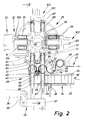
- die Vorrichtung in Seitenansicht, teilweise im Vertikalschnitt,
- Fig. 3
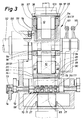
- eine um 90° gegenüber der Darstellung gemäß Fig. 2 versetzte Vorrichtung, teilweise im Vertikalschnitt der Ebene III - III in Fig. 2 bei vergrößertem Maßstab,
- Fig. 4
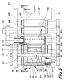
- einen Ausschnitt der Vorrichtung in einer Darstellung entsprechend Fig. 2 bei vergrößertem Maßstab,
- Fig. 5
- ein Aggregat für den Transport einer Materialbahn als Teil der Vorrichtung gemäß Fig. 1 in Draufsicht bzw. im Horizontalschnitt,
- Fig. 6
- einen Schnitt bzw. eine Ansicht in der Ebene VI - VI der Fig. 5 bei vergrößertem Maßstab,
- Fig. 7
- eine Einzelheit entsprechend der Darstellung der Fig. 6 in einer versetzten Ebene VII - VII der Fig. 5,
- Fig. 8
- einen Ausschnitt der Vorrichtung in einer Darstellung entsprechend Fig. 1 mit abgewandelter Einzelheit.
- Fig. 1
- a perspective view of a cigarette packet to be produced on the device shown,
- Fig. 2
- the device in side view, partially in vertical section,
- Fig. 3
- 2, partially in vertical section of the plane III - III in FIG. 2 on an enlarged scale,
- Fig. 4
- 3 shows a section of the device in a representation corresponding to FIG. 2 on an enlarged scale,
- Fig. 5
- 1 shows a unit for the transport of a material web as part of the device according to FIG. 1 in plan view or in horizontal section
- Fig. 6
- 5 shows a section or a view in the plane VI-VI of FIG. 5 on an enlarged scale,
- Fig. 7
- 6 in an offset plane VII - VII of FIG. 5,
- Fig. 8
- a section of the device in a representation corresponding to FIG. 1 with a modified detail.
Die in den Zeichnungen als Ausführungsbeispiel dargestellte Vorrichtung ist besonders vorteilhaft für die Herstellung bzw. für das Einhüllen quaderförmiger Zigaretten-Packungen 10 geeignet. Im einzelnen geht es um die Bildung einer Außenumhüllung 11 als Zellglas, Poly-Folie oder dergleichen.The device shown as an exemplary embodiment in the drawings is particularly advantageously suitable for the production or for wrapping
Die Außenumhüllung 11 besteht aus einem rechteckigen Zuschnitt 12 bzw. 13. Dieser wird in einem ersten Faltschritt U-förmig um die Zigaretten-Packung 10 herumgelegt unter Bildung einer in Bewegungsrichtung vornliegenden Seitenwand 14. Auf der zu dieser gegenüberliegenden weiteren Seitenwand 15 wird eine in Längsrichtung derselben verlaufende Überlappung von entsprechend bemessenen Seitenwandlappen 16 und 17 gebildet. Diese sind im Bereich ihrer Überlappung miteinander verbunden, insbesondere durch Siegeln.The
Eine Bodenwand 18 und eine in gleicher Weise ausgebildete obere Stirnwand 19 der Außenumhüllung 11 sind als Couvert-Faltung ausgebildet. Dabei werden als erstes Seitenendlappen 20 und 21 in Verlängerung der Seitenwandlappen 16, 17 gegen Bodenwand und Stirnwand der Zigaretten-Packung 10 gefaltet. Abschließend werden trapezförmige Längslappen 22, 23 zur Vollendung von Bodenwand 18 und Stirnwand 19 mit Überlappung gegeneinander gefaltet.A
Die in dieser Weise einzuhüllenden Zigaretten-Packungen 10 kommen von einer Verpackungsmaschine (nicht dargestellt). In Dichtlage nebeneinanderliegend werden die Zigaretten-Packungen 10 auf einer Packungsbahn 24 zugefördert. Diese besteht aus einer Unterwand 25, einer Oberwand 26 und Seitenführungen 27. Innerhalb der so ausgebildeten Packungsbahn 24 werden die Zigaretten-Packungen 10 durch Übertragung des Vorschubs von einer Zigaretten-Packung 10 auf die andere taktweise gefördert.The cigarette packs 10 to be wrapped in this way come from a packaging machine (not shown). The cigarette packs 10 are conveyed in a sealing position next to one another on a
Im Bereich einer Einschubstation 28 werden die Zigaretten-Packungen 10 durch Abheben von der Packungsbahn 24 und Aufwärtsbewegung einem in vertikaler Ebene schrittweise drehenden Faltrevolver 29 übergeführt.In the area of an
Der Faltrevolver 29 ist mit jeweils paarweise angeordneten Taschen 30, 31 versehen. In die auf der radial außenliegenden Seite offenliegenden Taschen 30, 31 wird jeweils eine Zigaretten Packung 10 von unten her eingeschoben, und zwar unter Mitnahme eines entsprechend bereitgehaltenen Zuschnitts 12, 13. Dieser legt sich dabei U-förmig um die Zigaretten-Packung 10 herum, ausgehend von der in Bewegungsrichtung vornliegenden Seitenwand 14.The
In den zu zweit parallel zueinander angeordneten Taschen 30, 31 werden die Zigaretten-Packungen 10 längs eines Dreiviertelkreises taktweise gefördert, unter Durchführung der beschriebenen Faltoperationen. Im Bereich einer Ausschubstation 32 werden die mit der fertigen Außenumhüllung 11 versehenen Zigaretten-Packungen 10 wiederum paarweise aus den Taschen 30, 31 aus- und in eine Abförderbahn 33 eingeschoben.In the two
Für die Übergabe der jeweils zwei Zigaretten-Packungen 10 an den Faltrevolver 29 ist im Bereich der Einschubstation 28 ein Doppelschieber 34 mit zwei im Abstand voneinander angeordneten, gemeinsam bewegten Stößeln 35, 36 angeordnet. Ein für die Stößel 35, 36 gemeinsamer Tragkörper 37 wird in geeigneter Weise auf- und abgehend angetrieben, im vorliegenden Falle über einen Schwinghebel 38 mit Lenker 39.For the transfer of the two cigarette packs 10 to the
Die Stößel 35, 36 treten durch schlitzförmige Ausnehmungen 40, 41 in der Unterwand 25 der Packungsbahn 24 hindurch. Die Stößel 35, 36 sind in einem derartigen Abstand voneinander angeordnet, daß zwischen den beiden aus einer Dichtreihe 42 der Zigaretten-Packungen 10 herausgehobenen Zigaretten-Packungen 10 ein Abstand entsprechend den Abmessungen von zwei Zigaretten-Packungen 10 entsteht. Dadurch wird zwischen den einzuhüllenden Zigaretten-Packungen 10 ein ausreichender Abstand hergestellt für die Mitnahme der beiden Zuschnitte 12 und 13 sowie für die Ausführung von Faltschritten im Bereich des Faltrevolvers 29.The
Die Zigaretten-Packungen 10 werden mit den Zuschnitten 12, 13 durch die Stößel 35, 36 bis zu ihrer Endposition innerhalb der Taschen 30, 31 gefördert. Nach Rückkehr in die Ausgangsstellung (bündig mit Unterwand 25) wird die Dichtreihe 42 der Zigaretten-Packungen 10 um einen der Abmessung von zwei Zigaretten-Packungen 10 entsprechenden Weg weitergefördert, so daß eine durchgehende Dichtreihe 42 geschaffen ist unter Anlage an einer Endwandung 43 der Packungsbahn 24. Während des Ausschubs der beiden einzuhüllenden Zigaretten-Packungen 10 wird der nachfolgende Teil der Dichtreihe 42 an einer Weiterbewegung gehindert, und zwar durch Festklemmen von vornliegenden Zigaretten-Packungen 10 an der Oberwand 26 der Packungsbahn 24. Zu diesem Zweck ist ein Teilbereich der Unterwand 25 als Hubplatte 44 ausgebildet. Durch geringfügige Aufwärtsbewegung erfolgt das Festklemmen der beiden vorderen Zigaretten-Packungen 10 und damit ein Fixieren der Dichtreihe 42.The cigarette packs 10 are conveyed with the
Die Zuschnitte 12 und 13 werden jeweils positionsgenau oberhalb der beiden aufwärtsbewegten Zigaretten-Packungen 10 in einer Ebene quer zu deren Bewegungsbahn bereitgehalten. Die Zigaretten-Packungen 10 treten über eine Ausschuböffnung 45, 46 der Oberwand 26 aus. Die Zuschnitte 12, 13 sind oberhalb dieser Ausschuböffnung 45, 46 bereitgehalten.The
Die beiden je einer Zigaretten-Packung 10 zugeordneten Zuschnitte 12, 13 werden von einer gemeinsamen, fortlaufenden Materialbahn 47 aus Verpackungsmaterial (Folie) abgetrennt. Die von einer nicht gezeigten Bobine abschnittsweise abgezogene Materialbahn 47 wird im wesentlichen horizontal, jedenfalls quer zur aufwärtsgerichteten Bewegungsbahn der Zigaretten-Packungen 10 der Einschubstation 28 zugeführt. Zwei angetriebene und entsprechend gesteuerte Zugwalzen 48, 49 besorgen den präzisen Vorschub. Die Materialbahn 47 läuft sodann über mehrere, drehend antreibbare Förderwalzen. Von diesen ist eine an die Zugwalzen 48, 49 anschließende als Messerwalze 50 ausgebildet mit einem umlaufenden Trennmesser 51 und einem feststehenden Gegenmesser 52. Die Messerwalze 50 ist so bemessen, daß in Verbindung mit einer entsprechenden Relativstellung von Trennmesser 51 und Gegenmesser 52 an passender Stelle ein Trennschnitt 53 zur Abtrennung der beiden Zuschnitte 12 und 13 voneinander und danach ein weiterer Trennschnitt 54 zur Abtrennung des (zweiten) Zuschnitts 13 von der Materialbahn 47 ausgeführt werden. Die Messerwalze 50 ist neben dem Trennmesser 51 mit Saugbohrungen 55 versehen, die mittels Saugluft das vordere, freie Ende der nachfolgenden Materialbahn 47 auf der Messerwalze 50 fixieren.The two
Die Materialbahn 47 wird während jedes Arbeitstaktes um einen der Abmessung der beiden Zuschnitte 12 und 13 entsprechenden Bahnabschnitt gefördert. Während des Transports erfolgt die Durchtrennung der Zuschnitte 12, 13 und die Abtrennung von der Materialbahn 47. Im Anschluß an die Messerwalze 50 wird die Materialbahn 47 bzw. werden die Zuschnitte 12, 13 unmittelbar an den Umfang weiterer walzenförmiger Förderorgane übergeben, die die Materialbahn 47 unter starken Umschlingungen in die Faltposition (Fig. 4) fördern.The
Walzenförderer 56 und 57 im Bereich der Einschubstation 28 dienen zugleich als Halteorgane für die Zuschnitte 12, 13 in exakter Relativstellung zur aufwärtsgerichteten Bewegungsbahn der Zigaretten-Packungen 10. Von diesen Walzenförderern 56, 57 werden die Zuschnitte 12, 13 bei der Aufwärtsbewegung der Zigaretten-Packungen 10 schlupfend abgezogen.
Bei dem gezeigten Ausführungsbeispiel bestehen die Walzenförderer 56, 57 aus seitlichen, drehend antreibbaren Saugscheiben 58, 59. Diese sind jeweils an der Außenseite mit antreibbaren Wellenzapfen 60 versehen. Die Saugscheiben 58, 59 sind in ihrer axialen Richtung so bemessen und derart im Abstand voneinander angeordnet, daß lediglich Randstreifen der Materialbahn 47 bzw. der Zuschnitte 12, 13 auf dem Umfang der Saugscheiben 58, 59 aufliegt und durch diese mittels Saugluft gehalten werden. Dieser Randstreifen entspricht dabei der Breite von über die Zigaretten-Packung 10 während dieser Phase hinwegstehenden Teilen der Zuschnitte 12, 13 zur späteren Bildung der Bodenwand 18 und Stirnwand 19.In the embodiment shown, the
Zwischen den seitlichen Saugscheiben 58, 59 sind aufrechte Stützwände 61, 62 bzw. 63, 64 gebildet. Diese sind paarweise den Saugscheiben 58, 59 als feststehende, unbewegliche Ergänzung der Walzenförderer 56, 57 zugeordnet. Die Stützwände 61..64 sind so ausgebildet, daß innen eine spaltförmige Durchtrittsöffnung 65, 66 in Fortsetzung der Ausschuböffnungen 45, 46 für den Durchschub der Zigaretten-Packungen 10 gebildet ist. Die Stützwände 61..64 sind bei dem gezeigten Ausführungsbeispiel mit der Oberwand 26 der Packungsbahn 24 verbunden bzw. bilden einen Teil derselben.
An der Außenseite sind die Stützwände 61..64 so geformt, daß die Zuschnitte 12, 13 im Bereich derselben an abgerundeten bzw. gewölbten Außenflächen anliegen. Konkret sind die Stützwände 61..64 der zylindrischen Gestalt als Teil der Walzenförderer 56, 57 angepaßt. Im Bereich zwischen den Walzenförderern 56, 57 gehen die benachbarten Stützwände 62, 63 fließend in eine kreisbogenförmige Führungsmulde 67 der entsprechend geformten Oberseite der Oberwand 26 über. Die Materialbahn 47 bzw. die Zuschnitte 12, 13 werden unter Anlage an entsprechende Führungsflächen durch diese Führungsmulde 67 hindurchgefördert. In der Endposition sind die Zuschnitte 12, 13 auf den Walzenförderern 56, 57 bzw. den Saugscheiben 58, 59 derselben so fixiert, daß in bezug auf die zugeordneten Zigaretten-Packungen 10 eine geringfügige Außermittigkeit gegeben ist. Wie insbesondere aus Fig. 4 ersichtlich, werden dadurch die Zigaretten-Packungen 10 mit ungleich langen, nach unten weisenden Seitenwandlappen 16, 17 in die Taschen 30, 31 eingefördert.On the outside, the
Zur exakten Führung der Materialbahn 47 bzw. Zuschnitte 12, 13 im Bereich der Einschubstation 28 ist zwischen den Walzenförderern 56, 57, nämlich im Bereich der Führungsmulde 67, ein weiteres Führungs- und Förderorgan angeordnet. Dieses besteht zum einen aus einer im Takt der übrigen Förderorgane drehend angetriebenen Führungswalze 68, die zentrisch in der Führungsmulde 67 gelagert ist. Die Führungswalze 68 ist mit mehreren, parallelen und ringsherum laufenden Eindrehungen 69 versehen. Für die Anlage der Materialbahn 47 sind dadurch mehrere, in Axialrichtung mit Abstand voneinander angeordnete Walzenabschnitte 70 vorgesehen. Diese sind jeweils mit einer an der Umfangsfläche mündenden Saugbohrung 71 ausgestattet, die die Materialbahn 47 bzw. die Zuschnitte 12, 13 auf den Walzenabschnitten 70 fixiert. Die Saugbohrungen 71 sind an eine zentrische Saugleitung 72 angeschlossen, die im Bereich des Drehlagers der Führungswalze 68 über einen Saugring 73 mit einem Saugleitungsanschluß 74 verbunden ist.For the exact guidance of the
Der Führungswalze 68 zugeordnet ist ein feststehender Gegenkörper 75. Dieser ist mittig zwischen den Walzenförderern 56, 57 angeordnet. Der untere Bereich ist bogenförmig ausgebildet und an die Abmessung der Führungswalze 68 angepaßt. Der Gegenkörper 75 ist hier kammartig ausgebildet mit nach beiden Seiten gerichteten Fingern 76, 77. Diese treten in die Eindrehungen 69 zwischen den Walzenabschnitten 70 der Führungswalze 68 ein und bewirken, daß die Materialbahn 47 bei der Vorschubbewegung korrekt geführt wird, nämlich vom Umfang des ersten Walzenförderers 56 an die Führungswalze 68 übergeben und von dieser auf den zweiten Walzenförderer 57 geleitet wird. Der Gegenkörper 75 hat dabei auch Abstreiferfunktion.A fixed
Die Materialbahn (47) bzw. die Zuschnitte (12, 13) umschlingen die Walzenförderer (56, 57) und die Führungswalze (68) um mehr als die Hälfte. Der Trennschnitt (53) zur Teilung der beiden Zuschnitte (12, 13) voneinander liegt im Bereich der Führungswalze (68), etwas außermittig, so daß bei der Übernahme der Zuschnitte (12,13) durch die zugeordneten Zigaretten-Packungen (10) die Zuschnitte (12, 13) schlupfend einerseits von den Walzenförderern (56, 57) und andererseits in entgegengesetzten Richtungen von der Führungswalze (68) abgezogen werden.The material web (47) or the blanks (12, 13) loop around the roller conveyors (56, 57) and the guide roller (68) by more than half. The separating cut (53) for dividing the two blanks (12, 13) lies from one another in the area of the guide roller (68), somewhat off-center, so that when the blanks (12, 13) are taken over by the associated cigarette packs (10), the blanks (12, 13) slip on the one hand from the roller conveyors (56, 57) and on the other hand, be pulled in opposite directions from the guide roller (68).
Der stark geschwungene Verlauf der Materialbahn 47 bzw. der Zuschnitte 12, 13 ist besonders aus Fig. 6 ersichtlich. Durch diese Formgebung der Materialbahn 47 ist es möglich, die gemeinsam auszuschiebenden Zigaretten-Packungen 10 in geringem Abstand voneinander anzuordnen, trotz der beträchtlichen Abmessung der Zuschnitte 12, 13 in Förderrichtung. Die Anordnung der Förderwalzen 50, 56, 57 und 68 relativ zueinander ist derart, daß die Materialbahn 47 unmittelbar von dem Umfang einer Förderwalze an die andere übergeben wird. Jede dieser Förderwalzen ist mit radial gerichteten Saugbohrungen 55 und 71 bzw. 78 und 79 versehen, die jeweils einen in Förderrichtung vornliegenden Randbereich der Materialbahn 47 bzw. der Zuschnitte 12, 13 erfassen und so den Transport sichern. Bei der Übergabe eines Zuschnitts 12, 13 von einer dieser Förderwalzen an die nächste kommen die Saugbohrungen momentan in eine benachbarte Relativstellung (in Fig. 6 beim Walzenförderer 56 und der Führungswalze 68). Während der Phase des Übergangs wird die bis dahin den Zuschnitt 13 haltende Saugbohrung 78 kurzzeitig entlüftet, so daß der Zuschnitt zuverlässig an die nächste Förderwalze übergeben wird. Die Walzenförderer 56, 57 sind dabei jeweils nur mit einzelnen Saugbohrungen 78, 79 im Bereich der Saugscheiben 58, 59 versehen. Die Messerwalze 50 ist mit einer in Axialrichtung durchlaufenden Reihe von Saugbohrungen 55 ausgerüstet (Fig. 5).The strongly curved course of the
Das System der Saugbohrungen ist im wesentlichen in herkömmlicher Weise ausgebildet. Die Saugbohrungen sind dabei mit innerhalb der Förderwalzen achsparallel verlaufenden Saugleitungen 80 verbunden. Diese münden an den Stirnenden der Förderwalzen an unverdrehbar gelagerten Saugscheiben 81, in Fig. 5 anhand des Walzenförderers 56 im Schnitt gezeigt. Die Saugscheiben 81 werden jeweils durch Druckfedern 82 gleitend und dichtend an die zugekehrten Stirnflächen der Förderwalzen gedrückt. Die Saugscheiben 81 sind weiterhin mit kreisförmigen Saugnuten 83 versehen, die zu den Stirnflächen der Förderwalzen offen sind und mit denen die Enden der Saugleitungen 80 während der Drehbewegung der Förderwalzen zeitweilig zur Überdeckung kommen. Während dieser Überdeckungsphase wird Saugluft übertragen. Die Länge der Saugnuten 83 entspricht demnach der Dauer der Saugphase. Benachbart zu den Saugnuten 83, jedoch außerhalb derselben, ist, wo erforderlich, eine Entlüftungsbohrung 84 angebracht, und zwar auf demselben Kreisbogen wie die Saugnuten 83, so daß die Saugleitung 80 während einer kurzen Phase der Drehbewegung mit der Entlüftungsbohrung 84 zur Überdeckung kommt und dadurch die bereits beschriebene Entlüftung der Saugbohrungen bewirkt. Fig. 7 zeigt die Relativstellung der Saugnuten 83 und Entlüftungsbohrungen 84 für die Förderwalzen 50, 56, 57 und 68.The system of suction bores is essentially designed in a conventional manner. The suction bores are axially parallel within the conveyor
Vor dem Einschub der Zigaretten-Packungen 10 in die beiden Taschen 30, 31 des Faltrevolvers 29 treten die Zigaretten-Packungen 10 mit den Zuschnitten 12, 13 durch ein Mundstück hindurch, welches durch feststehende Außenwände 85, 86 einerseits und durch den entsprechend geformten Gegenkörper 75 andererseits gebildet ist.Before the cigarette packs 10 are inserted into the two
In den durch jeweils zwei Taschenwandungen 87, 88 gebildeten Taschen 30, 31 werden die Zigaretten-Packungen 10 so gehalten, daß die Seitenwandlappen 16,17 aus den Taschen 30, 31 herausragen. Unmittelbar im Bereich der Einschubstation 28 treten nun erste Faltorgane in Aktion, nämlich konzentrisch zum Faltrevolver 29 angeordnete und hin- und herschwenkbare Seitenfalter 89 und 90. Durch den Seitenfalter 89 wird zunächst der kürzere, innenliegende Seitenwandlappen 17 der in Drehrichtung des Faltrevolvers 29 rückwärtigen Taschen 30 umgefaltet. Durch entsprechende Schwingbewegung des Seitenfalters 90 wird zugleich der innere Seitenwandlappen 17 der benachbarten Tasche 31 umgefaltet. Bei der nun beginnenden Drehbewegung des Faltrevolvers 29 wird der längere, äußere Seitenwandlappen 16 der Tasche 31 durch die Kante einer ortsfesten äußeren Führungswand 91 des Faltrevolvers 29 umgefaltet. Der entsprechende Seitenwandlappen 17 der Zigaretten-Packung 10 in der benachbarten Tasche 30 wird durch den Seitenfalter 90 in gleicher Weise gefaltet. Die genannten Seitenfalter 89, 90 sind auf einer Revolverwelle 92 des Faltrevolvers 29 gelagert und werden durch Schubstangen 93 schwingend betätigt.The cigarette packs 10 are held in the
Bereits bei der Einschubbewegung der Zigaretten-Packungen 10 mit den Zuschnitten 12, 13 in die Taschen 30, 31 erfolgt der erste Faltvorgang, nämlich das Einfalten der in Einschubrichtung vornliegenden Seitenendlappen 20 durch Faltfinger 94 als seitliche Begrenzung der Taschen 30, 31. Die Faltung erfolgt dabei durch Relativbewegung der Zigaretten-Packungen 10 zu diesen Faltfingern 94. Zur Fixierung der danach seitlich abstehenden Längslappen 22, 23 sind die Faltfinger 94 an den in Drehrichtung des Faltrevolvers 29 weisenden Seitenflächen mit Saugbohrungen 95 versehen. Die Faltfinger 94 bilden zugleich die seitlichen Begrenzungen der Taschen 30, 31. Weitere Saugbohrungen 96 münden im Bereich von Stirnflächen 97 der Faltfinger 94. Durch die Saugbohrungen 96 werden die Zuschnitteile zur Bildung der gegenüberliegenden Seitenendlappen 21 in ihrer quergerichteten Position gehalten. Durch die Saugbohrungen 96 wird zugleich der innenliegende Seitenwandlappen 17 in seiner Position gehalten und damit die überlappende Stellung der beiden Seitenwandlappen 16, 17 stabilisiert. Die Saugbohrungen 95, 96 sind an ein System von Saugkanälen 98 innerhalb des Faltrevolvers angeschlossen. Über einen zentralen Segmentring 99 werden die Saugkanäle 98 und damit die Saugbohrungen 95, 96 in der beschriebenen Weise mit Saugluft versorgt.Already during the insertion movement of the cigarette packs 10 with the
Im Bereich einer ersten Siegelstation 100 werden die einander überlappenden Seitenwandlappen 16, 17 durch ein gabelförmiges Siegelorgan 101 unter Anwendung von Wärme und Druck gesiegelt. Dieser Vorgang wiederholt sich nach dem Weiterschalten des Faltrevolvers in einer zweiten Siegelstation 102 mit einem weiteren Siegelorgan 103.In the area of a
In der nach erneuter Schaltung des Faltrevolvers 29 erreichten Ausschubstation 32 werden die Zigaretten-Packungen 10 durch einen gemeinsamen winkelförmigen Ausschieber 104 aus den Taschen 30, 31 heraus- und in die Abförderbahn 33 eingeschoben. Beim Austritt der Zigaretten-Packungen 10 aus den Taschen 30, 31 erfolgt das Umfalten der in Radialrichtung außenliegenden Seitenendlappen 21 durch feststehende Faltdaumen 105 an der Eintrittsseite der Abförderbahn 33.In the
Während des Transports der Zigaretten-Packungen 10 in der Abförderbahn 33 werden die nun noch seitlich überstehenden Längslappen 22, 23 gefaltet, und zwar durch bekannte Faltweichen oder andere Faltorgane.During the transport of the cigarette packs 10 in the
Die in Fig. 8 gezeigte Lösung entspricht weitgehend der beschriebenen. Gegenüber den Einzelheiten gemäß Fig. 2 und 4 sind bei Fig. 8 in der Bewegungsbahn der Zigaretten-Packungen 10 zu den Taschen 30, 31 des Faltrevolvers 29 feststehende Faltdaumen 110 zu beiden Seiten der Bewegungsbahn angeordnet, derart, daß bei der Vorbeibewegung der Zigaretten-Packungen 10 die in Bewegungsrichtung vornliegenden Seitenendlappen 20 vorgefaltet werden. Der Gegenkörper 75 sowie die seitlich angeordneten Außenwände 85 und 86 sind entsprechend länger ausgebildet.The solution shown in Fig. 8 largely corresponds to that described. Compared to the details according to FIGS. 2 and 4, in FIG. 8, in the movement path of the cigarette packs 10 to the
Die Förderorgane, nämlich die Zugwalzen (48, 49), die Messerwalze (50), die Walzenförderer (56, 57) und die Führungswalze (68) sind seitlich in Tragwangen (106, 107) gelagert. Der Antrieb erfolgt über eine Antriebswelle (108) über eine Mehrzahl von in sinnvoller Weise miteinander kämmenden Zahnrädern (109).The conveying elements, namely the pull rollers (48, 49), the knife roller (50), the roller conveyors (56, 57) and the guide roller (68) are mounted laterally in carrying cheeks (106, 107). The drive takes place via a drive shaft (108) via a plurality of gearwheels (109) which mesh in a meaningful manner.
Claims (20)
- Process for wrapping packs (10), especially cuboid cigarette packs, into blanks (12, 13) which, during the pushing of the packs (10) into pockets (30, 31) of a folding turret (29), are laid round the packs (10) in a U-shaped manner and the projecting tabs of which are then folded, the folding turret (29) being fed a plurality of, in particular two, packs (10) parallel next to one another and the blanks (12, 13) being separated from a common web of material (47) and being conveyed in the correct position into the path of movement of the packs (10), characterized in that the packs (10) are held ready - relative to the folding turret (29) - in a common, transverse-axial plane and parallel next to one another in the circumferential direction and, in this plane, are pushed into the corresponding pockets (30, 31) of the folding turret (29).
- Process according to Claim 1, characterized in that the packs (10) are pushed simultaneously into the pockets (30, 31) of the folding turret (29) and for this purpose are pushed out of a close-packed row (42) of packs (10) in the transverse direction relative to these, especially from the bottom upwards.
- Process according to Claim 1 or 2, characterized in that the blanks (12, 13) or the web portion for forming these is deformed in the region of the packs (10) to and fro, especially in a wave-shaped manner, to reduce the necessay distance between the packs (10) to be wrapped simultaneously, a distance of preferably two packs being formed between the two packs (10) to be wrapped simultaneously.
- Process according to one or more of Claims 1 to 3, characterized in that a material portion corresponding to the dimension of two blanks (12, 13) and belonging to the web of material (47) is respectively conveyed in the correct position, separated from the web of material (47) and severed to form the two blanks (12, 13).
- Process according to one or more of Claims 1 to 4, characterized in that, during the transport of the web of material (47), the blanks (12, 13) are separated from the latter and severed.
- Apparatus for wrapping packs (10), especially cuboid cigarette packs, into blanks (12, 13) which, during the pushing of the packs (10) into pockets (30, 31) of a folding turret (29), can be folded round the packs (10) in a U-shaped manner and which can be ready-folded in the region of the folding turret (29), the folding turret (29) being able to be fed a plurality of, in particular two, packs (10) parallel next to one another, characterized in that the pockets (30, 31) for receiving the packs (10) to be fed next to one another are arranged in the folding turret (29) in a transverse-axial plane and parallel next to one another in the circumferential direction.
- Apparatus according to Claim 6, characterized in that the two packs (10) to be wrapped, in particular, simultaneously are pushed from a horizontal pack track (24) out of a close-packed row (42) in the upward direction by tappets (35, 36) into the preferably two pockets (30, 31) of the folding turret (29).
- Apparatus according to Claim 7, characterized in that the packs (10) to be wrapped simultaneously are, within the close-packed row (42), at a distance from one another which corresponds to the width of two packs.
- Apparatus according to one or more of Claims 6 to 8, characterized in that the folding turret (29) has four pairs of pockets (30, 31) arranged parallel to and at a distance from one another and is movable intermittently respectively over a quarter circle.
- Apparatus according to one or more of Claims 6 to 9, characterized in that, for the simultaneous wrapping of the plurality of, in particular two, packs (10), a web portion, corresponding to the length of a plurality of blanks (12, 13), of a common web of material (47) can be conveyed by conveying members, in particular rotatable conveying rollers, to the packs (10), the web portion, during conveyance by the conveying members, preferably being able to be separated into the individual blanks (12, 13) and from the web of material (47), especially as a result of the design of at least one conveying member as a knife roller (50) with a rotating severing knife (51) and a stationary counter-knife (52).
- Apparatus according to Claim 10, characterized in that a web portion of the two blanks (12, 13) is guided round several conveying rollers in a wave-shaped manner, a roller conveyor (56, 57) being arranged respectively in the region of the path of movement of the cigarette packs (10) and serving for fixing a blank (12, 13) in the correct position.
- Apparatus according to Claim 11, characterized in that the roller conveyors (56, 57) arranged in the region of the cigarette packs (10) to be wrapped have laterally arranged, rotatably driven suction discs (58, 59), on the periphery of which the blanks (12, 13) are held, especially by means of suction air, over an edge region extending outside the cigarette packs (10) to be wrapped.
- Apparatus according to Claim 12, characterized in that the suction discs (58, 59) are arranged at the ends of shaft journals (60) and in that between the suction discs (58, 59) belonging to the same roller conveyor (56, 57) are arranged stationary non-rotatable supporting walls (61, 62 and 63, 64) for supporting the blanks (12, 13) in the region between the suction discs (58, 59).
- Apparatus according to Claim 13, characterized in that the supporting walls (61 to 64) respectively delimit a slot-shaped passage orifice (65, 66) for the cigarette packs (10), above the supporting walls (61 to 64) the blanks (12, 13) extending transversely relative to the direction of movement of the cigarette packs (10).
- Apparatus according to Claim 13 or 14, characterized in that the supporting walls (61 to 64) are equipped with curved or arcuate outer faces which serve for the resting and guidance of the web of material (47) or of the blanks (12, 13), the supporting walls (61 to 64) being connected to an upper wall (26) of a pack track (24), and the outer faces of the supporting walls (61 to 64) forming with the top side of the upper wall (26) continuous, mutually co-ordinated guide faces for the web of material (47) or for the blanks (12, 13).
- Apparatus according to Claim 11 and one or more of the further claims, characterized in that arranged centrally between the respective roller conveyors (56, 57) assigned to a cigarette pack (10) to be wrapped is a further conveying member for the web of material (47) or for the blanks (12, 13), especially a rotary-driven guide roller (68), by means of which the web of material (47) can be transferred from one roller conveyor (56) to the next roller conveyor (57) during the advance.
- Apparatus according to Claim 16, characterized in that assigned to the guide roller (68) is a stationary guide member, especially a counterbody (75), which is arranged between the roller conveyors (56, 57) and which, as a result of an appropriate design, assists the guidance of the web of material (47) in the region of the roller conveyors (56, 57) and of the guide roller (68).
- Apparatus according to Claim 17, characterized in that the counterbody (75) is equipped in the lower region with fender members, especially with fingers (76, 77) which are directed on two sides and which project into recesses (69) of the guide roller (68).
- Apparatus according to Claim 6 and one or more of the further claims, characterized in that, after the cigarette packs (10) together with blank (12, 13) have entered a pocket (30, 31) of the folding turret (29), side folders (89, 90) pivotable concentrically relative to the folding turret are movable relative to the folding turret (29) in such a way that inner side-wall tabs (17) projecting beyond the cigarette pack (10) in the radial direction can be folded.
- Apparatus according to Claim 19, characterized in that, during the further movement of the folding turret, one of the side folders (90) causes an outer side-wall tab (16) of the cigarette pack (10) located at the rear in the conveying direction to be folded round.
Applications Claiming Priority (2)
| Application Number | Priority Date | Filing Date | Title |
|---|---|---|---|
| DE3728716 | 1987-08-28 | ||
| DE3728716A DE3728716C2 (en) | 1987-08-28 | 1987-08-28 | Method for wrapping cuboid objects, in particular cigarette packs, and device for carrying out the method |
Publications (3)
| Publication Number | Publication Date |
|---|---|
| EP0304736A2 EP0304736A2 (en) | 1989-03-01 |
| EP0304736A3 EP0304736A3 (en) | 1990-03-14 |
| EP0304736B1 true EP0304736B1 (en) | 1994-06-08 |
Family
ID=6334674
Family Applications (1)
| Application Number | Title | Priority Date | Filing Date |
|---|---|---|---|
| EP88113100A Expired - Lifetime EP0304736B1 (en) | 1987-08-28 | 1988-08-12 | Method and device for enveloping, especially cigarette packages |
Country Status (7)
| Country | Link |
|---|---|
| US (1) | US4909020A (en) |
| EP (1) | EP0304736B1 (en) |
| JP (1) | JPH0829763B2 (en) |
| CN (1) | CN1015973B (en) |
| BR (1) | BR8804400A (en) |
| CA (1) | CA1330754C (en) |
| DE (2) | DE3728716C2 (en) |
Families Citing this family (19)
| Publication number | Priority date | Publication date | Assignee | Title |
|---|---|---|---|---|
| IT1234022B (en) * | 1989-03-07 | 1992-04-24 | Gd Spa | WRAPPING MACHINE OF SUBSTANTIALLY PARALLELEPIPED PRODUCTS |
| IT1246012B (en) † | 1991-06-21 | 1994-11-07 | Gd Spa | WRAPPING METHOD AND DEVICE FOR THE PRODUCTION OF TUBULAR PRODUCT WRAPS. |
| IT1252425B (en) * | 1991-07-16 | 1995-06-14 | Gd Spa | METHOD AND DEVICE FOR THE CONTEMPORARY CLOSURE OF PAIRS OF ENVELOPES |
| GB2290533B (en) * | 1991-08-01 | 1996-02-28 | Molins Plc | Wrapping articles |
| DE4200921B4 (en) * | 1992-01-16 | 2005-12-22 | Focke & Co.(Gmbh & Co. Kg) | Method for producing packaging from two part packs and device for producing such packagings |
| DE4332810A1 (en) * | 1993-09-27 | 1995-03-30 | Focke & Co | Packaging machine for the manufacture of cigarette packs |
| IT1279221B1 (en) * | 1994-01-20 | 1997-12-09 | Gd Spa | METHOD AND PACKAGING MACHINE FOR THE FORMATION OF DOUBLE PACKAGES FOR CIGARETTES |
| IT1306254B1 (en) * | 1995-05-05 | 2001-06-04 | Gd Spa | METHOD AND MACHINE FOR PACKAGING PRODUCTS |
| DE10000798A1 (en) * | 2000-01-11 | 2001-07-12 | Focke & Co | Device for producing packs of cigarettes |
| DE10123804A1 (en) * | 2001-05-16 | 2002-11-28 | Christian Senning Verpackungsm | Method and device for simultaneous packaging on more than one packaging line |
| ITBO20030706A1 (en) * | 2003-11-21 | 2005-05-22 | Gd Spa | PRODUCT WRAPPING UNIT. |
| ITBO20050595A1 (en) * | 2005-10-06 | 2006-01-05 | Gd Spa | METHOD AND MACHINE FOR THE WRAPPING OF A PRODUCT IN AT LEAST ONE SHEET OF PAPER |
| CN100494003C (en) * | 2006-12-20 | 2009-06-03 | 黄吉全 | Reciprocating action traction mechanism for 3D transparent film packing machine |
| IT1397936B1 (en) | 2010-01-26 | 2013-02-04 | Gima Spa | PACKING MACHINE AND METHOD FOR PACKAGING SMOKE ITEMS. |
| DE102011114522A1 (en) * | 2011-09-29 | 2013-04-04 | Focke & Co. (Gmbh & Co. Kg) | Method and apparatus for producing a package for a group of smokable articles |
| DE102011122327A1 (en) * | 2011-12-23 | 2013-06-27 | Focke & Co. (Gmbh & Co. Kg) | Method and device for producing shrink-wrapped packages |
| BR112017008204B1 (en) * | 2014-10-31 | 2022-07-19 | Cps Company S.R.L | PACKAGING MACHINE WITH A HORIZONTAL SHAFT CAROUSEL, PARTICULARLY FOR PACKAGING PAPER ROLLS OR PAPER NAPKIN PACKAGING OR OTHER SOLID PRODUCTS OF VARIABLE SIZE |
| CN110733696B (en) * | 2019-10-15 | 2024-01-02 | 上海烟草机械有限责任公司 | Tobacco bale packaging device and method |
| CN111731574B (en) * | 2020-06-12 | 2024-03-08 | 红云红河烟草(集团)有限责任公司 | Cigarette strip arranging equipment for cigarette packaging machine |
Family Cites Families (13)
| Publication number | Priority date | Publication date | Assignee | Title |
|---|---|---|---|---|
| DE623446C (en) * | ||||
| GB479130A (en) * | 1936-08-01 | 1938-02-01 | George Daniel Horgan | Improvements in and relating to machines for packeting cigarettes and the like |
| US2686393A (en) * | 1952-02-04 | 1954-08-17 | Forgrove Mach | End tucker and folder mechanism for wrapping machines |
| US2720738A (en) * | 1954-07-26 | 1955-10-18 | Stephano Brothers | Package wrapping machine |
| DE1117477B (en) * | 1959-07-13 | 1961-11-16 | Theegarten Franz | Candy packaging machine with two packing heads |
| GB1094351A (en) * | 1964-06-04 | 1967-12-13 | Schmermund Alfred | Improvements in or relating to wrapping machines |
| US3590556A (en) * | 1968-01-05 | 1971-07-06 | Heinz Focke | Machine for packing of cigarettes in soft packets |
| US3660961A (en) * | 1970-06-22 | 1972-05-09 | Robert H Ganz | Packaging machine and method |
| DE2810586A1 (en) * | 1978-03-11 | 1979-09-20 | Focke Pfuhl Verpack Automat | METHOD AND DEVICE FOR INSERTING PARTICULAR GROUPS OF CIGARETTES IN A CIGARETTE PACKAGE |
| DE2906204A1 (en) * | 1979-02-17 | 1980-09-04 | Focke & Co | DEVICE FOR COVERING OBJECTS, IN PARTICULAR CIGARETTE GROUPS |
| US4448008A (en) * | 1981-11-09 | 1984-05-15 | Liquipak International, Inc. | Multiple mandrel carton erecting, filling and sealing machine with two-stage loading |
| DE3332950A1 (en) * | 1983-09-13 | 1985-03-28 | Focke & Co, 2810 Verden | METHOD AND DEVICE FOR ENHANCING CIGARETTE PACKS IN FILM CUTS |
| DE3545884C2 (en) * | 1985-12-23 | 1998-10-22 | Focke & Co | Device for producing (cigarette) packs from at least one foldable blank |
-
1987
- 1987-08-28 DE DE3728716A patent/DE3728716C2/en not_active Expired - Fee Related
-
1988
- 1988-08-12 EP EP88113100A patent/EP0304736B1/en not_active Expired - Lifetime
- 1988-08-12 DE DE3850004T patent/DE3850004D1/en not_active Expired - Fee Related
- 1988-08-24 US US07/235,856 patent/US4909020A/en not_active Expired - Lifetime
- 1988-08-26 CA CA000575831A patent/CA1330754C/en not_active Expired - Fee Related
- 1988-08-29 JP JP63214765A patent/JPH0829763B2/en not_active Expired - Fee Related
- 1988-08-29 CN CN88106286A patent/CN1015973B/en not_active Expired
- 1988-08-29 BR BR8804400A patent/BR8804400A/en not_active IP Right Cessation
Also Published As
| Publication number | Publication date |
|---|---|
| CN1033033A (en) | 1989-05-24 |
| EP0304736A3 (en) | 1990-03-14 |
| DE3850004D1 (en) | 1994-07-14 |
| DE3728716C2 (en) | 1999-10-07 |
| CA1330754C (en) | 1994-07-19 |
| CN1015973B (en) | 1992-03-25 |
| US4909020A (en) | 1990-03-20 |
| JPS6470322A (en) | 1989-03-15 |
| DE3728716A1 (en) | 1989-03-09 |
| EP0304736A2 (en) | 1989-03-01 |
| BR8804400A (en) | 1989-03-28 |
| JPH0829763B2 (en) | 1996-03-27 |
Similar Documents
| Publication | Publication Date | Title |
|---|---|---|
| EP0304736B1 (en) | Method and device for enveloping, especially cigarette packages | |
| EP0226872B1 (en) | Device for making (cigarette) packages from at least one foldable blank | |
| EP0386524B1 (en) | Device for packaging objects of different size | |
| EP0275481B1 (en) | Method and device for packaging paper handkerchiefs | |
| EP0197368B1 (en) | Method and apparatus for packaging cigarettes in particular | |
| EP0078066B1 (en) | Apparatus for packaging cigarettes or similar articles | |
| DE2425969C2 (en) | ||
| DE2840850C2 (en) | ||
| DE2442055C3 (en) | Method and device for manufacturing and filling a packet of cigarettes | |
| EP1067049B1 (en) | Method and device for making packs | |
| DE2440006A1 (en) | PROCESS AND DEVICE FOR MANUFACTURING AND FILLING FOLDABLE BOXES FROM FOLDABLE MATERIAL, PREFERABLY FOR CIGARETTES | |
| DE2447917C2 (en) | Device for making collars for use in the opening of rigid cigarette packets with flap lids | |
| EP0071736A1 (en) | Packaging device for forming cut sheets and feeding the same to a packaging station | |
| DE4338945A1 (en) | Method and device for producing tubular wraps from weldable material | |
| DE2407767B2 (en) | METHOD AND DEVICE FOR IMPACTING GROUPS OF CIGARETTES | |
| DE3824316A1 (en) | METHOD AND DEVICE FOR PRODUCING A SQUARE PACK | |
| DE19504594B4 (en) | Packaging line for the production of double packs | |
| DE19746141A1 (en) | Method and device for wrapping articles of the tobacco processing industry into packaging material blanks | |
| DE2624812A1 (en) | WRAPPING MACHINE | |
| DE1146801B (en) | Method and apparatus for making a sealed wrap-around package | |
| DE4118763A1 (en) | METHOD FOR PRODUCING TUBULAR COVERS | |
| DE2329534C3 (en) | Device for the continuous wrapping of sweets or similar small parts | |
| DE3608250A1 (en) | DEVICE FOR FEEDING PACKAGING MEANS TO PACKING MACHINES | |
| DE2454289A1 (en) | PACKAGING DEVICE | |
| DE4001587C1 (en) | Feed magazine for cigarette packing machine - gathers cigarettes in pockets on conveyor belt |
Legal Events
| Date | Code | Title | Description |
|---|---|---|---|
| PUAI | Public reference made under article 153(3) epc to a published international application that has entered the european phase |
Free format text: ORIGINAL CODE: 0009012 |
|
| AK | Designated contracting states |
Kind code of ref document: A2 Designated state(s): DE FR GB IT |
|
| PUAL | Search report despatched |
Free format text: ORIGINAL CODE: 0009013 |
|
| AK | Designated contracting states |
Kind code of ref document: A3 Designated state(s): DE FR GB IT |
|
| 17P | Request for examination filed |
Effective date: 19900911 |
|
| 17Q | First examination report despatched |
Effective date: 19920909 |
|
| GRAA | (expected) grant |
Free format text: ORIGINAL CODE: 0009210 |
|
| AK | Designated contracting states |
Kind code of ref document: B1 Designated state(s): DE FR GB IT |
|
| GBT | Gb: translation of ep patent filed (gb section 77(6)(a)/1977) |
Effective date: 19940614 |
|
| REF | Corresponds to: |
Ref document number: 3850004 Country of ref document: DE Date of ref document: 19940714 |
|
| ITF | It: translation for a ep patent filed |
Owner name: STUDIO JAUMANN |
|
| ET | Fr: translation filed | ||
| PLBE | No opposition filed within time limit |
Free format text: ORIGINAL CODE: 0009261 |
|
| STAA | Information on the status of an ep patent application or granted ep patent |
Free format text: STATUS: NO OPPOSITION FILED WITHIN TIME LIMIT |
|
| 26N | No opposition filed | ||
| REG | Reference to a national code |
Ref country code: GB Ref legal event code: IF02 |
|
| PGFP | Annual fee paid to national office [announced via postgrant information from national office to epo] |
Ref country code: FR Payment date: 20020808 Year of fee payment: 15 |
|
| PG25 | Lapsed in a contracting state [announced via postgrant information from national office to epo] |
Ref country code: FR Free format text: LAPSE BECAUSE OF NON-PAYMENT OF DUE FEES Effective date: 20040430 |
|
| REG | Reference to a national code |
Ref country code: FR Ref legal event code: ST |
|
| PGFP | Annual fee paid to national office [announced via postgrant information from national office to epo] |
Ref country code: GB Payment date: 20040811 Year of fee payment: 17 |
|
| PGFP | Annual fee paid to national office [announced via postgrant information from national office to epo] |
Ref country code: DE Payment date: 20040819 Year of fee payment: 17 |
|
| PG25 | Lapsed in a contracting state [announced via postgrant information from national office to epo] |
Ref country code: IT Free format text: LAPSE BECAUSE OF NON-PAYMENT OF DUE FEES;WARNING: LAPSES OF ITALIAN PATENTS WITH EFFECTIVE DATE BEFORE 2007 MAY HAVE OCCURRED AT ANY TIME BEFORE 2007. THE CORRECT EFFECTIVE DATE MAY BE DIFFERENT FROM THE ONE RECORDED. Effective date: 20050812 Ref country code: GB Free format text: LAPSE BECAUSE OF NON-PAYMENT OF DUE FEES Effective date: 20050812 |
|
| PG25 | Lapsed in a contracting state [announced via postgrant information from national office to epo] |
Ref country code: DE Free format text: LAPSE BECAUSE OF NON-PAYMENT OF DUE FEES Effective date: 20060301 |
|
| GBPC | Gb: european patent ceased through non-payment of renewal fee |
Effective date: 20050812 |