EP0125156A1 - Cascaded multiplier using a set of elementary operators - Google Patents
Cascaded multiplier using a set of elementary operators Download PDFInfo
- Publication number
- EP0125156A1 EP0125156A1 EP84400657A EP84400657A EP0125156A1 EP 0125156 A1 EP0125156 A1 EP 0125156A1 EP 84400657 A EP84400657 A EP 84400657A EP 84400657 A EP84400657 A EP 84400657A EP 0125156 A1 EP0125156 A1 EP 0125156A1
- Authority
- EP
- European Patent Office
- Prior art keywords
- operator
- bits
- register
- multiplier
- signal
- Prior art date
- Legal status (The legal status is an assumption and is not a legal conclusion. Google has not performed a legal analysis and makes no representation as to the accuracy of the status listed.)
- Granted
Links
Images


Classifications
-
- G—PHYSICS
- G06—COMPUTING; CALCULATING OR COUNTING
- G06F—ELECTRIC DIGITAL DATA PROCESSING
- G06F7/00—Methods or arrangements for processing data by operating upon the order or content of the data handled
- G06F7/38—Methods or arrangements for performing computations using exclusively denominational number representation, e.g. using binary, ternary, decimal representation
- G06F7/48—Methods or arrangements for performing computations using exclusively denominational number representation, e.g. using binary, ternary, decimal representation using non-contact-making devices, e.g. tube, solid state device; using unspecified devices
- G06F7/52—Multiplying; Dividing
- G06F7/523—Multiplying only
- G06F7/533—Reduction of the number of iteration steps or stages, e.g. using the Booth algorithm, log-sum, odd-even
- G06F7/5334—Reduction of the number of iteration steps or stages, e.g. using the Booth algorithm, log-sum, odd-even by using multiple bit scanning, i.e. by decoding groups of successive multiplier bits in order to select an appropriate precalculated multiple of the multiplicand as a partial product
- G06F7/5336—Reduction of the number of iteration steps or stages, e.g. using the Booth algorithm, log-sum, odd-even by using multiple bit scanning, i.e. by decoding groups of successive multiplier bits in order to select an appropriate precalculated multiple of the multiplicand as a partial product overlapped, i.e. with successive bitgroups sharing one or more bits being recoded into signed digit representation, e.g. using the Modified Booth Algorithm
- G06F7/5338—Reduction of the number of iteration steps or stages, e.g. using the Booth algorithm, log-sum, odd-even by using multiple bit scanning, i.e. by decoding groups of successive multiplier bits in order to select an appropriate precalculated multiple of the multiplicand as a partial product overlapped, i.e. with successive bitgroups sharing one or more bits being recoded into signed digit representation, e.g. using the Modified Booth Algorithm each bitgroup having two new bits, e.g. 2nd order MBA
Definitions
- the present invention relates to multipliers of the cascade type using a set of elementary operators of the same type.
- Each of these elementary operators makes it possible to quickly multiply a binary number (multiplicand) by a small part of another binary number (multiplier).
- multiplicand binary number
- multiplier binary number
- a partial multiplication of rank j between a multiplicand X and a group of two bits Y 2j + 1 Y 2j of the multiplier is done by adding to the previous intermediate result I j-1 one of the five numbers 0, X, 2X, -X, -2X, and by shifting the result S j of this operation by two bits to the right to obtain a new intermediate result 1 1 .
- the choice between these five numbers is made according to the value of the two bits Y 2j + 1 , Y 2j , and of the bit Y 2j + 1 of the previous group, according to the following table:
- the elementary operator represented in FIG. 1 makes it possible to carry out such a partial multiplication between a number X comprising seven bits (including the sign) and two bits Y 2j + 1 and Y 2j of a number Y, ie a 7x2 multiplication with conservation of the sign.
- the operator of FIG. 1 comprises three input registers 101, 102, 103 which make it possible to receive the input data.
- the register 101 includes seven boxes which firstly store the most significant bits of Y not used in the operator j or in those which precede it.
- the boxes freed by the use of the bits of Y make it possible to store the least significant bits of the sum S., which no longer intervene in subsequent partial calculations due to the right shift in the Booth algorithm.
- the register is provided with an output on which there is a copy of the input after the clock step H applied to the register by four delay devices 104 to 107 in series intended to improve the behavior of the circuit.
- the figure represents the case where there are at the input, and therefore at the output, of the register the six most significant bits of Y.
- the register 102 includes nine boxes which make it possible to store the nine most significant bits of the intermediate result I j-1 . This is obtained by shifting two bits to the right of the sum S j-1 at the output of the previous stage and adding two most significant bits equal to the most significant bit of S j-1 . The two least significant bits which overflow in this offset are stored in the register 101 where they replace Y 2j and Y 2j + 1 which arrive in the operator with other inputs.
- the register 102 is also provided with an output which copies its input under the command of H at the output of the delay device 104.
- the register 103 includes ten boxes which make it possible to store the seven bits of the number X, as well as three additional bits. These additional bits include a least significant bit, said to cut. The other two additional bits are two most significant bits which copy the sign bit of X and make it possible during operations to keep this sign. Indeed the 2X (or -2X) operation results in a shift of one bit to the left, and it is moreover necessary to provide for the case where the addition of the signs delivers a carry and therefore requires yet another bit to left.
- This register 103 is also provided with an output which copies its input under the command of H at the output of the delay device 105.
- This output from register 103 is applied to a computing device 108 followed by a multiplexer 109.
- This computing device performs on all ten bits the operations X (direct transfer), X (bit-to-bit complementation of X), 2X (one bit shift to the left), and 2X (complementation followed by a left shift).
- Multiplexer 109 selects the result of one of these four operations under the control of two binary signals which respectively represent Y 2j + 1 and B. These signals are obtained in a manner described below.
- the multiplexer is designed to select only the nine most significant bits, thereby eliminating the cross-over bit which was used in the multiplication by 2 and which is then no longer useful.
- the number at the output of the multiplexer 109 is added to I j-1 , available at the output of the register 102, in a nine-bit adder 110.
- This adder is provided with an input and a carry output.
- adding 1 by the carry input gives -X and -2X in addition to 2, which is the code used.
- the output of the adder, and I j-1, are applied to a multiplexer 111 which selects one of these two signals under control of the signal A, obtained as explained later, and outputs the S signal. .
- the two bits Y 2j-1 and Y 2j coming from the previous stage, are applied to an OR-exclusive gate 112 which delivers the signal B defined above.
- This signal B is stored in a master-slave flip-flop 113 to be applied to the multiplexer 109. This flip-flop is controlled by the clock H at the output of the delay device 107.
- the bit Y 2j + 1 from the previous stage is stored in a master-slave flip-flop 114 to be applied to the multiplexer 109.
- This flip-flop is controlled by the clock H directly.
- the two bits Y 2j and Y 2j + 1 are also applied to an exclusive OR gate 115 whose output is connected to an OR gate 116.
- the other input of this gate receives the signal B, and its output delivers the signal A defined above.
- This signal A is stored in a master-slave flip-flop 117 to be applied to the multiplexer 111. This flip-flop is controlled by the clock H at the output of the delay device 106.
- the signals X and Y 2j + 1 necessary for the next stage, are available at the output of the register 103 and the flip-flop 114, with the delay of a clock step which corresponds to the loading of the register and the flip-flop.
- the same is true for the signals Y 2j + 2 and Y 2j + 3 (contained in Y) and Si.
- X has been represented on nine bits, which includes the two bits of sign SX.
- the cross bit R is not available, because there is no use in transmitting it.
- Such an operator can be integrated in a pre-distributed integrated circuit of commerce, contained in a single box.
- the invention proposes a cascade type multiplier using a set of elementary operators, each elementary operator having a first register Y for receiving and delivering a first signal of at least two bits and at most m bit (m 7 ), a second register RI to receive an intermediate signal of n bits, a third register X to receive a multiplicand signal of n bits and a cross-bit and to deliver this multiplicand signal, decoding circuits D and Q to receive a multiplier signal of three bits and deliver the most significant bit of this signal, a nine-bit adder provided with a carry-in input and a carry-out output, and a circuit S for delivering a nine-bit multiplication signal obtained according to the Booth algorithm between the multiplicand, the intermediate signal and the multiplier, mainly characterized in that, to carry out at least one multiplication between a multiplicand of 2 (n-1) bits and a multiplier of qu other bits, it comprises a first stage comprising a first operator and a second operator and a second stage comprising
- FIG. 2 shows the first stage of a 16x16 multiplier between two signed integers.
- This multiplier therefore performs a 16 ⁇ 2 multiplication between a number X comprising 16 bits X 0 to X 15 , and the first two bits Y 0 and Y of a number Y comprising 16 bits Y 0 to Y 15 .
- This stage comprises two identical operators numbered 0 and 1.
- the internal diagram of these operators is that of FIG. 1 and to facilitate the understanding of the drawing, the input and output circuits are represented diagrammatically by dividing into two parts some of the them (X, Y, 110).
- the operator who works on the least significant of the multiplicand, receives on its input register X the nine least significant bits X 0 to X 8 applied to the inputs of the X register other than that of overlap.
- the input R of the cross-over bit is kept at zero to have a least significant bit at zero in the case of a left shift.
- the operator 0 also receives on its input register RI the nine least significant bits I 0 to I 8 of the intermediate result of the preceding stage, which in this case are at zero since we describe the first stage.
- the first two least significant bits Y o and Y of the multiplier (actually used in this stage) are applied to the various decoding circuits detailed in FIG. 1 and gathered in FIG. 2 in an input circuit called D.
- Y I is also applied to the retaining input of the adder of operator 0.
- Circuit D should also receive a bit Y -1 . Since this does not exist, we substitute a Q bit which is kept at zero.
- Operator 1 which works on the most significant of the multiplicand, receives on its input register X the eight most significant bits X 8 to X 15 .
- X 9 to X 15 are applied to the seven least significant entries and X 15 , which represents the sign, is copied to the two most significant entries for the reasons given in the description of the operator.
- X 8 is applied to the input of the cross-over bit, which explains more particularly the interest of this bit. Indeed if one carries out a shift on the left (representing a multiplication by 2), it is necessary to have the preceding bit on the right since this shift operates on the totality of the number, which is present in two pieces in the two operators.
- the operator 1 also receives on its input register RI the nine most significant bits 1 9 to 1 17 (in this case zero), and on its input register Y the seven most significant bits Y 9 to Y 15 , which are transmitted on the output of this register.
- bits Y 0 and Y 1 are applied to operator 1 in the same way as to operator 0, except for the incoming carry which receives the outgoing carry bit from l operator 0, which ensures continuity between the two pieces of the multiplication.
- this operator 1 we find, in addition to Y 9 to Y 15 already seen, the seven most significant bits X 9 to X 15 and the two additional sign bits, the nine most significant bits S 1 0 to S 1 8 of the result of the 16x2 multiplication, and the bit Y 1 .
- the carry output is available, but is not useful here since it represents the sign of the result, which is already contained at least once in the number output from S.
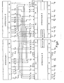
- Figure 3 There is shown in Figure 3 the cascading of a second stage comprising two operators 2 and 3, with the first stage of Figure 1, shown partially, to be able to perform a 16x4 multiplication.
- This second stage therefore uses the three bits Y 1 to Y 3 of the multiplier, which are applied to the circuits D of the two operators, with Y 3 applied in addition to the carry input of operator 2.
- Y 2 and Y 3 are taken at the output of the register Y of the operator 0, and in the version represented Y 1 at the output respectively of the two circuits Q of the operators 0 and 1.
- Possible variants would consist in connecting the output of one of these circuits Q to two corresponding inputs of circuits D.
- the outputs of the X registers of the first stage are directly connected to the inputs of the X registers of the second stage, since the multiplicand is transmitted without change along the stages with simply the delay d0 at each stage. Likewise, the input R of operator 2 is kept at zero.
- the intermediate result corresponding to the multiplication by one digit of the multiplier must be shifted by one digit to the right before being added to the next intermediate result. So the number formed of bits S 0 0 to S 1 8 must be shifted by two bits to the right (since the first stage used two bits of the multiplier) to be transmitted to the second stage.
- the two bits S 0 0 and S 0 1 which form the two least significant bits M O and M 1 of the final result are stored in the two most significant stages of the register Y of the operator 3, bringing together the starters and corresponding outputs. These two stages are released by shifting the multiplicand by two bits to the right, by first connecting the outputs Y 11 to Y 15 of operator 1 to the five least significant inputs of register Y of operator 3, then by connecting the outputs Y 10 and Y9 of this operator 1, and Y 8 to Y 4 of operator 0, to the inputs of register Y of operator 2.
- Y 3 and Y 2 are used in circuits D for the calculation, and therefore no longer have to be transmitted to the registers Y of the second stage.
- Y 4 to Y 10 available at the output of the Y register of the operator 2, and Y 11 to Y 15 with M 0 and M 1 at the output of the Y register of the operator 3. Furthermore Y 3 (necessary for the third stage) is available at the output of the two Q circuits of the second stage, as we have seen.
- I 0 to I 8 are applied to the input register RI of operator 2, and I 9 to I 15 to the input register RI of operator 3.
- I 9 to 1 15 represent only seven bits, I 15 is also copied over the two most significant entries of this latter register.
- the result of the 16 ⁇ 4 multiplication performed by these two stages is composed of the two least significant bits M 0 and M 1 already seen, and of the most significant 18 bits S 2 0 to S 2 8 and S 3 0 to S 3 8 available. at the output of the registers S of the two operators of the second stage.
- the two bits Y 2j + 3 and Y 2j + 2 necessary for the multiplication in the stage j + 1, are taken at the output of the register Y of the operator j of least significant weight, and the set of the remaining bits of Y, as well as the result bits M already obtained, are shifted to the right by two steps to be applied at the input of the registers Y of stage j + 1. This frees up space on the left for the two new least significant bits of the result at the output of circuits S of stage j.
Landscapes
- Physics & Mathematics (AREA)
- General Physics & Mathematics (AREA)
- Engineering & Computer Science (AREA)
- Computational Mathematics (AREA)
- Mathematical Analysis (AREA)
- Mathematical Optimization (AREA)
- Pure & Applied Mathematics (AREA)
- Theoretical Computer Science (AREA)
- Computing Systems (AREA)
- General Engineering & Computer Science (AREA)
- Complex Calculations (AREA)
Abstract
Description
La présente invention se rapporte aux multiplieurs du type en cascade utilisant un ensemble d'opérateurs élémentaires du même type. Chacun de ces opérateurs élémentaires permet d'effectuer très rapidement la multiplication d'un nombre binaire (multiplicande) par une petite partie d'un autre nombre binaire (multiplicateur). En les associant en cascade, selon la structure connue sous le nom anglo-saxon de "pipeline", on obtient en sortie du dernier étage de cette structure le produit complet du multiplicande par le multiplicateur.The present invention relates to multipliers of the cascade type using a set of elementary operators of the same type. Each of these elementary operators makes it possible to quickly multiply a binary number (multiplicand) by a small part of another binary number (multiplier). By associating them in cascade, according to the structure known under the Anglo-Saxon name of "pipeline", one obtains at the output of the last stage of this structure the complete product of the multiplicand by the multiplier.
Le problème de la multiplication en binaire est compliqué par l'usage -quasi général- de la représentation des nombres négatifs en complément à deux.The problem of binary multiplication is complicated by the - almost general - use of the representation of negative numbers in addition to two.
Dans son ouvrage "Automatic Digital Calculators" (London, Butterworths Scientific Publications, 1953) Booth a décrit un algorithme qui permet de résoudre ce problème en procédant à une suite d'opérations élémentaires entre le multiplicande et chacun des bits successifs du multiplicateur, compte tenu de la valeur du bit précédent.In his book "Automatic Digital Calculators" (London, Butterworths Scientific Publications, 1953) Booth described an algorithm which makes it possible to solve this problem by carrying out a series of elementary operations between the multiplicand and each of the successive bits of the multiplier, taking into account the value of the previous bit.
Cet algorithme a depuis été généralisé pour pouvoir diviser le multiplicateur en groupes de bits et non plus en bits isolés. Un tel groupement complique bien entendu les opérations, et ceci d'autant plus que le nombre de bits groupés est important. Aussi dans la pratique on se contente de diviser le multiplicateur en groupes de deux bits.This algorithm has since been generalized in order to be able to divide the multiplier into groups of bits and no longer into isolated bits. Such a grouping naturally complicates the operations, and this all the more since the number of grouped bits is large. So in practice we just divide the multiplier into groups of two bits.
Un opérateur élémentaire permettant d'effectuer une multiplication 7x2 avec conservation du signe, a été décrit dans la demande de brevet N° 82 21 627 déposée par la demanderesse le 23 décembre 1982 et dont les éléments suivant sont repris pour la compréhension de l'invention.An elementary operator making it possible to carry out a 7 × 2 multiplication with conservation of the sign, has been described in patent application No. 82 21 627 filed by the applicant on December 23, 1982 and the following elements of which are included for understanding the invention .
Selon l'algorithme de Booth, une multiplication partielle de rang j entre un multiplicande X et un groupe de deux bits Y2j+1 Y2j du multiplicateur, se fait en ajoutant au résultat intermédiaire précédent Ij-1 l'un des cinq nombres 0, X, 2X, -X, -2X, et en décalant de deux bits vers la droite le résultat Sj de cette opération pour obtenir un nouveau résultat intermédiaire 11. Le choix entre ces cinq nombres se fait selon la valeur des deux bits Y2j+1, Y2j, et du bit Y2j+1 de groupe précédent, selon la table suivante :

En traduisant cette table en fonctions logiques on obtient :![]()
![]()
![]()
![]()
![]()
![]()
![]()
![]()
![]()
![]()
Dans ces expressions ![]()
![]()
L'opérateur élémentaire représenté sur la figure 1 permet de réaliser une telle multiplication partielle entre un nombre X comportant sept bits (dont le signe) et deux bits Y2j+1 et Y2j d'un nombre Y, soit une multiplication 7x2 avec conservation du signe.The elementary operator represented in FIG. 1 makes it possible to carry out such a partial multiplication between a number X comprising seven bits (including the sign) and two bits Y 2j + 1 and Y 2j of a number Y, ie a 7x2 multiplication with conservation of the sign.
L'opérateur de la figure 1 comprend trois registres d'entrée 101, 102, 103 qui permettent de recevoir les données en entrée.The operator of FIG. 1 comprises three
Le registre 101 comprend sept cases qui permettent tout d'abord de mémoriser les bits de poids forts de Y non utilisés dans l'opérateur j ni dans ceux qui le précèdent. Les cases libérées par l'utilisation des bits de Y permettent de mémoriser les bits de poids faibles de la somme S., qui n'interviennent plus dans les calculs partiels ultérieurs par suite du décalage à droite dans l'algorithme de Booth.The
Le registre est muni d'une sortie sur laquelle on trouve une recopie de l'entrée après le pas d'horloge H appliqué au registre par quatre dispositifs de retard 104 à 107 en série destinés à améliorer le comportement du circuit. Pour simplifier, la figure représente le cas où l'on a en entrée, et donc en sortie, du registre les six bits de poids forts de Y.The register is provided with an output on which there is a copy of the input after the clock step H applied to the register by four
Le registre 102 comprend neuf cases qui permettent de mémoriser les neuf bits de poids forts du résultat intermédiaire Ij-1. Celui-ci est obtenu par décalage de deux bits vers la droite de la somme Sj-1 en sortie de l'étage précédent et adjonction de deux bits de poids forts égaux au bit de poids fort de Sj-1. Les deux bits de poids faibles qui débordent dans ce décalage sont rangés dans le registre 101 où ils remplacent Y2j et Y 2j+l qui arrivent dans l'opérateur par d'autres entrées. Le registre 102 est aussi muni d'une sortie qui recopie son entrée sous la commande de H en sortie du dispositif à retard 104.The
Ces différents décalages sont obtenus par câblage entre les deux opérateurs mis en cascade pour former deux étages successifs d'un multiplieur complet.These different offsets are obtained by wiring between the two operators cascaded to form two successive stages of a complete multiplier.
Le registre 103 comprend dix cases qui permettent de mémoriser les sept bits du nombre X, ainsi que trois bits supplémentaires. Ces bits supplémentaires comprennent un bit de poids faible, dit de recoupe. Les deux autres bits supplémentaires sont deux bits de poids forts qui recopient le bit de signe de X et permettent lors des opérations de garder ce signe. En effet l'opération 2X (ou -2X) se traduit par un décalage d'un bit à gauche, et il est de plus nécessaire de prévoir le cas où l'addition des signes délivre une retenue et donc nécessite encore un autre bit à gauche. Ce registre 103 est également muni d'une sortie qui recopie son entrée sous la commande de H en sortie du dispositif à retard 105.The
Cette sortie du registre 103 est appliquée à un dispositif de calcul 108 suivi d'un multiplexeur 109. Ce dispositif de calcul effectue sur l'ensemble des dix bits les opérations X (transfert direct), X (complémentation bit à bit de X), 2X (décalage d'un bit à gauche), et 2X (complémentation suivie d'un décalage à gauche). Le multiplexeur 109 sélectionne le résultat de l'une de ces quatre opérations sous la commande de deux signaux binaires qui représentent respectivement Y2j+1 et B. Ces signaux sont obtenus d'une manière décrite plus loin. Le multiplexeur est conçu pour ne sélectionner que les neuf bits de poids fort en éliminant ainsi le bit de recoupe qui a servi dans la multiplication par 2 et qui n'est plus utile ensuite.This output from
Le nombre en sortie du multiplexeur 109 est additionné à Ij-1, disponible en sortie du registre 102, dans un additionneur de neuf bits 110. Cet additionneur est muni d'une entrée et d'une sortie de retenue. Pour l'usage de l'opérateur en multiplieur 7x2 on applique, par câblage externe, le bit Y2j+1 sur l'entrée de retenue de l'additionneur. En effet, comme on peut le voir dans le tableau ci-dessus définissant l'algorithme de Booth, l'addition de -X et -2X est à faire seulement lorsque Y2j+1 = 1. Comme on dispose de X et 2X, en sortie du multiplexeur 109 dans ce cas, le fait de rajouter 1 par l'entrée de retenue donne bien -X et -2X en complément à 2, qui est le code utilisé.The number at the output of the
La sortie de l'additionneur, ainsi que Ij-1, sont appliqués à un multiplexeur 111 qui sélectionne l'un de ces deux signaux sous la commande du signal A, obtenu de la manière expliquée plus loin, et délivre le signal S..The output of the adder, and I j-1, are applied to a
Les deux bits Y2j-1 et Y 2j en provenance de l'étage précédent, sont appliqués à une porte OU-exclusif 112 qui délivre le signal B défini plus haut. Ce signal B est mémorisé dans une bascule maître-esclave 113 pour être appliqué au multiplexeur 109. Cette bascule est commandée par l'horloge H en sortie du dispositif à retard 107.The two bits Y 2j-1 and Y 2j coming from the previous stage, are applied to an OR-
Le bit Y2j+1 en provenance de l'étage précédent est mémorisé dans une bascule maître-esclave 114 pour être appliqué au multiplexeur 109. Cette bascule est commandée par l'horloge H directement.The bit Y 2j + 1 from the previous stage is stored in a master-slave flip-
Les deux bits Y2j et Y2j+1 sont également appliqués à une porte OU-exclusif 115 dont la sortie est connectée à une porte OU 116. L'autre entrée de cette porte reçoit le signal B, et sa sortie délivre le signal A défini plus haut. Ce signal A est mémorisé dans une bascule maître-esclave 117 pour être appliqué au multiplexeur 111. Cette bascule est commandée par l'horloge H en sortie du dispositif à retard 106.The two bits Y 2j and Y 2j + 1 are also applied to an exclusive OR
Les signaux X et Y2j+1, nécessaires pour l'étage suivant, sont disponibles en sortie du registre 103 et de la bascule 114, avec le retard d'un pas d'horloge qui correspond au chargement du registre et de la bascule. Il en est de même pour les signaux Y 2j+2 et Y 2j+3 (contenus dans Y) et Si. Pour simplifier la figure on a représenté X sur neuf bits, ce qui inclut les deux bits de signe SX. Par contre le bit de recoupe R n'est pas disponible, parce qu'il n'y a pas d'utilité à le transmettre.The signals X and Y 2j + 1 , necessary for the next stage, are available at the output of the
Un tel opérateur peut être intégré dans un circuit intégré prédiffusé du commerce, contenu dans un seul boîtier.Such an operator can be integrated in a pre-distributed integrated circuit of commerce, contained in a single box.
En cascadant quatre de ces circuits intégrés on obtient, avec seulement quatre boîtiers, un multiplieur 7x8 avec conservation du signe sans aucun circuit supplémentaire. Le résultat sera obtenu avec un retard de quatre coups d'horloge, mais la vitesse de sortie de ces résultats sera égale à celle d'un multiplieur parallèle.By cascading four of these integrated circuits, we obtain, with only four boxes, a 7x8 multiplier with conservation of the sign without any additional circuit. The result will be obtained with a delay of four clock ticks, but the output speed of these results will be equal to that of a parallel multiplier.
Une multiplication 7x8 est toutefois relativement limitée, et il est souhaitable de pouvoir effectuer des calculs plus importants, tout en gardant la vitesse de sortie et en ayant une structure la plus modulaire possible.However, a 7x8 multiplication is relatively limited, and it is desirable to be able to carry out larger calculations, while keeping the output speed and having the most modular structure possible.
Pour cela, l'invention propose un multiplieur du type en cascade utilisant un ensemble d'opérateurs élémentaires, chaque opérateur élémentaire ayant un premier registre Y pour recevoir et délivrer un premier signal d'au moins deux bits et au plus m bit (m 7), un deuxième registre RI pour recevoir un signal intermédiaire de n bits, un troisième registre X pour recevoir un signal multiplicande de n bits et un bit de recoupe et délivrer ce signal multiplicande, des circuits de décodage D et Q pour recevoir un signal multiplicateur de trois bits et délivrer le bit de poids fort de ce signal, un additionneur neuf bits muni d'une entrée de retenue et d'une sortie de retenue, et un circuit S pour délivrer un signal de multiplication de neuf bits obtenu selon l'algorithme de Booth entre le multiplicande, le signal intermédiaire et le multiplicateur, principalement caractérisé en ce que, pour effectuer au moins une multiplication entre un multiplicande de 2 (n-1) bits et un multiplicateur de quatre bits, il comprend un premier étage comportant un premier opérateur et un deuxième opérateur et un deuxième étage comportant un troisième opérateur et un quatrième opérateur, que le bit de recoupe et le bit de poids faible du signal multiplicateur du premier opérateur sont à zéro, que les deux autres bits de ce signal multiplicateur sont les deux bits de poids faible du multiplicateur, que le bit de poids le plus fort de ceux-ci est appliqué à l'entrée de retenue du premier opérateur, que le signal multiplicateur du deuxième opérateur est le même que celui du premier, que le registre X du premier opérateur reçoit les n bits de poids faible du multiplicande, que le bit de recoupe du deuxième opérateur recopie le bit de poids fort reçu par ce registre X, que le registre X du deuxième opérateur reçoit les autres bits du multiplicande dont celui de poids fort qui est reporté deux fois, que le signal intermédiaire du premier étage est égal à zéro, que le registre Y du premier opérateur reçoit les deux bits de poids fort du multiplicateur, que la sortie de retenue du premier opérateur est reliée à l'entrée de retenue du deuxième opérateur, que les circuits D du troisième et du quatrième opérateur reçoivent du registre Y du premier opérateur les deux bits de poids fort du multiplicateur et d'un circuit Q du premier étage le bit de poids faible précédant ces deux bits, que l'entrée de retenue du troisième opérateur reçoit le bit de poids fort du multiplicateur, que le multiplicande est transmis directement entre les sortie des circuits X des premier et deuxième opérateurs et les entrées des circuits X des troisième et quatrième opérateurs, que le bit de recoupe du troisième opérateur est maintenu à zéro et celui du quatrième opérateur recopie le bit de poids fort du registre X du troisième opérateur, que les deux bits de poids faible du signal de multiplication du premier opérateur sont transmis aux deux entrées de poids fort du registre Y du quatrième opérateur, que les autres bits de ce signal de multiplication ainsi que le signal de multiplication du deuxième opérateur sont transmis aux registres RI du deuxième étage avec décalage à droite et double répétition du bit de poids--fort, que les (m-4) sorties de poids fort du registre Y du premier opérateur et les sorties du registre Y du deuxième opérateur sont reliées aux entrées du registre Y du troisième opérateur et aux (m-4) entrées de poids faible du registre Y du quatrième opérateur, et que la sortie de retenue du troisième opérateur est reliée à l'entrée de retenue du quatrième opérateur.For this, the invention proposes a cascade type multiplier using a set of elementary operators, each elementary operator having a first register Y for receiving and delivering a first signal of at least two bits and at most m bit (m 7 ), a second register RI to receive an intermediate signal of n bits, a third register X to receive a multiplicand signal of n bits and a cross-bit and to deliver this multiplicand signal, decoding circuits D and Q to receive a multiplier signal of three bits and deliver the most significant bit of this signal, a nine-bit adder provided with a carry-in input and a carry-out output, and a circuit S for delivering a nine-bit multiplication signal obtained according to the Booth algorithm between the multiplicand, the intermediate signal and the multiplier, mainly characterized in that, to carry out at least one multiplication between a multiplicand of 2 (n-1) bits and a multiplier of qu other bits, it comprises a first stage comprising a first operator and a second operator and a second stage comprising a third operator and a fourth operator, that the intersecting bit and the least significant bit of the multiplier signal of the first operator are zero, that the other two bits of this multiplier signal are the two least significant bits of the multiplier, that the bit of the most significant of these is applied to the carry input of the first operator, that the multiplier signal of the second operator is the same as that of the first, that the register X of the first operator receives the n least significant bits of the multiplicand, that the cut-off bit of the second operator copies the most significant bit received by this register X, that the register X of the second operator receives the other bits of the multiplicand including that of most significant which is reported twice, that the intermediate signal of the first stage is zero, that the Y register of the first operator receives the two most significant bits of the multiplier, that the carry output of the first operator is connected to the carry input of the second operator, that the circuits D of the third and fourth operators receive from the register Y of the first operator the two most significant bits of the multiplier and from a circuit Q of the first stage the least significant bit preceding these two bits, that the restraint input of the third operator receives the most significant bit of the multiplier, that the multiplicand is transmitted directly between the outputs of the X circuits of the first and second operators and the inputs of the X circuits of the third and fourth operators, that the cross bit of the third operator is kept at zero and that of the fourth operator copies the most significant bit of the X register of the third operator, that the two least significant bits of the multiplication signal of the first operator are transmitted to the two most significant inputs of the Y register of the fourth operator, that the other bits of this multiplication signal as well as the multiplication signal of the second operator are transmitted to the registers RI of the two 10th stage with right shift and double repetition of the most significant bit, that the (m-4) most significant outputs of the Y register of the first operator and the outputs of the Y register of the second operator are connected to the inputs of the Y register of the third operator and to the (m-4) least significant inputs of the register Y of the fourth operator, and that the holding output of the third operator is connected to the holding input of the fourth operator.
D'autres particularités et avantages de l'invention apparaîtront clairement dans la description suivante présentée à titre d'exemple non limitatif et faite en regard des figures annexées qui représentent :
- - la figure 1, le schéma d'un opérateur connu de la demande de brevet 82 21 627 ;
- - la figure 2, un premier étage d'un multiplieur en cascade ;
- - la figure 3, l'interconnexion entre un premier et un deuxième étage d'un multiplieur en cascade.
- - Figure 1, the diagram of an operator known from patent application 82 21 627;
- - Figure 2, a first stage of a cascade multiplier;
- - Figure 3, the interconnection between a first and a second stage of a cascade multiplier.
Pour faciliter la description, on a représenté sur la figure 2 le premier étage d'un multiplieur 16x16 entre deux nombres entiers signés. Ce multiplieur réalise donc une multiplication 16x2 entre un nombre X comprenant 16 bits X0 à X 15, et les deux premiers bits Y0 et Y d'un nombre Y comprenant 16 bits Y0 à Y15.To make the description easier, FIG. 2 shows the first stage of a 16x16 multiplier between two signed integers. This multiplier therefore performs a 16 × 2 multiplication between a number X comprising 16 bits X 0 to X 15 , and the first two bits Y 0 and Y of a number Y comprising 16 bits Y 0 to Y 15 .
Cet étage comprend deux opérateurs identiques numérotés 0 et 1. Le schéma interne de ces opérateurs est celui de la figure 1 et pour faciliter la compréhension du dessin on a représenté schématiquement les circuits en entrée et en sortie en séparant en deux parties certains d'entre eux (X, Y, 110).This stage comprises two identical operators numbered 0 and 1. The internal diagram of these operators is that of FIG. 1 and to facilitate the understanding of the drawing, the input and output circuits are represented diagrammatically by dividing into two parts some of the them (X, Y, 110).
Ces deux opérateurs fonctionnent en parallèle pour multiplier chacun une moitié du multiplicande X par les deux bits de poids faible du multiplicateur Y.These two operators operate in parallel to each multiply one half of the multiplicand X by the two least significant bits of the multiplier Y.
Pour cela l'opérateur 0, qui travaille sur les poids faibles du multiplicande, reçoit sur son registre d'entrée X les neuf bits de poids faible X0 à X8 appliqués sur les entrées du registre X autres que celle de recoupe. L'entrée R du bit de recoupe est maintenue à zéro pour avoir en cas de décalage à gauche un bit de poids faible à zéro.For this, the operator 0, who works on the least significant of the multiplicand, receives on its input register X the nine least significant bits X 0 to X 8 applied to the inputs of the X register other than that of overlap. The input R of the cross-over bit is kept at zero to have a least significant bit at zero in the case of a left shift.
L'opérateur 0 reçoit également sur son registre d'entrée RI les neuf bits de poids faible I0 à I8 du résultat intermédiaire de l'étage précédent, qui dans ce cas sont à zéro puisque nous décrivons le premier étage.The operator 0 also receives on its input register RI the nine least significant bits I 0 to I 8 of the intermediate result of the preceding stage, which in this case are at zero since we describe the first stage.
Il reçoit aussi sur son registre d'entrée Y les sept bits de poids faible Y2 à Y8 qui ne sont pas utilisés pour la multiplication, et sont simplement transmis sur la sortie de ce registre pour être appliqués à l'étage suivant.It also receives on its input register Y the seven least significant bits Y 2 to Y 8 which are not used for the multiplication, and are simply transmitted on the output of this register to be applied to the next stage.
Les deux premiers bits de poids faible Yo et Y du multiplicateur (effectivement utilisés dans cet étage) sont appliqués aux divers circuits de décodage détaillés sur la figure 1 et rassemblés sur la figure 2 dans un circuit d'entrée appelé D. YI est également appliqué à l'entrée de retenue de l'additionneur de l'opérateur 0.The first two least significant bits Y o and Y of the multiplier (actually used in this stage) are applied to the various decoding circuits detailed in FIG. 1 and gathered in FIG. 2 in an input circuit called D. Y I is also applied to the retaining input of the adder of operator 0.
Le circuit D devrait recevoir également un bit Y-1. Comme celui-ci n'existe pas, on lui substitue un bit Q qui est maintenu à zéro.Circuit D should also receive a bit Y -1 . Since this does not exist, we substitute a Q bit which is kept at zero.
En sortie de l'opérateur 0 on trouve, outre Y2 à Y8 déjà vus, les neuf bits de poids faible X0 à X8 en sortie du registre X, les neuf bits de poids faible S0 0 à S0 8 du résultat de la multiplication 16x2 en sortie du multiplexeur 111 appelé S sur la figure, et le bit Y1 en sortie de la bascule 114 appelée Q sur la figure puisque ce bit va jouer pour l'étage suivant le rôle du bit Q.At the output of operator 0 we find, in addition to Y 2 to Y 8 already seen, the nine least significant bits X 0 to X 8 at the output of register X, the nine least significant bits S 0 0 to S 0 8 of the result of the 16x2 multiplication at the output of the
On a également en sortie de l'opérateur 0 la retenue de l'additionneur de celui-ci.There is also at the output of operator 0 the carry of the adder thereof.
L'opérateur 1, qui travaille sur les poids forts du multiplicande, reçoit sur son registre d'entrée X les huit bits de poids fort X8 à X15. X9 à X15 sont appliqués sur les sept entrées de poids faible et X15, qui représente le signe, est recopié sur les deux entrées de poids fort pour les raisons données dans la description de l'opérateur. X8 est appliqué à l'entrée du bit de recoupe, ce qui explicite plus particulièrement l'intérêt de ce bit. En effet si l'on effectue un décalage à gauche (représentant une multiplication par 2), il faut disposer du bit précédent à droite puisque ce décalage s'opère sur la totalité du nombre, lequel est présent en deux morceaux dans les deux opérateurs.
L'opérateur 1 reçoit également sur son registre d'entrée RI les neuf bits de poids fort 19 à 117 (dans ce cas à zéro), et sur son registre d'entrée Y les sept bits de poids fort Y9 à Y15, qui sont transmis sur la sortie de ce registre.The
Pour effectuer la multiplication, les bits Y0 et Y1, ainsi que Q, sont appliqués à l'opérateur 1 de la même manière qu'à l'opérateur 0, sauf pour la retenue entrante qui reçoit le bit de retenue sortante de l'opérateur 0, ce qui assure la continuité entre les deux morceaux de la multiplication.To carry out the multiplication, the bits Y 0 and Y 1 , as well as Q, are applied to
En sortie de cet opérateur 1 on trouve, outre Y9 à Y15 déjà vus, les sept bits de poids fort X9 à X15 et les deux bits de signe supplémentaires, les neuf bits de poids fort S1 0 à S1 8 du résultat de la multiplication 16x2, et le bit Y1. La sortie de retenue est disponible, mais n'est pas utile ici puisqu'elle représente le signe du résultat, lequel est déjà contenu au moins une fois dans le nombre en sortie de S.At the output of this
Pour effectuer une multiplication avec un multiplicateur de plus de deux bits, il faut mettre en cascade plusieurs étages identiques à celui de la figure 2, avec un câblage inter-étage adéquat pour obtenir notamment les décalages nécessaires et ranger les résultats qui débordent.To carry out a multiplication with a multiplier of more than two bits, it is necessary to cascade several stages identical to that of FIG. 2, with adequate inter-stage cabling to obtain in particular the necessary offsets and to arrange the results which overflow.
On a représenté sur la figure 3 la mise en cascade d'un deuxième étage comprenant deux opérateurs 2 et 3, avec le premier étage de la figure 1, représenté partiellement, pour pouvoir effectuer une multiplication 16x4.There is shown in Figure 3 the cascading of a second stage comprising two
Ce deuxième étage utilise donc les trois bits Y1 à Y3 du multiplicateur, qui sont appliqués sur les circuits D des deux opérateurs, avec Y3 appliqué en plus à l'entrée de retenue de l'opérateur 2. Y2 et Y3 sont pris en sortie du registre Y de l'opérateur 0, et dans la version représentée Y1 en sortie respectivement des deux circuits Q des opérateurs 0 et 1. Des variantes éventuelles consisteraient à relier la sortie de l'un de ces circuits Q aux deux entrées correspondantes des circuits D.This second stage therefore uses the three bits Y 1 to Y 3 of the multiplier, which are applied to the circuits D of the two operators, with Y 3 applied in addition to the carry input of
Les sorties des registres X du premier étage sont directement reliées aux entrées des registres X du deuxième étage, puisque le multiplicande est transmis sans changement le long des étages avec simplement le retard d0 à chaque étage. De même l'entrée R de l'opérateur 2 est maintenue à zéro.The outputs of the X registers of the first stage are directly connected to the inputs of the X registers of the second stage, since the multiplicand is transmitted without change along the stages with simply the delay d0 at each stage. Likewise, the input R of
Dans une multiplication à plusieurs chiffres (plusieurs bits pour un nombre binaire), le résultat intermédiaire correspondant à la multiplication par un chiffre du multiplicateur doit être décalé d'un chiffre vers la droite avant d'être additionné au résultat intermédiaire suivant. Donc le nombre formé des bits S0 0 à S1 8 doit être décalé de deux bits vers la droite (puisque le premier étage a utilisé deux bits du multiplicateur) pour être transmis au deuxième étage.In a multi-digit multiplication (several bits for a binary number), the intermediate result corresponding to the multiplication by one digit of the multiplier must be shifted by one digit to the right before being added to the next intermediate result. So the number formed of bits S 0 0 to S 1 8 must be shifted by two bits to the right (since the first stage used two bits of the multiplier) to be transmitted to the second stage.
Pour cela on stocke les deux bits S0 0 et S0 1 qui forment les deux bits de poids faible MO et M1 du résultat final, dans les deux étages de poids fort du registre Y de l'opérateur 3, en réunissant les entrées et sorties correspondantes. Ces deux étages sont libérés en décalant le multiplicande de deux bits vers la droite, en connectant d'abord les sorties Y 11 à Y15 de l'opérateur 1 aux cinq entrées de poids faible du registre Y de l'opérateur 3, puis en connectant les sorties Y 10 et Y9 de cet opérateur 1, et Y 8 à Y4 de l'opérateur 0, aux entrées du registre Y de l'opérateur 2. On a vu plus haut que Y3 et Y2 sont utilisés dans les circuits D pour le calcul, et n'ont donc plus à être transmis aux registres Y du deuxième étage.For this, the two bits S 0 0 and S 0 1 which form the two least significant bits M O and M 1 of the final result are stored in the two most significant stages of the register Y of the operator 3, bringing together the starters and corresponding outputs. These two stages are released by shifting the multiplicand by two bits to the right, by first connecting the outputs Y 11 to Y 15 of
On a donc Y4 à Y10 disponibles en sortie du registre Y de l'opérateur 2, et Y11 à Y15 avec M0 et M 1 en sortie du registre Y de l'opérateur 3. Par ailleurs Y3 (nécessaire pour le troisième étage) est disponible en sortie des deux circuits Q du deuxième étage, comme on l'a vu.We therefore have Y 4 to Y 10 available at the output of the Y register of the
Les bits ![]()
![]()
![]()
![]()
![]()
![]()
![]()
![]()
Le résultat de la multiplication 16x4 effectuée par ces deux étages est composé des deux bits de poids faible M0 et M1 déjà vus, et des 18 bits de poids fort S2 0 à S2 8 et S3 0 à S3 8 disponibles en sortie des registres S des deux opérateurs du second étage.The result of the 16 × 4 multiplication performed by these two stages is composed of the two least significant bits M 0 and M 1 already seen, and of the most significant 18 bits S 2 0 to S 2 8 and S 3 0 to S 3 8 available. at the output of the registers S of the two operators of the second stage.
Pour obtenir une multiplication complète de deux nombres de 16 bits entre eux, il faut six étages supplémentaires par rapport aux deux déjà décrits.To obtain a complete multiplication of two 16-bit numbers between them, six additional stages are required compared to the two already described.
Entre deux étages successifs j et j+1 le nombre X est transmis sans changement, comme décrit entre les deux premiers.Between two successive stages j and j + 1 the number X is transmitted without change, as described between the first two.
Les deux bits Y2j+3 et Y2j+2 nécessaires pour la multiplication dans l'étage j+1, sont pris en sortie du registre Y de l'opérateur j de poids faible, et l'ensemble des bits restants de Y, ainsi que les bits de résultat M déjà obtenus, sont décalés à droite de deux pas pour être appliqués en entrée des registres Y de l'étage j+1. Ceci libère à gauche la place pour les deux nouveaux bits de poids faible du résultat en sortie des circuits S de l'étage j.The two bits Y 2j + 3 and Y 2j + 2 necessary for the multiplication in the stage j + 1, are taken at the output of the register Y of the operator j of least significant weight, and the set of the remaining bits of Y, as well as the result bits M already obtained, are shifted to the right by two steps to be applied at the input of the registers Y of
Les seize bits restants en sortie des circuits S de l'étage j sont décalés à droite de deux pas pour être appliqués aux registres RI de l'étage j+l, et celui de poids fort est appliqué également aux deux entrées de RI ainsi libérées.The remaining sixteen bits at the output of circuits S of stage j are shifted to the right by two steps to be applied to the registers RI of stage j + l, and the most significant one is also applied to the two inputs of RI thus released. .
Il est remarquable que cette règle de câblage, identique entre tous les étages, conduise à remplacer pas à pas le nombre Y par le nombre M représentant les poids faibles du résultat final de la multiplication 16x16. En sortie du dernier étage on aura donc le résultat de la multiplication, avec les 14 bits de poids faible dans les deux registres Y du dernier étage, et les 18 bits de poids fort dans les deux registres S de celui-ci, soit donc 32 bits, nombre maximum pour un produit 16x16.It is remarkable that this wiring rule, identical between all the stages, leads to replacing step by step the number Y by the number M representing the low weights of the final result of the 16x16 multiplication. At the output of the last stage we will therefore have the result of the multiplication, with the 14 least significant bits in the two Y registers of the last stage, and the 18 most significant bits in the two registers S of it, so 32 bits, maximum number for a 16x16 product.
ll est aisé en effectuant pas à pas à la main les calculs correspondant aux huit étages successifs de montrer que le résultat est toujours correct, en particulier quant à la conservation du signe pour les produits extrêmes concernant les plus grands nombres positifs et négatifs.lt is easy by carrying out step by step the calculations corresponding to the eight successive stages to show that the result is always correct, in particular as regards the conservation of the sign for the extreme products concerning the largest positive and negative numbers.
Claims (3)
Applications Claiming Priority (2)
| Application Number | Priority Date | Filing Date | Title |
|---|---|---|---|
| FR8305600A FR2544105B1 (en) | 1983-04-06 | 1983-04-06 | CASCADE TYPE MULTIPLIER USING A SET OF ELEMENTARY OPERATORS |
| FR8305600 | 1983-04-06 |
Publications (2)
| Publication Number | Publication Date |
|---|---|
| EP0125156A1 true EP0125156A1 (en) | 1984-11-14 |
| EP0125156B1 EP0125156B1 (en) | 1988-06-22 |
Family
ID=9287563
Family Applications (1)
| Application Number | Title | Priority Date | Filing Date |
|---|---|---|---|
| EP19840400657 Expired EP0125156B1 (en) | 1983-04-06 | 1984-04-03 | Cascaded multiplier using a set of elementary operators |
Country Status (3)
| Country | Link |
|---|---|
| EP (1) | EP0125156B1 (en) |
| DE (1) | DE3472313D1 (en) |
| FR (1) | FR2544105B1 (en) |
Cited By (1)
| Publication number | Priority date | Publication date | Assignee | Title |
|---|---|---|---|---|
| FR2611286A1 (en) * | 1987-02-23 | 1988-08-26 | Dassault Electronique | Multiplier integrated circuit, and its method of composition |
Citations (3)
| Publication number | Priority date | Publication date | Assignee | Title |
|---|---|---|---|---|
| US4065666A (en) * | 1976-10-15 | 1977-12-27 | Rca Corporation | Multiply-divide unit |
| US4122527A (en) * | 1975-11-04 | 1978-10-24 | Motorola, Inc. | Emitter coupled multiplier array |
| US4130878A (en) * | 1978-04-03 | 1978-12-19 | Motorola, Inc. | Expandable 4 × 8 array multiplier |
-
1983
- 1983-04-06 FR FR8305600A patent/FR2544105B1/en not_active Expired
-
1984
- 1984-04-03 DE DE8484400657T patent/DE3472313D1/en not_active Expired
- 1984-04-03 EP EP19840400657 patent/EP0125156B1/en not_active Expired
Patent Citations (3)
| Publication number | Priority date | Publication date | Assignee | Title |
|---|---|---|---|---|
| US4122527A (en) * | 1975-11-04 | 1978-10-24 | Motorola, Inc. | Emitter coupled multiplier array |
| US4065666A (en) * | 1976-10-15 | 1977-12-27 | Rca Corporation | Multiply-divide unit |
| US4130878A (en) * | 1978-04-03 | 1978-12-19 | Motorola, Inc. | Expandable 4 × 8 array multiplier |
Non-Patent Citations (2)
| Title |
|---|
| IEEE JOURNAL OF SOLID-STATE CIRCUITS, vol. SC-18, no. 2, avril 1983, pages 204-210, IEEE, New York, US; H. YAMAUCHI et al.: "10 ns 8 x 8 multiplier LSI using super self-aligned process technology" * |
| NACHRICHTEN ELEKTRONIK, vol. 36, no. 3, mars 1982, pages 106-119, Heidelberg, DE; V. LEESEMANN: "Seriell/Parallel-Multiplizierer für die digitale Signalverarbeitung, Teil 2" * |
Cited By (1)
| Publication number | Priority date | Publication date | Assignee | Title |
|---|---|---|---|---|
| FR2611286A1 (en) * | 1987-02-23 | 1988-08-26 | Dassault Electronique | Multiplier integrated circuit, and its method of composition |
Also Published As
| Publication number | Publication date |
|---|---|
| DE3472313D1 (en) | 1988-07-28 |
| FR2544105A1 (en) | 1984-10-12 |
| FR2544105B1 (en) | 1988-10-14 |
| EP0125156B1 (en) | 1988-06-22 |
Similar Documents
| Publication | Publication Date | Title |
|---|---|---|
| EP0712071B1 (en) | Process for implementing modular multiplication according to the Montgomery method | |
| EP0223657B1 (en) | Discrete fourier transform calculating device and its application to pulse compression in a radar system | |
| FR2489554A1 (en) | DIGITAL DISTRIBUTED ARITHMETIC PROCESSING CIRCUIT USING MULTIPLEXERS AT THE ENTRY OF A MEMORY | |
| EP0171305B1 (en) | Calculation circuit for the discrete fourier transform | |
| EP0437876B1 (en) | Programmable serial multiplier | |
| EP0262032B1 (en) | Binary adder having a fixed operand, and a parallel/serial multiplier comprising such an adder | |
| EP0259231B1 (en) | Device for the determination of the digital transform of a signal | |
| EP0237382B1 (en) | Digital sampled signal cosine transforming device | |
| EP0206892A1 (en) | Processing method for digital signals representing an original picture | |
| EP0125156B1 (en) | Cascaded multiplier using a set of elementary operators | |
| FR2739991A1 (en) | IIR digital filter | |
| EP0476592A2 (en) | Address generator for the data storage of a processor | |
| EP0020185A1 (en) | Method and apparatus for the serial-parallel addition of a great number of words | |
| EP1071008A1 (en) | Method for performing multiplication with accumulation in a Galois field | |
| EP0190514B1 (en) | On-line test device of the discrete fourier transform calculating circuit, and circuit using such a device | |
| EP0327445A1 (en) | Generalised digital multiplier, and digital filter using this multiplier | |
| EP0112768B1 (en) | Elemental operator, especially for a cascade-type multiplier | |
| EP0122843B1 (en) | Modular integrator | |
| EP0320352A1 (en) | Numeric computation integrated circuit for convolution-like computations | |
| EP0175623A1 (en) | Device for the real-time processing of a digital signal by convolution | |
| CA2359198C (en) | Arithmetic unit for carrying out a cryptographic protocol | |
| FR2536541A1 (en) | Simplified spectral analysis system using phases | |
| FR2625577A1 (en) | Correlation device including N inputs and set of such devices | |
| FR2666861A1 (en) | Address generator for the data memory of a processor | |
| FR2488425A1 (en) | DIGITAL DIGITAL OPERATOR DEVICE AND DIGITAL FILTERS HAVING SUCH AN OPERATOR DEVICE |
Legal Events
| Date | Code | Title | Description |
|---|---|---|---|
| PUAI | Public reference made under article 153(3) epc to a published international application that has entered the european phase |
Free format text: ORIGINAL CODE: 0009012 |
|
| AK | Designated contracting states |
Designated state(s): DE GB IT NL |
|
| 17P | Request for examination filed |
Effective date: 19850131 |
|
| 17Q | First examination report despatched |
Effective date: 19860422 |
|
| GRAA | (expected) grant |
Free format text: ORIGINAL CODE: 0009210 |
|
| AK | Designated contracting states |
Kind code of ref document: B1 Designated state(s): DE GB IT NL |
|
| ITF | It: translation for a ep patent filed |
Owner name: JACOBACCI & PERANI S.P.A. |
|
| GBT | Gb: translation of ep patent filed (gb section 77(6)(a)/1977) | ||
| REF | Corresponds to: |
Ref document number: 3472313 Country of ref document: DE Date of ref document: 19880728 |
|
| PG25 | Lapsed in a contracting state [announced via postgrant information from national office to epo] |
Ref country code: GB Effective date: 19890403 |
|
| PLBE | No opposition filed within time limit |
Free format text: ORIGINAL CODE: 0009261 |
|
| STAA | Information on the status of an ep patent application or granted ep patent |
Free format text: STATUS: NO OPPOSITION FILED WITHIN TIME LIMIT |
|
| RAP4 | Party data changed (patent owner data changed or rights of a patent transferred) |
Owner name: THOMSON-CSF |
|
| 26N | No opposition filed | ||
| PG25 | Lapsed in a contracting state [announced via postgrant information from national office to epo] |
Ref country code: NL Effective date: 19891101 |
|
| GBPC | Gb: european patent ceased through non-payment of renewal fee | ||
| NLV4 | Nl: lapsed or anulled due to non-payment of the annual fee | ||
| PG25 | Lapsed in a contracting state [announced via postgrant information from national office to epo] |
Ref country code: DE Effective date: 19900103 |