EP0020185A1 - Method and apparatus for the serial-parallel addition of a great number of words - Google Patents
Method and apparatus for the serial-parallel addition of a great number of words Download PDFInfo
- Publication number
- EP0020185A1 EP0020185A1 EP80400354A EP80400354A EP0020185A1 EP 0020185 A1 EP0020185 A1 EP 0020185A1 EP 80400354 A EP80400354 A EP 80400354A EP 80400354 A EP80400354 A EP 80400354A EP 0020185 A1 EP0020185 A1 EP 0020185A1
- Authority
- EP
- European Patent Office
- Prior art keywords
- words
- binary
- transcoder
- weight
- adder
- Prior art date
- Legal status (The legal status is an assumption and is not a legal conclusion. Google has not performed a legal analysis and makes no representation as to the accuracy of the status listed.)
- Granted
Links
Images

Classifications
-
- G—PHYSICS
- G06—COMPUTING; CALCULATING OR COUNTING
- G06F—ELECTRIC DIGITAL DATA PROCESSING
- G06F7/00—Methods or arrangements for processing data by operating upon the order or content of the data handled
- G06F7/38—Methods or arrangements for performing computations using exclusively denominational number representation, e.g. using binary, ternary, decimal representation
- G06F7/48—Methods or arrangements for performing computations using exclusively denominational number representation, e.g. using binary, ternary, decimal representation using non-contact-making devices, e.g. tube, solid state device; using unspecified devices
- G06F7/50—Adding; Subtracting
- G06F7/504—Adding; Subtracting in bit-serial fashion, i.e. having a single digit-handling circuit treating all denominations after each other
- G06F7/5045—Adding; Subtracting in bit-serial fashion, i.e. having a single digit-handling circuit treating all denominations after each other for multiple operands
-
- G—PHYSICS
- G06—COMPUTING; CALCULATING OR COUNTING
- G06F—ELECTRIC DIGITAL DATA PROCESSING
- G06F7/00—Methods or arrangements for processing data by operating upon the order or content of the data handled
- G06F7/60—Methods or arrangements for performing computations using a digital non-denominational number representation, i.e. number representation without radix; Computing devices using combinations of denominational and non-denominational quantity representations, e.g. using difunction pulse trains, STEELE computers, phase computers
- G06F7/607—Methods or arrangements for performing computations using a digital non-denominational number representation, i.e. number representation without radix; Computing devices using combinations of denominational and non-denominational quantity representations, e.g. using difunction pulse trains, STEELE computers, phase computers number-of-ones counters, i.e. devices for counting the number of input lines set to ONE among a plurality of input lines, also called bit counters or parallel counters
Definitions
- the present invention relates to a method for rapidly processing binary words to perform simultaneous addition, and to a rapid adder device for implementing this method.
- the digital adders currently used to add several binary numbers, each having a large number of binary elements comprise a cascade of adding cells each carrying out two Boolean functions with three variables, the carry propagating from cell to cell, which requires a relatively long computation time.
- additional circuits are used which provide early restraint.
- the size of these latter adders becomes prohibitive when the format of the binary words to be added increases.
- the subject of the present invention is a method of processing binary words allowing the simultaneous addition of a large number of words composed of a large number of binary elements in the shortest possible time with the means currently available. , and also relates to an adder device for implementing this method.
- the processing method in accordance with the present invention consists, starting from words each stored in a shift register and extracted at the serial output of these registers, sequentially extracting all the binary elements of the same weight starting with those of most significant weight weak and progressing in order towards those of highest weight, to be determined at each times the number of "1" among all the binary elements of the same weight, to add, for each considered weight of binary elements, the number of "1" of retention relating to the binary elements of immediately lower weight, to calculate the half sum of these two numbers, to send a "1" in a shift register when this half-sum is not an integer, and a "0" otherwise, to memorize a number equal to the whole part of this half-sum, and extracting the latter number as a number of "1" holdbacks for use when calculating the immediately following half-sum.
- the device for implementing the method of the present invention comprises a transcoder device, the different inputs of which are connected to the serial outputs of the different shift registers in which the words to be added together are stored, this transcoder device being produced so as to present on its outputs the value, in pure binary, of the number of "1" present on its inputs, the outputs of this transcoder device being connected via a flip-flop register to corresponding binary weight inputs of a circuit parallel binary adder-divider itself connected to a storage register for the sum of the holdbacks, the least significant output of this adder-divider circuit being connected to the serial input of an output shift register.
- the transcoder device has a pyramid structure with several processing stages, the stage of input, at the base of the pyramid, comprising in parallel several elementary transcoder circuits each supplying on its different outputs the value, in pure binary, of the number of "1" for each binary weight of all the words arriving on all its inputs, the outputs of at least two different transcoder circuits being grouped, each time, at the input of an adder circuit presenting on its outputs the sum of the input values, several stages of such adder circuits being arranged in cascade, each of these stages comprising a number of adding circuits lower than that of the preceding stage, for example half, the last stage, at the top of the pyramid, comprising only one combinatory circuit.
- the different successive stages constituting the transcoder device are interconnected by means of flip-flop registers, with parallel inputs and outputs, all of the registers being connected to a common generator of clock
- the fast adder represented diagrammatically on the figurel is intended for the simultaneous addition of 127 words for example, each comprising a large number of binary elements, for example 32.
- 127 words for example, each comprising a large number of binary elements, for example 32.
- the number of words that the it can be added together may be different, and that the words may contain a different number of binary elements, the modifications to be made to the device of the invention being obvious to those skilled in the art on reading the presence description.
- the adder of FIG. 1 comprises, on the input side, p shift registers, respectively referenced 1 to 1 P , p being the number of words to be added together, 127 in the present case, these registers for example each comprising 32 cells if the maximum number n of binary elements of the words to be added is 32.
- the words to be added together can be introduced into these shift registers either in serial mode or in parallel mode depending on the configuration of the circuits connected upstream of the adder.
- each register 1 1 to 1 127 is connected to a corresponding input of a transcoder 2 described in more detail below.
- the transcoder 2 has seven outputs of respective binary weights 2 to 2.
- the different outputs of transcoder 2 are connected, through the intermediary diary of a register 3, to a series of corresponding inputs of the same weight of a binary adder-divider circuit 4 which can for example be produced in a manner known per se using two integrated circuits 74283 from Texas Instruments.
- Register 3 is with parallel inputs and outputs and is, for example, typically made up of eight D-type flip-flop cells, one of these cells being unused.
- the weakest point output of the adder-divider circuit 4 is connected to the serial input of a shift register 5 comprising a number of cells sufficient to contain all the binary elements of the result. For the aforementioned example of the addition of 127 words of 32 binary elements each, it is easily demonstrated that the result comprises a maximum of 39 binary elements.
- Register 5 will then be a standard 40 cell register.
- the other outputs of the adder-divider circuit 4 are respectively connected to another series of its corresponding weight inputs via a register 6 with parallel inputs and outputs, of the same constitution as register 3.
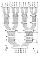
- FIG. 2 shows the detailed diagram of the transcoder device 2 in the case where 127 words of 32 binary elements each have to be added together.
- the transcoder 2 comprises, on the input side, a first stage with eight elementary transcoder circuits respectively referenced 8 to 15.
- These transcoder circuits for example FPLA (programmable logic networks) of the 82S100 type from Signetics with sixteen inputs, being programmed to supply each on its five outputs the value, in pure binary, of the total number of "1" present on all its inputs.
- the inputs of these transcoder circuits are respective ment referenced E 1 to E 127 , the last input of circuit 15 not being used.
- each time two transcoder circuits are grouped and connected, by means of flip-flop registers of type D, 16 to 19, to corresponding inputs of four adder circuits of a second processing stage, respectively referenced 20 to 23.
- Each of these four adder circuits provides the sum of its two input values from two corresponding transcoder circuits on its outputs.
- the outputs of the adder circuits 20 to 23 are also grouped for each time two adders and connected, via two registers 24 and 25, to corresponding inputs of two other adders 26, 27 forming the third processing stage, and finally the outputs of the adders 26 and 27 are connected via two registers 28, 29 to corresponding inputs of an adder 30 forming the last processing stage of the transcoder device and supplying the value on its seven outputs 31 to 37, pure binary, of the total of "1" of the same rank which were present simultaneously on the 127 inputs E to E 127 ,
- the clock signal inputs of all the registers are connected to a terminal 38 which is itself connected to terminal 7.
- the conformation of the transcoder device of FIG. 2 is due to the use of elementary trancoder circuits 8 to 15 with sixteen inputs each, the most efficient currently available, and that, of course, if transcoder circuits were available at 128 inputs, the device in FIG. 2 would be reduced to a single such circuit.
- the pyramidal structure in stages in accordance with the invention can still be used when it is desired to add together a number of words greater than the number of inputs of the available transcoder circuits.
- the outputs of the transcoder circuits and of the adder circuits can be grouped in a non-symmetrical manner, provided that the weights of the different outputs and inputs of the transcoder or adder circuits are respected.
- the different registers of the transcoder device 2 are not absolutely necessary, but it is preferable to use them. to properly synchronize the operation of the different stages of this transcoder device.
- the adder 30 On the second rising edge of the clock signal, the four partial sums supplied by the adders 20 to 23 arrive at the adders 26 and 27, the two partial sums of which reach the last adder 30 at the third rising edge of the clock signal, the adder 30 immediately providing to the input of register 3 the value in pure binary, the total of "1" of weight 2 0 words present in the input registers 1 1 to 1 127.
- Said first edge of the clock signal not only transfers into the adders 20 to 23 the results supplied by the transcoder circuits 8 to 15 for all the binary elements of weight 20 of the words to be added, but also presents the inputs E to E 127 binary elements of weight 2 1 which follow the same treatment as binary elements of weight 2 0 , and so on up to binary elements of weight 2 31
- the fourth rising edge of the clock signal transfers into the adder-divider 4 the first useful content of register 3, that is to say the value of the total of "1s" of weight 20 of the words to be added.
- the adder-divider 4 adds this value to the output value of register 6, which is zero because at the start of the addition of the words there is no reserve, register 6 having been previously reset so as to appropriate, then proceeds to a shift of one step to the right (towards the least significant binary elements) of this value, that is to say that it realizes the division by 2, then it sends in the register 5 the least significant binary element after shift, namely the fraction part nary (2) of the result of the division and sends to register 6 the other shifted bits.
- the adder 4 performs the half-sum of the value of the total of "1" of the binary weight considered and of the value of the total of "1" of carry, sends the fractional part of this half-sum in the register 5 and send the entire part to register 6 of deductions.
- the value of the total of the elements of binary weight 2 1 of the words to be added reaches the adder-divider 4 from the adder 3, and simultaneously, the register 6 sends it the value of the total deductions for binary items of weight 2 0 .
- the adder-divider 4 performs the sum of these two values, then divides it by two, sends the fractional part of the result in register 5 and the whole part in register 6.
Landscapes
- Engineering & Computer Science (AREA)
- General Physics & Mathematics (AREA)
- Physics & Mathematics (AREA)
- Theoretical Computer Science (AREA)
- Mathematical Analysis (AREA)
- Pure & Applied Mathematics (AREA)
- Computational Mathematics (AREA)
- Computing Systems (AREA)
- Mathematical Optimization (AREA)
- General Engineering & Computer Science (AREA)
- Mathematical Physics (AREA)
- Complex Calculations (AREA)
- Compression, Expansion, Code Conversion, And Decoders (AREA)
- Reduction Or Emphasis Of Bandwidth Of Signals (AREA)
Abstract
Les mots à additionner ensemble sont mémorisés dans des registres à décalage (1i à 1p) dont les sorties série sont reliées à des entrées correspondantes d'un transcodeur (2) fournissant la valeur binaire du nombre "1" pour chaque poids binaire des mots à additionner. Cette valeur est envoyée à un additionneur-diviseur (4) qui l'additionne au nombre de "1" de retenue de poids immédiatement inférieur, effectue la division par 2 de cette somme, envoie dans un registre de sortie (5) la partie fractionnaire de la demi-somme et dans un registre de retenue la partie entière. Application: filtres numériques en téléphonie MIC.The words to be added together are stored in shift registers (1i to 1p) whose serial outputs are connected to corresponding inputs of a transcoder (2) providing the binary value of the number "1" for each binary weight of the words to add. This value is sent to an adder-divider (4) which adds it to the number of "1" holding the next lower weight, divides this sum by 2, sends the fractional part to an output register (5) of the half sum and in a deduction register the whole part. Application: digital filters in MIC telephony.
Description
La présente invention se rapporte à un procédé de traitement rapide de mots binaires pour en effectuer l'addition simultanée, et à un dispositif additionneur rapide pour la mise en oeuvre de ce procédé.The present invention relates to a method for rapidly processing binary words to perform simultaneous addition, and to a rapid adder device for implementing this method.
Les additionneurs numériques actuellement utilisés pour additionner plusieurs nombres binaires, ayant chacun un grand nombre d'éléments binaires, comportent une cascade de cellules addition- neuses réalisant chacune deux fonctions booléennes à trois variables, la retenue se propageant de cellule en cellule, ce qui nécessite un temps de calcul relativement long. Pour diminuer le retard dû à la propagation de la retenue, on a recours à des circuits supplémentaires fournissant une retenue anticipée. Cependant, l'encombrement de ces derniers additionneurs devient prohibitif lorsque le format des mots binaires à additionner augmente.The digital adders currently used to add several binary numbers, each having a large number of binary elements, comprise a cascade of adding cells each carrying out two Boolean functions with three variables, the carry propagating from cell to cell, which requires a relatively long computation time. To reduce the delay due to the propagation of the restraint, additional circuits are used which provide early restraint. However, the size of these latter adders becomes prohibitive when the format of the binary words to be added increases.
Dans de nombreuses applications des additionneurs, par exemple dans les filtres numériques, les transformateurs de Fourier, les corrélateurs numériques en temps réel, il est nécessaire d'effectuer un grand nombre d'additions en un temps court, par exemple environ 65 millions d'additions par seconde sur des mots de 16 éléments binaires (bits) dans certains filtres numériques transversaux. Dans de tels cas, même les additionneurs rapides à retenue anticipée ne conviennent plus.In many applications of adders, for example in digital filters, Fourier transformers, digital correlators in real time, it is necessary to carry out a large number of additions in a short time, for example about 65 million additions per second on words of 16 binary elements (bits) in certain transverse digital filters. In such cases, even fast-hold fast adders are no longer suitable.
La présente invention a pour objet un procédé de traitement de mots binaires permettant d'effectuer l'addition simultanée d'un grand nombre de mots composés d'un grand nombre d'éléments binaires en un temps le plus court possible avec les moyens actuellement disponibles, et a également pour objet un dispositif additionneur pour la mise en oeuvre de ce procédé.The subject of the present invention is a method of processing binary words allowing the simultaneous addition of a large number of words composed of a large number of binary elements in the shortest possible time with the means currently available. , and also relates to an adder device for implementing this method.
Le procédé de traitement conforme à la présente invention consiste, à partir de mots mémorisés chacun dans un registre à décalage et extraits à la sortie série de ces registres, à extraire séquentiellement tous les éléments binaires de même poids en commençant par ceux de poids le plus faible et en progressant dans l'ordre vers ceux de poids le plus élevé, à déterminer à chaque fois le nombre de "1" parmi tous les éléments binaires de même poids, à ajouter, pour chaque poids considéré d'éléments binaires, le nombre de "1" de retenue relative aux éléments binaires de poids immédiatement inférieur, à calculer la demi-somme de ces deux nombres, à envoyer un "1" dans un registre à décalage lorsque cette demi-somme n'est pas un nombre entier, et un "0" dans le cas contraire, à mémoriser un ncmbre égal à la partie entière de cette demi-somme, et à extraire ce dernier nombre en tant que nombre de "1" de retenue pour l'utiliser lors du calcul de la demi-somme immédiatement suivante.The processing method in accordance with the present invention consists, starting from words each stored in a shift register and extracted at the serial output of these registers, sequentially extracting all the binary elements of the same weight starting with those of most significant weight weak and progressing in order towards those of highest weight, to be determined at each times the number of "1" among all the binary elements of the same weight, to add, for each considered weight of binary elements, the number of "1" of retention relating to the binary elements of immediately lower weight, to calculate the half sum of these two numbers, to send a "1" in a shift register when this half-sum is not an integer, and a "0" otherwise, to memorize a number equal to the whole part of this half-sum, and extracting the latter number as a number of "1" holdbacks for use when calculating the immediately following half-sum.
Le dispositif de mise en oeuvre du procédé de la présente invention comporte un dispositif transcodeur dont les différentes entrées sont reliées aux sorties série des différents registres à décalage dans lesquels sont mémorisés les mots à additionner ensemble, ce dispositif transcodeur étant réalisé de façon à présenter sur ses sorties la valeur, en binaire pur, du nombre de "1" présents sur ses entrées, les sorties de ce dispositif transcodeur étant reliées par l'intermédiaire d'un registre à bascules bistables à des entrées de poids binaires correspondants d'un circuit additionneur-diviseur binaire parallèle lui-même relié à un registre de mémorisation de la somme des retenues, la sortie de poids le plus faible de ce circuit additionneur-diviseur étant reliée à l'entrée série d'un registre à décalage de sortie.The device for implementing the method of the present invention comprises a transcoder device, the different inputs of which are connected to the serial outputs of the different shift registers in which the words to be added together are stored, this transcoder device being produced so as to present on its outputs the value, in pure binary, of the number of "1" present on its inputs, the outputs of this transcoder device being connected via a flip-flop register to corresponding binary weight inputs of a circuit parallel binary adder-divider itself connected to a storage register for the sum of the holdbacks, the least significant output of this adder-divider circuit being connected to the serial input of an output shift register.
Selon un mode de réalisation particulier du dispositif de l'invention,destiné à l'addition d'un grand nombre de mots, par exemple supérieur à 16, le dispositif transcodeur a une structure pyramidale à plusieurs étages de traitement, l'étage d'entrée, à la base de la pyramide, comportant en parallèle plusieurs circuits transcodeurs élémentaires fournissant chacun sur ses différentes sorties la valeur, en binaire pur, du nombre de "1" pour chaque poids binaire de tous les mots arrivant sur toutes ses entrées, les sorties d'au moins deux circuits transcodeurs différents étant regroupées, à chaque fois, à l'entrée d'un circuit additionneur présentant sur ses sorties la somme des valeurs d'entrée, plusieurs étages de tels circuits additionneurs étant disposés en cascade, chacun de ces étages comportant un nombre de circuits additionneurs inférieur à celui de l'étage précédent, par exemple la moitié, le dernier étage, au sommet de la pyramide, ne comportant qu'un seul circuit combinatoire. De préférence, les différents étages successifs constituant le dispositif transcodeur sont reliés entre eux par l'intermédiaire de registresà bascules bistables, à entrées et sorties parallèles, tous les registres étant reliés à un générateur commun de signaux d'horloge.According to a particular embodiment of the device of the invention, intended for the addition of a large number of words, for example greater than 16, the transcoder device has a pyramid structure with several processing stages, the stage of input, at the base of the pyramid, comprising in parallel several elementary transcoder circuits each supplying on its different outputs the value, in pure binary, of the number of "1" for each binary weight of all the words arriving on all its inputs, the outputs of at least two different transcoder circuits being grouped, each time, at the input of an adder circuit presenting on its outputs the sum of the input values, several stages of such adder circuits being arranged in cascade, each of these stages comprising a number of adding circuits lower than that of the preceding stage, for example half, the last stage, at the top of the pyramid, comprising only one combinatory circuit. Preferably, the different successive stages constituting the transcoder device are interconnected by means of flip-flop registers, with parallel inputs and outputs, all of the registers being connected to a common generator of clock signals.
La présente invention sera mieux comprise à l'aide de la description détaillée d'un mode de réalisation pris comme exemple non limitatif et illustré par le dessin annexé, sur lequel :
- - la figure 1 est un schéma général d'un additionneur rapide conforme à la présente invention, et
- - la figure 2 est le schéma détaillé du dispositif transcodeur de la figure 1.
- FIG. 1 is a general diagram of a fast adder according to the present invention, and
- - Figure 2 is the detailed diagram of the transcoder device of Figure 1.
L'additionneur rapide représenté schématiquement sur la figurel est destiné à l'addition simultanée de 127 mots par exemple, comportant chacun un grand nombre d'éléments binaires, par exemple 32. Toutefois, il est bien entendu que le nombre de mots que l'on peut additionner ensemble peut être différent, et que les mots peuvent contenir un nombre différent d'éléments binaires, les modifications à apporter au dispositif de l'invention étant évidentes pour l'homme de l'art à la lecture de la présence description.The fast adder represented diagrammatically on the figurel is intended for the simultaneous addition of 127 words for example, each comprising a large number of binary elements, for example 32. However, it is understood that the number of words that the it can be added together may be different, and that the words may contain a different number of binary elements, the modifications to be made to the device of the invention being obvious to those skilled in the art on reading the presence description.
L'additionneur de la figure 1 comporte, côté entrée, p registres à décalage, respectivement référencés 1 à 1P, p étant le nombre de mots à additionner ensemble, 127 dans le cas présent, ces registres comportant par exemple chacun 32 cellules si le nombre maximal n d'éléments binaires des mots à additionner est de 32. Les mots à additionner ensemble peuvent être introduits dans ces registres à décalage soit en mode série, soit en mode parallèle selon la conformation des circuits branchés en amont de l'additionneur.The adder of FIG. 1 comprises, on the input side, p shift registers, respectively referenced 1 to 1 P , p being the number of words to be added together, 127 in the present case, these registers for example each comprising 32 cells if the maximum number n of binary elements of the words to be added is 32. The words to be added together can be introduced into these shift registers either in serial mode or in parallel mode depending on the configuration of the circuits connected upstream of the adder.
La sortie série de chaque registre 11 à 1127 est reliée à une entrée correspondante d'un transcodeur 2 décrit plus en détail ci-dessous. Dans le cas de l'addition de 127 mots, le transcodeur 2 comporte sept sorties de poids binaires respectifs 2 à 2 . Les différentes sorties du transcodeur 2 sont reliées, par l'intermédiaire d'un registre 3, à une série d'entrées correspondantes de même poids d'un circuit additionneur-diviseur binaire 4 qui peut par exemple être réalisé de façon connue en soi à l'aide de deux circuits intégrés 74283 de Texas Instruments. Le registre 3 est à entrées et sorties parallèles et se compose par exemple de façon classique de huit cellules à bascule bistable de type D, l'une de ces cellules étant inutilisée.The serial output of each register 1 1 to 1 127 is connected to a corresponding input of a
La sortie de point le plus faible du circuit additionneur-diviseur 4 est reliée à l'entrée série d'un registre à décalage 5 comportant un nombre de cellules suffisant pour contenir tous les éléments binaires du résultat. Pour l'exemple précité de l'addition de 127 mots de 32 éléments binaires chacun, on démontre facilement que le résultat comporte au maximum 39 éléments binaires. Le registre 5 sera alors un registre standard à 40 cellules.The weakest point output of the adder-divider circuit 4 is connected to the serial input of a
Les autres sorties du circuit additionneur-diviseur 4 sont respectivement reliées à une autre série de ses entrées de poids correspondants par l'intermédiaire d'un registre 6 à entrées et sorties parallèles, de même constitution que le registre 3.The other outputs of the adder-divider circuit 4 are respectively connected to another series of its corresponding weight inputs via a register 6 with parallel inputs and outputs, of the same constitution as
On peut disposer du résultat de l'addition soit sur la sortie série S du registre 5, et ce au fur et à mesure des opérations de calcul décrites ci-dessous, soit sur les sorties parallèles S1 à S du registre 5 à la fin des opérations de calcul.We can have the result of the addition either on the serial output S of
La circulation des informations dans les registres à décalage 11 à 1p et 5, ainsi que le transit dans les registres 3 et 6 sont commandés par un signal d'horloge arrivant sur la borne 7 qui est reliée à l'entrée CK de signaux d'horloge de tous ces registres.The circulation of information in the shift registers 1 1 to 1p and 5, as well as the transit in the
On a représenté sur la figure 2 le schéma détaillé du dispositif transcodeur 2 dans le cas où l'on doit additionner ensemble 127 mots de 32 éléments binaires chacun.FIG. 2 shows the detailed diagram of the
Le transcodeur 2 comporte, côté entrée, un premier étage à huit circuits transcodeurs élémentaires respectivement référencés 8 à 15. Ces circuits transcodeurs, par exemple des FPLA (réseaux logiques programmables) de type 82S100 de Signetics à seize entrées, étant programmés pour fournir chacun sur ses cinq sorties la valeur, en binaire pur, du nombre total de "1" présents sur toutes ses entrées. Les entrées de ces circuits transcodeurs sont respectivement référencées E1 à E127, la dernière entrée du circuit 15 n'étant pas utilisée.The
Les sorties de chaque fois deux circuits transcodeurs sont regroupées et reliées, par l'intermédiaire de registres à bascules bistables de type D,16 à 19, à des entrées correspondantes de quatre circuits additionneurs d'un second étage de traitement, respectivement référencés 20 à 23. Chacun de ces quatre circuits additionneurs fournit sur ses sorties la somme de ses deux valeurs d'entrée provenant de deux circuits transcodeurs correspondants. Les sorties des circuits additionneurs 20 à 23 sont également regroupées pour chaque fois deux additionneurs et reliées, par l'intermédiaire de deux registres 24 et 25, à des entrées correspondantes de deux autres additionneurs 26, 27 formant le troisième étage de traitement, et enfin les sorties des additionneurs 26 et 27 sont reliées par l'intermédiaire de deux registres 28, 29 à des entrées correspondantes d'un additionneur 30 formant le dernier étage de traitement du dispositif transcodeur et fournissant sur ses sept sorties 31 à 37 la valeur, en binaire pur, du total des "1" de même rang qui étaient présents simultanément sur les 127 entrées E à E 127,The outputs of each time two transcoder circuits are grouped and connected, by means of flip-flop registers of type D, 16 to 19, to corresponding inputs of four adder circuits of a second processing stage, respectively referenced 20 to 23. Each of these four adder circuits provides the sum of its two input values from two corresponding transcoder circuits on its outputs. The outputs of the adder circuits 20 to 23 are also grouped for each time two adders and connected, via two
Les entrées de signal d'horloge de tous les registres sont reliées à une borne 38 qui est elle-même reliée à la borne 7.The clock signal inputs of all the registers are connected to a terminal 38 which is itself connected to terminal 7.
On remarquera que la conformation du dispositif transcodeur de la figure 2 est due à l'utilisation de circuits trancodeurs élémentaires 8 à 15 à seize entrées chacun, les plus performants actuellement disponibles, et que, bien entendu, si l'on disposait de circuits transcodeurs à 128 entrées, le dispositif de la figure 2 se réduirait à un seul tel circuit. Toutefois, la structure pyramidale en étages conforme à l'invention pourra toujours être utilisée lorsque l'on voudra additionner ensemble un nombre de mots supérieur au nombre des entrées des circuits transcodeurs disponibles. On remarquera également que les sorties des circuits transcodeurs et des circuits additionneurs peuvent être regroupées de façon différente non symétrique, à condition de respecter les poids des différentes sorties et entrées des circuits transcodeurs ou additionneurs.It will be noted that the conformation of the transcoder device of FIG. 2 is due to the use of elementary trancoder circuits 8 to 15 with sixteen inputs each, the most efficient currently available, and that, of course, if transcoder circuits were available at 128 inputs, the device in FIG. 2 would be reduced to a single such circuit. However, the pyramidal structure in stages in accordance with the invention can still be used when it is desired to add together a number of words greater than the number of inputs of the available transcoder circuits. It will also be noted that the outputs of the transcoder circuits and of the adder circuits can be grouped in a non-symmetrical manner, provided that the weights of the different outputs and inputs of the transcoder or adder circuits are respected.
Les différents registres du dispositif transcodeur 2 ne sont pas absolument nécessaires, mais il est préférable de les utiliser pour bien synchroniser le fonctionnement des différents étages de ce dispositif transcodeur.The different registers of the
L'additionneur décrit ci-dessus fonctionne de la façon suivante: les mots à additionner ensemble sont mémorisés dans les registres d'entrée 11 à 1p (p = 127 dans l'exemple précité), l'élément binaire de poids le plus faible (20) de chacun de ces mots étant disponible à l'entrée du dispositif transcodeur 2. On dispose sur les sorties de chacun des circuits 8 à 15 de la valeur en binaire pur du total des "1" de poids 20 présents à l'entrée. Au premier front montant du signal d'horloge arrivant sur la borne 38, ces valeurs sont transférées dans les additionneurs 20 à 23 pour y être additionnées deux à deux. Au deuxième front montant du signal d'horloge, les quatre sommes partielles fournies par les additionneurs 20 à 23 arrivent aux additionneurs 26 et 27 dont les deux sommes partielles parviennent au dernier additionneur 30 au troisième front montant du signal d'horloge, l'additionneur 30 fournissant aussitôt à l'entrée du registre 3 la valeur, en binaire pur, du total des "1" de poids 20 des mots présents dans les registres d'entrée 11 à 1 127.The adder described above operates as follows: the words to be added together are stored in the input registers 1 1 to 1p (p = 127 in the above example), the least significant binary element (2 0 ) of each of these words being available at the input of the
Ledit premier front du signal d'horloge non seulement transfère dans les additionneurs 20 à 23 les résultats fournis par les circuits transcodeurs 8 à 15 pour tous les éléments binaires de poids 20 des mots à additionner, mais présente aux entrées E à E127 les éléments binaires de poids 21 qui suivent le même traitement que les éléments binaires de poids 20, et ainsi de suite jusqu' aux éléments binaires de poids 2 31 Said first edge of the clock signal not only transfers into the adders 20 to 23 the results supplied by the transcoder circuits 8 to 15 for all the binary elements of weight 20 of the words to be added, but also presents the inputs E to E 127 binary elements of
Le quatrième front montant du signal d'horloge transfère dans l'additionneur-diviseur 4 le premier contenu utile du registre 3, c'est-à-dire la valeur du total des "1" de poids 20 des mots à additionner. L'additionneur-diviseur 4 additionne cette valeur à la valeur de sortie du registre 6, qui est nulle car au début de l'addition des mots il n'y a pas de retenue, le registre 6 ayant été préalablement remis à zéro de façon appropriée, puis procède à un décalage d'un pas ver la droite (vers les éléments binaires de poids plus faible) de cette valeur,c'est-à-dire qu'il en réalise la division par 2, puis il envoie dans le registre 5 l'élément binaire de poids le plus faible après décalage, à savoir la partie fractionnaire (2 ) du résultat de la division et envoie dans le registre 6 les autres éléments binaires décalés. Cela veut dire que l'additionneur 4 effectue la demi-somme de la valeur du total des "1" du poids binaire considéré et de la valeur du total des "1" de retenue, envoie la partie fractionnaire de cette demi-somme dans le registre 5 et en envoie la partie entière dans le registre 6 de retenues.The fourth rising edge of the clock signal transfers into the adder-divider 4 the first useful content of
Au cinquième front montant du signal d'horloge, la valeur du total des éléments de poids binaire 21 des mots à additionner parvient à l'additionneur-diviseur 4 depuis l'additionneur 3, et simultanément, le registre 6 lui envoie la valeur du total des retenues relatives aux éléments binaires de poids 20. L'additionneur-diviseur 4 effectue la somme de ces deux valeurs, puis la divise par deux, envoie la partie fractionnaire du résultat dans le registre 5 et la partie entière dans le registre 6. Ce traitement se poursuit ainsi de suite jusqu'au trente-cinquième front montant du signal d'horloge qui commande l'addition de la valeur du total des "1" de poids 231 au total des retenues relatives aux "1" de poids 230, puis la division par deux de cette somme, l'envoi dans le registre 5 de l'élément binaire de poids le plus faible et l'envoi dans le registre 6 du total des retenues. Ensuite, plus aucun "1" ne peut parvenir du registre 3 dans l'additionneur-diviseur 4, si l'on suppose qu'aucun autre mot n'est plus chargé dans les registres d'entrée 11 à 1127. Donc, à partir du trente-sixième front montant du signal d'horloge, seules les retenues circulent entre le registre 6 et l'additionneur-diviseur 4. On peut facilement démontrer que la valeur maximale du total des "1" de retenue parvenant du registre 6 à l'additionneur-diviseur 4 au trente-sixième front montant est de 126. Par conséquent, tous les 1 de retenue seront épuisés au plus tard après le quarante-deuxième front montant du signal d'horloge. Si on prend par exemple un signal d'horloge à 16 MHz, c'est-à-dire de période égale à 62,5 nanosecondes, l'addition des 127 mots de 32 éléments binaires chacun sera terminée en 2,6 µs, environ, ce qui est tout à fait compatible par exemple avec les durées maximales permises de traitement pour les filtres numériques utilisés en téléphonie MIC, et nettement inférieur au temps de traitement des additionneurs classiques de même capacité.On the fifth rising edge of the clock signal, the value of the total of the elements of
De manière générale, on peut facilement démontrer que si on procède à l'addition de p mots comportant chacun n éléments binaires l'addition sera terminée au plus tard en:n + r + s périodes du signal d'horloge, avec : 2r ≤ p < 2 et s = Log2 (![]()
![]()
On va maintenant vérifier à l'aide d'un exemple simplifié d'addition binaire que le fonctionnement de l'additionneur de l'invention est correct. On se limitera à l'addition de quatre mots a, b, c et d de cinq éléments binaires ("bits") chacun, à savoir : 11110, 01010, 01111, 01111, ce qui fait en décimal : 30, 10, 15 et 15 respectivement. On va placer ces quatre mots à la partie médiane d'un tableau dont la partie supérieure est réservée aux retenues et la ligne inférieure au résultat. On fera l'addition de façon connue analogue à celle utilisée pour réaliser par écrit des additions dans le système décimal.

Pour réaliser l'addition, on écrit, l'un en dessous de l'autre les quatre mots a à d, les bits de même poids se trouvant dans la même colonne, et on les additionne mentalement colonne par colonne en commençant par le poids le plus faible et en reportant une retenue dans la colonne de poids supérieur à chaque fois que l'on additionne deux "1". Pour la colonne de poids 20, on trouve deux "1" et il n'y a bien entendu aucune retenue provenant d'une colonne précédente. On écrit donc sur une ligne du résultat un "0" et on reporte une seule retenue dans la colonne de poids 21.To carry out the addition, one writes, one below the other the four words a to d, the bits of the same weight being in the same column, and they are added mentally column by column starting with the weight the lowest and by carrying a carry-over in the higher weight column each time two "1s" are added. For the
Dans la colonne de poids 21, on trouve quatre "1" provenant des quatre mots et un "I" de retenue, ce qui fait au total cinq "1". On doit donc reporter deux "1" de retenue dans la colonne de poids 22 et on inscrit un "1" pour le résultat dans la colonne 21. On procède ainsi de suite pour toutes les autres colonnes, et on trouve comme résultat : 1000110, c'est-à-dire 70 en notation décimale, qui est bien la somme de 30, 10, 15 et 15.In the
En analysant cette façon d'additionner, on remarque que dans chaque colonne l'élément binaire du résultat est un "0" lorsque le nombre de "1" des mots et des retenues est pair et un "1" lorsque ce nombre est impair, et que d'autre part le nombre de "1" de retenue est égal à la moitié du nombre de "1" de la colonne précédente lorsque ce nombre est pair, est à la moitié du nombre immédiatement inférieur lorsque le nombre de "1" est impair, ce qui revient à dire que le nombre de "1" de retenue est égal à la partie entière de la moitié du nombre de "1" de mots et de retenue de la colonne précédente, et que l'élément binaire du résultat est égal à la partie fractionnaire de cette moitié. On peut vérifier facilement que cette règle est valable dans tous les cas. Par conséquent, le procédé de traitement de mots binaires décrit ci-dessus permet d'obtenir effectivement la somme de ces mots, et le dispositif de mise en oeuvre de ce prodécé fonctionne correctement.By analyzing this way of adding, we notice that in each column the binary element of the result is a "0" when the number of "1" of the words and of the retentions is even and a "1" when this number is odd, and that on the other hand the number of "1" withholding is equal to half the number of "1" in the previous column when this number is even, is half the number immediately below when the number of "1" is odd, which means that the number of "1" retainers is equal to the integer part of half the number of "1" words and retainers in the previous column, and that the binary element of the result is equal to the fractional part of this half. We can easily verify that this rule is valid in all cases. Consequently, the process for processing binary words described above makes it possible to effectively obtain the sum of these words, and the device for implementing this product works correctly.
Claims (5)
Applications Claiming Priority (2)
| Application Number | Priority Date | Filing Date | Title |
|---|---|---|---|
| FR7909325A FR2454136B1 (en) | 1979-04-12 | 1979-04-12 | FAST SEQUENTIAL ADDER |
| FR7909325 | 1979-04-12 |
Publications (2)
| Publication Number | Publication Date |
|---|---|
| EP0020185A1 true EP0020185A1 (en) | 1980-12-10 |
| EP0020185B1 EP0020185B1 (en) | 1983-11-23 |
Family
ID=9224273
Family Applications (1)
| Application Number | Title | Priority Date | Filing Date |
|---|---|---|---|
| EP80400354A Expired EP0020185B1 (en) | 1979-04-12 | 1980-03-17 | Method and apparatus for the serial-parallel addition of a great number of words |
Country Status (8)
| Country | Link |
|---|---|
| US (1) | US4336600A (en) |
| EP (1) | EP0020185B1 (en) |
| AU (1) | AU5737180A (en) |
| BR (1) | BR8002202A (en) |
| CA (1) | CA1158774A (en) |
| DE (1) | DE3065651D1 (en) |
| FR (1) | FR2454136B1 (en) |
| GR (1) | GR67742B (en) |
Cited By (4)
| Publication number | Priority date | Publication date | Assignee | Title |
|---|---|---|---|---|
| EP0375125A2 (en) * | 1988-12-23 | 1990-06-27 | Ampex Systems Corporation | High speed digital data correlator having a synchronous pipe lined full adder cell array |
| GB2294138A (en) * | 1994-09-23 | 1996-04-17 | Cambridge Consultants | Data processing circuits and interfaces |
| US5978827A (en) * | 1995-04-11 | 1999-11-02 | Canon Kabushiki Kaisha | Arithmetic processing |
| US6311263B1 (en) | 1994-09-23 | 2001-10-30 | Cambridge Silicon Radio Limited | Data processing circuits and interfaces |
Families Citing this family (6)
| Publication number | Priority date | Publication date | Assignee | Title |
|---|---|---|---|---|
| EP0051079B1 (en) * | 1980-11-03 | 1984-09-26 | Deutsche ITT Industries GmbH | Binary mos ripple carry parallel adder/subtractor and appropriate adding/subtracting stage |
| EP0489952B1 (en) * | 1990-12-11 | 1998-08-19 | Siemens Aktiengesellschaft | Circuit device for digital bit-serial signal processing |
| US5361220A (en) * | 1991-11-29 | 1994-11-01 | Fuji Photo Film Co., Ltd. | Discrete cosine transformation with reduced components |
| EP0992882A3 (en) * | 1998-10-06 | 2003-03-05 | Texas Instruments Inc. | Bit field processor |
| US6760837B1 (en) | 1998-10-06 | 2004-07-06 | Texas Instruments Incorporated | Bit field processor |
| TWI444021B (en) * | 2007-09-17 | 2014-07-01 | Htc Corp | Method for decrypting serial transmission signal |
Citations (1)
| Publication number | Priority date | Publication date | Assignee | Title |
|---|---|---|---|---|
| US3636334A (en) * | 1969-01-02 | 1972-01-18 | Univ California | Parallel adder with distributed control to add a plurality of binary numbers |
Family Cites Families (3)
| Publication number | Priority date | Publication date | Assignee | Title |
|---|---|---|---|---|
| US3711692A (en) * | 1971-03-15 | 1973-01-16 | Goodyear Aerospace Corp | Determination of number of ones in a data field by addition |
| US3723715A (en) * | 1971-08-25 | 1973-03-27 | Ibm | Fast modulo threshold operator binary adder for multi-number additions |
| FR2212952A5 (en) * | 1972-12-29 | 1974-07-26 | Cit Alcatel |
-
1979
- 1979-04-12 FR FR7909325A patent/FR2454136B1/en not_active Expired
-
1980
- 1980-03-17 DE DE8080400354T patent/DE3065651D1/en not_active Expired
- 1980-03-17 EP EP80400354A patent/EP0020185B1/en not_active Expired
- 1980-03-26 GR GR61527A patent/GR67742B/el unknown
- 1980-04-09 BR BR8002202A patent/BR8002202A/en unknown
- 1980-04-10 US US06/138,893 patent/US4336600A/en not_active Expired - Lifetime
- 1980-04-10 CA CA000349541A patent/CA1158774A/en not_active Expired
- 1980-04-11 AU AU57371/80A patent/AU5737180A/en not_active Abandoned
Patent Citations (1)
| Publication number | Priority date | Publication date | Assignee | Title |
|---|---|---|---|---|
| US3636334A (en) * | 1969-01-02 | 1972-01-18 | Univ California | Parallel adder with distributed control to add a plurality of binary numbers |
Non-Patent Citations (1)
| Title |
|---|
| IEEE TRANSACTIONS ON COMPUTERS, Vol. C17, No. 10, Octobre 1968 New York (US) KOUVARAS et al.: "A Digital System of Simultaneous Addition of Several Binary Numbers", pages 992-997. * Figure 1; page 992, colonne de droite, alinea 2 a page 995, colonne de droite, alinea 5 * * |
Cited By (6)
| Publication number | Priority date | Publication date | Assignee | Title |
|---|---|---|---|---|
| EP0375125A2 (en) * | 1988-12-23 | 1990-06-27 | Ampex Systems Corporation | High speed digital data correlator having a synchronous pipe lined full adder cell array |
| EP0375125A3 (en) * | 1988-12-23 | 1992-02-26 | Ampex Systems Corporation | High speed digital data correlator having a synchronous pipe lined full adder cell array |
| GB2294138A (en) * | 1994-09-23 | 1996-04-17 | Cambridge Consultants | Data processing circuits and interfaces |
| US6311263B1 (en) | 1994-09-23 | 2001-10-30 | Cambridge Silicon Radio Limited | Data processing circuits and interfaces |
| US6901503B2 (en) | 1994-09-23 | 2005-05-31 | Cambridge Consultants Ltd. | Data processing circuits and interfaces |
| US5978827A (en) * | 1995-04-11 | 1999-11-02 | Canon Kabushiki Kaisha | Arithmetic processing |
Also Published As
| Publication number | Publication date |
|---|---|
| DE3065651D1 (en) | 1983-12-29 |
| EP0020185B1 (en) | 1983-11-23 |
| GR67742B (en) | 1981-09-16 |
| CA1158774A (en) | 1983-12-13 |
| FR2454136A1 (en) | 1980-11-07 |
| FR2454136B1 (en) | 1985-12-06 |
| US4336600A (en) | 1982-06-22 |
| BR8002202A (en) | 1980-11-25 |
| AU5737180A (en) | 1980-10-16 |
Similar Documents
| Publication | Publication Date | Title |
|---|---|---|
| EP0046708B1 (en) | Digital distributed-arithmetic processing circuit using multiplexers at the input of a memory | |
| EP0198729B1 (en) | Electronic circuit simulation system | |
| EP0309037A1 (en) | Serial pipeline multiplier | |
| CH616252A5 (en) | ||
| EP0020185B1 (en) | Method and apparatus for the serial-parallel addition of a great number of words | |
| FR2853424A1 (en) | ARCHITECTURE OF COMBINED POLYNOMIAL AND NATURAL MULTIPLIERS | |
| FR2871976A1 (en) | LDPC DECODER | |
| EP0262032A1 (en) | Binary adder having a fixed operand, and a parallel/serial multiplier comprising such an adder | |
| FR2656124A1 (en) | PROGRAMMABLE SERIES MULTIPLIER. | |
| EP0183610B1 (en) | Read-write memory and its use in a linear interpolation circuit | |
| EP1071008B1 (en) | Method for performing multiplication with accumulation in a Galois field | |
| FR2773284A1 (en) | Reed-Solomon signal decoding circuit | |
| EP0242258B1 (en) | Device for the execution of an algorithm (leroux-gueguen) for the coding of a signal by linear prediction | |
| EP0215497A1 (en) | Autocorrelation device | |
| EP0175623A1 (en) | Device for the real-time processing of a digital signal by convolution | |
| FR2731854A1 (en) | DIGITAL FILTERING DEVICE | |
| EP0353826B1 (en) | Statistical-coding device producing code words having a variable number of binary elements | |
| CA2359198C (en) | Arithmetic unit for carrying out a cryptographic protocol | |
| EP0169089B1 (en) | Elementary data processing device | |
| EP0046105B1 (en) | Fast digital operator device | |
| FR2647988A1 (en) | DEVICE FOR DELAYING A PROGRAMMABLE DIGITAL SIGNAL AND APPLICATION TO AN ERROR-CORRECTING DEVICE | |
| EP0125156B1 (en) | Cascaded multiplier using a set of elementary operators | |
| FR2491652A1 (en) | DEVICE FOR PERFORMING A MATHEMATICAL OPERATION AND DIFFERENT APPLICATIONS THEREOF | |
| FR2627605A1 (en) | DEVICE FOR CALCULATING PARITY BITS OF A SUM OF TWO NUMBERS | |
| FR2552904A1 (en) | Calculation processor |
Legal Events
| Date | Code | Title | Description |
|---|---|---|---|
| PUAI | Public reference made under article 153(3) epc to a published international application that has entered the european phase |
Free format text: ORIGINAL CODE: 0009012 |
|
| AK | Designated contracting states |
Designated state(s): BE DE GB IT SE |
|
| 17P | Request for examination filed |
Effective date: 19810115 |
|
| ITF | It: translation for a ep patent filed |
Owner name: JACOBACCI & PERANI S.P.A. |
|
| GRAA | (expected) grant |
Free format text: ORIGINAL CODE: 0009210 |
|
| AK | Designated contracting states |
Designated state(s): BE DE GB IT SE |
|
| REF | Corresponds to: |
Ref document number: 3065651 Country of ref document: DE Date of ref document: 19831229 |
|
| PGFP | Annual fee paid to national office [announced via postgrant information from national office to epo] |
Ref country code: DE Payment date: 19840209 Year of fee payment: 5 |
|
| PGFP | Annual fee paid to national office [announced via postgrant information from national office to epo] |
Ref country code: BE Payment date: 19840331 Year of fee payment: 5 |
|
| PLBE | No opposition filed within time limit |
Free format text: ORIGINAL CODE: 0009261 |
|
| STAA | Information on the status of an ep patent application or granted ep patent |
Free format text: STATUS: NO OPPOSITION FILED WITHIN TIME LIMIT |
|
| 26N | No opposition filed | ||
| PGFP | Annual fee paid to national office [announced via postgrant information from national office to epo] |
Ref country code: SE Payment date: 19841231 Year of fee payment: 6 |
|
| PG25 | Lapsed in a contracting state [announced via postgrant information from national office to epo] |
Ref country code: SE Effective date: 19870318 |
|
| BERE | Be: lapsed |
Owner name: THOMSON-CSF TELEPHONE Effective date: 19870331 |
|
| GBPC | Gb: european patent ceased through non-payment of renewal fee | ||
| PG25 | Lapsed in a contracting state [announced via postgrant information from national office to epo] |
Ref country code: DE Effective date: 19871201 |
|
| PG25 | Lapsed in a contracting state [announced via postgrant information from national office to epo] |
Ref country code: GB Effective date: 19881118 |
|
| PG25 | Lapsed in a contracting state [announced via postgrant information from national office to epo] |
Ref country code: BE Effective date: 19890331 |
|
| EUG | Se: european patent has lapsed |
Ref document number: 80400354.9 Effective date: 19880215 |