EP0104963B1 - Method of reducing the data rate of data successively transmitted between a transmitter and a receiver, and a system for carrying out the method - Google Patents
Method of reducing the data rate of data successively transmitted between a transmitter and a receiver, and a system for carrying out the method Download PDFInfo
- Publication number
- EP0104963B1 EP0104963B1 EP83401631A EP83401631A EP0104963B1 EP 0104963 B1 EP0104963 B1 EP 0104963B1 EP 83401631 A EP83401631 A EP 83401631A EP 83401631 A EP83401631 A EP 83401631A EP 0104963 B1 EP0104963 B1 EP 0104963B1
- Authority
- EP
- European Patent Office
- Prior art keywords
- point
- costs
- encoding
- data
- cost
- Prior art date
- Legal status (The legal status is an assumption and is not a legal conclusion. Google has not performed a legal analysis and makes no representation as to the accuracy of the status listed.)
- Expired
Links
Images


Classifications
-
- H—ELECTRICITY
- H04—ELECTRIC COMMUNICATION TECHNIQUE
- H04N—PICTORIAL COMMUNICATION, e.g. TELEVISION
- H04N19/00—Methods or arrangements for coding, decoding, compressing or decompressing digital video signals
- H04N19/10—Methods or arrangements for coding, decoding, compressing or decompressing digital video signals using adaptive coding
- H04N19/102—Methods or arrangements for coding, decoding, compressing or decompressing digital video signals using adaptive coding characterised by the element, parameter or selection affected or controlled by the adaptive coding
- H04N19/124—Quantisation
-
- H—ELECTRICITY
- H04—ELECTRIC COMMUNICATION TECHNIQUE
- H04N—PICTORIAL COMMUNICATION, e.g. TELEVISION
- H04N19/00—Methods or arrangements for coding, decoding, compressing or decompressing digital video signals
- H04N19/50—Methods or arrangements for coding, decoding, compressing or decompressing digital video signals using predictive coding
Definitions
- the invention relates to a method and a system for compressing the data rate transmitted between a transmitter and a television receiver.
- the luminance and color difference signals are digitized to eight binary elements per point, with a structure and a sampling frequency which depend on the problem treated.
- This information is generally transmitted in real time and their gross speed is very high, higher than 140 megabits / second, in principle, which requires reducing their speed in order to be able to use existing transmission media.
- Different methods and devices for rate reduction are known, among these, the methods of coding by modulation of differential coded pulses of television signals are particularly advantageous by their simplicity of implementation, and this all the more so since the data transmitted are constituted by binary code words of fixed length, because the problems of management of the buffer memories necessary for the adaptation of the variable bit rate of the transmitter to the fixed bit rate of the channel connecting the transmitter to the receiver are eliminated, and moreover, the use of intra-image coding makes it possible to avoid the systematic use of image memories.
- the known differential coding methods consist in coding the difference between the value of a sample of the signal and an estimate, or prediction, calculated from the values of the previous samples already coded, this difference being quantified by a quantizer with n quantization levels. .
- Each level i is associated with a code C which is transmitted on the transmission line or channel.
- the code received is transformed into its actual value which is then added to a prediction value calculated by the receiver to reconstruct the signal.
- a feedback loop makes it possible to make a prediction at the transmitter level identical to that which is produced at the receiver.
- one solution consists in switching the quantizers to two different quantization characteristics as a function of the local aspect of the point of the image to be transmitted. For example, for points located in uniform areas of the image, the coding will be carried out using a quantizer with tightened reconstruction levels in the vicinity of the zero prediction error, and for points located in the contours or texture of the image, a quantizer with high reconstruction levels will be used.
- Known switching methods on different quantization characteristics, can be classified into two groups according to whether the switching instant is or is not transmitted.
- the characteristic is obtained in an identical manner to the transmitter and to the receiver from tests which are carried out on points of the image already known to the receiver which constitute the causal neighborhood of the point to be coded.
- the bit rate of each image line is constant since the only information to be transmitted is the value of the quantized prediction error.
- the object of the invention is to overcome the aforementioned drawbacks.
- the subject of the invention is a method for compressing the bit rate of data successively transmitted between a transmitter and a television receiver, the data being both representative of the luminance or chrominance values of each point of a television image and being encoded at the transmitter by a differential coding device of the type comprising at least one predictor, a quantifier, a device for reconstructing the transmitted data and a code allocator and decoded at the receiver by a differential decoder comprising at least one transformer codes, a predictor and a device for reconstructing the transmitted data, the method consisting in determining before transmission the codes to be transmitted as a function of at least two different characteristics 0 1 and Q 2 of quantization and / or prediction P 1 and P 2, both with very tight quantization and / or prediction levels in the uniform areas of the image and to transmit the indication of ch characteristic change at the receiver when the coding of the data is obtained using a characteristic different from that which was used for the previously transmitted data, characterized in that it consists in transmitting the indication of change
- the method according to the invention consists, in determining the code of the data to be transmitted, in establishing the coding costs and the corresponding codes of the data of each point to be transmitted for each of the quantification and / or prediction characteristics used , each cost being obtained by a measurement of the exceeding of the coding error of each point above a visibility threshold for which the error becomes apparent on the image received, to define a first series of costs to code the data for each point using a first characteristic and a second cost sequence to code the data for each point using a second characteristic, each cost of a sequence being obtained from the costs obtained corresponding to the coding of the previous point by determining the minimum of the costs calculated according to either the previous cost of the same suite or the previous cost of the other suite, to be identified in each suite, when ide of a change code, each minimum cost which is obtained from the cost of coding the previous point of the other sequence and to arrange the codes to be transmitted corresponding to the calculated costs of one or the other sequence by determining a coding path alternating on one or the
- a subject of the invention is also a system for compressing the data rate transmitted between a transmitter and a receiver using the above-mentioned method.
- the known differential coding-decoding system represented in FIG. 1 is constituted, on the transmitter side, by a differential coding device 1, represented inside a dotted rectangle, and on the receiver side, by a decoding device differential 2, also shown inside a dotted rectangle.
- the output of the coding device 1 is connected to the input of the decoding device 2 via a transmission channel 3.
- the differential coding device 1 comprises: a predictor 4, a quantizer 5, a reconstruction device of the transmitted data 6, as well as a code allocator 7.
- the data X to be transmitted is applied to the input of a subtractor 8, the other input of which is connected to the output of the predictor 4.
- the predictor 4 delivers a prediction value P.
- the data to be coded X reduced by the value of the prediction P is applied to the input of the quantizer 5, by the output of the subtractor 8, to be quantified according to n levels.
- a code allocator 7 associates a code C which is transmitted on the line or channel 3.
- the quantization level dq delivered by the quantifier 5 and which corresponds to the difference or prediction error X-P is applied to the input of the device for reconstructing the transmitted data 6, generally consisting of an adder, the other input of which is connected to the output of the predictor 4.
- the reconstructed data X re transmitted to the output of the reconstruction device of the transmitted data 6, is applied to the input of the predictor 4.
- the code C is received by the decoding device 2 which is constituted by a code transformer 9, a predictor 10 and a device for reconstructing the received data 11.
- the code transformer 9 reconstructs the quantization levels dq in order to apply them to a first input to the device for reconstructing the received data 11.
- the device for reconstructing the received data generally consisting of an adder, receives on another input the value of the prediction P 'calculated by the predictor 10 and delivers on its output the value X rr of the reconstructed datum received.
- the quantization operation carried out by the quantizer 5 makes it possible to associate with all the difference values X - P between two thresholds S i and S I + 1 a single value of code C i .
- This operation carried out with the help of the code allocator 7, allows differential coding to achieve the bit rate reduction.
- the reconstructed values respectively X re and X rr at the transmitter and at the receiver are identical.
- the method and the system according to the invention implement a differential coding system conforming to that which is described in FIG. 1 with the difference, however, that two characteristics of quantization and / or prediction, instead of one, are used.
- the transmitter as to the receiver and that it further comprises, a device for transmitting an indication of change in characteristic in place of the corresponding point which must be transmitted when the point is in an image area requiring this change and a device, at the receiver, for reconstructing the point not transmitted as a function of the samples already known to the receiver.
- the method according to the invention consists in minimizing a function taking into account coding errors, of a determined number of points, above a threshold defined by a visibility function of these errors. .
- the taking into account function chosen may be, depending on the application, either the simple sum of the visibility of coding errors or the sum of squares or cubes or nth powers of the visibility of coding errors.
- the coding error corresponds either to the prediction error X - P minus its quantized value Q (X - P), Q representing the quantization characteristic used, or to the difference between the data X and the reconstructed value of the previous data.
- the visibility function determines the threshold above which the coding error becomes apparent in the received image, and the points considered in this calculation mode are, for simplification of embodiment, those constituting a television image line .
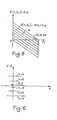
- a graph of a visibility function is represented in FIG. 2.
- the abscissa is plotted the difference (X - X) representing the difference between the value X of the datum of the point to be coded and a reconstructed value X of the point obtained at from the points adjacent to the point to be coded.
- Each coding error is associated with a cost Ci which is zero for any error below the threshold defined by the visibility function and which is, for example, proportional to the value of the error exceeding the threshold.
- a dynamic programming method will be used which, at each image point, will propagate two paths each assigned a cost defined from a visibility function. The illustration of this method is represented in FIGS. 3 and 4. Since two quantization characteristics Q 1 and Q 2 can be used to code each picture point, each picture point can be represented by two different coding characteristic states resulting from the use of one or the other of the two quantification characteristics.
- each state will be characterized by a cost of coding Ci or C 2 .
- the states of points Ni and Ni + 1 are represented affected by the costs C 1 (i) and C 1 (i + 1) for state 1, and C 2 (i) and C 2 (i + 1) for state 2.
- C 11 represents the cost of moving from point Ni to point Ni + 1 using the quantization characteristic Q 1
- C 22 represents the cost of moving from point Ni to point Ni + i using the characteristic of quantization Q 2
- C 21 represents the cost to pass from the quantification characteristic Q 2 used for the calculation at the point Ni, to the quantification characteristic Q 1 used for the calculation at the point Ni +
- C 12 represents the cost for to pass from the use of the quantification characteristic at point Ni, to the use of the quantification characteristic Q 2 at point Ni + 1.
- the coding of point Ni + 1 is determined according to the path which has the lowest cost. This coding can be carried out by using the two quantization characteristics shown in FIGS. 5 and 6.
- FIG. 5 represents a quantization characteristic specially used for coding the points located in contour or highly textured areas of the image.
- seven quantization levels can be used.
- a value of K close to 0.45 may be chosen.
- FIG. 6 represents the quantization characteristic used to code points of the image located in uniform areas of the image, it is a linear characteristic with 7 levels having levels tightened in the vicinity of the error of null prediction.
- the method of calculating the codes to be sent and the reconstructed values is now described using the diagram shown in Figure 4. From the costs C 1 (i-1) and C 2 (i-1) known for the point Ni - 1 the method calculates the costs C 1 (i) and C 2 (i) for the point Ni using the method of minimization of a function for taking account of coding errors previously described. For this, it has the data X of the current point of the television signal, the value of the data of the previous point reconstructed XR i-1 and the data reconstructed of certain points of the previous line. The precise points to use depend on the chosen prediction and reconstruction functions.
- a point Ni to be coded requires a calculation of two reconstructed values and two codes, a first reconstructed value XR 1 (i) and a first COD 1 (i) code to place the point Neither in state 1, a second reconstructed value XR 2 (i) and a second COD code 2 (i) to place the point Ni in state 2.
- These values are stored in memory in the order of processing of the points on each image line and the propagation of costs, as shown in FIG. 3, continues until the end of each line.
- the minimum value of the costs Ci or C 2 initializes the search for a coding path for which the cost of the coding error is minimal.
- the method consists in choosing one from the two following possibilities of codes and reconstructed values (XR1 (i) , COD 1 (i) ) or (XR 2 (i) , COD 2 (i) ) to give the COD value i of the code to be transmitted and the reconstructed value XR (i) .
- the choice between these values is controlled by the code values read in the manner shown in FIG. 4.
- the example shown in FIG. 4 is constituted by a line comprising seven points numbered from Ni to N 7 , the values a and b i represent the codes stored in two code memories, MCOD 1 22 and MCOD 2 24 below represented in FIG. 7.
- the letter C denotes the change code which is memorized in one of the two memories MCOD 1 or MCOD 2 when at the point Ni considered, the method of minimizing errors and calculating minimum cost for this point has shown the need to change the quantification characteristic.
- the cost propagation method passes from point Ni in state 1 to point N 2 in state 2.
- a code denoted C is stored in memory MCOD 2 instead of the corresponding code of point N 2 .
- two paths are possible, either coming from state 2 of point N 2 , at state 1 from point N 3 , or coming from state 2 from point N 2 and remaining in state 2 at point N 3 .
- a code a 7 is stored in the memory MCOD 1 and a code b 7 is stored in the memory MCOD 2 . Also, at point N 7 , the cost propagation method reveals a coding error assigned with a cost Ci for state 1 of point N 7 and a coding error assigned with a cost C 2 for state 2. If we always assume in the example shown in FIG.
- the method for searching for the optimal coding path will consist in reading the code located in one or other of the memories MCOD 1 or MCOD 2 starting with the memories of codes representing the points in state 1, that is to say by the memory MCOD 1 and to change of memory when in the succession of codes read a change code C is encountered.
- the dotted line in FIG. 4 represents the succession of codes which will be read according to this principle.
- the reading of the memory MCOD 1 will be carried out, firstly, from point N 7 to point N 5 and the codes a 7 , a s and C will be read, then at the indication of change C of point N 5 , the reading of the memory code 1 will be interrupted and will be followed by the reading in the memory MCOD 2 of point N 4 to point N 2 where the codes b 4 , b 3 and C will be successively read. Arrived at point N 2 where a change code is read, the reading of the memory MCOD 2 will be interrupted, to be followed by the reading again of the memory MCOD 1 to read the code of point Ni.
- the code train which will be sent will be defined by the following codes: a, c, b 3 , b 4 , ca s , a 7 .
- the choice of the reconstructed values XR 1 and XR 2 at the transmitter is made using the same switching or change code C.
- the device represented in FIG. 7 comprises: a device 12 for propagating costs Ci and C 2 , as well as 'A device 13 for calculating the reconstructed codes and values.
- the device 12 is constituted by two circuits 14, 15 for propagating costs for all the points of a line of the image, when, the calculation of the coding errors is carried out respectively using the first and the second quantization characteristic, Q 1 and O 2 , placing the points of the image to be coded respectively in states 1 and 2 defined above.
- a cost propagation circuit 14 calculates the overall cost C 1 (i) to arrive in state 1 at point Ni, the reconstructed value XR 1 (i) at point Ni as well as the COD code 1 (i) obtained corresponding to overall cost C 1 (i) .
- the overall cost C 1 (i) obtained on an output of the cost propagation circuit 14 is stored by a storage circuit 16.
- the reconstructed value XR 1 (i) obtained on an output of the cost propagation circuit 14 is stored inside a storage circuit 17.
- the cost propagation circuit 15 calculates, the overall cost C 2 (i) necessary to place the point Ni in state 2, the reconstructed value XR 2 (i) corresponding obtained using the quantification characteristic Q 2 and the COD 2 code corresponding to the overall cost C 2 (i) obtained.
- the overall cost C 2 (i) provided by a corresponding output of the cost propagation circuit 15 is stored inside a storage circuit 18.
- the reconstructed value XR 2 (i) is obtained on an output of the propagation circuit 15 and is stored inside a storage circuit 19.
- the calculation of the global costs C 1 (i) and C 2 (i) , of the reconstructed values XR 1 (i) and XR 2 (i) , corresponding codes COD 1 and COD 2 are carried out as a function of the current datum X (i) of the point to be coded, of the overall costs C 1 (i-1) C 2 (i-1) obtained in the calculations carried out on the previous point Ni - 1 and stored respectively in the storage circuits 16 and 18, reconstructed values XR 1 (i-1) and XR 2 (i-1) of the data corresponding to the previous point Ni - 1 and stored in the circuits memorization 17 and 19, as well as according to the reconstructed values LP of the preceding line memorized in a memorization circuit 20.
- the device 13 for calculating the reconstructed codes and values consists of a set 21, 22, 23, 24 of stack registers of the FIFO type, abbreviation of the English term “First in-First out”, of a multiplexer 25, a storage circuit 26 for the reconstructed values for all the points of a line, a storage circuit 27 for the codes to be transmitted as well as a control circuit 28 for the inputs of the multiplexer 25.
- the control circuit 28 comprises an initialization circuit 29 for the state of the multiplexer at the end of the image line, as well as a circuit 30 which allows the state of the multiplexer to be changed each time a change code is encountered, in the path of the optimal coding path defined above, starting from the optimum state for the last point of the line.
- the initialization circuit 29 consists of a circuit 31 for calculating the minimum overall cost provided respectively by the cost propagation circuits 14 and 15 as well as a circuit 32 for storing the minimum overall cost obtained at the end of 'an image line.
- the state change circuit 30 of the multiplexer 25 is constituted by a decoder 33 of the change code C, connected by its output to the input of a rocker 34 which changes state each time a change code C is decoded by the encoder 33.
- the outputs of the storage circuit 32 and of the rocker 34 are respectively connected to the control inputs Ci and C 2 of the multiplexer 25.
- the multiplexer 25 connects the output of the battery memory 21 or the output of the battery memory 23 to the input of the device for memorization of the reconstructed values 26, it also connects as a function of these states the output of the battery register 22 or the output of the battery register 24 to the input of the device for memorizing the codes to be transmitted 27.
- the priority for reading the battery memories 21 to 24 will be given to the memories 21 and 22 which contain stacked respectively the reconstructed values XR, and the COD codes, of all the points placed in state 1 of the line obtained by using the first quantization characteristic Q i . These successively read values will be transferred successively and respectively to the storage circuits for the reconstructed values 26 and to the storage circuit 27 for the codes to be transmitted.
- the rocker 34 changes the state of the multiplexer 25 and switches the inputs of the storage circuits 26 and 27 to the outputs of the registers of stack 23 and 24 which respectively contain the reconstructed values and the corresponding codes, points placed in state 2 calculated using the quantization characteristic Q 2 .
- the rocker 34 changes state each time a change code is encountered in reading the battery registers 22 or 24, it can be seen that the multiplexer 25 switches the inputs 26 and 27 alternately on one of the outputs of the registers 21, 22 or 23, 24 each time a change code is encountered.
- the initialization of the multiplexer 25 may take place from the second state of the last point of a line, in the case where the initialization circuit 29 finds at the end of the line that the cost of coding the last point, provided by the cost propagation circuit 15, is less than that provided by the cost propagation circuit 14. In this case, the reading of the codes to be transmitted and the reconstructed values would begin with the reading of the battery memories 23 and 24.
- the cost propagation circuit 14 is shown in FIG. 8.
- This circuit comprises a circuit 36 for calculating a prediction value P 1 using a first prediction characteristic connected by a first input to the output of the circuit 20 for memorizing the reconstructed values of the previous line and on its second input at the output of the memorizing circuit 17 of the reconstructed value XR (i-1) from the previous point.
- the circuit 36 is also connected by its output to a first input of a calculation circuit 37, of coding cost C 11 , when the first quantization characteristic Q 1 is used.
- the calculation circuit 37 is connected to a first input of an adder 38, for transmitting the value of the cost C 11 calculated to the adder 38.
- a second input of the adder 38 is connected to the output of the storage circuit 16 which contains the coding cost C 1 (i-1) of the previous point when the first quantization characteristic is used.
- the adder 38 adds the costs C 11 and C (i-1) and transmits the result to a first input of a circuit 39 for calculating the overall cost C 1 (i) .
- the cost propagation circuit 14 also includes a circuit 40 for calculating the reconstructed value (R,), connected by a first input to the output of the circuit 20 for memorizing the reconstructed values of the previous line and by its second input to the output of the storage circuit 19 of the reconstructed value XR 2 (i-1) from the previous point, to reach state 2 of the point Ni.
- the circuit 40 is also connected by its output to a first input of a circuit 41 for calculating the coding cost C 21 .
- the calculation circuit 40 is connected to a first input of an adder 42 to transmit the value of the cost C 21 calculated to the adder 42.
- a second input of the adder 42 is connected to the output of the storage circuit 18 which contains the coding cost C 2 (i-1) of the previous point when the second quantization characteristic Q 2 is used.
- the adder 42 operates the addition of costs C 21 and C 2 (i-1) and transmits the result to a second input of the circuit 39 for calculating overall costs C 1 (i) .
- the calculation circuits 37 and 41 also respectively calculate the codes COD11 and COD21 as well as the reconstructed values XR 11 and XR 21 corresponding to the costs C 11 and C 2 , calculated previously.
- a multiplexer 43 controlled by the output of the circuit 39 for calculating the overall cost, connects the outputs of the calculation circuit 37 providing the code value COD "and the reconstructed value XR" or connects the outputs of the calculation circuit 41 providing the value of code COD 2 , and the reconstructed value XR 21 , at the respective inputs of the battery memories 22 and 21 of FIG. 7.
- the multiplexer 43 is controlled to transmit the COD code 11 and the reconstructed value calculated by the circuit 37 to the input of the battery memories 21 and 22. Otherwise, when the cost calculated by the adder 42 is less than the cost calculated by the adder 38, only the code COD 2 , and the reconstructed value XR 21 , calculated by the calculation device 41 are transmitted to the inputs of the battery memories 21 and 22.
- the cost propagation circuit 15 represented in FIG. 9 is identical to the circuit 14 represented in FIG. 8, with the input-output connections close, of circuit 15, with the other elements represented in FIG. 7. This is why on Figure 9, the same elements as those of Figure 8 are shown with references increased by ten. Consequently, the connections between the elements 46 to 53 of FIG. 9 need not be described in more detail. However, it will be recalled that circuit 15, shown in FIG. 9, propagates the costs making it possible to code the points using the second quantization characteristic Q 2 , this circuit performing the function
- the cost C 22 is calculated by the calculation circuit 47 as a function of the prediction value P 2 supplied by the predictor 46 using a second prediction characteristic and as a function of the incoming datum of the current point X using the second quantization characteristic Q 2 .
- Circuit 47 also provides the code COD22 and the reconstructed value XR 22 .
- the calculation circuit 51 calculates the cost value C 12 attached to the use of a reconstruction function which is itself a function of the value of the incoming datum X i of the current point and of a reconstructed value R 2 developed by the reconstruction circuit 50.
- the calculation circuit 51 also calculates the code value COD 12 and the reconstructed value XR 22 which correspond to the conditions for calculating the cost C 12 .
- the adder 48 adds the cost values C 22 and C 2 (i-1) and the adder 52 adds the costs C 12 and C 1 (i-1) .
- the minimum of the overall costs obtained by the circuits 48 and 52 is calculated by the calculation circuit 49 which controls the multiplexer 53, in order to select, as a function of the result obtained, a code value and a reconstructed value, on the outputs of the circuit of calculation 47 or on the outputs of the calculation circuit 51.
- the code value COD 2 and the reconstructed value XR 2 selected by the multiplexer 53 are transmitted to the inputs of the battery registers 23 and 24 of FIG. 7.
- the predictor 46 has a first input connected to the output of the storage circuit for the reconstructed values of the previous line 20 and a second input connected to the output of the storage circuit 19 of the previous point.
- the reconstruction circuit 50 has its first input connected to the output of the circuit for memorizing the reconstructed values 20 and its second input connected to the output of the memory circuit 17 for the reconstructed value of the previous point.
- FIG. 10 An embodiment of the circuit 37 for calculating the cost C 11 of coding, to go from coding the point Ni -1 to coding the point Ni using the first quantization characteristic 0 1 , is shown in FIG. 10.
- This circuit includes a subtractor 54, a quantifier 55, a coding error calculation device 56, a device 57 for developing the code C 11 as a function of the coding error delivered by the device 56, of the point data current X i , of the reconstructed value of the previous point XR 1 (i-1) and of the reconstructed values of the points of the previous line LP.
- the calculation device also includes a device 58 for calculating the reconstructed value XR 11 .
- the subtractor 54 receives on a first input the value X i of the data representing the current point Ni and on a second input the value P 1 of the prediction calculated by the predictor 36.
- the subtractor 54 delivers on its output a prediction error X i - P 1 at the input of the quantizer 55 for calculating the COD code 11 , the quantization characteristic of which is that which corresponds to the graph shown in FIG. 5.
- the prediction error X i -P 1 is also transmitted to a first input of the coding error calculating device 56 which receives on its second input the quantized prediction error provided by the quantizer 55.
- the coding error calculating device can be performed using a simple subtractor.
- the coding error calculated by the coding error calculating device 56 is transmitted to the address inputs of a programmable read only memory 57 also addressed as a function of the value of the data item X i of the point Ni, of the reconstructed values of the neighboring points found in the register 17, of the reconstructed value XR 1 (i-1) of the previous point or in the storage circuits 20 for the reconstructed values of the points of the previous line.
- the programmable read-only memory 57 contains in memory the cost values C 11 corresponding to the coding errors greater than the visibility threshold defined by a visibility function of the type of that represented in FIG. 2.
- a certain cost C 11 is output from the memory 57 and this cost C 11 can be zero if the coding error is less than the corresponding visibility threshold.
- the device for calculating the reconstructed value 58 is in the example of. FIG. 10 produced using a simple adder which adds the value of the prediction P 1 delivered by the predictor 36 to the quantized prediction error Q (X-P 1 ) delivered by the quantizer 55 to form the reconstructed value XR 11 .
- FIG. 11 An exemplary embodiment of the cost calculation circuit C 22 is shown in FIG. 11. As this circuit is identical to the circuit of FIG. 10, the elements of FIG. 11 which are homologous to the elements of FIG. 10, are represented with references increased by 10. Similarly to FIG. 10, the programmable memory 67 provides a cost C 22 which represents the difference between a coding error calculated by the circuit 66 and a visibility threshold defined by a visibility function of the type of that represented in FIG. 2, as a function of the difference existing between the datum X i of the current point and of the reconstructed values of the points neighboring the current point such as, in particular, the reconstructed value XR 2 (i-1) of the previous point.
- a cost C 22 which represents the difference between a coding error calculated by the circuit 66 and a visibility threshold defined by a visibility function of the type of that represented in FIG. 2, as a function of the difference existing between the datum X i of the current point and of the reconstructed values of the points neighboring the current point such as,
- the coding error corresponds to the difference between the prediction error X i - P 2 provided by the subtractor 64 and the quantized prediction error Q (X i - P 2 ) provided by the quantizer 65 using the second quantization characteristic Q 2 to calculate the COD code 22 .
- the quantization characteristic Q z conforms to that represented in FIG. 6.
- the quantizer 65 also delivers on its output the corresponding code COD 22 .
- the circuit for calculating the cost C 21 for placing the point Ni + 1 in state 1 coming from state 2 of the point Ni is shown in FIG. 12.
- This circuit comprises a subtractor 69 receiving on a first input the data X i to code from the current point Ni and on its second input the reconstructed value R 1 of the previous point as a function of the neighboring points.
- Subtractor 69 is connected by its output to an input addressing a programmable read only memory 71 which contains a function for visibility of the coding error, the output of which provides a coding cost value C 21 .
- the memory 72 contains the COD code 21 which corresponds to the change of quantifier required by this operation, this COD code 21 could, for example, have the value binary value 111.
- the device represented in FIG. 13 represents the details of the embodiment of the calculation device 51 for coding the cost C 12 of FIG. 9.
- This device contains elements similar to those already described in FIG. 12, and therefore bear the references of the similar elements of FIG. 12 increased by 10.
- the subtractor 79 calculates the coding error EC 12 corresponding to the difference between the current datum X of the current point and the reconstructed value R 2 of the neighboring points provided by the reconstructor 50 of FIG. 9.
- the code EC 12 is transmitted on an address line of the programmable read-only memory 81 which contains a function of visibility of the coding error, similar to that represented in FIG.
- the memory 82 contains the change code COD 12 which, as in the case of FIG. 12, corresponds for example to the binary value 111.
- the reconstructed value XR 12 is taken directly from the input of subtractor 79 receiving the reconstructed value R 2 .
- the embodiment of the reception device is shown in FIG. 14.
- the reception device comprises a control member 83, a device for memorizing the reconstructed values of the previous line 84, a device for memorizing 85 the reconstructed value XR ( i-1) from the previous point, a predictor 86, a multiplexer 87 and an adder 88.
- the controller 83 is constituted by a rocker 89 for changing the state of the prediction characteristic, a register for storing codes 90 and a code counter 91.
- the input j of the rocker 89 is connected to the output of an OR gate 92 with two inputs, the first input being connected to the transmission channel 3 via an AND gate with two inputs 93.
- the second input of the OR gate 92 is connected to the output of an AND gate 94 with three inputs which are respectively connected to the outputs of the register for memorizing the codes received 90.
- the first bit, received on the transmission channel 3 initiali the count of the code counter 91 is counted and positions the rocker 89 in the logic 1 state if the first bit received has the logic value 1, or leaves the rocker 89 in the logic state 0 when the first bit received has the value 0
- the rocker 89 then changes state each time a code change is signaled by the value of the change code c equal 111 coming from the transmission channel.
- the change code C is decoded by the AND gate 94 which, at its output, presents a logic state 1 when the change code is stored inside the code register 90.
- the predictor 86 calculates the prediction values P 1 and P 2 and two reconstructed data values R 1 and R 2 . These values are calculated identically to those obtained by the predictor of the transmitter, using the values of the data reconstructed on the previous line found in the register 84 and the reconstructed value of the previous point found in the register 85.
- the multiplexer 87 controlled by the parts Q and Q of the rocker 89, selects one of the values P 1 , P z , R 1 or R 2 to apply it to a first input of the adder 88 whose other input is connected at the output of the code register 90 which contains the quantized prediction error dq transmitted on the transmission channel 3. The corresponding reconstructed value is transmitted at the output of the adder 88.
- a first solution could consist in using an image memory, to memorize the first and the second frame of the image, the emission of the codes of line J of the first frame and the calculation of the codes of line J of the second frame taking place simultaneously during the propagation of the costs of line J + 1 of the first frame and conversely the transmission of the codes of line J of the second frame and the calculation of the codes of line J + 1 of the first frame being carried out simultaneously during the propagation of the costs of line J + 1 of the second frame.
- a second solution consists in coding the lines of the image alternately in one direction and in the other using a line memory, in this way the reconstructed values of the previous line are available for the propagation of the coding costs of the following line. .
Description
L'invention concerne un procédé et un système de compression de débit de données transmises entre un émetteur et un récepteur de télévision.The invention relates to a method and a system for compressing the data rate transmitted between a transmitter and a television receiver.
En télévision numérique, les signaux de luminance et de différence de couleurs sont numérisés à huit éléments binaires par point, avec une structure et une fréquence d'échantillonnage qui dépendent du problème traité. Ces informations sont généralement transmises en temps réel et leur débit brut est très élevé, supérieur à 140 mégabits/seconde, en principe, ce qui impose de réduire leur débit pour pouvoir emprunter les supports de transmission existants.In digital television, the luminance and color difference signals are digitized to eight binary elements per point, with a structure and a sampling frequency which depend on the problem treated. This information is generally transmitted in real time and their gross speed is very high, higher than 140 megabits / second, in principle, which requires reducing their speed in order to be able to use existing transmission media.
On connaît différents procédés et dispositifs de réduction de débit, parmi ceux-ci, les procédés de codage par modulation d'impulsions codées différentielles des signaux de télévision sont particulièrement intéressants par leur simplicité de réalisation, et ceci d'autant plus que les données transmises sont constituées par des mots de code binaire de longueur fixe, car les problèmes de gestion des mémoires tampon nécessaires à l'adaptation du débit variable de l'émetteur au débit fixe du canal reliant l'émetteur au récepteur sont éliminés, et de plus, l'emploi d'un codage intra-image permet d'éviter l'emploi systématique de mémoires d'image. Les procédés de codage différentiel connus consistent à coder la différence entre la valeur d'un échantillon du signal et une estimation, ou prédiction, calculée à partir des valeurs des échantillons précédents déjà codés, cette différence étant quantifiée par un quantificateur à n niveaux de quantification. A chaque niveau i est associé un code C qui est transmis sur la ligne ou le canal de transmission. Le code reçu est transformé en sa valeur réelle qui est ensuite additionnée à une valeur de prédiction calculée par le récepteur pour reconstituer le signal. Une boucle de contre-réaction permet de réaliser au niveau de l'émetteur une prédiction identique à celle qui est élaborée au récepteur.Different methods and devices for rate reduction are known, among these, the methods of coding by modulation of differential coded pulses of television signals are particularly advantageous by their simplicity of implementation, and this all the more so since the data transmitted are constituted by binary code words of fixed length, because the problems of management of the buffer memories necessary for the adaptation of the variable bit rate of the transmitter to the fixed bit rate of the channel connecting the transmitter to the receiver are eliminated, and moreover, the use of intra-image coding makes it possible to avoid the systematic use of image memories. The known differential coding methods consist in coding the difference between the value of a sample of the signal and an estimate, or prediction, calculated from the values of the previous samples already coded, this difference being quantified by a quantizer with n quantization levels. . Each level i is associated with a code C which is transmitted on the transmission line or channel. The code received is transformed into its actual value which is then added to a prediction value calculated by the receiver to reconstruct the signal. A feedback loop makes it possible to make a prediction at the transmitter level identical to that which is produced at the receiver.
Des exemples de réalisation de dispositifs de codage-décodage différentiel de données numériques sont décrits dans le brevet français n° 2.515.450.Examples of embodiments of differential coding-decoding of digital data are described in French Patent No. 2,515,450.
Un problème se pose cependant lorsque l'on cherche à appliquer les méthodes de codage-décodage différentiel à la transmission des images de télévision, notamment, lorsque l'on veut obtenir une compression de débit des données transmises importante, car les procédés de codage différentiel ne permettent pas de descendre en dessous de quatre éléments binaires ou bits par point d'image transmis, avec un codage intra-image et un code à longueur fixe pour la composante de luminance. En dessous de cette valeur la qualité de l'image reconstituée n'est plus acceptable.A problem arises, however, when one seeks to apply the differential coding-decoding methods to the transmission of television images, in particular, when one wishes to obtain a significant bit rate compression of the transmitted data, because the differential coding methods do not allow to descend below four binary elements or bits per transmitted image point, with an intra-image coding and a fixed length code for the luminance component. Below this value the quality of the reconstructed image is no longer acceptable.
Une compression de débit importante entraîne en effet, des niveaux de quantification espacés, ce qui pose des problèmes de restitution de l'image, à la fois pour les zones d'image uniformes, et pour les contours de l'image. On constate que dans les zones uniformes de l'image, de faibles variations de luminance sont directement perçues par l'oeil et que par conséquent, il serait préférable de quantifier le signal de luminance des zones uniformes à l'aide de quantificateurs ayant des niveaux resserrés, pour ne pas amplifier exagérément les faibles variations de luminance qui pourraient laisser apparaître de faux contours au voisinage de l'erreur de prédiction nulle, et que par contre sur les contours de l'image qui marquent la transition entre deux zones uniformes, une quantification à l'aide de niveaux de reconstruction espacés serait préférable pour mieux restituer les contours. Toutefois, dans ce deuxième cas, l'espacement entre deux niveaux ne peut dépasser une certaine limite au-delà de laquelle, les contours apparaissent restitués sous forme de paliers ou de marches d'escalier.Significant bitrate compression in fact results in spaced apart quantization levels, which poses problems of image restitution, both for uniform image areas and for the contours of the image. It can be seen that in the uniform areas of the image, small variations in luminance are directly perceived by the eye and that therefore, it would be preferable to quantify the luminance signal of the uniform areas using quantizers having levels. tightened, so as not to overly amplify the small variations in luminance which could allow false contours to appear in the vicinity of the zero prediction error, and that on the other hand on the contours of the image which mark the transition between two uniform zones, a quantification using spaced apart reconstruction levels would be preferable to better restore the contours. However, in this second case, the spacing between two levels cannot exceed a certain limit beyond which, the contours appear restored in the form of landings or stair treads.
Pour résoudre ce problème, une solution consiste à commuter les quantificateurs sur deux caractéristiques de quantification différentes en fonction de l'aspect local du point de l'image à transmettre. Par exemple, pour des points situés dans des zones uniformes de l'image, le codage sera effectué à l'aide d'un quantificateur à niveaux de reconstruction resserrés au voisinage de l'erreur de prédiction nulle, et pour des points situés dans les zones de contours ou texture de l'image, un quantificateur à niveaux de reconstruction élevés sera utilisé.To solve this problem, one solution consists in switching the quantizers to two different quantization characteristics as a function of the local aspect of the point of the image to be transmitted. For example, for points located in uniform areas of the image, the coding will be carried out using a quantizer with tightened reconstruction levels in the vicinity of the zero prediction error, and for points located in the contours or texture of the image, a quantizer with high reconstruction levels will be used.
Les méthodes de commutation connues, sur des caractéristiques de quantification différentes, peuvent se classer en deux groupes suivant que l'instant de commutation est ou n'est pas transmis.Known switching methods, on different quantization characteristics, can be classified into two groups according to whether the switching instant is or is not transmitted.
Si l'indication de changement de caractéristiques de quantification n'est pas transmise, la caractéristique est obtenue de façon identique à l'émetteur et au récepteur à partir de tests qui sont effectués sur des points de l'image déjà connus du récepteur qui constituent le voisinage causal du point à coder. Dans ces conditions si un code à longueur fixe est utilisé, le débit de chaque ligne d'image est constant puisque la seule information à transmettre est la valeur de l'erreur de prédiction quantifiée. Un problème se pose cependant, lorsque dans certains cas, un voisinage causal ne permet pas à lui seul de trouver la meilleure caractéristique du quantificateur à utiliser. Ce problème se pose tout particulièrement lorsque les points de l'image à quantifier se trouvent dans une zone de transition séparant une zone uniforme d'une zone contours de l'image.If the indication of change of quantization characteristics is not transmitted, the characteristic is obtained in an identical manner to the transmitter and to the receiver from tests which are carried out on points of the image already known to the receiver which constitute the causal neighborhood of the point to be coded. Under these conditions if a fixed length code is used, the bit rate of each image line is constant since the only information to be transmitted is the value of the quantized prediction error. A problem arises, however, when in certain cases, a causal neighborhood does not by itself make it possible to find the best characteristic of the quantizer to be used. This problem arises particularly when the points of the image to be quantified are in a transition zone separating a uniform zone from an outline zone of the image.
Par contre, si la commutation de caractéristique de quantification s'effectue sur des points non connus du récepteur constituant un voisinage non causal pour le récepteur, il est nécessaire que l'émetteur indique les indications de changement de caractéristique au récepteur. Dans ce cas, même si un code à longueur fixe est utilisé pour coder les erreurs de prédiction quantifiées, le débit de chaque ligne d'image est variable, et alors se posent des problèmes de gestion des mémoires tampon nécessaires pour adapter le débit variable de l'émetteur au débit fixe du canal de transmission.On the other hand, if the switching of the quantization characteristic takes place on points not known to the receiver constituting a non-causal neighborhood for the receiver, it is necessary for the transmitter to indicate the indications of change of characteristic to the receiver. In this case, even if a fixed-length code is used to code the quantified prediction errors, the bit rate of each image line is variable, and then problems arise in managing the buffers necessary to adapt the variable bit rate of the transmitter at the fixed speed of the transmission channel.
Le but de l'invention est de pallier les inconvénients précités.The object of the invention is to overcome the aforementioned drawbacks.
A cet effet, l'invention a pour objet un procédé de compression de débit de données successivement transmises entre un émetteur et un récepteur de télévision, les données tant représentatives des valeurs de luminance ou de chrominance de chaque point d'une image de télévision et étant codées à l'émetteur par un dispositif de codage différentiel du type comprenant au moins un prédicteur, un quantificateur, un dispositif de reconstruction de la donnée transmise et un allocateur de code et décodées au récepteur par un décodeur différentiel comprenant au moins un transformateur de codes, un prédicteur et un dispositif de reconstruction de la donnée transmise, le procédé consistant à déterminer avant l'émission les codes à transmettre en fonction d'au moins deux caractéristiques différentes 01 et Q2 de quantification et/ou de prédiction P1 et P2 les unes à niveaux de quantification et/ou de prédiction très resserrés dans les zones uniformes de l'image et à transmettre l'indication de changement de caractéristique au récepteur lorsque le codage de la donnée est obtenu en utilisant une caractéristique différente de celle qui a été utilisée pour la donnée précédemment transmise, caractérisé en ce qu'il consiste à transmettre l'indication de changement de caractéristique de quantification et/ou de prédiction à la place de la donnée relative au point pour lequel intervient ce changement et à reconstruire dans le récepteur la donnée non transmise en fonction des données correspondantes des points précédents, déjà reçues par le récepteur.To this end, the subject of the invention is a method for compressing the bit rate of data successively transmitted between a transmitter and a television receiver, the data being both representative of the luminance or chrominance values of each point of a television image and being encoded at the transmitter by a differential coding device of the type comprising at least one predictor, a quantifier, a device for reconstructing the transmitted data and a code allocator and decoded at the receiver by a differential decoder comprising at least one transformer codes, a predictor and a device for reconstructing the transmitted data, the method consisting in determining before transmission the codes to be transmitted as a function of at least two
Selon une autre caractéristique le procédé selon l'invention consiste, pour déterminer le code des données à transmettre, à établir les coûts de codage et les codes correspondant des données de chaque point à transmettre pour chacune des caractéristiques de quantification et/ou de prédiction utilisée, chaque coût étant obtenu par une mesure du dépassement de l'erreur de codage de chaque point au-dessus d'un seuil de visibilité pour lequel l'erreur devient apparente sur l'image reçue, à définir une première suite de coûts pour coder les données de chaque point en utilisant une première caractéristique et une deuxième suite de coûts pour coder les données de chaque point en utilisant une deuxième caractéristique, chaque coût d'une suite étant obtenu à partir des coûts obtenus correspondants au codage du point précédent en déterminant le minimum des coûts calculés en fonction, soit du coût précédent de la même suite ou du coût précédent de l'autre suite, à repérer dans chaque suite, à l'aide d'un code de changement, chaque coût minimum qui est obtenu à partir du coût de codage du point précédent de l'autre suite et à ranger les codes à transmettre correspondant aux coûts calculés de l'une ou l'autre suite en déterminant un chemin de codage alternant sur l'une ou l'autre suite en commençant par les codes de la suite dont le dernier coût calculé est inférieur au coût correspondant de l'autre suite et en continuant successivement par les codes de l'autre suite dès qu'un code de changement dans une suite est rencontré.According to another characteristic, the method according to the invention consists, in determining the code of the data to be transmitted, in establishing the coding costs and the corresponding codes of the data of each point to be transmitted for each of the quantification and / or prediction characteristics used , each cost being obtained by a measurement of the exceeding of the coding error of each point above a visibility threshold for which the error becomes apparent on the image received, to define a first series of costs to code the data for each point using a first characteristic and a second cost sequence to code the data for each point using a second characteristic, each cost of a sequence being obtained from the costs obtained corresponding to the coding of the previous point by determining the minimum of the costs calculated according to either the previous cost of the same suite or the previous cost of the other suite, to be identified in each suite, when ide of a change code, each minimum cost which is obtained from the cost of coding the previous point of the other sequence and to arrange the codes to be transmitted corresponding to the calculated costs of one or the other sequence by determining a coding path alternating on one or the other sequence starting with the codes of the sequence whose last calculated cost is lower than the corresponding cost of the other sequence and continuing successively with the codes of the other sequence from a change code in a suite is encountered.
L'invention a également pour objet un système de compression de débit de données transmises entre un émetteur et un récepteur faisant application du procédé précité.A subject of the invention is also a system for compressing the data rate transmitted between a transmitter and a receiver using the above-mentioned method.
D'autres caractéristiques et avantages de l'invention apparaîtront également à l'aide de la description faite au regard des dessins annexés donnés uniquement à titre d'exemple et dans lesquels :
- La figure 1 représente un système de compression de débit de données transmises entre un émetteur et un récepteur mettant en oeuvre un dispositif connu de codage-décodage différentiel.
- La figure 2 est une représentation du graphe d'une fonction de visibilité et illustre la méthode de détermination du coût de codage.
- Les figures 3 et 4 illustrent le procédé de détermination du chemin de codage minimum pour coder chaque point de l'image.
- La figure 5 est une représentation d'une caractéristique de quantification utilisée pour coder les points à transmettre dans des zones de contours de l'image.
- La figure 6 est une représentation d'une caractéristique de quantification utilisée pour coder les points situés dans des zones uniformes de l'image.
- La figure 7 est une représentation du dispositif d'émission des codes selon l'invention.
- Les figures 8 et 9 représentent des modes de réalisation des dispositifs de propagation des erreurs de codage du dispositif de la figure 7.
- Les figures 10, 11, 12 et 13 sont des représentations des dispositifs de codage des figures 8 et 9.
- La figure 14 représente un mode de réalisation du dispositif de réception.
- FIG. 1 represents a system for compressing the data rate transmitted between a transmitter and a receiver using a known differential coding-decoding device.
- FIG. 2 is a representation of the graph of a visibility function and illustrates the method for determining the coding cost.
- FIGS. 3 and 4 illustrate the method for determining the minimum coding path for coding each point of the image.
- FIG. 5 is a representation of a quantization characteristic used to code the points to be transmitted in areas of contours of the image.
- Figure 6 is a representation of a quantization characteristic used to code the points located in uniform areas of the image.
- Figure 7 is a representation of the code transmission device according to the invention.
- FIGS. 8 and 9 represent embodiments of the devices for propagating coding errors of the device of FIG. 7.
- Figures 10, 11, 12 and 13 are representations of the coding devices of Figures 8 and 9.
- FIG. 14 represents an embodiment of the reception device.
Le système connu de codage-décodage différentiel représenté à la figure 1 est constitué, du côté émetteur, par un dispositif de codage différentiel 1, représenté à l'intérieur d'un rectangle en pointillé, et du côté récepteur, par un dispositif de décodage différentiel 2, représenté également à l'intérieur d'un rectangle en pointillé. La sortie du dispositif de codage 1 est reliée à l'entrée du dispositif de décodage 2 par l'intermédiaire d'un canal de transmission 3. Le dispositif de codage différentiel 1 comprend : un prédicteur 4, un quantificateur 5, un dispositif de reconstruction de la donnée transmise 6, ainsi qu'un allocateur de code 7. La donnée X à transmettre est appliquée à l'entrée d'un soustracteur 8 dont l'autre entrée est reliée à la sortie du prédicteur 4. Le prédicteur 4 délivre une valeur de prédiction P. La donnée à coder X diminuée de la valeur de la prédiction P est appliquée à l'entrée du quantificateur 5, par la sortie du soustracteur 8, pour être quantifiée selon n niveaux. A chaque niveau i de quantification, un allocateur de code 7 associe un code C qui est transmis sur la ligne ou la canal 3. Le niveau dq de quantification délivré par le quantificateur 5 et qui correspond à la différence ou erreur de prédiction X- P, est appliqué à l'entrée du dispositif de reconstruction de la donnée transmise 6, généralement constitué par un additionneur, dont l'autre entrée est reliée à la sortie du prédicteur 4. La donnée reconstruite Xre transmise à la sortie du dispositif de reconstruction de la donnée transmise 6, est appliquée à l'entrée du prédicteur 4. Le code C est reçu par le dispositif de décodage 2 qui est constitué par un transformateur de code 9, un prédicteur 10 et un dispositif de reconstruction de la donnée reçue 11. Le transformateur de code 9 reconstitue les niveaux de quantification dq pour les appliquer à une première entrée du dispositif de reconstruction de la donnée reçue 11. Le dispositif de reconstruction de la donnée reçue 11, généralement constitué par un additionneur, reçoit sur une autre entrée la valeur de la prédiction P' calculée par le prédicteur 10 et délivre sur sa sortie la valeur Xrr de la donnée reconstruite reçue.The known differential coding-decoding system represented in FIG. 1 is constituted, on the transmitter side, by a
L'opération de quantification effectuée par le quantificateur 5 permet d'associer à toutes les valeurs de différence X - P comprises entre deux seuils Si et SI+1 une valeur unique de code Ci. Cette opération, effectuée avec le concours de l'allocateur de code 7, permet en codage différentiel de réaliser la réduction de débit. Dans le cas où il n'y a pas d'erreurs de transmission, et comme l'on s'arrange aussi bien dans le dispositif d'émission que dans le dispositif de réception, pour avoir les mêmes fonctions de prédiction pour les prédicteurs 4 et 10, les valeurs reconstruites respectivement Xre et Xrr à l'émetteur et au récepteur sont identiques. Dans le cas contraire, ces valeurs sont différentes et comme la valeur de prédiction calculée dépend de la valeur reconstruite à l'entrée du prédicteur, on constate qu'en cas d'erreur, les prédictions à l'émetteur et au récepteur divergent. Par conséquent, si aucune précaution n'est prise pour minimiser les erreurs de transmission aux instants de transmission suivants, les données reçues suivantes sont entachées d'erreurs. Des dispositifs évitant la propagation d'erreurs comme ceux décrits dans le brevet français 2.515.450 peuvent naturellement être utilisés pour résoudre ce problème.The quantization operation carried out by the
Le procédé et le système selon l'invention mettent en oeuvre un système de codage différentiel conforme à celui qui est décrit à la figure 1 à la différence toutefois que deux caractéristiques de quantification et/ou de prédiction, au lieu d'une, sont utilisées à l'émetteur comme au récepteur et qu'il comprend de plus, un dispositif pour transmettre une indication de changement de caractéristique à la place du point correspondant qui doit être transmis lorsque le point se trouve dans une zone d'image nécessitant ce changement et un dispositif, au niveau du récepteur, pour reconstruire le point non transmis en fonction des échantillons déjà connus du récepteur. Pour parvenir à ce résultat, le procédé selon l'invention consiste à rendre minimum une fonction prenant en compte les erreurs de codage, d'un nombre déterminé de points, au-dessus d'un seuil défini par une fonction de visibilité de ces erreurs. La fonction de prise en compte choisie pourra être suivant les applications, soit la simple somme des visibilités des erreurs de codage ou encore la somme des carrés ou des cubes ou des puissances nème des visibilités des erreurs de codage. L'erreur de codage correspond, soit à l'erreur de prédiction X - P diminuée de sa valeur quantifiée Q(X - P), Q représentant la caractéristique de quantification utilisée, soit à la différence entre la donnée X et la valeur reconstruite de la donnée précédente. La fonction de visibilité détermine le seuil au-dessus duquel l'erreur de codage devient apparente dans l'image reçue, et les points considérés dans ce mode de calcul sont, pour des simplifications de réalisation, ceux constituant une ligne d'image de télévision. Un graphe d'une fonction de visibilité est représenté à la figure 2. En abscisse est reportée la différence (X - X) représentant l'écart entre la valeur X de la donnée du point à coder et une valeur X reconstruite du point obtenue à partir des points voisins du point à coder. Ce mode de réalisation n'est pas unique, d'autres fonctions de visibilité pourront naturellement être choisies, en fonction des applications, avec d'autres grandeurs pour graduer l'axe des abscisses, par exemple l'axe des abscisses pourra être gradué suivant les valeurs d'une fonction g(XJ où X; pourra représenter indifféremment soit des points d'image à coder (image source) ou des points déjà codés représentés par des erreurs de prédiction ep = X - P ou de écarts X ― X entre le point et sa valeur reconstruite.The method and the system according to the invention implement a differential coding system conforming to that which is described in FIG. 1 with the difference, however, that two characteristics of quantization and / or prediction, instead of one, are used. to the transmitter as to the receiver and that it further comprises, a device for transmitting an indication of change in characteristic in place of the corresponding point which must be transmitted when the point is in an image area requiring this change and a device, at the receiver, for reconstructing the point not transmitted as a function of the samples already known to the receiver. To achieve this result, the method according to the invention consists in minimizing a function taking into account coding errors, of a determined number of points, above a threshold defined by a visibility function of these errors. . The taking into account function chosen may be, depending on the application, either the simple sum of the visibility of coding errors or the sum of squares or cubes or nth powers of the visibility of coding errors. The coding error corresponds either to the prediction error X - P minus its quantized value Q (X - P), Q representing the quantization characteristic used, or to the difference between the data X and the reconstructed value of the previous data. The visibility function determines the threshold above which the coding error becomes apparent in the received image, and the points considered in this calculation mode are, for simplification of embodiment, those constituting a television image line . A graph of a visibility function is represented in FIG. 2. On the abscissa is plotted the difference (X - X) representing the difference between the value X of the datum of the point to be coded and a reconstructed value X of the point obtained at from the points adjacent to the point to be coded. This embodiment is not unique, other visibility functions can naturally be chosen, depending on the applications, with other quantities for graduating the abscissa axis, for example the abscissa axis can be graduated according to the values of a function g (XJ where X ; can represent either image points to be coded (source image) or points already coded represented by errors of prediction ep = X - P or X - X deviations between the point and its reconstructed value.
A chaque erreur de codage est associée un coût Ci qui est nul pour toute erreur en dessous du seuil défini par la fonction de visibilité et qui est, par exemple, proportionnel à la valeur de l'erreur dépassant le seuil. Pour rendre par exemple minimum la somme des erreurs de codage situées au-dessus du seuil de visibilité pour l'ensemble des points d'une ligne d'image, on utilisera une méthode de programmation dynamique qui, à chaque point d'image, propagera deux chemins affectés chacun d'un coût défini à partir d'une fonction de visibilité. L'illustration de cette méthode est représentée aux figures 3 et 4. Puisque deux caractéristiques de quantification Q1 et Q2 peuvent être utilisées pour coder chaque point d'image, chaque point d'image peut être représenté par deux états caractéristiques de codage différents résultant de l'utilisation de l'une ou de l'autre des deux caractéristiques de quantification. Dans la suite de la description, on désignera par état 1, l'état qui résulte du codage d'un point avec la première caractéristique de quantification Q1 et par état 2, l'état qui résulte du codage d'un point avec la deuxième caractéristique de quantification Q2. Naturellement en fonction de ce qui précède, chaque état sera caractérisé par un coût de codage Ci ou C2. Ainsi sur la figure 3 les états des points Ni et Ni + 1 sont représentés affectés des coûts C1(i) et C1(i+1) pour l'état 1, et C2(i) et C2(i+1) pour l'état 2. En venant du point Ni, deux chemins sont possibles pour placer le point suivant Ni + 1 dans l'état 1, un premier chemin consiste à venir directement de l'état 1 du point précédent en ajoutant un coût C11, et un deuxième chemin consiste à venir de l'état 2 du point précédent en ajoutant un coût C21. De même, pour placer le point Ni + i dans l'état 2 deux chemins sont possibles en venant, soit directement de l'état 2 du point Ni précédent et en ajoutant un coût C22, soit en venant de l'état 1 du point Ni précédent et en ajoutant un coût C12. Pour calculer le coût C1(i+1) du point Ni + 1 on calcule le minimum des coûts nécessaires pour arriver au point Ni + 1 selon l'un ou l'autre des deux chemins. Ce qui correspond à la formule suivante,![]()
![]()
De même pour définir le coût C2(i+1) du point Ni + 1 on calcule le minimum des coûts permettant de parvenir au point Ni + 1 dans l'état 2 par l'un ou l'autre des deux chemins selon la formule suivante![]()
![]()
Dans ces formules, C11 représente le coût pour passer du point Ni au point Ni + 1 en faisant usage de la caractéristique de quantification Q1, C22 représente le coût pour passer du point Ni au point Ni + i en utilisant la caractéristique de quantification Q2, C21 représente le coût pour passer de la caractéristique de quantification Q2 utilisée pour le calcul au point Ni, à la caractéristique de quantification Q1 utilisée pour le calcul au point Ni + 1, et C12 représente le coût pour passer de l'utilisation de la caractéristique de quantification au point Ni, à l'utilisation de la caractéristique de quantification Q2 au point Ni + 1. En fonction des coûts obtenus par le parcours de l'un ou de l'autre chemin pour parvenir dans l'état 1 ou dans l'état 2 au point Ni + 1, le codage du point Ni + 1 se détermine suivant le chemin qui présente le coût le plus faible. Ce codage pourra s'effectuer par utilisation des deux caractéristiques de quantification représentés aux figures 5 et 6. La figure 5 représente une caractéristique de quantification spécialement utilisée pour coder les points situés dans des zones de contours ou fortement texturées de l'image.In these formulas, C 11 represents the cost of moving from point Ni to point Ni + 1 using the quantization characteristic Q 1 , C 22 represents the cost of moving from point Ni to point Ni + i using the characteristic of quantization Q 2 , C 21 represents the cost to pass from the quantification characteristic Q 2 used for the calculation at the point Ni, to the quantification characteristic Q 1 used for the calculation at the point Ni + 1, and C 12 represents the cost for to pass from the use of the quantification characteristic at point Ni, to the use of the quantification characteristic Q 2 at point Ni + 1. Depending on the costs obtained by the journey of one or the other path for reaching
Cette caractéristique est linéaire et est définie par un réseau de droites parallèles, dans un système de coordonnées rectangulaires portant sur l'axe des abscisses les valeurs de prédiction P et sur l'axe des ordonnées les erreurs de prédiction des d(npi) = X - P telles que![]()
![]()
La figure 6 représente la caractéristique de quantification utilisée pour coder des points de l'image situés dans des zones uniformes de l'image, il s'agit d'une caractéristique linéaire à 7 niveaux ayant des niveaux resserrés au voisinage de l'erreur de prédiction nulle.FIG. 6 represents the quantization characteristic used to code points of the image located in uniform areas of the image, it is a linear characteristic with 7 levels having levels tightened in the vicinity of the error of null prediction.
Le procédé de calcul des codes à émettre et des valeurs reconstruites est maintenant décrit à l'aide du schéma représenté à la figure 4. A partir des coûts C1(i-1) et C2(i-1) connus pour le point Ni - 1 le procédé calcule les coûts C1(i) et C2(i) pour le point Ni à l'aide du procédé de minimisation d'une fonction de prise en compte des erreurs de codage précédemment décrite. Pour cela, il dispose de la donnée X du point courant du signal de télévision, de la valeur de la donnée du point précédent reconstruite XRi-1 et des données reconstruites de certains points de la ligne précédente. Les points précis à utiliser dépendent des fonctions de prédiction et de reconstruction choisis. Comme il est fait usage de caractéristiques de quantification différentes, un point Ni à coder nécessite un calcul de deux valeurs reconstruites et de deux codes, une première valeur reconstruite XR1(i) et un premier code COD1(i) pour placer le point Ni dans l'état 1, une deuxième valeur reconstruite XR2(i) et un deuxième code COD2(i) pour placer le point Ni dans l'état 2. Ces valeurs sont stockées en mémoire dans l'ordre de traitement des points sur chaque ligne d'image et la propagation des coûts, de la manière montrée à la figure 3, se poursuit jusqu'à la fin de chaque ligne. En fin de ligne, la valeur minimale des coûts Ci ou C2, obtenues pour le dernier point de la ligne, initialise la recherche d'un chemin de codage pour lequel le coût de l'erreur de codage est minimale. En chaque point Ni de la ligne, le procédé consiste à choisir une parmi les deux possibilités de codes et de valeurs reconstruites suivantes (XR1(i), COD1(i)) ou (XR2(i), COD2(i)) pour donner la valeur CODi du code à transmettre et la valeur reconstruite XR(i). Le choix entre ces valeurs est commandé par les valeurs de code lues de la façon représentée à la figure 4. Pour simplifier, l'exemple montré à la figure 4 est constitué par une ligne comportant sept points numérotés de Ni à N7, les valeurs a et bi représentent les codes stockés dans deux mémoires de code, MCOD1 22 et MCOD2 24 ci-après représentées à la figure 7. La lettre C désigne le code de changement qui est mémorisé dans l'une des deux mémoires MCOD1 ou MCOD2 lorsqu'au point Ni considéré, le procédé de minimisation des erreurs et de calcul de coût minimum pour ce point a montré la nécessité de changer de caractéristique de quantification. Ainsi sur la figure 4 le procédé de propagation des coûts fait passer du point Ni dans l'état 1 au point N2 dans l'état 2. Pour noter ce changement, un code noté C est mémorisé dans la mémoire MCOD2 à la place du code correspondant du point N2. De même pour arriver au point N3 à partir du point N2, deux chemins sont possibles, en venant soit de l'état 2 du point N2, à l'état 1 du point N3, soit en venant de l'état 2 du point N2 et en restant à l'état 2 au point N3. On note que dans ces conditions l'état 2 du point N3 n'a pas changé et que dans ce cas le code correspondant b3 est mémorisé dans la mémoire MCOD2 et que par contre le changement de caractéristique effectué pour passer de l'état 2 du point N2 à l'état 1 du point N3 est noté pour le point N3 par le code C mémorisé dans la mémoire MCOD1. On note également que pour le point N4 aucun changement n'intervient dans la propagation des coûts en venant du point N3 et que par conséquent un code a4 est mémorisé dans la mémoire MCOD1 correspondant à l'état 1 du point N4 et qu'un code b4 est mémorisé dans la mémoire MCOD2 correspondant à l'état 1 l'état 2 du point N4. Au point N5 la propagation des coûts provenant du point N4 impose simultanément un changement de caractéristiques lorsque l'on vient de l'état 1 du point N4 ou de l'état 2 du point N4, ce changement est comme précédemment noté par la lettre C et un code de changement est mémorisé pour le point N5 dans l'une et l'autre des mémoires de code MCOD1 et MCODz. On note également que pour les points Ns et N7 la propagation des coûts ne nécessite pas d'opération de changement de caractéristique lorsque l'on vient du point N5 en restant dans l'état 1 et que par contre un changement de caractéristique s'impose pour arriver dans l'état 2 du point Ne car la propagation du coût fait changer de caractéristique. Un code de changement C est donc mémorisé dans la mémoire MCOD2 pour le point Ne pour noter ce changement. Pour le point N7 qui représente le point de fin de ligne, un code a7 est mémorisé dans la mémoire MCOD1 et un code b7 est mémorisé dans la mémoire MCOD2. Egalement, au point N7, la méthode de propagation des coûts fait apparaître une erreur de codage affectée d'un coût Ci pour l'état 1 du point N7 et une erreur de codage affectée d'un coût C2 pour l'état 2. Si l'on suppose toujours dans l'exemple montré à la figure 4, qu'au point N7 le coût Ci obtenu est inférieur au coût C2, le procédé pour chercher le chemin optimal de codage va consister à lire le code situé dans l'une ou l'autre des mémoires MCOD1 ou MCOD2 en commençant par les mémoires de codes représentant les points dans l'état 1, c'est-à-dire par la mémoire MCOD1 et à changer de mémoire lorsque dans la succession des codes lus un code de changement C est rencontré. Le trait en pointillés sur la figure 4 représente la succession des codes qui seront lus suivant ce principe. Ainsi la lecture de la mémoire MCOD1 s'effectuera, dans un premier temps, du point N7 au point N5 et les codes a7, as et C seront lus, puis à l'indication de changement C du point N5, la lecture de la mémoire code 1 sera interrompue et sera suivie par la lecture dans la mémoire MCOD2 du point N4 au point N2 où les codes b4, b3 et C seront successivement lus. Arrivés au point N2 où un code de changement est lu, la lecture de la mémoire MCOD2 sera interrompue, pour être suivie par la lecture à nouveau de la mémoire MCOD1 pour lire le code du point Ni. Ainsi le train de codes qui sera envoyé, sera défini par la suite des codes : a, c, b3, b4, c as, a7. Naturellement le choix des valeurs reconstruites XR1 et XR2 à l'émetteur se fait en utilisant le même code de commutation ou de changement C.The method of calculating the codes to be sent and the reconstructed values is now described using the diagram shown in Figure 4. From the costs C 1 (i-1) and C 2 (i-1) known for the point Ni - 1 the method calculates the costs C 1 (i) and C 2 (i) for the point Ni using the method of minimization of a function for taking account of coding errors previously described. For this, it has the data X of the current point of the television signal, the value of the data of the previous point reconstructed XR i-1 and the data reconstructed of certain points of the previous line. The precise points to use depend on the chosen prediction and reconstruction functions. As different quantification characteristics are used, a point Ni to be coded requires a calculation of two reconstructed values and two codes, a first reconstructed value XR 1 (i) and a first COD 1 (i) code to place the point Neither in
Le système pour la mise en oeuvre du procédé selon l'invention va maintenant être décrit à l'aide des figures 7 à 14. Le dispositif représenté à la figure 7 comprend : un dispositif 12 de propagation des coûts Ci et C2, ainsi qu'un dispositif 13 de calcul des codes et des valeurs reconstruites. Le dispositif 12 est constitué par deux circuits 14, 15 de propagation des coûts pour tous les points d'une ligne de l'image, lorsque, le calcul des erreurs de codage est effectué respectivement à l'aide de la première et de la deuxième caractéristique de quantification, Q1 et O2, plaçant les points de l'image à coder respectivement dans les états 1 et 2 définis précédemment. Un circuit de propagation des coûts 14 calcule le coût global C1(i) pour arriver dans l'état 1 au point Ni, la valeur reconstruite XR1(i) du point Ni ainsi que le code COD1(i) obtenu correspondant au coût global C1(i). Le coût global C1(i) obtenu sur une sortie du circuit de propagation des coûts 14 est mémorisé par un circuit de mémorisation 16. De même la valeur reconstruite XR1(i) obtenue sur une sortie du circuit de propagation des coûts 14 est mémorisée à l'intérieur d'un circuit de mémorisation 17. De façon similaire, le circuit de propagation des coûts 15 calcule, le coût global C2(i) nécessaire pour placer le point Ni dans l'état 2, la valeur reconstruite XR2(i) correspondante obtenue à l'aide de la caractéristique de quantification Q2 et le code COD2 correspondant au coût global C2(i) obtenu. Le coût global C2(i) fourni par une sortie correspondante du circuit de propagation des coûts 15 est mémorisé à l'intérieur d'un circuit de mémorisation 18. De même la valeur reconstruite XR2(i) est obtenue sur une sortie du circuit de propagation 15 et est mémorisée à l'intérieur d'un circuit de mémorisation 19. Le calcul des coûts globaux C1(i) et C2(i), des valeurs reconstruites XR1(i) et XR2(i), des codes correspondants COD1 et COD2 sont effectués en fonction de la donnée courante X(i) du point à coder, des coûts globaux C1(i-1) C2(i-1) obtenus dans les calculs effectués sur le point Ni - 1 précédent et mémorisés respectivement dans les circuits de mémorisation 16 et 18, des valeurs reconstruites XR1(i-1) et XR2(i-1) de la donnée correspondante au point Ni - 1 précédent et mémorisé dans les circuits de mémorisation 17 et 19, ainsi qu'en fonction les valeurs reconstruites LP de la ligne précédente mémorisées dans un circuit de mémorisation 20.The system for implementing the method according to the invention will now be described with the aid of FIGS. 7 to 14. The device represented in FIG. 7 comprises: a
Le dispositif 13 de calcul des codes et des valeurs reconstruites est constitué par un ensemble 21, 22, 23, 24 de registres piles du type FIFO, abréviation du terme anglo-saxon « First in-First out », d'un multiplexeur 25, d'un circuit de mémorisation 26 des valeurs reconstruites pour tous les points d'une ligne, d'un circuit de mémorisation 27 des codes à transmettre ainsi que d'un circuit de commande 28 des entrées du multiplexeur 25. Le circuit de commande 28 comprend un circuit d'initialisation 29 de l'état du multiplexeur en fin de ligne d'image, ainsi qu'un circuit 30 qui permet le changement d'état du multiplexeur chaque fois qu'un code de changement est rencontré, dans le parcours du chemin optimal de codage défini précédemment, en partant de l'état optimum pour le dernier point de la ligne. Le circuit d'initialisation 29 se compose d'un circuit 31 pour le calcul du coût global minimum fourni respectivement par les circuits de propagation des coûts 14 et 15 ainsi que d'un circuit 32 de mémorisation du coût global minimum obtenu à la fin d'une ligne d'image. Le circuit de changement d'état 30 du multiplexeur 25 est constitué par un décodeur 33 du code de changement C, relié par sa sortie à l'entrée d'un basculeur 34 qui change d'état chaque fois qu'un code de changement C est décodé par le codeur 33. Les sorties du circuit de mémorisation 32 et du basculeur 34 sont reliées respectivement aux entrées de commande Ci et C2 du multiplexeur 25. En fonction de l'état des sorties du circuit de mémorisation 32 et du basculeur 34 le multiplexeur 25 connecte la sortie de la mémoire pile 21 ou la sortie de la mémoire pile 23 à l'entrée du dispositif de mémorisation des valeurs reconstruites 26, il connecte également en fonction de ces états la sortie du registre de pile 22 ou la sortie du registre pile 24 à l'entrée du dispositif de mémorisation des codes à transmettre 27. De cette façon si le circuit 29 d'initialisation du multiplexeur constate en fin de ligne que le coût minimum de codage pour le dernier point a été obtenu par le circuit de propagation des coûts 14, la priorité de lecture des mémoires piles 21 à 24 sera donnée aux mémoires 21 et 22 qui contiennent empilés respectivement les valeurs reconstruites XR, et les codes COD, de tous les points placés dans l'état 1 de la ligne obtenus par utilisation de la première caractéristique de quantification Qi. Ces valeurs successivement lues seront transférées successivement et respectivement dans les circuits de mémorisation des valeurs reconstruites 26 et dans le circuit de mémorisation 27 des codes à transmettre. Si en cours de lecture de la mémoire 22 un code de changement est rencontré et décodé par le décodeur 33, le basculeur 34 fait changer l'état du multiplexeur 25 et commute les entrées des circuits de mémorisation 26 et 27 sur les sorties des registres de pile 23 et 24 qui contiennent respectivement les valeurs reconstruites et les codes correspondants, des points placés dans l'état 2 calculés à l'aide de la caractéristique de quantification Q2. Comme le basculeur 34 change d'état chaque fois qu'un code de changement est rencontré dans la lecture des registres piles 22 ou 24 on voit que le multiplexeur 25 commute les entrées 26 et 27 alternativement sur l'une des sorties des registres 21, 22 ou 23, 24 chaque fois qu'un code de changement est rencontré. Naturellement, l'initialisation du multiplexeur 25 pourra avoir lieu à partir du deuxième état du dernier point d'une ligne, dans le cas, où le circuit d'initialisation 29 constaterait en fin de ligne que le coût de codage du dernier point, fourni par le circuit de propagation des coûts 15, est inférieur à celui fourni par le circuit de propagation des coûts 14. Dans ce cas la lecture des codes à transmettre et des valeurs reconstruites commencerait par la lecture des mémoires piles 23 et 24.The
Le circuit de propagation des coûts 14 est représenté à la figure 8. Ce circuit comprend un circuit 36 de calcul d'une valeur de prédiction P1 à l'aide d'une première caractéristique de prédiction relié par une première entrée à la sortie du circuit 20 de mémorisation des valeurs reconstruites de la ligne précédente et sur sa deuxième entrée à la sortie du circuit de mémorisation 17 de la valeur reconstruite XR(i-1) du point précédent. Le circuit 36 est également relié par sa sortie à une première entrée d'un circuit de calcul 37, de coût de codage C11, lorsque la première caractéristique de quantification Q1 est utilisée. Le circuit de calcul 37 est relié à une première entrée d'un additionneur 38, pour transmettre la valeur du coût C11 calculé à l'additionneur 38. Une deuxième entrée de l'additionneur 38 est reliée à la sortie du circuit de mémorisation 16 qui contient le coût de codage C1(i-1) du point précédent lorsque la première caractéristique de quantification est utilisée. L'additionneur 38 effectue l'addition des coûts C11 et C(i-1) et transmet le résultat à une première entrée d'un circuit 39 de calcul de coût global C1(i).The
Le circuit de propagation des coûts 14 comprend également un circuit 40 de calcul de la valeur reconstruite (R,), relié par une première entrée à la sortie du circuit 20 de mémorisation des valeurs reconstruites de la ligne précédente et par sa deuxième entrée à la sortie du circuit de mémorisation 19 de la valeur reconstruite XR2(i-1) du point précédent, pour parvenir dans l'état 2 du point Ni. Le circuit 40 est également relié par sa sortie à une première entrée d'un circuit de calcul 41 du coût de codage C21. Le circuit de calcul 40 est relié à une première entrée d'un additionneur 42 pour transmettre la valeur du coût C21 calculé à l'additionneur 42. Une deuxième entrée de l'additionneur 42 est reliée à la sortie du circuit de mémorisation 18 qui contient le coût de codage C2(i-1) du point précédent lorque la deuxième caractéristique de quantification Q2 est utilisée. L'additionneur 42 opère l'addition des coûts C21 et C2(i-1) et transmet le résultat à une deuxième entrée du circuit 39 de calcul de coûts global C1(i).The
Les circuits de calcul 37 et 41 calculent également respectivement les codes COD11 et COD21 ainsi que les valeurs reconstruites XR11 et XR21 correspondant aux coûts C11 et C2, calculés précédemment.The
Un multiplexeur 43, commandé par la sortie du circuit 39 de calcul du coût global, connecte les sorties du circuit de calcul 37 fournissant la valeur de code COD" et la valeur reconstruite XR" ou connecte les sorties du circuit de calcul 41 fournissant la valeur de code COD2, et la valeur reconstruite XR21, aux entrées respectives des mémoires piles 22 et 21 de la figure 7.A
Ainsi, lorsque le circuit de calcul 39 constate que le coût calculé par l'additionneur 38 est inférieur au coût calculé par l'additionneur 42, le multiplexeur 43 est commandé pour transmettre le code COD11 et la valeur reconstruite calculée par le circuit 37 à l'entrée des mémoires piles 21 et 22. Dans le cas contraire, lorsque le coût calculé par l'additionneur 42 est inférieur au coût calculé par l'additionneur 38, seuls le code COD2, et la valeur reconstruite XR21, calculés par le dispositif de calcul 41 sont transmis aux entrées des mémoires piles 21 et 22.Thus, when the
Le circuit 15 de propagation des coûts représentés à la figure 9 est identique au circuit 14 représenté à la figure 8, aux connexions d'entrée sortie près, du circuit 15, avec les autres éléments représentés à la figure 7. C'est pourquoi sur la figure 9, les mêmes éléments que ceux de la figure 8 sont représentés avec des références augmentées de dix. Par conséquent les liaisons entre les éléments 46 à 53 de la figure 9 n'ont pas besoin d'être plus longuement décrites. On rappellera cependant que le circuit 15, représenté à la figure 9, assure la propagation des coûts permettant de coder les points en utilisant la deuxième caractéristique de quantification Q2, ce circuit réalisant la fonction![]()
![]()
Le coût C22 est calculé par le circuit de calcul 47 en fonction de la valeur de prédiction P2 fournie par le prédicteur 46 à l'aide d'une deuxième caractéristique de prédiction et en fonction de la donnée entrante du point courant X en utilisant la deuxième caractéristique de quantification Q2. Le circuit 47 fournit également le code COD22 et la valeur reconstruite XR22. Le circuit de calcul 51 calcule la valeur de coût C12 attachée à l'utilisation d'une fonction de reconstruction qui est elle-même fonction de la valeur de la donnée entrante Xi du point courant et d'une valeur reconstruite R2 élaborée par le circuit de reconstruction 50. Le circuit de calcul 51 calcule également la valeur de code COD12 et la valeur reconstruite XR22 qui correspondent aux conditions de calcul du coût C12. L'additionneur 48 additionne les valeurs de coûts C22 et C2(i-1) et l'additionneur 52 effectue l'addition des coûts C12 et C1(i-1). Le minimum des coûts globaux obtenus par les circuits 48 et 52 est calculé par le circuit de calcul 49 qui commande le multiplexeur 53, pour sélectionner, en fonction du résultat obtenu, une valeur de code et une valeur reconstruite, sur les sorties du circuit de calcul 47 ou sur les sorties du circuit de calcul 51. La valeur de code COD2 et la valeur reconstruite XR2 sélectionnées par le multiplexeur 53 sont transmises aux entrées des registres piles 23 et 24 de la figure 7. Le prédicteur 46 a une première entrée connectée à la sortie du circuit de mémorisation des valeurs reconstruites de la ligne précédente 20 et une deuxième entrée connectée à la sortie du circuit de mémorisation 19 du point précédent. Le circuit de reconstruction 50 a sa première entrée connectée à la sortie du circuit de mémorisation des valeurs reconstruites 20 et sa deuxième entrée connectée à la sortie du circuit de mémorisation 17 de la valeur reconstruite du point précédent.The cost C 22 is calculated by the
Un mode de réalisation du circuit de calcul 37 du coût C11 de codage, pour passer, du codage du point Ni -1 au codage du point Ni en utilisant la première caractéristique 01 de quantification, est représenté à la figure 10. Ce circuit comprend un soustracteur 54, un quantificateur 55, un dispositif de calcul d'erreur de codage 56, un dispositif 57 d'élaboration du code C11 en fonction, de l'erreur de codage délivrée par le dispositif 56, de la donnée du point courant Xi, de la valeur reconstruite du point précédent XR1(i-1) et des valeurs reconstruites des points de la ligne précédente LP. Le dispositif de calcul comprend également, un dispositif 58 de calcul de la valeur reconstruite XR11. Le soustracteur 54 reçoit sur une première entrée la valeur Xi de la donnée représentant le point courant Ni et sur une deuxième entrée la valeur P1 de la prédiction calculée par le prédicteur 36. Le soustracteur 54 délivre sur sa sortie une erreur de prédiction Xi- P1 à l'entrée du quantificateur 55 de calcul du code COD11 dont la caractéristique de quantification est celle qui correspond au graphe représenté à la figure 5. L'erreur de prédiction Xi-P1 est également transmise à une première entrée du dispositif de calcul d'erreur de codage 56 qui reçoit sur sa deuxième entrée l'erreur de prédiction quantifiée fourni par le quantificateur 55. Le dispositif de calcul de l'erreur de codage peut être réalisé à l'aide d'un simple soustracteur. L'erreur de codage calculée par le dispositif de calcul de l'erreur de codage 56 est transmise sur les entrées d'adresse d'une mémoire morte programmable 57 adressée également en fonction de la valeur de la donnée Xi du point Ni, des valeurs reconstruites des points voisins trouvés dans le registre 17, de la valeur reconstruite XR1(i-1) du point précédent ou dans les circuits de mémorisation 20 pour les valeurs reconstruites des points de la ligne précédente. La mémoire morte programmable 57 contient en mémoire les valeurs de coûts C11 correspondant aux erreurs de codage supérieures au seuil de visibilité défini par une fonction de visibilité du type de celle représentée à la figure 2. Lorsque l'erreur de codage, délivrée par le circuit 56, est supérieure au seuil de visibilité correspondant à l'écart entre la donnée Xi du point courant Ni et la valeur reconstruite des points voisins, un certain coût C11 est délivré en sortie de la mémoire 57 et ce coût C11 peut être nul si l'erreur de codage est inférieure au seuil de visibilité correspondant. Le dispositif de calcul de la valeur reconstruite 58 est dans l'exemple de. la figure 10 réalisé à l'aide d'un simple additionneur qui additionne la valeur de la prédiction P1 délivrée par le prédicteur 36 à l'erreur de prédiction quantifiée Q(X- P1) délivrée par-le quantificateur 55 pour former la valeur reconstruite XR11.An embodiment of the
Un exemple de réalisation du circuit de calcul du coût C22 est montré à la figure 11. Comme ce circuit est identique au circuit de la figure 10, les éléments de la figure 11 qui sont homologues aux éléments de la figure 10, sont représentés avec des références augmentées de 10. De façon similaire à la figure 10, la mémoire programmable 67 fournit un coût C22 qui représente l'écart entre une erreur de codage calculée par le circuit 66 et un seuil de visibilité défini par une fonction de visibilité du type de celle représentée à la figure 2, en fonction de l'écart existant entre la donnée Xi du point courant et des valeurs reconstruites des points voisins du point courant telle que, notamment, la valeur reconstruite XR2(i-1) du point précédent. L'erreur de codage, fournie par le circuit 66, correspond à la différence entre l'erreur de prédiction Xi - P2 fournie par le soustracteur 64 et l'erreur de prédiction quantifiée Q(Xi - P2) fournie par le quantificateur 65 utilisant la deuxième caractéristique de quantification Q2 pour calculer le code COD22. La caractéristique de quantification Qz est conforme à celle représentée à la figure 6. Le quantificateur 65 délivre également sur sa sortie le code correspondant COD22.An exemplary embodiment of the cost calculation circuit C 22 is shown in FIG. 11. As this circuit is identical to the circuit of FIG. 10, the elements of FIG. 11 which are homologous to the elements of FIG. 10, are represented with references increased by 10. Similarly to FIG. 10, the
Le circuit de calcul du coût C21 pour placer le point Ni + 1 dans l'état 1 en venant de l'état 2 du point Ni est représenté à la figure 12. Ce circuit comprend un soustracteur 69 recevant sur une première entrée la donnée Xi à coder du point courant Ni et sur sa deuxième entrée la valeur reconstruite R1 du point précédent en fonction des points voisins. Le soustracteur 69 est connecté par sa sortie à une entrée d'adressage d'une mémoire morte programmable 71 qui contient une fonction de visibilité de l'erreur de codage dont la sortie délivre une valeur de coût de codage C21. La mémoire 72 contient le code COD21 qui correspond au changement de quantificateur nécessité par cette opération, ce code COD21 pourra, par exemple, avoir pour valeur la valeur binaire 111.The circuit for calculating the cost C 21 for placing the point Ni + 1 in
Le dispositif représenté à la figure 13 représente les détails de réalisation du dispositif de calcul 51 de codage du coût C12 de la figure 9. Ce dispositif contient des éléments similaires à ceux déjà décrits à la figure 12, et portent par conséquent les références des éléments similaires de la figure 12 augmentées de 10. Le soustracteur 79 calcule l'erreur de codage EC12 correspondant à la différence entre la donnée courante X du point courant et la valeur reconstruite R2 des points voisins fournis par le reconstructeur 50 de la figure 9. Le code EC12 est transmis sur une ligne d'adresse de la mémoire morte programmable 81 qui contient une fonction de visibilité de l'erreur de codage, similaire à celle représentée à la figure 2, pour calculer le coût C12 en fonction de l'erreur de codage EC12 et des valeurs de la donnée du point courant Xi, des valeurs reconstruites du point précédent XR1(i-1) et des valeurs reconstruites de la ligne précédente trouvée dans le dispositif de mémorisation 20. Comme le coût C12 calculé correspond à un changement d'état, la mémoire 82 contient le code de changement COD12 qui comme dans le cas de la figure 12 correspond par exemple à la valeur binaire 111. La valeur reconstruite XR12 est prise directement sur l'entrée du soustracteur 79 recevant la valeur reconstruite R2.The device represented in FIG. 13 represents the details of the embodiment of the
Le mode de réalisation du dispositif de réception est représenté à la figure 14. Le dispositif de réception comprend un organe de commande 83, un dispositif de mémorisation des valeurs reconstruites de la ligne précédente 84, un dispositif de mémorisation 85 de la valeur reconstruite XR(i-1) du point précédent, un prédicteur 86, un multiplexeur 87 et un additionneur 88. L'organe de commande 83 est constitué par un basculeur 89 de changement d'état de caractéristique de prédiction, un registre de mémorisation des codes 90 et un compteur de codes 91. L'entrée j du basculeur 89 est reliée à la sortie d'une porte OU 92 à deux entrées, la première entrée étant reliée au canal de transmission 3 par l'intermédiaire d'une porte ET à deux entrées 93. La deuxième entrée de la porte OU 92 est reliée à la sortie d'une porte ET 94 à trois entrées qui sont reliées respectivement aux sorties du registre de mémorisation des codes reçus 90. Le premier bit, reçu sur le canal de transmission 3, initialise le comptage du compteur de code 91 et positionne le basculeur 89 dans l'état 1 logique si le premier bit reçu a la valeur 1 logique, ou laisse dans l'état 0 logique le basculeur 89 lorsque le premier bit reçu a la valeur 0. Le basculeur 89 change ensuite d'état chaque fois qu'un changement de code est signalé par la valeur du code de changement c égale 111 provenant du canal de transmission. Le code de changement C est décodé par la porte ET 94 qui présente à sa sortie un état 1 logique lorsque le code de changement est mémorisé à l'intérieur du registre de code 90. Le prédicteur 86 caltule les valeurs de prédiction P1 et P2 et deux valeurs de données reconstruites R1 et R2. Ces valeurs sont calculées de façon identique à celles obtenues par le prédicteur de l'émetteur, à l'aide des valeurs des données reconstruites à la ligne précédente trouvées dans le registre 84 et de la valeur reconstruite du point précédent trouvée dans le registre 85. Le multiplexeur 87, commandé par les parties Q et Q du basculeur 89, sélectionne une des valeurs P1, Pz, R1 ou R2 pour l'appliquer à une première entrée de l'additionneur 88 dont l'autre entrée est reliée à la sortie du registre de code 90 qui contient l'erreur de prédiction quantifiée dq transmise sur le canal de transmission 3. La valeur reconstruite correspondante est transmise à la sortie de l'additionneur 88.The embodiment of the reception device is shown in FIG. 14. The reception device comprises a
Bien que les principes de la présente invention aient été décrits ci-dessus en relation avec des exemples particuliers de réalisation, il faut comprendre que la description n'est faite qu'à titre d'exemple et ne limite pas la portée de l'invention. En particulier, on comprendra que le procédé qui vient d'être décrit et qui consiste à opérer des commutations entre deux caractéristiques de quantification en fonction de l'allure locale du signal de télévision reste dans son principe le même si la commutation a lieu seulement sur des caractéristiques de prédiction ou des prédicteurs différents en utilisant pour le calcul des codes à transmettre une seule et même caractéristique de quantification pour placer chaque point selon deux états de codage différents. Egalement, l'architecture du dispositif de codage, représentée à la figure 7, pourra être réalisée suivant plusieurs variantes d'exécution qui seront dictées, dans la plupart des cas, par le choix des fonctions de prédiction (P1P2) et de reconstruction (R1R2) des prédicteurs (36, 46) et reconstructeurs (40, 50). Dans le cas où les fonctions de prédiction et dé reconstruction consistent simplement à réutiliser la valeur de la donnée du point précédemment reconstruite dans la ligne, les dispositifs qui viennent d'être décrits n'auront pas à subir d'adaptation particulière, tout le traitement pouvant se faire en prenant deux lignes de retard, l'émission des codes de la ligne J étant effectuée simultanément, au calcul des codes relatifs aux points de la ligne J + 1 par le dispositif 13 et à la propagation des coûts de codage relatifs aux points de la ligne J + 2 par le dispositif 12.Although the principles of the present invention have been described above in relation to particular embodiments, it should be understood that the description is given only by way of example and does not limit the scope of the invention . In particular, it will be understood that the method which has just been described and which consists in switching between two quantization characteristics as a function of the local appearance of the television signal remains in principle the same if the switching takes place only on different prediction characteristics or predictors using for the calculation of the codes to be transmitted a single quantization characteristic to place each point according to two different coding states. Also, the architecture of the coding device, represented in FIG. 7, can be produced according to several variants of execution which will be dictated, in most cases, by the choice of the prediction functions (P 1 P 2 ) and of reconstruction (R 1 R 2 ) of predictors (36, 46) and reconstructors (40, 50). In the case where the prediction and reconstruction functions simply consist in reusing the value of the data of the point previously reconstructed in the line, the devices which have just been described will not have to undergo any particular adaptation, all the processing can be done by taking two delay lines, the transmission of the codes of line J being carried out simultaneously, to the calculation of the codes relating to the points of line J + 1 by the
Par contre, dans le cas où les fonctions de prédiction et de reconstruction prennent en compte les données reconstruites des points de la ligne précédente, la séquence de transmission et de préparation des codes qui vient d'être décrite, ne pourra être utilisée, car pour propager les coûts de la ligne J il faut disposer des valeurs reconstruites de la ligne précédente qui ne seront disponibles qu'au moment de l'exploration des points de la ligne J + 2 et dans ce cas le retard se cumule.On the other hand, in the case where the prediction and reconstruction functions take into account the reconstructed data of the points of the previous line, the sequence of transmission and preparation of the codes which has just been described, cannot be used, because for propagate the costs of line J it is necessary to have the reconstructed values of the previous line which will only be available when the points on line J + 2 are explored and in this case the delay accumulates.
Pour remédier à cet inconvénient, une première solution pourra consister à utiliser une mémoire d'image, pour mémoriser la première et la deuxième trame de l'image, l'émission des codes de la ligne J de la première trame et le calcul des codes de la ligne J de la deuxième trame s'effectuant simultanément pendant la propagation des coûts de la ligne J + 1 de la première trame et inversement l'émission des codes de la ligne J de la deuxième trame et le calcul des codes de la ligne J + 1 de la première trame s'effectuant simultanément pendant la propagation des coûts de la ligne J + 1 de la deuxième trame. Une deuxième solution consiste à coder les lignes de l'image alternativement dans un sens et dans l'autre en utilisant une mémoire ligne, de cette façon les valeurs reconstruites de la ligne précédente sont disponibles pour la propagation des coûts de codage de la ligne suivante.To remedy this drawback, a first solution could consist in using an image memory, to memorize the first and the second frame of the image, the emission of the codes of line J of the first frame and the calculation of the codes of line J of the second frame taking place simultaneously during the propagation of the costs of line J + 1 of the first frame and conversely the transmission of the codes of line J of the second frame and the calculation of the codes of line J + 1 of the first frame being carried out simultaneously during the propagation of the costs of line J + 1 of the second frame. A second solution consists in coding the lines of the image alternately in one direction and in the other using a line memory, in this way the reconstructed values of the previous line are available for the propagation of the coding costs of the following line. .
Claims (11)
Applications Claiming Priority (2)
| Application Number | Priority Date | Filing Date | Title |
|---|---|---|---|
| FR8214434A FR2532138B1 (en) | 1982-08-20 | 1982-08-20 | METHOD FOR COMPRESSING THE RATE OF SUCCESSIVE DATA TRANSMITTED BETWEEN A TRANSMITTER AND A TELEVISION RECEIVER AND SYSTEM IMPLEMENTING THE METHOD |
| FR8214434 | 1982-08-20 |
Publications (2)
| Publication Number | Publication Date |
|---|---|
| EP0104963A1 EP0104963A1 (en) | 1984-04-04 |
| EP0104963B1 true EP0104963B1 (en) | 1987-02-11 |
Family
ID=9276987
Family Applications (1)
| Application Number | Title | Priority Date | Filing Date |
|---|---|---|---|
| EP83401631A Expired EP0104963B1 (en) | 1982-08-20 | 1983-08-09 | Method of reducing the data rate of data successively transmitted between a transmitter and a receiver, and a system for carrying out the method |
Country Status (6)
| Country | Link |
|---|---|
| US (1) | US4583114A (en) |
| EP (1) | EP0104963B1 (en) |
| JP (1) | JPS5955688A (en) |
| CA (1) | CA1217555A (en) |
| DE (1) | DE3369817D1 (en) |
| FR (1) | FR2532138B1 (en) |
Families Citing this family (31)
| Publication number | Priority date | Publication date | Assignee | Title |
|---|---|---|---|---|
| FR2562364B1 (en) * | 1984-04-03 | 1987-06-19 | Thomson Csf | METHOD AND SYSTEM FOR COMPRESSING THE RATE OF DIGITAL DATA TRANSMITTED BETWEEN A TRANSMITTER AND A TELEVISION RECEIVER |
| FR2575351B1 (en) * | 1984-12-21 | 1988-05-13 | Thomson Csf | ADAPTIVE METHOD OF ENCODING AND DECODING A SUITE OF IMAGES BY TRANSFORMATION, AND DEVICES FOR CARRYING OUT SAID METHOD |
| DE3511714A1 (en) * | 1985-03-29 | 1986-10-09 | Siemens AG, 1000 Berlin und 8000 München | METHOD FOR IMPROVING IMAGE QUALITY |
| EP0207774B1 (en) * | 1985-07-02 | 1992-03-04 | Matsushita Electric Industrial Co., Ltd. | Block encoder |
| US4764971A (en) * | 1985-11-25 | 1988-08-16 | Eastman Kodak Company | Image processing method including image segmentation |
| US4745474A (en) * | 1987-04-17 | 1988-05-17 | General Electric Company | Two resolution level DPCM system |
| US4897855A (en) * | 1987-12-01 | 1990-01-30 | General Electric Company | DPCM system with adaptive quantizer having unchanging bin number ensemble |
| US6563875B2 (en) | 1987-12-30 | 2003-05-13 | Thomson Licensing S.A. | Adaptive method of encoding and decoding a series of pictures by transformation, and devices for implementing this method |
| US4954879A (en) * | 1988-12-20 | 1990-09-04 | The Boeing Company | Apparatus and method for compressing a video signal |
| US6711694B1 (en) | 2000-02-03 | 2004-03-23 | Telefonaktiebolaget Lm Ericsson(Publ) | Apparatus and method for generating a modulated clock signal including harmonics that exhibit a known sideband configuration |
| US7580584B2 (en) * | 2003-07-18 | 2009-08-25 | Microsoft Corporation | Adaptive multiple quantization |
| US7602851B2 (en) * | 2003-07-18 | 2009-10-13 | Microsoft Corporation | Intelligent differential quantization of video coding |
| US7738554B2 (en) * | 2003-07-18 | 2010-06-15 | Microsoft Corporation | DC coefficient signaling at small quantization step sizes |
| US10554985B2 (en) | 2003-07-18 | 2020-02-04 | Microsoft Technology Licensing, Llc | DC coefficient signaling at small quantization step sizes |
| US8218624B2 (en) * | 2003-07-18 | 2012-07-10 | Microsoft Corporation | Fractional quantization step sizes for high bit rates |
| US7801383B2 (en) * | 2004-05-15 | 2010-09-21 | Microsoft Corporation | Embedded scalar quantizers with arbitrary dead-zone ratios |
| US8422546B2 (en) | 2005-05-25 | 2013-04-16 | Microsoft Corporation | Adaptive video encoding using a perceptual model |
| US8059721B2 (en) | 2006-04-07 | 2011-11-15 | Microsoft Corporation | Estimating sample-domain distortion in the transform domain with rounding compensation |
| US7974340B2 (en) * | 2006-04-07 | 2011-07-05 | Microsoft Corporation | Adaptive B-picture quantization control |
| US8503536B2 (en) | 2006-04-07 | 2013-08-06 | Microsoft Corporation | Quantization adjustments for DC shift artifacts |
| US7995649B2 (en) * | 2006-04-07 | 2011-08-09 | Microsoft Corporation | Quantization adjustment based on texture level |
| US8130828B2 (en) * | 2006-04-07 | 2012-03-06 | Microsoft Corporation | Adjusting quantization to preserve non-zero AC coefficients |
| US20070237237A1 (en) * | 2006-04-07 | 2007-10-11 | Microsoft Corporation | Gradient slope detection for video compression |
| US8711925B2 (en) * | 2006-05-05 | 2014-04-29 | Microsoft Corporation | Flexible quantization |
| US8238424B2 (en) * | 2007-02-09 | 2012-08-07 | Microsoft Corporation | Complexity-based adaptive preprocessing for multiple-pass video compression |
| US8498335B2 (en) * | 2007-03-26 | 2013-07-30 | Microsoft Corporation | Adaptive deadzone size adjustment in quantization |
| US8243797B2 (en) * | 2007-03-30 | 2012-08-14 | Microsoft Corporation | Regions of interest for quality adjustments |
| US8442337B2 (en) * | 2007-04-18 | 2013-05-14 | Microsoft Corporation | Encoding adjustments for animation content |
| US8331438B2 (en) * | 2007-06-05 | 2012-12-11 | Microsoft Corporation | Adaptive selection of picture-level quantization parameters for predicted video pictures |
| US8189933B2 (en) * | 2008-03-31 | 2012-05-29 | Microsoft Corporation | Classifying and controlling encoding quality for textured, dark smooth and smooth video content |
| US8897359B2 (en) | 2008-06-03 | 2014-11-25 | Microsoft Corporation | Adaptive quantization for enhancement layer video coding |
Family Cites Families (9)
| Publication number | Priority date | Publication date | Assignee | Title |
|---|---|---|---|---|
| FR12632E (en) * | 1909-10-09 | 1910-10-20 | Pierre Lucien Trin | Portable electric safety light with one or more bulbs |
| CH522330A (en) * | 1971-06-03 | 1972-06-15 | Ibm | Method and device for coding and decoding video signals |
| US3761613A (en) * | 1972-06-20 | 1973-09-25 | Bell Telephone Labor Inc | Dual mode video encoder |
| US3971365A (en) * | 1973-02-12 | 1976-07-27 | Beckman Instruments, Inc. | Bioelectrical impedance measuring system |
| CA1091810A (en) * | 1976-12-16 | 1980-12-16 | Toshio Koga | Predictive codec capable of selecting one of at least three prediction signals in two steps |
| DE2740945C3 (en) * | 1977-09-10 | 1982-02-11 | Licentia Patent-Verwaltungs-Gmbh, 6000 Frankfurt | Method for the transmission of image signals with the aid of differential pulse code modulation (DPCM) and a controlled quantizer |
| JPS54116822A (en) * | 1978-03-02 | 1979-09-11 | Nec Corp | Picture coder |
| FR2443769A2 (en) * | 1978-12-08 | 1980-07-04 | Telediffusion Fse | COMPRESSION AND EXPANSION (QUANTIFICATION) OF DIFFERENTIALLY CODED TELEVISION DIGITAL SIGNALS |
| FR2515450B1 (en) * | 1981-10-27 | 1986-01-24 | Thomson Csf | METHOD AND SYSTEM FOR DIFFERENTIAL ENCODING AND DECODING OF DATA LIMITING THE PROPAGATION OF TRANSMISSION ERRORS |
-
1982
- 1982-08-20 FR FR8214434A patent/FR2532138B1/en not_active Expired
-
1983
- 1983-08-09 DE DE8383401631T patent/DE3369817D1/en not_active Expired
- 1983-08-09 EP EP83401631A patent/EP0104963B1/en not_active Expired
- 1983-08-16 CA CA000434706A patent/CA1217555A/en not_active Expired
- 1983-08-18 US US06/524,346 patent/US4583114A/en not_active Expired - Fee Related
- 1983-08-19 JP JP58150433A patent/JPS5955688A/en active Pending
Non-Patent Citations (1)
| Title |
|---|
| RUNDFUNKTECHNISCHE MITTEILUNGEN, vol. 20, no. 6, 1976, Hambourg (DE), J. HEITMANN: "Ein systemkompatibles digitales Farbfernsehsignal", pages 236-241 * |
Also Published As
| Publication number | Publication date |
|---|---|
| US4583114A (en) | 1986-04-15 |
| JPS5955688A (en) | 1984-03-30 |
| FR2532138A1 (en) | 1984-02-24 |
| DE3369817D1 (en) | 1987-03-19 |
| CA1217555A (en) | 1987-02-03 |
| EP0104963A1 (en) | 1984-04-04 |
| FR2532138B1 (en) | 1986-10-10 |
Similar Documents
| Publication | Publication Date | Title |
|---|---|---|
| EP0104963B1 (en) | Method of reducing the data rate of data successively transmitted between a transmitter and a receiver, and a system for carrying out the method | |
| EP0165081B1 (en) | Method and system for reducing the flow of digital data transmitted between a television transmitter and receiver | |
| EP0189703B1 (en) | Method for the adaptive transform coding and decoding of a picture sequence, and device for carrying out such a method | |
| EP0768770B1 (en) | Method and arrangement for the creation of comfort noise in a digital transmission system | |
| FR2520539A1 (en) | METHOD AND SYSTEM FOR PROCESSING SILENCES IN A SPEECH SIGNAL | |
| EP0139803B1 (en) | Method of recovering lost information in a digital speech transmission system, and transmission system using said method | |
| EP0321318A1 (en) | Coding and decoding method and device for transmitting pictures via a network with a variable data flow | |
| FR2535854A1 (en) | METHOD AND DEVICE FOR EVALUATING THE LEVEL OF NOISE ON A TELEPHONE ROUTE | |
| EP0906613B1 (en) | Method and device for coding an audio signal by "forward" and "backward" lpc analysis | |
| EP1267325A1 (en) | Process for voice activity detection in a signal, and speech signal coder comprising a device for carrying out the process | |
| FR2463549A1 (en) | DEVICE FOR REDUCING THE DIGITAL RATE OF CODE INFORMATION | |
| EP0135405B1 (en) | Method and device for detecting moving television picture points for digital data flow compression television systems with conditional replenishment | |
| EP0334714B1 (en) | Differential coder with a self-adaptive filter, and decoder for said coder | |
| EP0098198B1 (en) | Method and system for data rate compression of data transmitted between at least a transmitter and a receiver of television pictures | |
| EP0063990B1 (en) | Method for image transmission with reduced data rate; transmission system for executing this method | |
| EP0123573B1 (en) | Method for the adaptive coding and decoding of a television picture, and device for carrying out such a method | |
| EP0078195A1 (en) | Process and system for the differential coding and decoding of data, with limitation of the propagation of transmission errors | |
| EP0148063A1 (en) | Process for compressing the rate of data which are successively transmitted between a television emitter and a television receiver, and system for realizing the process | |
| EP0013341A1 (en) | Time compression system for speech signals | |
| EP0341129A1 (en) | Method and apparatus for coding speech signal energy in very low bitrate vocoders | |
| FR2633477A1 (en) | METHOD FOR CONTROLLING DATA RATE ASSISTANCE TO THE RECONSTRUCTION OF SUB-SAMPLE ANIMATED ELECTRONIC IMAGES | |
| CA2208432A1 (en) | Digital video programme multiplexing device | |
| FR2664446A1 (en) | Differential coder with auto-adaptive predictor filter, with rapid gain adaption, and corresponding decoder | |
| FR2810817A1 (en) | METHOD FOR THE DETECTION OF A FREQUENCY OR A COMBINATION OF FREQUENCIES IN A SIGNAL AND TELECOMMUNICATIONS EQUIPMENT IMPLEMENTING THIS METHOD | |
| EP0108659A1 (en) | Method of encoding and decoding a picture, and devices for carrying out this method |
Legal Events
| Date | Code | Title | Description |
|---|---|---|---|
| PUAI | Public reference made under article 153(3) epc to a published international application that has entered the european phase |
Free format text: ORIGINAL CODE: 0009012 |
|
| AK | Designated contracting states |
Designated state(s): AT BE CH DE GB IT LI LU NL SE |
|
| 17P | Request for examination filed |
Effective date: 19840824 |
|
| RBV | Designated contracting states (corrected) |
Designated state(s): DE GB |
|
| GRAA | (expected) grant |
Free format text: ORIGINAL CODE: 0009210 |
|
| AK | Designated contracting states |
Kind code of ref document: B1 Designated state(s): DE GB |
|
| REF | Corresponds to: |
Ref document number: 3369817 Country of ref document: DE Date of ref document: 19870319 |
|
| PLBE | No opposition filed within time limit |
Free format text: ORIGINAL CODE: 0009261 |
|
| STAA | Information on the status of an ep patent application or granted ep patent |
Free format text: STATUS: NO OPPOSITION FILED WITHIN TIME LIMIT |
|
| 26N | No opposition filed | ||
| PG25 | Lapsed in a contracting state [announced via postgrant information from national office to epo] |
Ref country code: GB Effective date: 19890809 |
|
| GBPC | Gb: european patent ceased through non-payment of renewal fee | ||
| PG25 | Lapsed in a contracting state [announced via postgrant information from national office to epo] |
Ref country code: DE Effective date: 19900501 |