EP0906613B1 - Method and device for coding an audio signal by "forward" and "backward" lpc analysis - Google Patents
Method and device for coding an audio signal by "forward" and "backward" lpc analysis Download PDFInfo
- Publication number
- EP0906613B1 EP0906613B1 EP98920601A EP98920601A EP0906613B1 EP 0906613 B1 EP0906613 B1 EP 0906613B1 EP 98920601 A EP98920601 A EP 98920601A EP 98920601 A EP98920601 A EP 98920601A EP 0906613 B1 EP0906613 B1 EP 0906613B1
- Authority
- EP
- European Patent Office
- Prior art keywords
- value
- lpc
- analysis
- stationarity
- signal
- Prior art date
- Legal status (The legal status is an assumption and is not a legal conclusion. Google has not performed a legal analysis and makes no representation as to the accuracy of the status listed.)
- Expired - Lifetime
Links
Images


Classifications
-
- G—PHYSICS
- G10—MUSICAL INSTRUMENTS; ACOUSTICS
- G10L—SPEECH ANALYSIS OR SYNTHESIS; SPEECH RECOGNITION; SPEECH OR VOICE PROCESSING; SPEECH OR AUDIO CODING OR DECODING
- G10L19/00—Speech or audio signals analysis-synthesis techniques for redundancy reduction, e.g. in vocoders; Coding or decoding of speech or audio signals, using source filter models or psychoacoustic analysis
- G10L19/04—Speech or audio signals analysis-synthesis techniques for redundancy reduction, e.g. in vocoders; Coding or decoding of speech or audio signals, using source filter models or psychoacoustic analysis using predictive techniques
- G10L19/16—Vocoder architecture
- G10L19/18—Vocoders using multiple modes
-
- G—PHYSICS
- G10—MUSICAL INSTRUMENTS; ACOUSTICS
- G10L—SPEECH ANALYSIS OR SYNTHESIS; SPEECH RECOGNITION; SPEECH OR VOICE PROCESSING; SPEECH OR AUDIO CODING OR DECODING
- G10L19/00—Speech or audio signals analysis-synthesis techniques for redundancy reduction, e.g. in vocoders; Coding or decoding of speech or audio signals, using source filter models or psychoacoustic analysis
- G10L19/04—Speech or audio signals analysis-synthesis techniques for redundancy reduction, e.g. in vocoders; Coding or decoding of speech or audio signals, using source filter models or psychoacoustic analysis using predictive techniques
- G10L19/06—Determination or coding of the spectral characteristics, e.g. of the short-term prediction coefficients
Definitions
- the invention relates to a method and a device for coding an audio signal, such as a speech signal, by " forward " and “ backward “ LPC analysis.
- coding techniques for audio signals including speech signals
- LPC analysis for "Linear Predictive Coding" in Anglo-Saxon language, consists in performing a linear prediction of the audio frequency signal to be coded, the coding being carried out temporally by means of prediction filtering. linear applied to successive blocks of this signal.
- the above coding techniques are said to be analysis by synthesis ".
- they made it possible, for audio signals belonging to the band telephone frequency, reduce transmission rate of these signals from 64 kbps (MIC coding) to 16 kbps using the CELP coding technique, and even up to 8 kb / s in the case of coders implementing the most advanced recent results of this coding technique, without degradation noticeable from the quality of the speech restored after transmission and decoding.
- a particularly important field of application of these coding techniques is, in particular, that of mobile telephony.
- the necessary limitation of the frequency band granted to every mobile operator and the increase very rapid number of user subscribers make it necessary the corresponding decrease in coding rate, while user requirements for speech quality do not cease to grow.
- Other areas of application of these coding techniques relate, for example, to storage digital data representative of these signals on storage media, high quality telephony for video or audio conference applications, multimedia, or digital satellite transmissions.
- the linear prediction filters used in the aforementioned techniques are obtained using an analysis module called "LPC analysis" operating on successive blocks of the digital signal.
- LPC analysis an analysis module
- These filters are capable, according to the order of analysis, that is to say according to the number of coefficients of the filter, of modeling more or less faithfully the contours of the frequency spectrum of the signal to be coded. In the case of a speech signal, these contours are called formants.
- the filter thus defined is not sufficient to perfectly model the signal. It is then essential to proceed to the coding of the linear prediction residue.
- Such an operating mode relating to the linear prediction residue is notably implemented by the LD-CELP coding technique, for Low Delay CELP in Anglo-Saxon language, previously mentioned in the description.
- the residual signal is in this case modeled by a waveform extracted from a stochastic dictionary and multiplied by a gain value.
- the MP-LPC coding technique models this residue using variable position pulses assigned respective gain values, while the VSELP coding technique performs this modeling by a linear combination of pulse vectors extracts from appropriate directories.
- the general envelope of the frequency spectrum is modeled by means of a short-term synthesis filter, constituting the LPC filter, the coefficients of which are evaluated by means of a linear prediction of the speech signal to be coded.
- This LPC filter autoregressive filter, has a shape transfer function, relation (1): where p denotes the number of coefficients a i of the filter and the order of the linear prediction implemented, z denoting the variable of the transform in z of the frequency space.
- a method for evaluating the coefficients a i consists in applying a criterion for minimizing the energy of the prediction error signal of the speech signal over the analysis length of the latter.
- the analysis length for a digital speech signal formed by successive samples is in practice a number N of these samples, constituting a coding frame.
- the energy of the prediction error signal then checks the relation (2): where s (n) denotes the sample of rank n in the frame of N samples.
- the frame of coding can advantageously be divided into several subframes or adjacent LPC blocks.
- Analysis length N then exceeds the length of each block to allow the taking into account a certain number of past samples and, where applicable, future, by means and at the cost of delays appropriate coding.
- the analysis is called LPC "before” when the LPC analysis process is carried out on the block of the current frame of the speech signal to be coded, the coding at the level of the coder intervening "in real time", that is to say say during the block of the current frame to the sole processing delay introduced by calculating the coefficients of the filter.
- This analysis involves the transmission of the calculated values of the coefficients of the filters to the decoder.
- the "rear" LPC analysis implemented in the LD-CELP coder at 16 kb / s is the subject of standard ITU-T G728.
- This analysis technique consists in performing the LPC analysis, not on the block or the block of the current frame of the speech signal to be coded, but on the synthesis signal. It will then be understood that this LPC analysis is in fact carried out on the synthesis signal of the block preceding the current block, since this signal is available simultaneously at the level of the coder and the decoder. This simultaneous operation with the coder and the decoder thus makes it possible to avoid the transmission from the coder to the decoder of the value, obtained at the coder, of the coefficients of the LPC filter.
- the “ backward ” LPC analysis makes it possible to free up the transmission rate, the rate thus freed up being able to be used for example in order to enrich the excitation dictionaries in the case of CELP coding.
- the “ backward ” LPC analysis also allows an increase in the order of analysis, the number of coefficients of the LPC filter being able to reach 50 in the case of an LD-CELP coder against 10 coefficients for most coders implementing performs a " before " LPC analysis.
- LPC frames coded by " forward " LPC analysis allows the coder and the decoder to converge again to the same synthesis signal in the event of transmission error. and therefore offers a robustness to these errors much superior to a coding by pure "back" LPC analysis.
- the object of the present invention is to remedy the aforementioned drawbacks by implementing a method and a device for coding a digital audio frequency signal by specific " front " and “rear” LPC analysis.
- Another object of the present invention is also the implementation of a process of dynamic adaptation of the function of choice between the "front" LPC analysis and the "rear” LPC analysis according to the degree of stationarity of the signal. to code.
- Another object of the present invention is also the implementation of a process of dynamic adaptation of the aforementioned choice function on the basis of a discrimination between strongly stationary signals, such as music or background noise, and other signals. , such as speech, to allow the most appropriate coding processing by "back" and "front” LPC analysis respectively.
- Another object of the present invention is also, the choice of the aforementioned most appropriate coding having been carried out, for a signal to be coded of a given type or characteristics, to avoid any untimely switchover in the non-LPC analysis mode. retained, and, thus, to avoid the appearance of transitions of LPC filters " front " - “ rear “ or vice versa likely to degrade the quality of the reproduced synthesis signal.
- Another object of the present invention is finally the implemented a process of dynamic adaptation of the above-mentioned choice function for which the mode change LPC analysis is a true reflection of a change stationarity of the signal to be coded and risks, therefore, to be much less linked to a simple crossing effect point of the first and second threshold values.
- the method and the device, objects of the present invention find application not only in the field of mobile telephony but also to the industry creation and reproduction of phonograms, at the high quality satellite and telephone transmission for video or audio conference applications, multimedia.
- the transmitted coded signal noted s_c n (t)
- s_c n (t) consists partly of LPC filtering parameters accompanied by LPC analysis decision information.
- a non-transmitted coding residue signal res n (t) is available by the implementation of the coding method.
- the digital audio frequency signal is subdivided into LPC frames, a succession of LPC blocks, each block, for the convenience of the description, being denoted B n and provided with a determined number N of samples.
- the coding method which is the subject of the present invention, it consists in carrying out the aforementioned coding on the digital audio frequency signal as defined above from " forward " LPC filtering for the non-stationary areas, respectively on a synthesis signal obtained from the residual coding signal from a "rear” LPC filtering for stationary areas.
- each current block denoted B n , being available in a starting step 10
- STAT (n ) the degree of stationarity of the digital audio signal according to a stationarity parameter, denoted STAT (n ).
- This stationarity parameter has a numerical value between a maximum stationarity value, denoted STAT M , and a minimum stationarity value, denoted STAT m .
- the stationarity parameter has the maximum value STAT M for a very strongly stationary signal, while this stationarity parameter has the minimum value STAT m for a very strongly non-stationary signal.
- the coding method which is the subject of the present invention consists in establishing, in a step 12, from the stationarity parameter STAT (n), an analysis choice value LPC, this choice value corresponding analysis of course, either to the choice of LPC analysis "before” , or on the contrary to the choice of LPC analysis "back".
- the choice of analysis value is denoted d n (n) and is obtained from a specific decision function, denoted D n .
- step 12 is then followed by a test step 13 allowing the application of the analysis choice value d n (n), symbolized by C, to the LPC filtering to effect the coding of the digital audio-frequency signal by filtering "Front" LPC for non-stationary areas on the digital audio signal, respectively by "rear” LPC filtering for stationary areas on the synthesis signal.
- step 12 the decision function implemented in step 12, this decision function being denoted D n , is an adaptive function updated for each current block B n , from the stationarity parameter.
- the updating of the adaptive function makes it possible to privilege the maintenance in one of the LPC filtering modes "front”, respectively “rear” , according to the degree of stationarity of the digital audio-frequency signal and thus limit the number of toggles of l 'to one another filtering modes, and vice versa.
- the analysis choice value d n (n) established from the above-mentioned decision function D n corresponds to a filtering mode priority value LPC " front " or “rear” as well as to another priority value representing in fact a value of absence of priority to return to the LPC filtering mode " rear " or " front ".
- the analysis choice value d n (n) can for example correspond to a logical value, the true value of this logical value, value 1 for example, corresponding to a LPC filtering choice "backward” while the value complemented by this true value, the value zero, corresponds to a LPC filtering choice "forward". It is thus understood that the test function in step 13 can be summed up as a test value on the logical value of the above-mentioned analysis choice value to ensure in step 14 the "back" LPC filtering for the zones.
- the analysis choice value d n (n) is represented by a logical value, it is understood that this logical value can be associated with a priority and probability value of filtering mode established by the decision function D n specifically. It is understood in particular that this probability value can correspond, for each current block B n , to the true logic value for a range of probability values between zero and 1 for "backward" LPC filtering whereas the complemented logic value, value logic zero, for example, may correspond to the complement of the above range of probability values between zero and 1 of the first aforementioned range. This probability is linked to the number of successive filtering decisions in the same filtering mode.
- the operating mode of the decision function D n making it possible in fact to associate with the logic variable d n (n) the priority of filtering mode, is adaptive over time, for each current block B n .
- the adaptation of the decision function D n aims to progressively favor the "back" LPC filtering mode or on the contrary the "front” LPC filtering mode which works best, counts given the overall stationarity of the signal to be coded, in order to avoid as much as possible any unnecessary switching from one of the filtering modes to the other.
- step 11 consisting in determining the degree of stationarity of each current block B n of the digital audio frequency signal consists, from an arbitrary starting value of the stationarity parameter, as represented in l step 110 of FIG.
- step 111 to be calculated in a step 111 for this current block B n an intermediate stationarity parameter value, denoted STAT * (n), function of a number determined from successive analysis choice values, these LPC analysis choice values, denoted d n-1 (n-1), ..., to d np (np), being obtained for different successive blocks prior to the block current B n of the succession of blocks LPC, and of the value of the stationarity parameter of the block preceding the current block, this stationarity value being denoted STAT (n-1).
- step 111 represented in FIG.
- step 112 which consists in refining the value of the intermediate stationarity parameter as a function of the value of the prediction gains of the filters or LPC analysis mode "front" and “rear” of the frame preceding the current frame.
- step 112 of FIG. 2a it is indicated that the above-mentioned function is denoted g (STAT * (n), Gpf, Gpb) where Gpf denotes the prediction gain of the LPC filter " before " and Gpb denotes the prediction gain the "back" LPC filter for the frame preceding the current frame.
- step 111 consists, from an initialization step 1110 in which the value of the stationarity parameter STAT (n-1) and the value of analysis choice d n-1 (n -1) relating to the block LPC B n-1 prior to the current block B n is available, to be carried out, in a step 1111, a step consisting in discriminating the analysis mode LPC " front " or LPC "rear” of block B n-1 preceding the current block B n .
- This discrimination step 1111 can, as shown in FIG. 2b, consist of a test step on the value of choice of analysis d n-1 (n-1) with respect to the symbolic value "fwd” or to the value logic zero corresponding to the value complemented by the true logic value.
- the step of calculating the parameter value of intermediate stationarity consists, in a step 1113, in determining the number of anterior frames analyzed consecutively in LPC analysis mode " rear ", number noted N_BWD, then, in a step 1114, in comparing on criterion of comparison of superiority the number of frames prior to a first arbitrary value, denoted Na, representative of a number of successive frames analyzed in "backward” LPC mode .
- the calculation step then consists in assigning, in a step 1114b, to the value of the intermediate stationarity parameter STAT * (n), the value of the stationarity parameter of the preceding block the current block, STAT (n-1), increased by a determined value as a function of the first arbitrary value representative of a number of successive frames analyzed, that is to say in fact of the number of previous frames N_BWD analyzed consecutively in LPC analysis mode " back ".
- the determined value as a function of the first arbitrary value is denoted f a (N_BWD).
- the value of the intermediate stationarity parameter STAT * (n) is assigned, in a step 1114a, the value of the stationarity parameter STAT (n-1) of the preceding block the current block B n .
- test 1112 indicates the existence of such a transition from the "backward" analysis mode for the LPC block B n-2 preceding the block preceding the current block B n-1 , while a negative response to the test 1112 cited above indicates the absence of such a transition.
- the calculation step 111 then consists in comparing, on the basis of an inferiority comparison criterion, the number of anterior frames N_BWD mentioned above with a second arbitrary value N b representative of a number of successive frames analyzed in "backward" LPC mode preceding block B n-1 preceding the current block.
- step 1118a consisting in assigning to the value of the intermediate stationarity parameter STAT * (n) the value of the stationarity parameter of the block preceding the current block, STAT (n-1) reduced by a determined value, function of the second arbitrary value N b , this determined value being noted f b (N_BWD). It is thus understood that during the allocation step 1118a, the value of the intermediate stationarity parameter is thus reduced accordingly.
- step 111 consists then to assign, in a step 1118b, to the value of intermediate stationary parameter STAT * (n) the value of stationarity parameter of the block preceding the block current, i.e. STAT (n-1).
- step 111 there is the value of the intermediate stationarity parameter STAT * (n) for the current block B n .
- step 112 consisting in refining the value of the aforementioned intermediate stationarity parameter
- this can advantageously consist, in a step 1120, in discriminating the prediction gains from the LPC filtering "backward” LPC filtering and "advan t", the gain values being denoted Gpb and Gpf respectively.
- the aforementioned discrimination step simply consists in storing and reading the gain values calculated for the aforementioned "front” and “back” LPC filtering.
- step 1120 can consist in calculating the relative value of the prediction gains, denoted DGfb, such as the difference or the ratio between the aforementioned "front” and “rear” prediction gains.
- step 112 of FIG. 2a comprises, after the above-mentioned step 1120, a step 1121 consisting in modifying the value of the intermediate stationarity parameter STAT * (n) a refinement value ⁇ S, this refinement value in accordance with a particularly remarkable characteristic of the method which is the subject of the present invention being a function of the relative value of the LPC filtering prediction gains "front" and "rear".
- the function f r (GPf, Gpb) making it possible to establish the refinement value ⁇ S is an increasing respectively decreasing function of this relative value, according to the direction in which this relative value is considered.
- the relative value designates the value of the "back" LPC filtering gain compared to the "front" LPC filtering gain , this choice can be arbitrarily retained without in any way detracting from the generality of the process, object of the invention, relative value DGfb above, the function f r is then increasing. Otherwise, it decreases.
- the modification, by increase or by decrease, of the value of the intermediate stationarity parameter of the ripening value ⁇ S is proportional to this relative value of the gains.
- step 1121 we thus have the value of the stationarity parameter STAT (n) in step 1122.
- step 1121 of FIG. 2b A more detailed description of step 1121 of FIG. 2b will now be given in conjunction with FIG. 2c in a preferred embodiment in which a plurality of test criteria are applied both to the refining value and to the values of "forward" and "backward" LPC prediction gain in order to optimize the stationarity parameter calculation process.
- step 1121 can consist of a first step 1121a making it possible to calculate the refinement value ⁇ S from the function f r (Gpf, Gpb) previously cited.
- f r the refinement value ⁇ S from the function f r (Gpf, Gpb) previously cited.
- Different examples of usable functions will be given later in the description.
- the refinement value ⁇ S is subject to a comparison test of superiority to the value 0, in a step 1121b, this comparison test in fact allowing to determine the increase in this refinement value ⁇ S.
- the step of increasing the value of intermediate stationarity parameter of the refinement value ⁇ S is further subject to a condition of superiority of the “ backward ” filtering gain value LPC, compared with a first determined positive value, in a step of comparing the superiority of the value of the "back" LPC filtering gain Gpb with respect to this first determined positive value, denoted S i .
- the increase in the value of the intermediate stationarity parameter of the ripening value ⁇ S is furthermore subject to a condition of inferiority of the value of the intermediate stationarity parameter STAT * (n) by compared to a second determined positive value STAT i of course representing a stationarity value.
- This inferiority condition test is carried out in step 1121e.
- the step of decreasing the value of the parameter of intermediate stationarity of the ripening value ⁇ S is further subject to a value superiority condition of the intermediate stationarity parameter STAT * (n) by compared to a fourth determined positive value, noted STATd in a comparison test noted 1121f.
- the fourth determined positive value is representative of a selected stationarity parameter value.
- step 1122 of FIG. 2b of the parameter of STAT (n) stationarity we have thus in step 1122 of FIG. 2b of the parameter of STAT (n) stationarity.
- FIG. 2d A first example of a non-linear function f r (Gpf, Gpb) is shown in Figure 2d.
- step 1111 of step 111 shown in FIG. 2b can be preceded by a step 1111a consisting, for each successive current block, in determining the average energy of the digital audio frequency signal and in comparing in this same step ,. on an inferiority comparison criterion, this average energy at a determined threshold value representative of a frame of silence.
- this threshold value is noted ENER_SIL.
- the value of the stationarity parameter of the current block STAT (n) is assigned the value of the stationarity parameter of the previous block STAT (n-1) in the allocation step 1111b represented in the figure. 2b.
- the steps 1111a and 1111b are, in the above-mentioned figure, shown in dotted lines, since they are reserved for example for coding a speech signal.
- a distance denoted d LPC , is first calculated between the filter LPC of the current block and that of the previous block B n-1 . This distance calculation is carried out for example using the LSP frequency parameters as mentioned previously in the description relative to the method described in the aforementioned article.
- the " forward " LPC filtering mode can be advantageously chosen as soon as the energy of the signal to be encoded E n , that is to say the energy of the corresponding block B n , becomes lower than the value of the energy of a frame of silence ENER_SIL, this value of energy corresponding to the minimum audible level.
- the set of conditions allowing the establishment of the decision function D n and the obtaining of the corresponding analysis choice values d n (n), is illustrated in FIG. 2f with temporal adaptation of the decision function D n .
- the value of the stationary parameter STAT (n) can for example be located on a scale of 0, corresponding to the value STAT m very little stationary, to 100, corresponding to the value STAT M very stationary.
- the decision function D n is modified by adapting the value of the thresholds.
- the thresholds S_PRED, S_LSP_L and S_LSP_H are increased.
- the threshold values S_TRANS, S_STAT and G 1 keep a fixed value, these values being able for example to be equal to -1 dB, 5 dB and 0 dB respectively.
- step 120 carrying out a step of test 121 relating to the energy of the current LPC block B n , by a comparison of inferiority to the value of energy of silence ENER_SIL or of the value of the stationarity parameter STAT (n), compared by a comparison of inferiority to the value S FWD previously cited in the description.
- step 121 the value of choice of analysis d n (n) is taken equal to 0, that is to say symbolic value "fwd" in step 122.
- a new test is performed on the aforementioned filtering distance LPC d LPC , in a step 124, relative to the threshold value S_LSP_H (n) by comparison of superiority to this threshold value.
- a new test 126a is carried out, consisting in comparing the prediction gain of the LPC filtering " before ", Gpf, to the prediction gain of the LPC filtering "back", Gpb, reduced by the threshold value S_TRANS.
- the analysis value d n (n) is assigned the logical value 0, symbolic value " fwd ", and on a negative response to the above test 126a, is assigned to the same value choice of analysis the logical value 1, symbolic value " bwd ".
- the corresponding steps are noted 128 and 129.
- Test 125 consists in making a comparison of the filtering distance LPC, d LPC , by comparison of inferiority to the threshold value S_LSP_L (n).
- a new test 126b is carried out by comparing the superiority of the LPC filtering prediction gain "back" to the LPC filtering prediction gain "before” reduced by the value S_STAT previously mentioned.
- step 129 the value of analysis choice d n (n) is assigned in step 129 the logical value 1, that is to say the symbolic value " bwd ".
- a new test is carried out, in a step 127, this test consisting in verifying the conditions of comparison of the "back" LPC filtering gain Gpb with the LPC filtering prediction gain "before” decreased of the threshold value S_PRED (n), of comparing the superiority of the intermediate LPC filtering prediction gain Gpi to the value of the LPC filtering prediction gain " before " minus the aforementioned threshold value S_PRED (n) and of comparison of superiority of the “backward” filtering prediction gain Gpb to the threshold value G 1 , as well as of comparing the value of the intermediate filtering prediction gain Gpi to the threshold value G 1 .
- the value of analysis choice d n (n) is assigned the logical value 1, that is to say the symbolic value "bwd” in step 129, while qu 'to the negative response to the above test 127, to the analysis choice value d n (n), on the contrary, is assigned the logical value 0, that is to say the symbolic value "fwd” in step 128 .
- the signal digital to be coded is subdivided into frames consisting of successive blocks of samples, each block comprising a given number N of samples for example.
- the coding device which is the subject of the invention comprises a " front " LPC analysis filter, bearing the reference 1A, and a “rear” LPC analysis filter , bearing the reference 1B, in order to enable a transmitted coded signal consisting of LPC filtering parameters accompanied by an analysis decision indication to be delivered, as well as parameters Pr n relating to the harmonic analysis and to the CELP excitation signal.
- the analysis decision indication corresponds to the analysis choice value d n (n) as mentioned previously in the description.
- the LPC filtering parameters it is indicated that these correspond to specific parameters, in accordance with the mode of implementation of the coding method which is the subject of the present invention, as will be described below in the description.
- FIG. 3 the existence of an adaptive filter as a function of the value of the stationarity parameter has also been shown in the coding device according to the invention, this adaptive filter bearing the reference 1E.
- This adaptive filter 1E naturally receives the original digital signal, noted s n (t) , that is to say the current block B n .
- the 1E filter uses the LPC filtering parameters to calculate the residual signal which will then be coded by the 1F module. These LPC parameters, as well as the filter decision indication constitute a part of the coded signal which is transmitted to the decoder.
- the coding device which is the subject of the present invention comprises a coding means, bearing the reference 1F, of a residual coding signal not transmitted, the residual coding signal, designated by res n (t) is directly available at the output of the adaptive filter 1E, this signal thus being delivered at the input with the digital audio frequency signal to the coding module of the non-transmitted coding residue signal, to generate a synthesis residue signal, res_syn n (t).
- a reverse filtering module bearing the reference 1G, receives the synthesis residue signal and makes it possible to deliver a synthesis signal referenced s_syn n (t) .
- a storage module 1H receives the aforementioned synthesis signal s_syn n (t) to deliver the aforementioned synthesis signal for the block prior to the current block B n , the synthesis signal thus obtained being designated by s_syn n-1 (t). This synthesis signal is delivered to the "rear" LPC analysis filter bearing the reference 1B in FIG. 3 above.
- the coding device, object of the present invention makes it possible to carry out coding of the digital audio frequency signal on the aforementioned digital audio signal using the " front " LPC filter for the non-stationary zones and on the aforementioned synthesis signal s_syn n-1 (t) from the “rear” LPC filter 1B for the stationary zones, as will be described below.
- the device which is the subject of the invention comprises for this purpose, for each current LPC block B n , a module 1C for calculating the degree of stationarity of the digital audio signal according to a parameter of stationarity whose value is between a maximum stationarity value and a minimum stationarity value.
- the stationarity parameter is the STAT (n) parameter previously described in the description in accordance with the coding method which is the subject of the present invention.
- the maximum and minimum stationarity values are also defined above.
- the coding device which is the subject of the invention comprises a module, denoted 1D 1 , for establishing from the above-mentioned stationarity parameter STAT (n) a function of decision and an LPC analysis choice value, the decision function being denoted D n as mentioned previously in the description, and the LPC analysis choice value being of course and corresponding to the choice value of LPC analysis noted d n (n) previously described in the description.
- the value of choice of analysis d n (n) can take the values 0 or 1, logical values, which correspond to the symbolic value of choice of analysis "fwd" and "bwd” for LPC analysis " front " and” rear "respectively.
- the coding device comprises an LPC filtering analysis discrimination module, denoted 1D 2 , this module receiving the analysis choice value d n (n) and allowing to deliver, for the current LPC block B n, the value of the LPC filtering parameters "rear” respectively "front” according to the above-mentioned analysis choice value.
- LPC filtering analysis discrimination module denoted 1D 2
- this module receiving the analysis choice value d n (n) and allowing to deliver, for the current LPC block B n, the value of the LPC filtering parameters "rear” respectively "front” according to the above-mentioned analysis choice value.
- the " back " LPC filtering analysis parameters as well as the " front " LPC analysis filtering parameters are of course available in digital form at the filters bearing the reference 1B and 1A respectively in the figure.
- the discrimination module 1D 2 can for example, in a non-limiting embodiment, consist of two distinct memory zones allowing the memorization of the filtering parameters Af n (z) and Ab n (z) respectively, the analysis choice value d n (n) as a function of its logical current value, 0 or 1, allowing the addressing in reading of the values of filtering parameters stored by the module 1D 2 for example and the transmission of these filtering parameters by the latter.
- the coding device in accordance with the object of the present invention for producing the adaptive filter as a function of the stationarity value carrying the reference 1E, can be produced by a filter element whose transfer function, denoted A (z), is established from the values of filter parameters delivered by the discrimination module 1D 2 previously mentioned.
- the adaptive filtering module 1E can be produced by a filter with adjustable coefficients, to the value of the coefficients of the latter being assigned the values of filtering parameters delivered by the discrimination module 1D 2 previously mentioned.
- the filtering performed by the module 1E is thus of the adaptive type as a function of the degree of stationarity of the digital audio frequency signal to be coded.
- the module 1E thus delivers, from the original digital audio signal s n (t) , the residual filtering signal LPC designated by res n (t) to the coding module for the residue 1F, which then makes it possible to deliver the residual signal LPC synthesis designated by res_syn n (t).
- the module 1G is a filtering module whose transfer function is the inverse of the transfer function of the module 1E obtained from the memorized parameters of the latter. It receives the LPC synthesis residue signal res_syn n (t) delivered by the coding module from the coding residue delivered by the module 1F.
- the coding of the digital audio signal s n (t) is carried out at the level of the module 1E by virtue of the LPC analysis "front”, respectively “rear” carried out by the LPC analysis filters “before” 1A and d analysis LPC “back” 1B, the coded signal s_c n (t) consisting of the transmission of filtering parameters LPC "before” when the value of analysis choice d n (n) has the symbolic value "fwd" as well as the indication of the choice of analysis, that is to say of the value of the choice of analysis previously cited.
- This operating mode makes it possible to carry out the coding of the digital audio-frequency signal and to favor the maintenance in one of the LPC filtering modes "front”, respectively “rear”, according to the degree of stationarity of the digital signal and to further limit the number of switches from one to the other of the filtering modes considered.
- a device for decoding a digital audio signal coded in double analysis on the criterion of choice of LPC analysis "front”, respectively “rear”, into a coded signal transmitted in accordance with the coding method object of the present invention and thanks to the implementation of a coding device as shown in FIG. 3 for example, will now be described in conjunction with FIG. 4.
- the transmitted coded signal s_c n (t) consists for each analysis block LPC in the value of choice of analysis mentioned above and, in the case where the value of choice of analysis corresponds for the LPC analysis block considered in a " before " LPC analysis, in the "before" LPC filtering parameters as well as the LPC filtering residue coding parameters, parameters Pr n , that is to say of the res signal n (t) into a synthesis residue signal res_syn (t) by the coding module of the residue 1F.
- the decoding device comprises at least one synthesis module, referenced 2A, of the filtering residue signal receiving the coding parameters of the LPC residue delivered by the module 1F.
- the module 2A decodes the coding parameters supplied by the module 1F and consequently delivers a synthesis residue signal, which is referenced in FIG. 4 res_syn n (t).
- the decoding device as shown in FIG. 4 also includes a module, bearing the reference 2B, of adaptive reverse filtering as a function of the degree of stationarity, receiving the above-mentioned synthesis residue signal, delivered by the module 2A, and allowing d 'generating a synthesis signal s_syn n (t) representative of the digital audio frequency signal, this signal constituting in fact the decoded signal.
- the reverse filtering module 2B implements the filtering parameters received by the decoder due to the transmission, ie the LPC analysis parameters " before " when these are transmitted and the decision to analysis corresponds to a “ forward ” LPC analysis or, on the contrary, the “rear” filtering analysis parameters as will be described below.
- the decoding device which is the subject of the present invention of course comprises a "rear" LPC filter module , carrying the 2D reference, receiving the synthesis signal, that is to say the signal referenced s_syn n (t ) for the LPC block prior to the current LPC block, this synthesis signal thus being referenced s_syn n-1 (t) in FIG. 4.
- the synthesis signal relating to the current block B n and referenced s_syn n (t) can then be delivered to the 2D "rear" LPC filtering module by means of a storage module, bearing the reference 2E, making it possible in fact, by addressing in read-appropriate mode, to offset the reading of the signal from synthesis to that corresponding to the block preceding the current block B n .
- the decoding device which is the subject of the present invention, as shown in FIG. 4, finally comprises a discriminator module bearing the reference 2C, making it possible to discriminate the LPC analysis "before ", respectively " rear ".
- the module 2C receives, on the one hand, for a discrimination command, the value of analysis choice received, that is to say the value d n (n), and, on the other hand, the filtering parameters " Front " LPC, ie the parameters Af n (z) transmitted, as well as the "rear” LPC filtering parameters Ab n (z) obtained by means of the 2D module.
- the module 2C thus makes it possible to deliver, as a function of the value of choice of analysis, that is to say of the value d n (n), that is to say the filtering parameters LPC "before” Af n (z), or the "rear” LPC filtering parameters Ab n (z) to the adaptive reverse filtering module 2B as a function of the degree of stationarity.
- modules 2C and 2B can simply consist of modules substantially identical to the modules 1D 2 and 1E or, more particularly, 1G of FIG. 3.
- the actual coder consisted of a telephone band from 300 to 3400 Hz, at a speed of 12 kb / s CELP type.
- the frames were formed over a period 10 ms for excitation provided by dictionary algebraic according to the technique called ACELP previously mentioned in the description.
- the " forward " LPC analysis was a 10-order analysis and the "back” LPC analysis a 30-order analysis every 80 samples.
- Each block B n contained 80 samples.
- the above-mentioned stationarity parameter varies between two extreme values 0 and 100, the aforementioned values STAT m and STAT M.
- test conditions referenced 1121d, 1121c and 1121f in Figure 2c were not used in this embodiment.
- the threshold S_LSP_L is adapted using the following staircase function: The value of the threshold S_STAT used in case of stationarity of the LPC filters measured using the threshold S_LSP_L has been fixed at 4.0 dB. The threshold S_LSP_H was not used in this embodiment. The value of the G 1 threshold has been set at OdB. Regarding the energy value characterizing an ENER_SIL silence frame, this value was set at 40 dB measured on the 80 samples s (i) of the current block B n :
- this value S FWD has was set at 40.6.
- the above-mentioned stationarity parameter varies between the two extreme values 0 and 120, the aforementioned values STAT m and STAT M.
- the values of the functions f a (N_BWD) and f c (N_BWD) are such that:
- the threshold S_LSP_L is adapted using the following staircase function:
- the threshold S_LSP_H is adapted using the following staircase function: The value of the threshold S_TRANS used in the event of transition of the LPC filters measured using the threshold S_LSP_H was fixed at 0 dB.
- the value of the threshold S_STAT used in case of stationarity of the LPC filters measured using the threshold S_LSP_L was fixed at 2.5 dB.
- the value of the threshold G 1 has been set at 0dB.
- the energy value characterizing an ENER_SIL silence frame this value was fixed at 50 dB measured on the 120 samples s (i) of the current block B n :
- this value S FWD has was set at 60.
Description
L'invention concerne un procédé et un dispositif de codage d'un signal audiofréquence, tel qu'un signal de parole, par analyse LPC "avant" et "arrière".The invention relates to a method and a device for coding an audio signal, such as a speech signal, by " forward " and " backward " LPC analysis.
A l'heure actuelle, les techniques de codage des signaux audiofréquence, notamment les signaux de parole, ont pour objectif de permettre la transmission de ces signaux sous forme numérique, dans des conditions de réduction du débit de transmission, afin, notamment, d'assurer une gestion adaptée des réseaux de transmission de ces signaux, compte tenu de l'accroissement important des transactions entre utilisateurs.Currently, coding techniques for audio signals, including speech signals, have aim to allow the transmission of these signals in digital form, under conditions of reduction of transmission rate, in particular to ensure adapted management of the transmission networks for these signals, given the significant increase in transactions between users.
Parmi les techniques de codage utilisées, celle désignée par analyse LPC, pour "Linear Prédictive Coding" en langage anglo-saxon, consiste à effectuer une prédiction linéaire du signal audiofréquence à coder, le codage étant réalisé temporellement au moyen d'un filtrage de prédiction linéaire appliqué à des blocs successifs de ce signal.Among the coding techniques used, that designated by LPC analysis, for "Linear Predictive Coding" in Anglo-Saxon language, consists in performing a linear prediction of the audio frequency signal to be coded, the coding being carried out temporally by means of prediction filtering. linear applied to successive blocks of this signal.
Dans les techniques précitées, celle connue sous le nom de codage CELP, pour "Code Excited Linear Prediction", est la plus répandue et l'une des plus performantes. D'autres techniques, telles que la technique désignée par MP-LPC, pour "Multi Pulse Linear Prédictive Coding", ou la technique VSELP, pour "Vector Sum Excited Linear Prediction" en langage anglo-saxon, sont relativement proches du codage CELP.In the aforementioned techniques, that known under the name of CELP coding, for "Code Excited Linear Prediction ", is the most widespread and one of the most effective. Other techniques, such as the technique designated by MP-LPC, for " Multi Pulse Linear Predictive Coding ", or the technique VSELP, for " Vector Sum Excited Linear Prediction " in Anglo-Saxon language, are relatively close to CELP coding.
Les techniques de codage précitées sont dites " à analyse par synthèse". Elles ont en particulier permis, pour des signaux audiofréquence appartenant à la bande de fréquence téléphonique, de réduire le débit de transmission de ces signaux de 64 kb/s (codage MIC) à 16 kb/s à l'aide de la technique de codage CELP, et même jusqu'à 8 kb/s dans le cas des codeurs mettant en oeuvre les évolutions les plus récentes de cette technique de codage, sans dégradation perceptible de la qualité de la parole restituée après transmission et décodage.The above coding techniques are said to be analysis by synthesis ". In particular, they made it possible, for audio signals belonging to the band telephone frequency, reduce transmission rate of these signals from 64 kbps (MIC coding) to 16 kbps using the CELP coding technique, and even up to 8 kb / s in the case of coders implementing the most advanced recent results of this coding technique, without degradation noticeable from the quality of the speech restored after transmission and decoding.
Un domaine d'application particulièrement important de ces techniques de codage est, notamment, celui de la téléphonie mobile. Dans ce domaine d'application, la limitation nécessaire de la bande de fréquences accordée à chaque opérateur de téléphonie mobile et l'augmentation très rapide du nombre d'abonnés utilisateurs rendent nécessaire la diminution correspondante du débit de codage, alors que les exigences des usagers en matière de qualité de parole ne cessent de croítre. D'autres domaines d'application de ces techniques de codage concernent, par exemple, le stockage des données numériques représentatives de ces signaux sur des supports de mémorisation, la téléphonie haute qualité pour des applications de visio- ou audio-conférence, multimédia, ou les transmissions numériques par satellite.A particularly important field of application of these coding techniques is, in particular, that of mobile telephony. In this area of application, the necessary limitation of the frequency band granted to every mobile operator and the increase very rapid number of user subscribers make it necessary the corresponding decrease in coding rate, while user requirements for speech quality do not cease to grow. Other areas of application of these coding techniques relate, for example, to storage digital data representative of these signals on storage media, high quality telephony for video or audio conference applications, multimedia, or digital satellite transmissions.
Les filtres de prédiction linéaire utilisés dans les
techniques précitées sont obtenus à l'aide d'un module
d'analyse dite "analyse LPC" opérant sur des blocs successifs
du signal numérique. Ces filtres sont capables, selon
l'ordre d'analyse, c'est-à-dire selon le nombre de coefficients
du filtre, de modéliser plus ou moins fidèlement les
contours du spectre de fréquences du signal à coder. Dans le
cas d'un signal de parole, ces contours sont appelés
formants.
Toutefois, pour un codage de bonne qualité, exigé par la
plupart des applications actuelles, le filtre ainsi défini
ne suffit pas à modéliser parfaitement le signal. Il est
alors indispensable de procéder au codage du résidu de
prédiction linéaire. Un tel mode opératoire relatif au
résidu de prédiction linéaire est notamment mis en oeuvre
par la technique de codage LD-CELP, pour Low Delay CELP en
langage anglo-saxon, précédemment mentionnée dans la
description. Le signal résiduel est dans ce cas modélisé par
une forme d'onde extraite d'un dictionnaire stochastique et
multipliée par une valeur de gain. La technique de codage
MP-LPC, par exemple, modélise ce résidu à l'aide d'impulsions
de position variable affectées de valeurs de gain
respectives, alors que la technique de codage VSELP effectue
cette modélisation par une combinaison linéaire de vecteurs
d'impulsions extraits de répertoires appropriés.
Un rappel didactique du mode opératoire de l'analyse LPC et
notamment de l'analyse LPC "arrière" et de l'analyse LPC
"avant" ouanalyse LPC "backward" et analyse LPC "forward"
respectivement en langage anglo-saxon, sera tout d'abord
donnée ci-après.The linear prediction filters used in the aforementioned techniques are obtained using an analysis module called "LPC analysis" operating on successive blocks of the digital signal. These filters are capable, according to the order of analysis, that is to say according to the number of coefficients of the filter, of modeling more or less faithfully the contours of the frequency spectrum of the signal to be coded. In the case of a speech signal, these contours are called formants.
However, for good quality coding, required by most current applications, the filter thus defined is not sufficient to perfectly model the signal. It is then essential to proceed to the coding of the linear prediction residue. Such an operating mode relating to the linear prediction residue is notably implemented by the LD-CELP coding technique, for Low Delay CELP in Anglo-Saxon language, previously mentioned in the description. The residual signal is in this case modeled by a waveform extracted from a stochastic dictionary and multiplied by a gain value. The MP-LPC coding technique, for example, models this residue using variable position pulses assigned respective gain values, while the VSELP coding technique performs this modeling by a linear combination of pulse vectors extracts from appropriate directories.
A didactic reminder of the operating mode of the LPC analysis and in particular of the " back " LPC analysis and of the "front" LPC analysis or the "backward" LPC analysis and the "forward" LPC analysis respectively in Anglo-Saxon language, will be very first given below.
L'enveloppe générale du spectre de fréquences est
modélisée grâce à un filtre de synthèse à court terme,
constituant le filtre LPC, dont les coefficients sont
évalués au moyen d'une prédiction linéaire du signal de
parole à coder. Ce filtre LPC, filtre autorégressif, possède
une fonction de transfert de la forme, relation (1) :

Une méthode d'évaluation des coefficients ai consiste
à appliquer un critère de minimisation de l'énergie du
signal d'erreur de prédiction du signal de parole sur la
longueur d'analyse de ce dernier.
La longueur d'analyse pour un signal de parole numérique
formé d'échantillons successifs est de manière pratique un
nombre N de ces échantillons, constitutifs d'une trame de
codage. L'énergie du signal d'erreur de prédiction vérifie
alors la relation (2) :
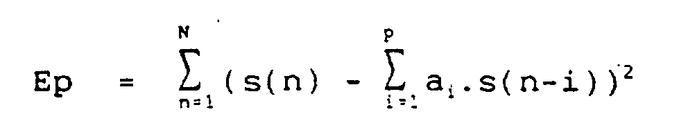
The analysis length for a digital speech signal formed by successive samples is in practice a number N of these samples, constituting a coding frame. The energy of the prediction error signal then checks the relation (2):
Dans un processus de codage par blocs, la trame de codage peut être avantageusement divisée en plusieurs sous-trames ou blocs LPC adjacents. La longueur d'analyse N excède alors la longueur de chaque bloc afin de permettre la prise en compte d'un certain nombre d'échantillons passés et, le cas échéant, futurs, au moyen et au prix de retards de codage appropriés.In a block coding process, the frame of coding can advantageously be divided into several subframes or adjacent LPC blocks. Analysis length N then exceeds the length of each block to allow the taking into account a certain number of past samples and, where applicable, future, by means and at the cost of delays appropriate coding.
L'analyse est dite LPC "avant" lorsque le processus d'analyse LPC est conduit sur le bloc de la trame courante du signal de parole à coder, le codage au niveau du codeur intervenant "en temps réel", c'est-à-dire durant le bloc de la trame courante au seul retard de traitement près introduit par le calcul des coefficients du filtre. Cette analyse implique la transmission des valeurs calculées des coefficients des filtres au décodeur.The analysis is called LPC "before" when the LPC analysis process is carried out on the block of the current frame of the speech signal to be coded, the coding at the level of the coder intervening "in real time", that is to say say during the block of the current frame to the sole processing delay introduced by calculating the coefficients of the filter. This analysis involves the transmission of the calculated values of the coefficients of the filters to the decoder.
L'analyse LPC "arrière" mise en oeuvre dans le codeur LD-CELP à 16 kb/s a fait l'objet de la norme UIT-T G728. Cette technique d'analyse consiste à effectuer l'analyse LPC, non pas sur la ou le bloc de la trame courante du signal de parole à coder, mais sur le signal de synthèse. On comprend alors que cette analyse LPC est effectuée en fait sur le signal de synthèse du bloc précédant le bloc courant, car ce signal est disponible simultanément au niveau du codeur et du décodeur. Cette opération simultanée au codeur et au décodeur permet ainsi d'éviter la transmission du codeur vers le décodeur de la valeur, obtenue au codeur, des coefficients du filtre LPC. Pour cette raison, l'analyse LPC "arrière" permet de libérer du débit de transmission, le débit ainsi libéré pouvant être employé par exemple afin d'enrichir les dictionnaires d'excitation dans le cas du codage CELP. L'analyse LPC "arrière" autorise en outre une augmentation de l'ordre d'analyse, le nombre de coefficients du filtre LPC pouvant atteindre 50 dans le cas d'un codeur LD-CELP contre 10 coefficients pour la plupart des codeurs mettant en oeuvre une analyse LPC "avant". The "rear" LPC analysis implemented in the LD-CELP coder at 16 kb / s is the subject of standard ITU-T G728. This analysis technique consists in performing the LPC analysis, not on the block or the block of the current frame of the speech signal to be coded, but on the synthesis signal. It will then be understood that this LPC analysis is in fact carried out on the synthesis signal of the block preceding the current block, since this signal is available simultaneously at the level of the coder and the decoder. This simultaneous operation with the coder and the decoder thus makes it possible to avoid the transmission from the coder to the decoder of the value, obtained at the coder, of the coefficients of the LPC filter. For this reason, the “ backward ” LPC analysis makes it possible to free up the transmission rate, the rate thus freed up being able to be used for example in order to enrich the excitation dictionaries in the case of CELP coding. The “ backward ” LPC analysis also allows an increase in the order of analysis, the number of coefficients of the LPC filter being able to reach 50 in the case of an LD-CELP coder against 10 coefficients for most coders implementing performs a " before " LPC analysis.
Ainsi, un bon fonctionnement de l'analyse LPC "arrière" exige les conditions suivantes :
- bonne qualité du signal de synthèse, très proche du signal de parole à coder, ce qui implique un débit de codage suffisamment élevé, supérieur à 13 kb/s compte tenu de la qualité actuelle des codeurs CELP ;
- trame et bloc de longueur réduite en raison du retard d'un bloc entre signal analysé et signal à coder. La longueur de trame et de bloc doit donc être faible par rapport au temps de stationnarité moyen du signal de parole à coder ;
- fidélité de la transmission et respect de l'intégrité des données transmises entre codeur et décodeur, par l'introduction de peu d'erreurs de transmission. Dès que les signaux de synthèse diffèrent de manière significative du signal de parole à coder, codeur et décodeur ne calculent plus le même filtre et des divergences importantes peuvent survenir, en l'absence de toute chance de retour à une sensible identité des filtres calculés au codeur ou au décodeur.
- good quality of the synthesis signal, very close to the speech signal to be coded, which implies a sufficiently high coding bit rate, greater than 13 kb / s taking into account the current quality of CELP coders;
- frame and block of reduced length due to the delay of a block between the analyzed signal and the signal to be coded. The frame and block length must therefore be small compared to the average stationarity time of the speech signal to be coded;
- fidelity of the transmission and respect for the integrity of the data transmitted between encoder and decoder, by the introduction of few transmission errors. As soon as the synthesis signals differ significantly from the speech signal to be coded, the coder and decoder no longer calculate the same filter and significant divergences may occur, in the absence of any chance of returning to a sensitive identity of the filters calculated at encoder or decoder.
En raison des avantages et inconvénients respectifs des types d'analyse précités LPC "arrière" et "avant", une technique consistant à associer sélectivement l'analyse LPC "arrière" et "avant" a été proposée dans l'article intitulé : "Dual Rate Low Delay CELP Coding (8 kbits/s/16 kbits/s) using a Mixed Backward/Forward Adaptive LPC Prediction" publié par S.PROUST, C.LAMBLIN et D.MASSALOUX, Proc.IEEE Workshop Speech Cod. Telecomm., Sept. 1995, pp 37-38. Les conditions préalablement mentionnées, relatives au bon fonctionnement de l'analyse LPC "arrière", révèlent que ce seul type d'analyse présente des limites manifestes lorsqu'on opère à des débits de transmission nettement inférieurs à 16 kb/s. Outre la diminution de qualité du signal de synthèse, laquelle dégrade les performances du filtre LPC, il est le plus souvent nécessaire, afin de réduire le débit de transmission, d'opérer sur une longueur de trame LPC plus importante, de l'ordre de 10 à 30 ms. On constate alors que dans ces conditions, la dégradation intervient avent tout lors des transitions de spectre de fréquences et plus généralement dans les zones peu stationnaires, alors que pour des signaux globalement très stationnaires comme ceux relatifs à la musique, l'analyse LPC "arrière" conserve un avantage très significatif vis-à-vis de l'analyse LPC "avant.". Due to the respective advantages and disadvantages of the aforementioned types of LPC analysis "rear" and "front", a technique consisting in selectively combining the LPC analysis "rear" and "front" was proposed in the article entitled: "Dual Rate Low Delay CELP Coding (8 kbits / s / 16 kbits / s) using a Mixed Backward / Forward Adaptive LPC Prediction " published by S.PROUST, C.LAMBLIN and D.MASSALOUX, Proc.IEEE Workshop Speech Cod. Telecomm., Sept. 1995, pp 37-38. The conditions previously mentioned, relating to the proper functioning of the " rear " LPC analysis, reveal that this only type of analysis has obvious limits when operating at transmission rates significantly lower than 16 kb / s. In addition to the reduction in the quality of the synthesis signal, which degrades the performance of the LPC filter, it is most often necessary, in order to reduce the transmission rate, to operate on a longer LPC frame length, of the order of 10 to 30 ms. It can then be seen that under these conditions, the degradation occurs before all during frequency spectrum transitions and more generally in areas with little stationary, while for generally very stationary signals such as those relating to music, the LPC analysis "rear " retains a very significant advantage over LPC analysis " before. ".
L'association des deux types d'analyse LPC précités a pour objet de pallier ces inconvénients en bénéficiant des avantages inhérents à chacun d'eux :
- analyse LPC "avant" pour le codage des transitions et des zones non-stationnaires ;
- analyse LPC "arrière", d'ordre plus élevé, pour le codage des zones stationnaires.
- " forward " LPC analysis for coding transitions and non-stationary areas;
- higher order "back" LPC analysis for coding stationary areas.
En outre, l'introduction de trames LPC codées par analyse LPC "avant" parmi des trames LPC codées par analyse LPC "arrière" permet au codeur et au décodeur de converger à nouveau vers un même signal de synthèse en cas d'erreur de transmission et offre donc une robustesse à ces erreurs très supérieure à un codage par analyse LPC "arrière" pur.In addition, the introduction of LPC frames coded by " forward " LPC analysis among LPC frames coded by "back" LPC analysis allows the coder and the decoder to converge again to the same synthesis signal in the event of transmission error. and therefore offers a robustness to these errors much superior to a coding by pure "back" LPC analysis.
Globalement, l'analyse LPC mixte "avant"-"arrière"
précitée consiste à effectuer deux analyses LPC, une analyse
LPC "avant" sur le signal de parole ou audiofréquence à
coder et une analyse LPC "arrière" sur le signal de synthèse.
Deux filtres sont calculés pour chaque bloc LPC, ces filtres
étant désignés par filtre LPC "avant" et filtre LPC "arrière"
respectivement. Une procédure de choix du filtre
appliqué pour le bloc LPC considéré en fonction de la
stationnarité du signal est alors mise en oeuvre. Cette
procédure fait appel à deux critères distincts :
- un premier critère fondé sur les gains de prédiction des filtres :
- un deuxième critère fondé sur un paramètre de distance entre filtres LPC "avant" calculés successivement. Pour chacun de ces deux critères, des valeurs de seuil, fixes, sont établies.
Two filters are calculated for each LPC block, these filters being designated by " front " LPC filter and " rear " LPC filter respectively. A procedure for choosing the filter applied for the LPC block considered as a function of the stationarity of the signal is then implemented. This procedure uses two separate criteria:
- a first criterion based on the filter prediction gains:
- a second criterion based on a distance parameter between LPC filters " before " calculated successively. For each of these two criteria, fixed threshold values are established.
Le choix du filtre LPC "arrière" est retenu si l'écart entre le gain de prédiction des filtres LPC "arrière" et "avant" est supérieur à une première valeur de seuil.The choice of the "rear" LPC filter is retained if the difference between the prediction gain of the "rear" and "front" LPC filters is greater than a first threshold value.
Pour une analyse courante en mode d'analyse LPC "arrière", interdiction du basculement du mode d'analyse LPC "arrière" en mode d'analyse LPC "avant" si la distance calculée sur les vecteurs de paramètres représentant deux filtres LPC "avant" consécutifs est inférieure à une deuxième valeur de seuil, une distance trop faible caractérisant une zone sensiblement stationnaire pour laquelle il est opportun d'éviter tout changement de mode d'analyse LPC. La distance calculée est une distance euclidienne entre les raies spectrales du signal de parole ou audiofréquence à coder.For a current analysis in "back" LPC analysis mode , prohibition of switching from "back" LPC analysis mode to "front" LPC analysis mode if the distance calculated on the parameter vectors representing two " front " LPC filters "consecutive is less than a second threshold value, a too small distance characterizing a substantially stationary zone for which it is advisable to avoid any change in LPC analysis mode. The calculated distance is a Euclidean distance between the spectral lines of the speech or audio frequency signal to be coded.
Pour une description plus détaillée du mode d'analyse LPC mixte précité, on pourra utilement se reporter à l'article publié par S.PROUST, C.LAMBLIN et D.MASSALOUX précédemment cité.For a more detailed description of the analysis mode LPC mixed above, we can usefully refer to the article published by S.PROUST, C.LAMBLIN and D.MASSALOUX previously cited.
Des investigations approfondies menées sur le mode opératoire de l'analyse mixte précitée ont permis de mettre en évidence les inconvénients importants ci-après :
- pour certains signaux, les valeurs des gains de prédiction des filtres LPC "avant" et "arrière" peuvent osciller de part et d'autre de la première valeur de seuil. Ce phénomène occasionne des changements de filtre LPC "arrière" - LPC "avant", ou réciproquement, brusques et fréquents. Les discontinuités de filtrage alors introduites constituent une source de dégradation importante du signal de synthèse et ne sont pas, la plupart du temps, liées à des réelles modifications spectrales du signal de parole ou audiofréquence à coder ;
- la valeur optimale du premier seuil, qu'il convient de fixer, varie très fortement en fonction de la stationnarité du signal à coder, ce d'autant plus que le débit de codage est faible. Pour un retard de codage correspondant à une trame LPC de 10 à 30 ms, ou lorsque le débit de transmission diminue, il apparaít une divergence très nette du mode de codage de signaux de musique et de parole. Pour les signaux de musique, l'analyse LPC "arrière" est utilisée quasiment en permanence alors que pour les signaux de parole, l'analyse LPC "avant" est utilisée majoritairement.
- le filtre LPC qui donne la meilleure qualité subjective et modélise donc le mieux le spectre du signal à coder n'est pas toujours celui qui possède le meilleure gain de prédiction. Certains basculements d'un mode d'analyse LPC à l'autre, liés à une décision instantanée, sont donc inutiles.
- for certain signals, the values of the prediction gains of the “front” and “rear” LPC filters can oscillate on either side of the first threshold value. This phenomenon causes abrupt and frequent LPC filter changes "rear" - LPC "front", or vice versa. The filtering discontinuities then introduced constitute a source of significant degradation of the synthesis signal and are not, most of the time, linked to real spectral modifications of the speech or audio frequency signal to be coded;
- the optimal value of the first threshold, which should be fixed, varies very greatly as a function of the stationarity of the signal to be coded, all the more so when the coding rate is low. For a coding delay corresponding to an LPC frame of 10 to 30 ms, or when the transmission rate decreases, there appears a very clear divergence in the coding mode of music and speech signals. For music signals, the "back" LPC analysis is used almost continuously while for speech signals, the " front " LPC analysis is used mostly.
- the LPC filter which gives the best subjective quality and therefore best models the spectrum of the signal to be coded is not always the one with the best prediction gain. Certain switches from one LPC analysis mode to another, linked to an instant decision, are therefore unnecessary.
La présente invention a pour objet de remédier aux inconvénients précités par la mise en oeuvre d'un procédé et d'un dispositif de codage d'un signal numérique audiofréquence par analyse LPC "avant" et "arrière" spécifique.The object of the present invention is to remedy the aforementioned drawbacks by implementing a method and a device for coding a digital audio frequency signal by specific " front " and "rear" LPC analysis.
Un autre objet de la présente invention est également la mise en oeuvre d'un processus d'adaptation dynamique de la fonction de choix entre l'analyse LPC "avant" et l'analyse LPC "arrière" en fonction du degré de stationnarité du signal à coder.Another object of the present invention is also the implementation of a process of dynamic adaptation of the function of choice between the "front" LPC analysis and the "rear" LPC analysis according to the degree of stationarity of the signal. to code.
Un autre objet de la présente invention est également la mise en oeuvre d'un processus d'adaptation dynamique de la fonction de choix précitée sur la base d'une discrimination entre signaux fortement stationnaires, tels que musique ou bruit de fond, et autres signaux, tels que la parole, afin de permettre le traitement de codage le plus approprié par analyse LPC "arrière" et "avant" respectivement.Another object of the present invention is also the implementation of a process of dynamic adaptation of the aforementioned choice function on the basis of a discrimination between strongly stationary signals, such as music or background noise, and other signals. , such as speech, to allow the most appropriate coding processing by "back" and "front" LPC analysis respectively.
Un autre objet de la présente invention est également, le choix du codage le plus approprié précité ayant été effectué, pour un signal à coder d'un type ou de caractéristiques donnés, d'éviter tout basculement intempestif dans le mode d'analyse LPC non retenu, et, ainsi, d'éviter l'apparition de transitions de filtres LPC "avant" - "arrière" ou réciproquement susceptibles de dégrader la qualité du signal de synthèse reproduit.Another object of the present invention is also, the choice of the aforementioned most appropriate coding having been carried out, for a signal to be coded of a given type or characteristics, to avoid any untimely switchover in the non-LPC analysis mode. retained, and, thus, to avoid the appearance of transitions of LPC filters " front " - " rear " or vice versa likely to degrade the quality of the reproduced synthesis signal.
Un autre objet de la présente invention est enfin la misé en oeuvre d'un processus d'adaptation dynamique de la fonction de choix précitée pour lequel le changement de mode d'analyse LPC correspond de manière fidèle à un changement de stationnarité du signal à coder et risque, en conséquence, d'être beaucoup moins lié à un simple effet de franchissement ponctuel des première et deuxième valeurs de seuil.Another object of the present invention is finally the implemented a process of dynamic adaptation of the above-mentioned choice function for which the mode change LPC analysis is a true reflection of a change stationarity of the signal to be coded and risks, therefore, to be much less linked to a simple crossing effect point of the first and second threshold values.
Le procédé et le dispositif de codage d'un signal
numérique audiofréquence, objets de la présente invention,
mettent en oeuvre une double analyse sur critère de choix
d'analyse LPC "avant" et "arrière" respectivement pour
engendrer un signal codé transmis consistant en des paramètres
de filtrage LPC accompagnés d'une information de
décision d'analyse et un signal de résidu de codage, non
transmis. Le signal numérique audiofréquence est subdivisé
en trames, succession de blocs d'un nombre déterminé
d'échantillons et le codage de ce signal numérique audiofréquence
est effectué sur ce signal à partir d'un filtrage LPC
"avant" pour les zones non stationnaires et sur un signal de
synthèse respectivement, ce signal de synthèse étant obtenu
à partir du signal résidu de codage, à partir d'un filtrage
LPC "arrière" pour les zones stationnaires.
Ils sont remarquables en ce qu'ils consistent à, et permettent
de, respectivement :
- déterminer le degré de stationnarité du signal numérique audiofréquence selon un paramètre de stationnarité, dont la valeur est comprise entre une valeur de stationnarité maximale et une valeur de stationnarité minimale ;
- établir une valeur de choix d'analyse, en appliquant une fonction de décision adaptative au paramètre de stationnarité ;
- appliquer la valeur de choix d'analyse au filtrage LPC pour effectuer le codage du signal numérique audiofréquence par filtrage LPC "avant" pour les zones non-stationnaires sur le signal numérique audiofréquence et par filtrage LPC "arrière" pour les zones stationnaires sur le signal de synthèse.
They are remarkable in that they consist of and allow, respectively:
- determining the degree of stationarity of the digital audio frequency signal according to a stationarity parameter, the value of which lies between a maximum stationarity value and a minimum stationarity value;
- establishing an analysis choice value, by applying an adaptive decision function to the stationarity parameter;
- apply the analysis choice value to the LPC filtering to carry out the coding of the digital audio signal by "front" LPC filtering for non-stationary zones on the digital audio signal and by "rear" LPC filtering for stationary zones on the signal of synthesis.
Le procédé et le dispositif, objets de la présente invention, trouvent application non seulement au domaine de la téléphonie mobile mais également à l'industrie de la création et de la reproduction de phonogrammes, à la transmission par satellite et à la téléphonie haute qualité pour des applications de visio- ou audio-conférence, multimédia.The method and the device, objects of the present invention find application not only in the field of mobile telephony but also to the industry creation and reproduction of phonograms, at the high quality satellite and telephone transmission for video or audio conference applications, multimedia.
Ils seront mieux compris à la lecture de la description et à l'observation des dessins ci-après, dans lesquels :
- la figure 1 représente, sous forme d'un organigramme général, un schéma illustratif des étapes permettant la mise en oeuvre du procédé de codage, objet de la présente invention ;
- la figure 2a représente un organigramme général des étapes de calcul du paramètre de stationnarité pour chaque bloc LPC courant ;
- la figure 2b représente un mode de réalisation particulier avantageux des étapes essentielles du calcul du paramètre de stationnarité selon la figure 2a ;
- la figure 2c représente un détail de réalisation de la figure 2b, plus particulièrement un détail du processus d'affinage de la valeur du paramètre de stationnarité intermédiaire pour l'obtention du paramètre de stationnarité ;
- les figures 2d et 2e représentent un premier, respectivement un deuxième exemple de réalisation non limitatif de mise en oeuvre d'une fonction d'affinage permettant de calculer une valeur d'affinage du paramètre de stationnarité intermédiaire en fonction des valeurs relatives du gain de filtrage LPC "avant" et "arrière" ;
- la figure 2f représente, à titre d'exemple illustratif, un organigramme des étapes permettant la mise en oeuvre de la fonction de décision et de la valeur du choix d'analyse LPC "avant" ou "arrière" ;
- la figure 3 représente, sous forme de blocs fonctionnels, le schéma général d'un codeur permettant d'effectuer le codage d'un signal audiofréquence conformément à l'objet de la présente invention ;
- la figure 4 représente, sous forme de blocs fonctionnels, le schéma général d'un décodeur permettant d'effectuer le décodage d'un signal audiofréquence codé grâce à la mise en oeuvre d'un codeur tel que représenté en figure 3.
- FIG. 1 represents, in the form of a general flowchart, an illustrative diagram of the steps allowing the implementation of the coding method, object of the present invention;
- FIG. 2a represents a general flow diagram of the steps for calculating the stationarity parameter for each current LPC block;
- FIG. 2b represents a particular advantageous embodiment of the essential steps of the calculation of the stationarity parameter according to FIG. 2a;
- FIG. 2c represents a detail of embodiment of FIG. 2b, more particularly a detail of the process of refining the value of the intermediate stationarity parameter for obtaining the stationarity parameter;
- FIGS. 2d and 2e represent a first, respectively a second nonlimiting example of implementation of a refining function making it possible to calculate a refining value of the intermediate stationarity parameter as a function of the relative values of the filtering gain LPC "front" and "rear" ;
- FIG. 2f represents, by way of illustrative example, a flow diagram of the steps allowing the implementation of the decision function and of the value of the LPC analysis choice " front " or "back" ;
- FIG. 3 represents, in the form of functional blocks, the general diagram of an encoder making it possible to carry out the coding of an audio frequency signal in accordance with the object of the present invention;
- FIG. 4 represents, in the form of functional blocks, the general diagram of a decoder making it possible to carry out the decoding of an audio-coded signal signal thanks to the implementation of an encoder as represented in FIG. 3.
Une description plus détaillée du procédé de codage d'un signal numérique audiofréquence par double analyse, sur critère de choix d'analyse LPC "avant" respectivement "arrière" en un signal codé transmis, objet de la présente invention, sera maintenant donnée en liaison avec la figure 1.A more detailed description of the coding method of a digital audio signal by double analysis, on the criterion of choice of LPC analysis " front " or "rear" respectively into a coded transmitted signal, object of the present invention, will now be given in connection with figure 1.
D'une manière générale, on indique que le signal codé transmis, noté s_cn(t), consiste pour partie en des paramètres de filtrage LPC accompagnés d'une information de décision d'analyse LPC. En outre, un signal de résidu de codage resn(t) non transmis est disponible par la mise en oeuvre du procédé de codage.In general, it is indicated that the transmitted coded signal, noted s_c n (t), consists partly of LPC filtering parameters accompanied by LPC analysis decision information. In addition, a non-transmitted coding residue signal res n (t) is available by the implementation of the coding method.
Le signal numérique audiofréquence est subdivisé en trames LPC, succession de blocs LPC, chaque bloc, pour la commodité de la description, étant noté Bn et muni d'un nombre N déterminé d'échantillons.The digital audio frequency signal is subdivided into LPC frames, a succession of LPC blocks, each block, for the convenience of the description, being denoted B n and provided with a determined number N of samples.
Conformément à un aspect du procédé de codage, objet de la présente invention, celui-ci consiste à effectuer le codage précité sur le signal numérique audiofréquence tel que défini précédemment à partir d'un filtrage LPC "avant" pour les zones non stationnaires, respectivement sur un signal de synthèse obtenu à partir du signal résidu de codage à partir d'un filtrage LPC "arrière" pour les zones stationnaires.In accordance with one aspect of the coding method which is the subject of the present invention, it consists in carrying out the aforementioned coding on the digital audio frequency signal as defined above from " forward " LPC filtering for the non-stationary areas, respectively on a synthesis signal obtained from the residual coding signal from a "rear" LPC filtering for stationary areas.
Selon un aspect particulièrement remarquable du
procédé objet de la présente invention, celui-ci consiste,
afin d'établir le critère de choix de filtrage LPC "avant"
ou "arrière", sur chaque bloc courant de la succession de
blocs courants constituant une trame courante, ainsi que
représenté en figure 1, chaque bloc courant, noté Bn, étant
disponible en une étape de départ 10, à déterminer en une
étape 11 le degré de stationnarité du signal numérique
audiofréquence selon un paramètre de stationnarité, noté
STAT(n). Ce paramètre de stationnarité présente une valeur
numérique comprise entre une valeur de stationnarité
maximale, notée STATM, et une valeur de stationnarité
minimale, notée STATm.According to a particularly remarkable aspect of the method which is the subject of the present invention, it consists, in order to establish the criterion of choice of LPC filtering "front" or "rear", on each current block of the succession of current blocks constituting a frame current, as shown in FIG. 1, each current block, denoted B n , being available in a starting
Par convention et sans nuire aucunement au degré de généralité du procédé de codage objet de la présente invention, on indique que le paramètre de stationnarité présente la valeur maximale STATM pour un signal très fortement stationnaire, alors que ce paramètre de stationnarité présente la valeur minimale STATm pour un signal très fortement non stationnaire.By convention and without in any way detracting from the degree of generality of the coding method which is the subject of the present invention, it is indicated that the stationarity parameter has the maximum value STAT M for a very strongly stationary signal, while this stationarity parameter has the minimum value STAT m for a very strongly non-stationary signal.
Suite à l'étape 11 précitée, le procédé de codage
objet de la présente invention consiste à établir, en une
étape 12, à partir du paramètre de stationnarité STAT(n),
une valeur de choix d'analyse LPC, cette valeur de choix
d'analyse correspondant bien entendu, soit au choix de
l'analyse LPC "avant", soit au contraire au choix de
l'analyse LPC "arrière". La valeur de choix d'analyse est
notée dn(n) et est obtenue à partir d'une fonction de
décision spécifique, notée Dn.Following the
L'étape 12 précitée est alors suivie d'une étape de
test 13 permettant l'application de la valeur de choix
d'analyse dn(n), symbolisée par C, au filtrage LPC pour
effectuer le codage du signal numérique audiofréquence par
filtrage LPC "avant" pour les zones non-stationnaires sur le
signal numérique audiofréquence, respectivement par filtrage
LPC "arrière" pour les zones stationnaires sur le signal de
synthèse.The above-mentioned
La mise en oeuvre de la fonction de décision Dn et des valeurs de choix d'analyse précitées dn(n), conformément à un aspect particulièrement avantageux du procédé de codage objet de la présente invention, permet de privilégier le maintien dans l'un des modes de filtrage LPC "avant" respectivement "arrière", en liaison avec le degré de stationnarité du signal audiofréquence, et de limiter le nombre de basculements de l'un à l'autre des modes de filtrage, et réciproquement.The implementation of the decision function D n and of the abovementioned analysis choice values d n (n), in accordance with a particularly advantageous aspect of the coding method which is the subject of the present invention, makes it possible to favor maintenance in the one of the LPC filtering modes "front" respectively "rear", in connection with the degree of stationarity of the audio frequency signal, and to limit the number of switches from one to the other of the filtering modes, and vice versa.
D'une manière générale, on indique que la fonction
de décision mise en oeuvre à l'étape 12, cette fonction de
décision étant notée Dn, est une fonction adaptative
actualisée pour chaque bloc courant Bn, à partir du paramètre
de stationnarité.In general, it is indicated that the decision function implemented in
L'actualisation de la fonction adaptative permet de privilégier le maintien dans l'un des modes de filtrage LPC "avant", respectivement "arrière", en fonction du degré de stationnarité du signal numérique audiofréquence et de limiter ainsi le nombre de basculements de l'un à l'autre des modes de filtrage, et réciproquement.The updating of the adaptive function makes it possible to privilege the maintenance in one of the LPC filtering modes "front", respectively "rear" , according to the degree of stationarity of the digital audio-frequency signal and thus limit the number of toggles of l 'to one another filtering modes, and vice versa.
D'une manière plus spécifique, on indique que la valeur de choix d'analyse dn(n) établie à partir de la fonction de décision Dn précitée correspond à une valeur de priorité de mode de filtrage LPC "avant" ou "arrière" ainsi qu'à une autre valeur de priorité représentant en fait une valeur d'absence de priorité de retour au mode de filtrage LPC "arrière" ou "avant". More specifically, it is indicated that the analysis choice value d n (n) established from the above-mentioned decision function D n corresponds to a filtering mode priority value LPC " front " or "rear " as well as to another priority value representing in fact a value of absence of priority to return to the LPC filtering mode " rear " or " front ".
Par valeur de priorité de mode de filtrage LPC, on
indique que la valeur de choix d'analyse dn(n) peut par
exemple correspondre à une valeur logique, la valeur vraie
de cette valeur logique, valeur 1 par exemple, correspondant
à un choix de filtrage LPC "arrière" alors que la valeur
complémentée de cette valeur vraie, la valeur zéro, correspond
à un choix de filtrage LPC "avant". On comprend ainsi
que la fonction de test à l'étape 13 peut se résumer à une
valeur de test sur la valeur logique de la valeur de choix
d'analyse précitée pour assurer à l'étape 14 le filtrage LPC
"arrière" pour les zones stationnaires du signal à coder ou
le filtrage LPC "avant" à l'étape 15 pour les zones non-stationnaires,
les étapes 14 et 15 précitées étant alors
suivies par les étapes 14a et 15a au retour au bloc suivant
noté Bn-1, pour n = n+1.By LPC filtering mode priority value, it is indicated that the analysis choice value d n (n) can for example correspond to a logical value, the true value of this logical value,
Bien que la valeur de choix d'analyse dn(n) soit représentée par une valeur logique, on comprend que cette valeur logique peut être associée à une valeur de priorité et de probabilité de mode de filtrage établie par la fonction de décision Dn de manière spécifique. On comprend en particulier que cette valeur de probabilité peut correspondre, pour chaque bloc courant Bn, à la valeur logique vraie pour une plage de valeurs de probabilité comprise entre zéro et 1 de filtrage LPC "arrière" alors que la valeur logique complémentée, valeur logique zéro par exemple, peut correspondre au complément de la plage de valeurs de probabilité précitée entre zéro et 1 de la première plage précitée. Cette probabilité est liée au nombre de décisions successives de filtrage dans un même mode de filtrage.Although the analysis choice value d n (n) is represented by a logical value, it is understood that this logical value can be associated with a priority and probability value of filtering mode established by the decision function D n specifically. It is understood in particular that this probability value can correspond, for each current block B n , to the true logic value for a range of probability values between zero and 1 for "backward" LPC filtering whereas the complemented logic value, value logic zero, for example, may correspond to the complement of the above range of probability values between zero and 1 of the first aforementioned range. This probability is linked to the number of successive filtering decisions in the same filtering mode.
Le mode opératoire de la fonction de décision Dn permettant en fait d'associer à la variable logique dn(n) la valeur de priorité de mode de filtrage, est adaptatif au cours du temps, pour chaque bloc courant Bn.The operating mode of the decision function D n making it possible in fact to associate with the logic variable d n (n) the priority of filtering mode, is adaptive over time, for each current block B n .
D'une manière générale, on indique que l'adaptation de la fonction de décision Dn a pour but de privilégier progressivement le mode de filtrage LPC "arrière" ou au contraire le mode de filtrage LPC "avant" qui fonctionne le mieux, compte tenu de la stationnarité globale du signal à coder, afin d'éviter le plus possible tout basculement inutile d'un des modes de filtrage à l'autre.In general, it is indicated that the adaptation of the decision function D n aims to progressively favor the "back" LPC filtering mode or on the contrary the "front" LPC filtering mode which works best, counts given the overall stationarity of the signal to be coded, in order to avoid as much as possible any unnecessary switching from one of the filtering modes to the other.
De manière plus spécifique, on indique que :
- plus le signal à coder est stationnaire et plus la fonction de décision Dn privilégie l'analyse LPC "arrière" en limitant le plus possible le basculement en mode d'analyse LPC "avant",
- au contraire, moins le signal à coder est stationnaire et plus la fonction de décision Dn privilégie l'analyse LPC "avant" en limitant le plus possible tout basculement en mode d'analyse LPC "arrière".
- the more the signal to be coded is stationary and the more the decision function D n favors the " back " LPC analysis by limiting as much as possible the switch to " forward " LPC analysis mode,
- on the contrary, the less the signal to be coded is stationary and the more the decision function D n favors the " forward " LPC analysis by limiting as much as possible any switch to "backward" LPC analysis mode .
Une description plus détaillée de mise en oeuvre d'une fonction de décision spécifique permettant de réaliser l'adaptation de cette fonction de décision, en fonction de la valeur du paramètre de stationnarité STAT(n), sera donnée ultérieurement dans la description.A more detailed description of implementation a specific decision function allowing to realize the adaptation of this decision function, depending on the value of the stationary parameter STAT (n), will be given later in the description.
Un mode de calcul préférentiel du paramètre de stationnarité STAT(n) relatif à chaque bloc LPC courant Bn sera maintenant donné et décrit en liaison avec la figure 2a.A preferred method of calculating the stationarity parameter STAT (n) relative to each current LPC block B n will now be given and described in connection with FIG. 2a.
Selon la figure précitée, on indique que l'étape 11
consistant à déterminer le degré de stationnarité de chaque
bloc courant Bn du signal numérique audiofréquence consiste,
à partir d'une valeur arbitraire de départ du paramètre de
stationnarité, ainsi que représenté à l'étape 110 de la
figure 2a, cette valeur arbitraire étant notée STAT(O), à
calculer en une étape 111 pour ce bloc courant Bn une valeur
de paramètre de stationnarité intermédiaire, notée STAT*(n),
fonction d'un nombre déterminé de valeurs de choix d'analyse
successives, ces valeurs de choix d'analyse LPC, notées
dn-1(n-1), ..., à dn-p(n-p), étant obtenues pour différents
blocs successifs antérieurs au bloc courant Bn de la
succession de blocs LPC, et de la valeur du paramètre de
stationnarité du bloc précédant le bloc courant, cette
valeur de stationnarité étant notée STAT(n-1). A l'étape 111
représentée en figure 2a, on indique que la fonction du
nombre déterminé de valeurs de choix d'analyse antérieures
est donnée en relation avec ces valeurs antérieures, notées
dn-1(n-1) à dn-p(n-p). En ce qui concerne la valeur arbitraire
de départ du paramètre de stationnarité STAT(0), on indique
que celui-ci peut, à titre d'exemple non limitatif, être
pris égal à la valeur moyenne entre la valeur maximale et la
valeur minimale du paramètre de stationnarité précédemment
mentionnées dans la description, STATM et STATm.According to the aforementioned figure, it is indicated that
L'étape 111 précitée est alors suivie d'une étape
112, laquelle consiste à affiner la valeur du paramètre de
stationnarité intermédiaire en fonction de la valeur des
gains de prédiction des filtres ou mode d'analyse LPC
"avant" et "arrière" de la trame précédant la trame courante.
A l'étape 112 de la figure 2a, on indique que la
fonction précitée est notée g(STAT*(n),Gpf,Gpb) où Gpf
désigne le gain de prédiction du filtre LPC "avant" et Gpb
désigne le gain de prédiction du filtre LPC "arrière" pour
la trame précédant la trame courante. A l'étape 112, c'est-à-dire
en fin d'étape consistant à affiner la valeur du
paramètre de stationnarité intermédiaire, à la valeur de
paramètre de stationnarité STAT(n) du bloc LPC courant Bn
est attribuée la valeur, relation (3) :
Une description plus détaillée de l'étape de calcul
111 du paramètre de stationnarité intermédiaire STAT*(n) et
de l'étape 112 consistant à affiner cette valeur de paramètre
sera maintenant donnée en liaison avec la figure 2b.A more detailed description of the
Conformément à la figure précitée, l'étape 111
consiste, à partir d'une étape d'initialisation 1110 dans
laquelle la valeur du paramètre de stationnarité STAT(n-1)
et la valeur de choix d'analyse dn-1(n-1) relatives au bloc
LPC Bn-1 antérieur au bloc courant Bn est disponible, à
effectuer, en une étape 1111, une étape consistant à
discriminer le mode d'analyse LPC "avant" ou LPC "arrière"
du bloc Bn-1 précédant le bloc courant Bn. Cette étape de
discrimination 1111 peut, ainsi que représenté en figure 2b,
consister en une étape de test sur la valeur de choix
d'analyse dn-1(n-1) par rapport à la valeur symbolique "fwd"
ou à la valeur logique zéro correspondant à la valeur
complémentée de la valeur logique vraie.In accordance with the aforementioned figure, step 111 consists, from an
Sur réponse négative au test 1111 précité, c'est-à-dire
pour tout bloc Bn-1 précédant le bloc courant LPC Bn
analysé en mode d'analyse LPC "arrière", l'étape de calcul
de la valeur de paramètre de stationnarité intermédiaire
consiste, en une étape 1113, à déterminer le nombre de
trames antérieures analysées consécutivement en mode
d'analyse LPC "arrière", nombre noté N_BWD, puis, en une
étape 1114, à comparer sur critère de comparaison de
supériorité le nombre de trames antérieures à une première
valeur arbitraire, notée Na, représentative d'un nombre de
trames successives analysées en mode LPC "arrière". On negative response to the aforementioned test 1111, that is to say for any block B n-1 preceding the current block LPC B n analyzed in “backward” LPC analysis mode , the step of calculating the parameter value of intermediate stationarity consists, in a
Sur réponse positive à la comparaison de supériorité
du test 1114, l'étape de calcul consiste alors à attribuer,
en une étape 1114b, à la valeur de paramètre de stationnarité
intermédiaire STAT*(n), la valeur du paramètre de
stationnarité du bloc précédant le bloc courant, STAT(n-1),
augmentée d'une valeur déterminée fonction de la première
valeur arbitraire représentative d'un nombre de trames
successives analysées, c'est-à-dire en fait du nombre de
trames antérieures N_BWD analysées consécutivement en mode
d'analyse LPC "arrière". A l'étape 1114b, la valeur déterminée
fonction de la première valeur arbitraire est notée
fa(N_BWD). Au cours de l'étape précitée, on comprend que la
valeur du paramètre de stationnarité intermédiaire STAT*(n)
pour le bloc LPC courant Bn est ainsi augmentée par rapport
à la valeur correspondante du même paramètre de stationnarité
pour le bloc précédent Bn-1.On a positive response to the comparison of superiority of
Sur réponse négative à la comparaison de supériorité
au test de comparaison 1114, à la valeur de paramètre de
stationnarité intermédiaire STAT*(n) est attribuée, en une
étape 1114a, la valeur du paramètre de stationnarité STAT(n-1)
du bloc précédant le bloc courant Bn.On a negative response to the comparison of superiority to the
Au contraire, pour tout bloc précédent Bn-1 analysé
en mode d'analyse LPC "avant", c'est-à-dire sur réponse
positive au test 1111, l'étape de calcul du paramètre de
stationnarité intermédiaire 111 consiste, ainsi que représenté
en figure 2b, à déterminer en une étape 1112, sur
critère de test, l'occurrence d'une transition du mode
d'analyse LPC "arrière" en mode d'analyse LPC "avant" entre
le bloc antérieur au bloc antérieur au bloc courant Bn-1, de
rang n-2, c'est-à-dire l'existence d'une valeur de choix
d'analyse LPC dn-2(n-2) = valeur symbolique "bwd", soit
valeur logique zéro ainsi que mentionné précédemment. La
réponse positive au test 1112 indique l'existence d'une
telle transition du mode d'analyse "arrière" pour le bloc
LPC Bn-2 précédant le bloc précédant le bloc courant Bn-1,
alors qu'une réponse négative au test 1112 précité indique
l'absence d'une telle transition.On the contrary, for any previous block B n-1 analyzed in LPC analysis mode "before", that is to say on a positive response to test 1111, the step of calculating the
Sur réponse positive au test d'occurrence 1112
précité, l'étape de calcul 111 consiste ensuite à comparer,
sur critère de comparaison d'infériorité, le nombre de
trames antérieures N_BWD précitées à une deuxième valeur
arbitraire Nb représentative d'un nombre de trames successives
analysées en mode LPC "arrière" précédant le bloc Bn-1
précédant le bloc courant.On a positive response to the
Sur réponse positive à la comparaison réalisée au
test 1118, ce test est suivi d'une étape 1118a consistant à
attribuer à la valeur de paramètre de stationnarité intermédiaire
STAT*(n) la valeur du paramètre de stationnarité du
bloc précédant le bloc courant, STAT(n-1) diminuée d'une
valeur déterminée, fonction de la deuxième valeur arbitraire
Nb, cette valeur déterminée étant notée fb(N_BWD). On
comprend ainsi qu'au cours de l'étape 1118a d'attribution,
la valeur du paramètre de stationnarité intermédiaire est
ainsi diminuée en conséquence.On a positive response to the comparison carried out in
Au contraire, sur réponse négative à la comparaison
d'infériorité effectuée au test 1118, l'étape 111 consiste
alors à attribuer, en une étape 1118b, à la valeur du
paramètre de stationnarité intermédiaire STAT*(n) la valeur
de paramètre de stationnarité du bloc précédant le bloc
courant, soit STAT(n-1).On the contrary, on a negative response to the comparison
of inferiority carried out in
Sur la figure 2b, on remarquera que les étapes
d'attribution 1118a et 1118b sont alors suivies d'une étape
de remise à zéro du nombre de blocs successifs traités en
mode d'analyse LPC "arrière", cette étape de mise à zéro
portant la référence 1118c et permettant de réactualiser
l'ensemble du processus de calcul de la valeur du paramètre
de stationnarité intermédiaire.In FIG. 2b, it will be noted that the allocation steps 1118a and 1118b are then followed by a step for resetting to zero the number of successive blocks processed in "backward" LPC analysis mode , this step of zeroing carrying the
Sur réponse négative au test de comparaison 1112,
aucune transition analyse LPC "avant" n'étant apparue, à la
valeur du paramètre de stationnarité intermédiaire STAT*(n)
est attribuée la valeur du paramètre de stationnarité
STAT(n-1) du bloc précédent Bn-1 en une étape 1119.On a negative response to
A la fin de l'étape 111, on dispose de la valeur du
paramètre de stationnarité intermédiaire STAT*(n) pour le
bloc courant Bn.At the end of
En ce qui concerne l'étape 112 consistant à affiner
la valeur du paramètre de stationnarité intermédiaire
précitée, on indique, en référence à la figure 2b, que
celle-ci peut consister avantageusement, en une étape 1120,
à discriminer les gains de prédiction du filtrage LPC
"arrière" et du filtrage LPC "avant", ces valeurs de gain
étant notées Gpb et Gpf respectivement. On comprend que
l'étape de discrimination précitée consiste simplement à
mémoriser et à lire les valeurs de gain calculées pour le
filtrage LPC "avant" respectivement "arrière" précité. Outre
les valeurs de gain précitées, l'étape 1120 peut consister
à calculer la valeur relative des gains de prédiction, notée
DGfb, telle que la différence ou le rapport entre les gains
de prédiction "avant" et "arrière" précités.As regards step 112 consisting in refining the value of the aforementioned intermediate stationarity parameter, it is indicated, with reference to FIG. 2b, that this can advantageously consist, in a
Ainsi qu'on l'a représenté en outre en figure 2b,
l'étape 112 de la figure 2a comprend à la suite de l'étape
1120 précitée une étape 1121 consistant à modifier la valeur
du paramètre de stationnarité intermédiaire STAT*(n) d'une
valeur d'affinage ΔS, cette valeur d'affinage conformément
à une caractéristique particulièrement remarquable du
procédé objet de la présente invention étant fonction de la
valeur relative des gains de prédiction de filtrage LPC
"avant" et "arrière". As shown in addition in FIG. 2b, step 112 of FIG. 2a comprises, after the above-mentioned
D'une manière générale, on indique que la fonction représentative de la valeur d'affinage ΔS est notée :
- ΔS = fr(Gpf, Gpb) où Gpf et Gpb désignent ainsi que précédemment les gains de prédiction du filtrage LPC "avant" respectivement "arrière".
- ΔS = f r (Gpf, Gpb) where Gpf and Gpb thus designate as previously the prediction gains of the LPC filtering "front" respectively "rear".
D'une manière générale, on indique que la fonction fr(GPf, Gpb) permettant d'établir la valeur d'affinage ΔS est une fonction croissante respectivement décroissante de cette valeur relative, selon le sens dans lequel on considère cette valeur relative. Lorsque la valeur relative désigne la valeur du gain de filtrage LPC "arrière" par rapport au gain de filtrage LPC "avant", ce choix peut être arbitrairement retenu sans nuire aucunement à la généralité du procédé, objet de l'invention, valeur relative DGfb prcitée, la fonction fr est alors croissante. Elle est décroissante dans le cas contraire.In general, it is indicated that the function f r (GPf, Gpb) making it possible to establish the refinement value ΔS is an increasing respectively decreasing function of this relative value, according to the direction in which this relative value is considered. When the relative value designates the value of the "back" LPC filtering gain compared to the "front" LPC filtering gain , this choice can be arbitrarily retained without in any way detracting from the generality of the process, object of the invention, relative value DGfb above, the function f r is then increasing. Otherwise, it decreases.
En d'autres termes, la modification, par augmentation ou par diminution, de la valeur du paramètre de stationnarité intermédiaire de la valeur d'affinage ΔS est proportionnelle à cette valeur relative des gains. D'une manière générale, cette modification s'écrit STAT(n) = STAT*(n) + kΔS. En pratique on prendra k = 1. D'une manière plus spécifique, on indique que la valeur d'affinage ΔS augmente en valeur algébrique lorsque l'écart entre les gains de prédiction du filtrage LPC "avant" et "arrière" augmente, la fonction fr(GPf, Gpb) étant alors une fonction croissante, alors que cette valeur d'affinage ΔS diminue en valeur algébrique lorsque ce même écart précité diminue, l'écart précité étant défini entre le gain de prédiction du filtrage LPC "arrière" et le gain de prédiction du filtrage LPC "avant". En fait, cette fonction est croissante ou décroissante selon la définition de cet écart.In other words, the modification, by increase or by decrease, of the value of the intermediate stationarity parameter of the ripening value ΔS is proportional to this relative value of the gains. Generally, this modification is written STAT (n) = STAT * (n) + kΔS. In practice we will take k = 1. In a more specific way, we indicate that the refinement value ΔS increases in algebraic value when the difference between the prediction gains of the LPC filtering "front" and "rear" increases, the function f r (GPf, Gpb) then being an increasing function, while this refinement value ΔS decreases in algebraic value when this same abovementioned deviation decreases, the abovementioned deviation being defined between the "backward" LPC filtering prediction gain and the LPC filtering prediction gain " before ". In fact, this function is increasing or decreasing depending on the definition of this difference.
En conséquence, en fin d'étape 1121 ainsi que représenté
sur la figure 2b, la valeur du paramètre de stationnarité
intermédiaire STAT*(n) peut alors, pour k = 1, être
corrigée par la valeur algébrique de la valeur d'affinage ΔS
précitée pour calculer la valeur du paramètre de stationnarité
STAT(n).Consequently, at the end of
Suite à l'étape 1121, on dispose ainsi de la valeur
du paramètre de stationnarité STAT(n) à l'étape 1122.Following
Une description plus détaillée de l'étape 1121 de la
figure 2b sera maintenant donnée en liaison avec la figure
2c dans un mode de réalisation préférentiel dans lequel une
pluralité de critères de tests sont appliqués tant à la
valeur d'affinage qu'aux valeurs de gain de prédiction LPC
"avant" et "arrière" en vue d'optimiser le processus de
calcul du paramètre de stationnarité.A more detailed description of
Ainsi que représenté sur la figure 2c précitée,
l'étape 1121 peut consister en une première étape 1121a
permettant de calculer la valeur d'affinage ΔS à partir de
la fonction fr(Gpf, Gpb) précédemment citée. Différents
exemples de fonctions utilisables seront donnés ultérieurement
dans la description. As shown in FIG. 2c above,
En premier lieu, la valeur d'affinage ΔS est soumise
à un test de comparaison de supériorité à la valeur 0, en
une étape 1121b, ce test de comparaison permettant en fait
de déterminer l'accroissement de cette valeur d'affinage ΔS.First, the refinement value ΔS is subject
to a comparison test of superiority to the
Sur réponse positive au test 1121b précité, la valeur d'affinage ΔS étant positive et correspondant à un accroissement de la valeur relative des gains de prédiction du filtrage LPC "avant" et "arrière", l'étape d'augmentation de la valeur du paramètre de stationnarité intermédiaire de la valeur d'affinage ΔS est en outre soumise à une condition de supériorité de la valeur de gain de filtrage LPC "arrière", par rapport à une première valeur positive déterminée, en une étape de comparaison de supériorité de la valeur du gain de filtrage LPC "arrière" Gpb par rapport à cette première valeur positive déterminée, notée Si.On a positive response to the aforementioned test 1121b, the refinement value ΔS being positive and corresponding to an increase in the relative value of the LPC filtering prediction gains " front " and " rear ", the step of increasing the value of intermediate stationarity parameter of the refinement value ΔS is further subject to a condition of superiority of the “ backward ” filtering gain value LPC, compared with a first determined positive value, in a step of comparing the superiority of the value of the "back" LPC filtering gain Gpb with respect to this first determined positive value, denoted S i .
Sur réponse négative au test 1121c précité, à la
valeur du paramètre de stationnarité STAT(n) est attribuée
la valeur du paramètre de stationnarité intermédiaire
STAT*(n) en une étape 1121g.On a negative response to the
Sur réponse positive au test 1121c précité, l'augmentation
de la valeur du paramètre de stationnarité
intermédiaire de la valeur d'affinage ΔS est en outre
soumise à une condition d'infériorité de la valeur du
paramètre de stationnarité intermédiaire STAT*(n) par
rapport à une deuxième valeur positive déterminée STATi
représentant bien entendu une valeur de stationnarité. Ce
test de condition d'infériorité est réalisé à l'étape 1121e.On a positive response to the
Sur réponse négative au test 1121e précité, à la
valeur du paramètre de stationnarité intermédiaire STAT(n)
est attribuée la valeur du paramètre de stationnarité
intermédiaire STAT*(n) à l'étape 1121g précitée.On a negative response to the
Sur réponse positive au test de condition d'infériorité
1121e à la valeur du paramètre de stationnarité
intermédiaire STAT(n) est attribuée la valeur du paramètre
de stationnarité intermédiaire STAT*(n) augmentée de la
valeur positive ΔS de la valeur d'affinage à l'étape 1121i. On positive response to the
Au contraire, sur réponse négative au test 1121b
précité, la valeur d'affinage ΔS étant négative, l'étape de
diminution du paramètre de stationnarité intermédiaire de la
valeur d'affinage ΔS, cette valeur étant négative, est en
outre soumise à un test de condition d'infériorité de la
valeur de gain du filtrage LPC "arrière" Gpb par rapport à
une troisième valeur positive déterminée notée Sd en une
étape de comparaison 1121d. Cette troisième valeur positive
déterminée est bien entendu représentative d'une valeur de
gain de filtrage LPC.On the contrary, on a negative response to the aforementioned test 1121b, the refinement value ΔS being negative, the step of decreasing the intermediate stationarity parameter by the refinement value ΔS, this value being negative, is also subjected to a test. of inferiority condition of the gain value of the "back" LPC filtering Gpb with respect to a third determined positive value denoted S d in a
Sur réponse négative au test 1121d précité à la
valeur de paramètre de stationnarité STAT(n) est attribuée
la valeur du paramètre de stationnarité intermédiaire
STAT*(n) à l'étape 1121g.On a negative response to test 1121d mentioned above in
stationary parameter value STAT (n) is assigned
the value of the intermediate stationarity parameter
STAT * (n) in
Au contraire, sur réponse positive au test 1121d précité, l'étape de diminution de la valeur du paramètre de stationnarité intermédiaire de la valeur d'affinage ΔS est en outre soumise à une condition de supériorité de la valeur du paramètre de stationnarité intermédiaire STAT*(n) par rapport à une quatrième valeur positive déterminée, notée STATd en un test de comparaison noté 1121f. Bien entendu, la quatrième valeur positive déterminée est représentative d'une valeur de paramètre de stationnarité choisie.On the contrary, on a positive response to the 1121d test mentioned above, the step of decreasing the value of the parameter of intermediate stationarity of the ripening value ΔS is further subject to a value superiority condition of the intermediate stationarity parameter STAT * (n) by compared to a fourth determined positive value, noted STATd in a comparison test noted 1121f. Of course, the fourth determined positive value is representative of a selected stationarity parameter value.
Sur réponse négative au test 1121f précité, à la
valeur de paramètre de stationnarité STAT(n) est attribuée
la valeur du paramètre de stationnarité intermédiaire
STAT*(n) à l'étape 1121g.On a negative response to the
Sur réponse positive au test 1121f précité, à la
valeur de paramètre de stationnarité STAT(n) est attribuée
la valeur du paramètre de stationnaritée intermédiaire STAT*
augmenté de la valeur algébrique de la valeur d'affinage ΔS,
négative, la valeur du paramètre de stationnarité intermédiaire
étant ainsi diminuée pour établir la valeur de
paramètre de stationnarité STAT(n) à l'étape 1121h.On a positive response to the
En fin des étapes 1121g, 1121h et 1121i, on dispose
ainsi à l'étape 1122 de la figure 2b du paramètre de
stationnarité STAT(n).At the end of
En ce qui concerne la fonction fr(Gpf, Gpb), on indique que celle-ci peut consister en. une fonction non linéaire de la valeur relative des gains de filtrage LPC "avant" et "arrière" dans laquelle la valeur relative des gains de prédiction du filtrage LPC "avant" et "arrière" peut elle-même consister soit en le rapport, soit en la différence des gains de prédiction du filtrage LPC "avant" et "arrière". D'autres types de fonctions, tels que des fonctions linéaires, peuvent être utilisés.With regard to the function f r (Gpf, Gpb), it is indicated that this can consist of. a non-linear function of the relative value of the "forward" and "backward" LPC filtering gains in which the relative value of the "forward" and "backward" LPC filtering prediction gains may itself consist of either the ratio or unlike the " forward " and " backward " LPC filtering prediction gains. Other types of functions, such as linear functions, can be used.
Un premier exemple de fonction non linéaire fr(Gpf, Gpb) est représenté en figure 2d.A first example of a non-linear function f r (Gpf, Gpb) is shown in Figure 2d.
Dans l'exemple de réalisation de la figure 2d, des couples de valeur du gain de prédiction du filtrage LPC "arrière" Gpb porté en ordonnée et du gain de filtrage LPC "avant" Gpf permettent d'attribuer des valeurs d'affinage ΔS positives, ΔS > 0 ou négatives ΔS < 0 pour une valeur du rapport ρ = Gpb/Gpf correspondant à une pente supérieure respectivement inférieure à celle de la droite ΔS = 0.In the exemplary embodiment of FIG. 2d, pairs of values of the LPC filtering prediction gain "rear" Gpb plotted on the ordinate and the LPC filtering gain gain " before " Gpf make it possible to assign positive refinement values ΔS , ΔS> 0 or negative ΔS <0 for a value of the ratio ρ = Gpb / Gpf corresponding to a higher slope respectively lower than that of the straight line ΔS = 0.
Sur la figure 2e, on a représenté le cas où la valeur relative des gains de prédiction de filtrage LPC "avant" et "arrière" correspond non plus au rapport des gains ρ mais à la différence des gains précités.In FIG. 2e, we have represented the case where the relative value of the LPC filtering prediction gains "front" and "rear" no longer corresponds to the ratio of the gains ρ but to the difference of the aforementioned gains.
Dans ce cas, la fonction de la valeur relative des gains de prédiction du filtrage LPC "avant" et "arrière" fr(Gpf, Gpb) peut également être une fonction non linéaire permettant d'attribuer à la valeur d'affinage ΔS pour des valeurs de cette différence correspondant à des couples de valeur Gpb, Gpf correspondant à des droites dont l'abscisse à l'origine est inférieure respectivement supérieure, en valeur algébrique, à l'abscisse à l'origine de la droite ΔS = 0.In this case, the function of the relative value of the prediction gains from the LPC filtering " front " and "rear" f r (Gpf, Gpb) can also be a non-linear function allowing the refinement value ΔS to be assigned to values of this difference corresponding to pairs of value Gpb, Gpf corresponding to straight lines whose abscissa at the origin is respectively respectively greater, in algebraic value, than the abscissa at the origin of the line ΔS = 0.
Dans le cas de la figure 2e, les droites délimitant les zones en fonction du signe de la valeur d'affinage ΔS sont parallèles entre elles.In the case of Figure 2e, the lines delimiting zones according to the sign of the ripening value ΔS are parallel to each other.
Conformément à un autre aspect particulier du
procédé objet de l'invention, on indique en outre qu'il
convient de ne pas adapter l'indice de stationnarité du bloc
courant Bn lors de trames de silence, lorsque par exemple le
signal audiofréquence est constitué par un signal de parole
comportant des silences. Dans un tel cas, l'étape 1111 de
l'étape 111 représentée en figure 2b peut être précédée par
une étape 1111a consistant, pour chaque bloc courant
successif, à déterminer l'énergie moyenne du signal numérique
audiofréquence et à comparer dans cette même étape,.sur
critère de comparaison d'infériorité, cette énergie moyenne
à une valeur de seuil déterminée représentative d'une trame
de silence. Sur la figure 2b, cette valeur de seuil est
notée ENER_SIL. Sur réponse positive au test précité, à la
valeur du paramètre de stationnarité du bloc courant STAT(n)
est attribuée le valeur du paramètre de stationnarité du
bloc précédent STAT(n-1) à l'étape d'attribution 1111b
représentée sur la figure 2b. Les étapes 1111a et 1111b
sont, sur la figure précitée, représentées en pointillé, car
réservées par exemple au codage d'un signal de parole.In accordance with another particular aspect of the method which is the subject of the invention, it is further indicated that the stationarity index of the current block B n should not be adapted during silence frames, when for example the audio frequency signal is constituted by a speech signal including silences. In such a case, step 1111 of
Une description plus détaillée de la mise en oeuvre de la fonction de décision Dn permettant l'obtention des valeurs de décision dn(n) sera maintenant donnée en liaison avec la figure 2f. Cette description est donnée dans un mode de réalisation préférentiel dans lequel cette fonction de décision, pouvant être rapprochée de celle qui est décrite dans l'article précédemment mentionné par la description, publié par S.PROUST, C.LAMBLIN et D.MASSALOUX, est toutefois adaptée temporellement, conformément à l'objet de la présente invention afin d'obtenir les valeurs de choix d'analyse dn(n) successives.A more detailed description of the implementation of the decision function D n allowing the obtaining of the decision values d n (n) will now be given in connection with FIG. 2f. This description is given in a preferred embodiment in which this decision function, which can be compared to that described in the article previously mentioned by the description, published by S.PROUST, C.LAMBLIN and D.MASSALOUX, is however adapted temporally, in accordance with the object of the present invention in order to obtain the successive analysis choice values d n (n).
A partir d'une étape 120, pour le bloc courant Bn,
on calcule en premier lieu une distance, notée dLPC, entre le
filtre LPC du bloc courant et celui du bloc précédent Bn-1.
Ce calcul de distance est effectué par exemple en utilisant
les paramètres de fréquence LSP ainsi que mentionné précédemment
dans la description relativement au procédé décrit
dans l'article précité.From a
On note :
- S_PRED(n) et S_TRANS, S_STAT et G1 les valeurs des seuils intervenant dans le critère fondé sur les gains de prédiction des filtres LPC "arrière" et "avant" ;
- S_LSP_L et S_LSP_H les valeurs des seuils intervenant dans le critère fondé sur les distances entre vecteurs de fréquence LSP représentant deux filtres. LPC "avant" relatifs à deux blocs consécutifs Bn-1 et Bn ;
- Gpf le gain de prédiction du filtre LPC "avant" ;
- Gpb le gain de prédiction du filtre "arrière" ; et
- Gpi le gain de prédiction du filtre "avant" interpolé selon la méthode exposée dans l'article publié, mentionné précédemment dans la description.
- S_PRED (n) and S_TRANS, S_STAT and G 1 the values of the thresholds intervening in the criterion based on the gains in prediction of the LPC filters "rear" and "front" ;
- S_LSP_L and S_LSP_H the values of the thresholds intervening in the criterion based on the distances between vectors of frequency LSP representing two filters. LPC " before " relating to two consecutive blocks B n-1 and B n ;
- Gpf the prediction gain of the LPC filter "before";
- Gpb the prediction gain of the "back" filter ; and
- Gpi the prediction gain of the " before " filter interpolated according to the method exposed in the published article, mentioned previously in the description.
Le critère d'établissement de la fonction de décision, en relation avec la figure 2f, est établi de la façon ci-après :
- si les filtres LPC consécutifs sont très stationnaires, c'est-à-dire pour dLPC < S_LSP_L, alors, aucun basculement du filtrage LPC "arrière" au filtrage LPC "avant" n'est réalisé si l'on est en mode de filtrage LPC "arrière", à condition que le gain de prédiction du filtre LPC "arrière" soit supérieur au gain de prédiction du filtre LPC "avant" diminué d'une valeur S_STAT. On indique que la valeur S_STAT est choisie de manière à favoriser le choix d'un filtre LPC "arrière" en présence d'une grande stationnarité du spectre mesurée à l'aide de la distance dLPC ;
- si les filtres LPC consécutifs présentent une transition importante, c'est-à-dire pour dLPC > S_LSP_H et si Gpf > Gpb-S_TRANS, alors, le mode de filtrage choisi est le filtrage LPC "avant", c'est-à-dire dn(n) = 0, valeur symbolique "fwd", sinon, dn(n) est pris égal à 1, valeur symbolique "bwd". On indique que la valeur de S_TRANS est choisie de manière à favoriser fortement le choix du filtre LPC "avant" en présence d'une transition de spectre mesurée à l'aide de la distance dLPC ;
- sinon, dans tous les autres cas, si Gpb > Gpf-S_PRED et Gpi > Gpf-S_PRED, alors, le filtre LPC retenu est le filtre LPC "arrière" interpolé, à condition que le gain de ce dernier et celui du filtre LPC "arrière" pur excèdent la valeur de seuil G1 précédemment mentionnée. Si la condition sur les valeurs de gain de prédiction précitées n'est pas remplie, alors, on choisit le filtrage LPC "avant".
- if the consecutive LPC filters are very stationary, that is to say for d LPC <S_LSP_L, then, no switching from LPC filtering " back " to LPC filtering " before " is carried out if one is in " rear " LPC filtering, provided that the prediction gain of the "rear" LPC filter is greater than the prediction gain of the "front" LPC filter reduced by a value S_STAT. It is indicated that the value S_STAT is chosen so as to favor the choice of a "rear" LPC filter in the presence of a large stationarity of the spectrum measured using the distance d LPC ;
- if the consecutive LPC filters have a significant transition, that is to say for d LPC > S_LSP_H and if Gpf> Gpb-S_TRANS, then, the filtering mode chosen is the LPC filtering "before", that is to say -d say d n (n) = 0, symbolic value "fwd" , otherwise, d n (n) is taken equal to 1, symbolic value " bwd ". It is indicated that the value of S_TRANS is chosen so as to strongly favor the choice of the LPC filter " before " in the presence of a spectrum transition measured using the distance d LPC ;
- otherwise, in all other cases, if Gpb> Gpf-S_PRED and Gpi> Gpf-S_PRED, then the LPC filter used is the interpolated "back" LPC filter, provided that the gain of the latter and that of the LPC filter " rear " pure exceed the threshold value G 1 previously mentioned. If the condition on the aforementioned prediction gain values is not fulfilled, then the “before” LPC filtering is chosen .
Afin d'augmenter le nombre de filtres LPC "avant" transmis et d'accroítre ainsi la robustesse du système de codage aux erreurs de transmission, le mode de filtrage LPC "avant" peut être choisi avantageusement dès que l'énergie du signal à coder En, c'est-à-dire l'énergie du bloc Bn correspondant, devient inférieure à la valeur de l'énergie d'une trame de silence ENER_SIL, cette valeur d'énergie correspondant au niveau audible minimum.In order to increase the number of " forward " LPC filters transmitted and thus increase the robustness of the coding system for transmission errors, the " forward " LPC filtering mode can be advantageously chosen as soon as the energy of the signal to be encoded E n , that is to say the energy of the corresponding block B n , becomes lower than the value of the energy of a frame of silence ENER_SIL, this value of energy corresponding to the minimum audible level.
L'ensemble des conditions permettant l'établissement de la fonction de décision Dn et l'obtention des valeurs de choix d'analyse dn(n) correspondante, est illustré en figure 2f avec adaptation temporelle de la fonction de décision Dn.The set of conditions allowing the establishment of the decision function D n and the obtaining of the corresponding analysis choice values d n (n), is illustrated in FIG. 2f with temporal adaptation of the decision function D n .
La valeur du paramètre de stationnarité STAT(n) peut par exemple être repérée sur une échelle de 0, correspondant à la valeur STATm très peu stationnaire, à 100, correspondant à la valeur STATM très stationnaire.The value of the stationary parameter STAT (n) can for example be located on a scale of 0, corresponding to the value STAT m very little stationary, to 100, corresponding to the value STAT M very stationary.
Selon la valeur du paramètre de stationnarité STAT(n), la fonction de décision Dn est modifiée par adaptation de la valeur des seuils.Depending on the value of the stationary parameter STAT (n), the decision function D n is modified by adapting the value of the thresholds.
Plus la stationnarité du signal augmente, plus le mode de filtrage LPC "arrière" est favorisé : les seuils S_PRED, S_LSP_L et S_LSP_H sont augmentés.The more the stationarity of the signal increases, the more the LPC filtering mode "rear" is favored: the thresholds S_PRED, S_LSP_L and S_LSP_H are increased.
A titre d'exemple non limitatif, on indique les fonctions de modification pour chaque boc LPC courant Bn des valeurs de seuil précitées :
- S_PRED(n) = fS_PRED(STAT(n)) avec fS_PRED fonction croissante de la valeur de STAT(n) ;
- S_LSP_L(n) = fS_LPC_L(STAT(n)) avec fS_LPC_L fonction croissante ;
- S_LSP_L(n) = fS_LPC_H(STAT(n)) avec fS_LPC_H fonction croissante.
- S_PRED (n) = f S_PRED (STAT (n)) with f S_PRED increasing function of the value of STAT (n);
- S_LSP_L (n) = f S_LPC_L (STAT (n)) with f S_LPC_L increasing function;
- S_LSP_L (n) = f S_LPC_H (STAT (n)) with f S_LPC_H increasing function.
Dans l'adaptation des valeurs de seuil précitées, on
indique que les fonctions croissantes mentionnées sont par
exemple des fonctions en escalier pour ce qui concerne les
fonctions fS_LPC_L et fS_LPC_H. La fonction fS_PRED est une fonction
affine de la variable paramètre de stationnarité, de la
forme :
Afin de limiter encore plus le risque de basculement des filtres, il est alors possible de choisir, lorsque le paramètre de stationnarité STAT(n) est inférieur à une valeur de seuil SFWD donnée, d'imposer le mode de filtrage LPC "avant".In order to further limit the risk of filter tilting, it is then possible to choose, when the stationarity parameter STAT (n) is less than a given threshold value S FWD , to impose the LPC filtering mode " before " .
Par contre, les valeurs de seuil S_TRANS, S_STAT et G1 conservent une valeur fixe, ces valeurs pouvant par exemple être égales à -1 dB, 5 dB et 0 dB respectivement.On the other hand, the threshold values S_TRANS, S_STAT and G 1 keep a fixed value, these values being able for example to be equal to -1 dB, 5 dB and 0 dB respectively.
L'établissement de la fonction de décision Dn et
l'obtention des valeurs de choix d'analyse dn(n) sont
illustrés de la manière suivante en figure 2f : suite à
l'étape 120 précitée, réalisation d'une étape de test 121
relative à l'énergie du bloc LPC courant Bn, par une comparaison
d'infériorité à la valeur d'énergie de silence
ENER_SIL ou de la valeur du paramètre de stationnarité
STAT(n), comparée par une comparaison d'infériorité à la
valeur SFWD précédemment citée dans la description. Sur
réponse positive au test 121 précité, la valeur de choix
d'analyse dn(n) est prise égale à 0, c'est-à-dire valeur
symbolique "fwd" à l'étape 122.The establishment of the decision function D n and the obtaining of the analysis choice values d n (n) are illustrated in the following manner in FIG. 2f: following the above-mentioned
Sur réponse négative au test 121 précité, un nouveau
test est effectué relativement à la valeur de choix d'analyse
dn-1(n-1) à la valeur logique 1, c'est-à-dire à la
valeur symbolique "bwd".On negative response to the
Sur réponse positive au test 123 précité, un nouveau
test est effectué sur la distance de filtrage LPC dLPC
précitée, en une étape 124, par rapport à la valeur de seuil
S_LSP_H(n) par comparaison de supériorité à cette valeur de
seuil.On a positive response to the
Sur réponse positive au test 124 précité, un nouveau
test 126a est réalisé, consistant à comparer le gain de
prédiction du filtrage LPC "avant", Gpf, au gain de prédiction
du filtrage LPC "arrière", Gpb, diminué de la valeur de
seuil S_TRANS.On a positive response to the
Sur réponse positive au test 126a précité, à la
valeur de choix d'analyse dn(n), est attribuée la valeur
logique 0, valeur symbolique "fwd", et sur réponse négative
au test 126a précité, est attribuée à la même valeur de
choix d'analyse la valeur logique 1, valeur symbolique
"bwd". Les étapes correspondantes sont notées 128 et 129.On a positive response to the
Sur réponse négative au test 124 précédemment
mentionné, un nouveau test 125 est réalisé. Le test 125
consiste à effectuer une comparaison de la distance du
filtrage LPC, dLPC, par comparaison d'infériorité à la valeur
de seuil S_LSP_L(n).On a negative response to the
Sur réponse positive au test 125, un nouveau test
126b est réalisé par comparaison de supériorité du gain de
prédiction de filtrage LPC "arrière" au gain de prédiction
de filtrage LPC "avant" diminué de la valeur S_STAT précédemment
citée.On a positive response to test 125, a
Sur réponse positive au test 126b, à la valeur de
choix d'analyse dn(n) est attribuée à l'étape 129 la valeur
logique 1, c'est-à-dire la valeur symbolique "bwd".On a positive response to test 126b, the value of analysis choice d n (n) is assigned in
Sur réponse négative au test 126b, à la valeur de
choix d'analyse dn(n) est attribuée la valeur logique 0,
c'est-à-dire la valeur symbolique "fwd", étape 128.On a negative response to test 126b, the value of choice of analysis d n (n) is assigned the
Au contraire, sur réponse négative au test 125, un
nouveau test est réalisé, en une étape 127, ce test consistant
à vérifier les conditions de comparaison du gain de
filtrage LPC "arrière" Gpb au gain de prédiction de filtrage
LPC "avant" diminué de la valeur de seuil S_PRED(n), de
comparaison de supériorité du gain de prédiction de filtrage
LPC intermédiaire Gpi à la valeur de gain de prédiction de
filtrage LPC "avant" diminuée de la valeur de seuil précitée
S_PRED(n) et de comparaison de supériorité du gain de
prédiction de filtrage "arrière" Gpb à la valeur de seuil
G1, ainsi que de comparaison de la valeur du gain de
prédiction de filtrage intermédiaire Gpi à la valeur de
seuil G1.On the contrary, on a negative response to test 125, a new test is carried out, in a
On indique que la réponse négative au test 123
précédemment mentionné dans la description amène également
à la réalisation du test 127 précité.We indicate that the negative response to test 123
previously mentioned in the description also brings
when carrying out the
Sur réponse positive au test 127 précédemment
mentionné, à la valeur de choix d'analyse dn(n) est attribuée
la valeur logique 1, c'est-à-dire la valeur symbolique
"bwd" à l'étape 129, alors qu'à la réponse négative au test
127 précité, à la valeur de choix d'analyse dn(n) est au
contraire attribuée la valeur logique 0, c'est-à-dire la
valeur symbolique "fwd" à l'étape 128.On a positive response to the
On dispose ainsi, grâce à la mise en oeuvre de la
fonction de décision Dn, de la valeur de choix d'analyse
dn(n) obtenue avec les valeurs logiques 1 ou 0 précitées,
ces valeurs logiques étant toutefois liées à une valeur de
priorité ou d'absence de priorité de retour au mode de
filtrage "arrière" ou "avant" en fonction de la valeur du
paramètre de stationnarité.We thus have, thanks to the implementation of the decision function D n , the value of choice of analysis d n (n) obtained with the aforementioned
Une description plus détaillée d'un dispositif de codage d'un signal numérique audiofréquence par double analyse sur critère de choix d'analyse LPC "avant" respectivement "arrière" en un signal codé transmis, conforme à l'objet de la présente invention, sera maintenant donnée en liaison avec la figure 3.A more detailed description of a device for coding a digital audio signal by double analysis on the LPC analysis selection criterion " front " respectively "rear" into a coded transmitted signal, in accordance with the object of the present invention, will now be given in connection with FIG. 3.
D'une manière pratique, on indique que le signal numérique à coder est subdivisé en trames constituées par des blocs successifs d'échantillons, chaque bloc comportant un nombre donné N d'échantillons par exemple.In a practical way, it indicates that the signal digital to be coded is subdivided into frames consisting of successive blocks of samples, each block comprising a given number N of samples for example.
Sur la figure 3, le mode de constitution du signal numérique audiofréquence à coder en blocs successifs d'échantillons Bn n'a pas été représenté car ce mode opératoire est parfaitement connu de l'état de la technique et peut être réalisé à partir d'une simple mémoire tampon, par exemple adressée en lecture périodiquement à la fréquence trame et à la fréquence bloc.In FIG. 3, the mode of constitution of the digital audio-frequency signal to be coded in successive blocks of samples B n has not been shown because this operating mode is perfectly known from the state of the art and can be carried out from 'a simple buffer memory, for example read periodically at the frame frequency and the block frequency.
Ainsi que représenté en outre sur la figure 3 précitée, le dispositif de codage objet de l'invention comprend un filtre d'analyse LPC "avant", portant la référence 1A, et un filtre d'analyse LPC "arrière", portant la référence 1B, afin de permettre de délivrer un signal codé transmis consistant en des paramètres de filtrage LPC accompagnés d'une indication de décision d'analyse, ainsi que des paramètres Prn relatifs à l'analyse harmonique et au signal d'excitation CELP.As also shown in FIG. 3 above, the coding device which is the subject of the invention comprises a " front " LPC analysis filter, bearing the reference 1A, and a "rear" LPC analysis filter , bearing the reference 1B, in order to enable a transmitted coded signal consisting of LPC filtering parameters accompanied by an analysis decision indication to be delivered, as well as parameters Pr n relating to the harmonic analysis and to the CELP excitation signal.
D'une manière générale, on indique que l'indication de décision d'analyse correspond à la valeur de choix d'analyse dn(n) telle que mentionnée précédemment dans la description. En ce qui concerne les paramètres de filtrage LPC, on indique que ceux-ci correspondent à des paramètres spécifiques, conformément au mode de mise en oeuvre du procédé de codage objet de la présente invention, ainsi qu'il sera décrit ci-après dans la description.In general, it is indicated that the analysis decision indication corresponds to the analysis choice value d n (n) as mentioned previously in the description. As regards the LPC filtering parameters, it is indicated that these correspond to specific parameters, in accordance with the mode of implementation of the coding method which is the subject of the present invention, as will be described below in the description.
Sur la figure 3, on a également représenté, dans le
dispositif de codage selon l'invention, l'existence d'un
filtre adaptatif en fonction de la valeur du paramètre de
stationnarité, ce filtre adaptatif portant la référence 1E.
Ce filtre adaptatif 1E reçoit bien entendu le signal
numérique d'origine, noté sn(t), c'est-à-dire le bloc courant
Bn. Le filtre 1E utilise les paramètres de filtrage LPC afin
de calculer le signal résiduel qui va ensuite être codé par
le module 1F. Ces paramètres LPC, ainsi que l'indication de
décision de filtrage constituent une partie du signal codé
qui est transmis au décodeur.In FIG. 3, the existence of an adaptive filter as a function of the value of the stationarity parameter has also been shown in the coding device according to the invention, this adaptive filter bearing the
En outre, ainsi que représenté sur la figure 3, le
dispositif de codage objet de la présente invention comprend
un moyen de codage, portant la référence 1F, d'un signal
résidu de codage non transmis, le signal résidu de codage,
désigné par resn(t) est directement disponible en sortie du
filtre adaptatif 1E, ce signal étant ainsi délivré à
l'entrée avec le signal numérique audiofréquence au module
de codage du signal résidu de codage non transmis, pour
engendrer un signal de résidu de synthèse, res_synn(t).In addition, as shown in FIG. 3, the coding device which is the subject of the present invention comprises a coding means, bearing the
Un module de filtrage inverse, portant la référence 1G, reçoit le signal de résidu de synthèse et permet de délivrer un signal de synthèse référencé s_synn(t).A reverse filtering module, bearing the reference 1G, receives the synthesis residue signal and makes it possible to deliver a synthesis signal referenced s_syn n (t) .
Un module de mémorisation 1H reçoit le signal de synthèse précité s_synn(t) pour délivrer le signal de synthèse précité pour le bloc antérieur au bloc courant Bn, le signal de synthèse ainsi obtenu étant désigné par s_synn-1(t). Ce signal de synthèse est délivré au filtre d'analyse LPC "arrière" portant la référence 1B sur la figure 3 précitée.A storage module 1H receives the aforementioned synthesis signal s_syn n (t) to deliver the aforementioned synthesis signal for the block prior to the current block B n , the synthesis signal thus obtained being designated by s_syn n-1 (t). This synthesis signal is delivered to the "rear" LPC analysis filter bearing the reference 1B in FIG. 3 above.
Le dispositif de codage, objet de la présente invention, tel que représenté en figure 3, permet d'effectuer un codage du signal numérique audiofréquence sur le signal numérique audiofréquence précité à partir du filtre LPC "avant" pour les zones non-stationnaires et sur le signal de synthèse précité s_synn-1(t) à partir du filtre LPC "arrière" 1B pour les zones stationnaires, ainsi qu'il sera décrit ci-après.The coding device, object of the present invention, as shown in FIG. 3, makes it possible to carry out coding of the digital audio frequency signal on the aforementioned digital audio signal using the " front " LPC filter for the non-stationary zones and on the aforementioned synthesis signal s_syn n-1 (t) from the “rear” LPC filter 1B for the stationary zones, as will be described below.
Ainsi qu'on l'observera sur la figure 3 précitée, le dispositif objet de l'invention comporte dans ce but, pour chaque bloc LPC courant Bn, un module de calcul 1C du degré de stationnarité du signal numérique audiofréquence selon un paramètre de stationnarité dont la valeur est comprise entre une valeur de stationnarité maximale et une valeur de stationnarité minimale. Bien entendu, le paramètre de stationnarité est le paramètre STAT(n) précédemment décrit dans la description conformément au procédé de codage objet de la présente invention. Les valeurs de stationnarité maximale et minimale sont également définies précédemment.As will be observed in FIG. 3 above, the device which is the subject of the invention comprises for this purpose, for each current LPC block B n , a module 1C for calculating the degree of stationarity of the digital audio signal according to a parameter of stationarity whose value is between a maximum stationarity value and a minimum stationarity value. Of course, the stationarity parameter is the STAT (n) parameter previously described in the description in accordance with the coding method which is the subject of the present invention. The maximum and minimum stationarity values are also defined above.
Ainsi qu'on l'a représenté en outre en figure 3, le
dispositif de codage objet de l'invention comprend un
module, noté 1D1, d'établissement à partir du paramètre de
stationnarité précité STAT(n) d'une fonction de décision et
d'une valeur de choix d'analyse LPC, la fonction de décision
étant notée Dn ainsi que mentionné précédemment dans la
description, et la valeur de choix d'analyse LPC étant bien
entendu et correspondant à la valeur de choix d'analyse LPC
notée dn(n) précédemment décrite dans la description. On
rappelle que la valeur de choix d'analyse dn(n) peut prendre
les valeurs 0 ou 1, valeurs logiques, lesquelles correspondent
à la valeur symbolique de choix d'analyse "fwd" et
"bwd" pour l'analyse LPC "avant" et "arrière" respectivement.As shown in addition in FIG. 3, the coding device which is the subject of the invention comprises a module, denoted 1D 1 , for establishing from the above-mentioned stationarity parameter STAT (n) a function of decision and an LPC analysis choice value, the decision function being denoted D n as mentioned previously in the description, and the LPC analysis choice value being of course and corresponding to the choice value of LPC analysis noted d n (n) previously described in the description. It is recalled that the value of choice of analysis d n (n) can take the
On comprend en particulier qu'en ce qui concerne le moyen d'établissement de la fonction de décision Dn, celle-ci correspond à une réalisation logicielle par exemple, telle que décrite précédemment en liaison avec la figure 2f. En outre, le dispositif de codage selon l'invention tel que représenté en figure 3 comprend un module de discrimination d'analyse de filtrage LPC, noté 1D2, ce module recevant la valeur de choix d'analyse dn(n) et permettant de délivrer, pour le bloc LPC courant Bn la valeur des paramètres de filtrage LPC "arrière" respectivement "avant" en fonction de la valeur de choix d'analyse précitée. On comprend bien sûr que les paramètres d'analyse de filtrage LPC "arrière" ainsi que les paramètres de filtrage d'analyse LPC "avant" sont bien entendu disponibles sous forme numérique au niveau des filtres portant la référence 1B et 1A respectivement sur la figure 3. Ces paramètres sont désignés respectivement Afn(z) pour les paramètres d'analyse de filtrage LPC "avant" en ce qui concerne le filtre d'analyse LPC "avant", portant la référence 1A, et par Abn(z) pour les paramètres d'analyse LPC "arrière" en ce qui concerne le filtre d'analyse LPC "arrière" portant la référence 1B. Ces paramètres sont délivrés au module 1D1 et au module 1D2 respectivement.It is understood in particular that as regards the means for establishing the decision function D n , this corresponds to a software embodiment for example, as described above in connection with FIG. 2f. In addition, the coding device according to the invention as shown in FIG. 3 comprises an LPC filtering analysis discrimination module, denoted 1D 2 , this module receiving the analysis choice value d n (n) and allowing to deliver, for the current LPC block B n, the value of the LPC filtering parameters "rear" respectively "front" according to the above-mentioned analysis choice value. It will of course be understood that the " back " LPC filtering analysis parameters as well as the " front " LPC analysis filtering parameters are of course available in digital form at the filters bearing the reference 1B and 1A respectively in the figure. 3. These parameters are designated respectively Af n (z) for the LPC filter analysis parameters "before" with regard to the LPC analysis filter " before ", bearing the reference 1A, and by Ab n (z) for the "rear" LPC analysis parameters with regard to the "rear" LPC analysis filter bearing the reference 1B. These parameters are delivered to the 1D 1 module and to the 1D 2 module respectively.
En ce qui concerne la réalisation matérielle du module de discrimination 1D2, on indique que celui-ci peut par exemple, dans un mode de réalisation non limitatif, consister en deux zones mémoires distinctes permettant la mémorisation des paramètres de filtrage Afn(z) et Abn(z) respectivement, la valeur de choix d'analyse dn(n) en fonction de sa valeur actuelle logique, 0 ou 1, permettant l'adressage en lecture des valeurs de paramètres de filtrage mémorisés par le module 1D2 par exemple et la transmission de ces paramètres de filtrage par ce dernier.With regard to the hardware embodiment of the discrimination module 1D 2 , it is indicated that it can for example, in a non-limiting embodiment, consist of two distinct memory zones allowing the memorization of the filtering parameters Af n (z) and Ab n (z) respectively, the analysis choice value d n (n) as a function of its logical current value, 0 or 1, allowing the addressing in reading of the values of filtering parameters stored by the module 1D 2 for example and the transmission of these filtering parameters by the latter.
Enfin, ainsi que représenté sur la figure 3, on
indique que le dispositif de codage conforme à l'objet de la
présente invention, pour la réalisation du filtre adaptatif
en fonction de la valeur de stationnarité portant la
référence 1E, peut être réalisé par un élément de filtrage
dont la fonction de transfert, notée A(z), est établie à
partir des valeurs de paramètres de filtrage délivrés par le
module de discrimination 1D2 précédemment mentionné.Finally, as shown in FIG. 3, it is indicated that the coding device in accordance with the object of the present invention, for producing the adaptive filter as a function of the stationarity value carrying the
On comprend ainsi que le module de filtrage adaptatif
1E peut être réalisé par un filtre à coefficients
ajustables, à la valeur des coefficients de ce dernier étant
affectées les valeurs de paramètres de filtrage délivrées
par le module de discrimination 1D2 précédemment mentionné.
Le filtrage réalisé par le module 1E est ainsi de type
adaptatif en fonction du degré de stationnarité du signal
numérique audiofréquence à coder. Le module 1E délivre
ainsi, à partir du signal numérique audiofréquence d'origine
sn(t), le signal résidu de filtrage LPC désigné par resn(t) au
module de codage du résidu 1F, lequel permet alors de
délivrer le signal résidu de synthèse LPC désigné par
res_synn(t).It is thus understood that the
Enfin, le module 1G est un module de filtrage dont
la fonction de transfert est l'inverse de la fonction de
transfert du module 1E obtenue à partir des paramètres
mémorisés de cette dernière. Il reçoit le signal de résidu
de synthèse LPC res_synn(t) délivré par le module de codage
du résidu de codage délivré par le module 1F. On comprend
ainsi que le codage du signal numérique audiofréquence sn(t)
est effectué au niveau du module 1E grâce à l'analyse LPC
"avant", respectivement "arrière" réalisée par les filtres
d'analyse LPC "avant" 1A et d'analyse LPC "arrière" 1B, le
signal codé s_cn(t) consistant en la transmission des
paramètres de filtrage LPC "avant" lorsque la valeur de
choix d'analyse dn(n) a pour valeur symbolique "fwd" ainsi
que l'indication du choix d'analyse, c'est-à-dire de la
valeur du choix d'analyse précédemment citée. Ce mode
opératoire permet d'effectuer le codage du signal numérique
audiofréquence et de privilégier le maintien dans l'un des
modes de filtrage LPC "avant", respectivement "arrière", en
fonction du degré de stationnarité du signal numérique et de
limiter en outre le nombre de basculements de l'un à l'autre
des modes de filtrage considérés.Finally, the module 1G is a filtering module whose transfer function is the inverse of the transfer function of the
Un dispositif de décodage d'un signal numérique audiofréquence codé en double analyse sur critère de choix d'analyse LPC "avant", respectivement "arrière", en un signal codé transmis conformément au procédé de codage objet de la présente invention, et grâce à la mise en oeuvre d'un dispositif de codage tel que représenté en figure 3 par exemple, sera maintenant décrit en liaison avec la figure 4.A device for decoding a digital audio signal coded in double analysis on the criterion of choice of LPC analysis "front", respectively "rear", into a coded signal transmitted in accordance with the coding method object of the present invention, and thanks to the implementation of a coding device as shown in FIG. 3 for example, will now be described in conjunction with FIG. 4.
D'une manière générale, on indique que le signal
codé transmis s_cn(t) consiste pour chaque bloc d'analyse
LPC en la valeur de choix d'analyse précitée et, dans le cas
où la valeur de choix d'analyse correspond pour le bloc
d'analyse LPC considéré à une analyse LPC "avant", en les
paramètres de filtrage LPC "avant" ainsi que les paramètres
de codage du résidu de filtrage LPC, paramètres Prn, c'est-à-dire
du signal resn(t) en un signal résidu de synthèse
res_syn(t) par le module de codage du résidu 1F.In general, it is indicated that the transmitted coded signal s_c n (t) consists for each analysis block LPC in the value of choice of analysis mentioned above and, in the case where the value of choice of analysis corresponds for the LPC analysis block considered in a " before " LPC analysis, in the "before" LPC filtering parameters as well as the LPC filtering residue coding parameters, parameters Pr n , that is to say of the res signal n (t) into a synthesis residue signal res_syn (t) by the coding module of the
Ainsi que représenté sur la figure 4, on indique que
le dispositif de décodage comporte au moins un module de
synthèse, référencé 2A, du signal résidu de filtrage
recevant les paramètres de codage du résidu LPC délivré par
le module 1F. Le module 2A décode les paramètres de codage
fournis par le module 1F et délivre en conséquence un signal
de résidu de synthèse, lequel est référencé sur la figure 4
res_synn(t).As shown in FIG. 4, it is indicated that the decoding device comprises at least one synthesis module, referenced 2A, of the filtering residue signal receiving the coding parameters of the LPC residue delivered by the
Le dispositif de décodage tel que représenté en
figure 4 comporte également un module, portant la référence
2B, de filtrage inverse adaptatif en fonction du degré de
stationnarité, recevant le signal de résidu de synthèse
précédemment cité, délivré par le module 2A, et permettant
d'engendrer un signal de synthèse s_synn(t) représentatif du
signal numérique audiofréquence, ce signal constituant en
fait le signal décodé.The decoding device as shown in FIG. 4 also includes a module, bearing the
On comprend bien sûr que le module de filtrage
inverse 2B met en oeuvre les paramètres de filtrage reçus
par le décodeur du fait de la transmission, soit les
paramètres d'analyse LPC "avant" lorsque ceux-ci sont
transmis et que la décision d'analyse correspond à une
analyse LPC "avant" ou, au contraire, les paramètres
d'analyse de filtrage "arrière" ainsi qu'il sera décrit ci-après.It will of course be understood that the
Dans ce but, le dispositif de décodage objet de la présente invention comporte bien entendu un module de filtrage LPC "arrière", portant la référence 2D, recevant le signal de synthèse, c'est-à-dire le signal référencé s_synn(t) pour le bloc LPC antérieur au bloc LPC courant, ce signal de synthèse étant ainsi référencé s_synn-1(t) sur la figure 4. On comprend dans ce but que le signal de synthèse relatif au bloc courant Bn et référencé s_synn(t) peut alors être délivré au module de filtrage LPC "arrière" 2D par l'intermédiaire d'un module de mémorisation, portant la référence 2E, permettant en fait, par un adressage en lecture adaptée, de décaler la lecture du signal de synthèse à celle correspondant au bloc précédant le bloc courant Bn.To this end, the decoding device which is the subject of the present invention of course comprises a "rear" LPC filter module , carrying the 2D reference, receiving the synthesis signal, that is to say the signal referenced s_syn n (t ) for the LPC block prior to the current LPC block, this synthesis signal thus being referenced s_syn n-1 (t) in FIG. 4. It is understood for this purpose that the synthesis signal relating to the current block B n and referenced s_syn n (t) can then be delivered to the 2D "rear" LPC filtering module by means of a storage module, bearing the reference 2E, making it possible in fact, by addressing in read-appropriate mode, to offset the reading of the signal from synthesis to that corresponding to the block preceding the current block B n .
Enfin, et pour assurer le mode opératoire précité,
le dispositif de décodage objet de la présente invention,
tel que représenté en figure 4, comprend enfin un module
discriminateur portant la référence 2C, permettant d'effectuer
une discrimination de l'analyse LPC "avant", respectivement
"arrière". Le module 2C reçoit, d'une part, pour
commande de discrimination, la valeur de choix d'analyse
reçue, c'est-à-dire la valeur dn(n), et, d'autre part, les
paramètres de filtrage LPC "avant", c'est-à-dire les
paramètres Afn(z) transmis, ainsi que les paramètres de
filtrage LPC "arrière" Abn(z) obtenus au moyen du module 2D.
Le module 2C permet ainsi de délivrer, en fonction de la
valeur de choix d'analyse, c'est-à-dire de la valeur dn(n),
soit les paramètres de filtrage LPC "avant" Afn(z), soit les
paramètres de filtrage LPC "arrière" Abn(z) au module de
filtrage inverse adaptatif 2B en fonction du degré de
stationnarité.Finally, and to ensure the above-mentioned operating mode, the decoding device which is the subject of the present invention, as shown in FIG. 4, finally comprises a discriminator module bearing the
En ce qui concerne les modes de réalisation matérielle
des modules 2C et 2B, on indique que ceux-ci peuvent
simplement consister en des modules sensiblement identiques
aux modules 1D2 et 1E ou, plus particulièrement, 1G de la
figure 3.As regards the hardware embodiments of the
En ce qui concerne la réalisation effective d'un dispositif de codage conforme à l'objet de la présente invention, permettant la mise en oeuvre du procédé tel que décrit précédemment dans la description, deux modes de réalisation spécifiques ont été réalisés.Regarding the effective realization of a coding device in accordance with the subject of this invention, allowing the implementation of the method as described previously in the description, two modes of specific achievements have been made.
Le codeur proprement dit consistait en un codeur en
bande téléphonique de 300 à 3400 Hz, à un débit de 12 kb/s
de type CELP. Les trames étaient constituées sur une durée
de 10 ms pour une excitation fournie par des dictionnaire
algébriques selon la technique dite ACELP précédemment
mentionnée dans la description.The actual coder consisted of a
telephone band from 300 to 3400 Hz, at a speed of 12 kb / s
CELP type. The frames were formed over a
L'analyse LPC "avant" était une analyse d'ordre 10 et l'analyse LPC "arrière" une analyse d'ordre 30 tous les 80 échantillons.The " forward " LPC analysis was a 10-order analysis and the "back" LPC analysis a 30-order analysis every 80 samples.
Une séparation pour le codage du résidu en deux sous-blocs de 40 échantillons a été réalisée. Chaque bloc Bn comportait 80 échantillons.A separation for coding the residue into two sub-blocks of 40 samples was carried out. Each block B n contained 80 samples.
Le paramètre de stationnarité précité varie entre deux
valeurs extrêmes 0 et 100, les valeurs STATm et STATM
précitées.The above-mentioned stationarity parameter varies between two
Les fonctions d'adaptation précédemment décrites
dans la description, et en particulier les fonctions
fa(N_BWD) et fb(N_BWD) étaient telles que :
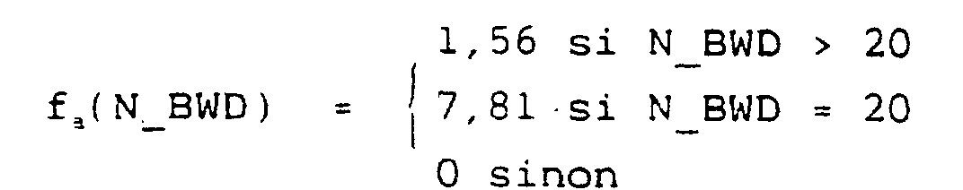
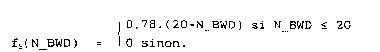
En ce qui concerne la fonction fr permettant d'établir
la valeur d'affinage ΔS précédemment mentionnée dans la
description, celle-ci est une fonction en escalier de la
variable x, avec x = Gpb - Gpf et ΔS = fr(x) et ayant pour
valeur :

L'affinage de STAT(n) est en outre soumis aux
conditions suivantes évoquées précédemment en relation avec
la figure 2c :
Si ΔS > 0 :
Si STAT*(n) < STATi STAT(n) = STAT*(n) + ΔS
Sinon STAT(n) = STAT*(n)
Sinon :
STAT(n) = STAT*(n)
avec STATi = 40,6.The refining of STAT (n) is also subject to the following conditions mentioned above in relation to FIG. 2c:
If ΔS> 0:
If STAT * (n) <STAT i STAT (n) = STAT * (n) + ΔS
Otherwise STAT (n) = STAT * (n)
If not :
STAT (n) = STAT * (n)
with STAT i = 40.6.
Les autres conditions de test référencées 1121d, 1121c et 1121f sur la figure 2c n'ont pas été utilisées dans ce mode de réalisation.The other test conditions referenced 1121d, 1121c and 1121f in Figure 2c were not used in this embodiment.
En ce qui concerne les seuils de décision :
S_PRED est adapté de la manière suivante :
S_PRED(n) = 0,03.STAT(n) + 1,0
S_PRED ∈[S_PREDm, S_PREDM], S_PREDm = 1,03 et S_PREDM = 4 ;
Le seuil S_LSP_L est adapté à l'aide de la fonction en
escalier suivante :
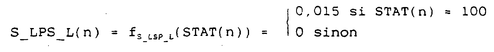
Le seuil S_LSP_H n'a pas été utilisé dans ce mode de
réalisation.
La valeur du seuil G1 a été fixée à OdB.
En ce qui concerne la valeur d'énergie caractérisant une
trame de silence ENER_SIL, cette valeur a été fixée à 40 dB
mesurée sur les 80 échantillons s(i) du bloc courant Bn :

S_PRED is adapted as follows:
S_PRED (n) = 0.03.STAT (n) + 1.0
S_PRED ∈ [S_PRED m , S_PRED M ], S_PRED m = 1.03 and S_PRED M = 4;
The threshold S_LSP_L is adapted using the following staircase function:
The threshold S_LSP_H was not used in this embodiment.
The value of the G 1 threshold has been set at OdB.
Regarding the energy value characterizing an ENER_SIL silence frame, this value was set at 40 dB measured on the 80 samples s (i) of the current block B n :
En ce qui concerne la valeur du seuil SFWD mentionné précédemment et destiné à limiter encore plus le risque de basculement en imposant le mode de filtrage LPC "avant" lorsque la valeur STAT(n) est inférieure à ce seuil, cette valeur SFWD a été fixée à 40,6.With regard to the value of the threshold S FWD mentioned above and intended to further limit the risk of switching over by imposing the LPC filtering mode " before " when the value STAT (n) is less than this threshold, this value S FWD has was set at 40.6.
- codeur en bande élargie de 0 à 7000 Hz en deux sous-bandes. Une bande principale était codée avec la technique CELP, trame de 120 échantillons, excitation créée par les dictionnaires algébriques, et transmission de certaines caractéristiques d'énergie et de spectre d'une bande hôte comprise entre 6000 Hz et 7000 Hz.wideband encoder from 0 to 7000 Hz in two subbands. A main strip was coded with the CELP technique, frame of 120 samples, excitation created by algebraic dictionaries, and transmission of certain energy and spectrum characteristics of a host band between 6000 Hz and 7000 Hz.
- analyse LPC "avant" à 14 coefficients et analyse LPC "arrière" à 50 coefficients tous les 120 échantillons. En mode d'analyse LPC "avant", séparation en deux sous-blocs LPC de 60 échantillons, le filtre utilisé pour le premier sous-bloc étant interpolé à partir du filtre courant et du filtre précédent." front " LPC analysis with 14 coefficients and " rear " LPC analysis with 50 coefficients every 120 samples. In LPC analysis mode " before ", separation into two LPC sub-blocks of 60 samples, the filter used for the first sub-block being interpolated from the current filter and the previous filter.
Dans ce mode de réalisation, le paramètre de
stationnarité précité varie entre les deux valeurs extrêmes
0 et 120, les valeurs STATm et STATM précitées.In this embodiment, the above-mentioned stationarity parameter varies between the two
En ce qui concerne l'adaptation de la valeur du
paramètre de stationnarité STAT(n), les valeurs des fonctions
fa(N_BWD) et fc(N_BWD) sont telles que :


En ce qui concerne la fonction fr permettant d'établir
la valeur d'affinage ΔS précédemment mentionnée dans la
description, celle-ci est une fonction en escalier de la
variable x, avec x = Gpb/Gpf et ΔS = fr(x) et ayant pour
valeur :
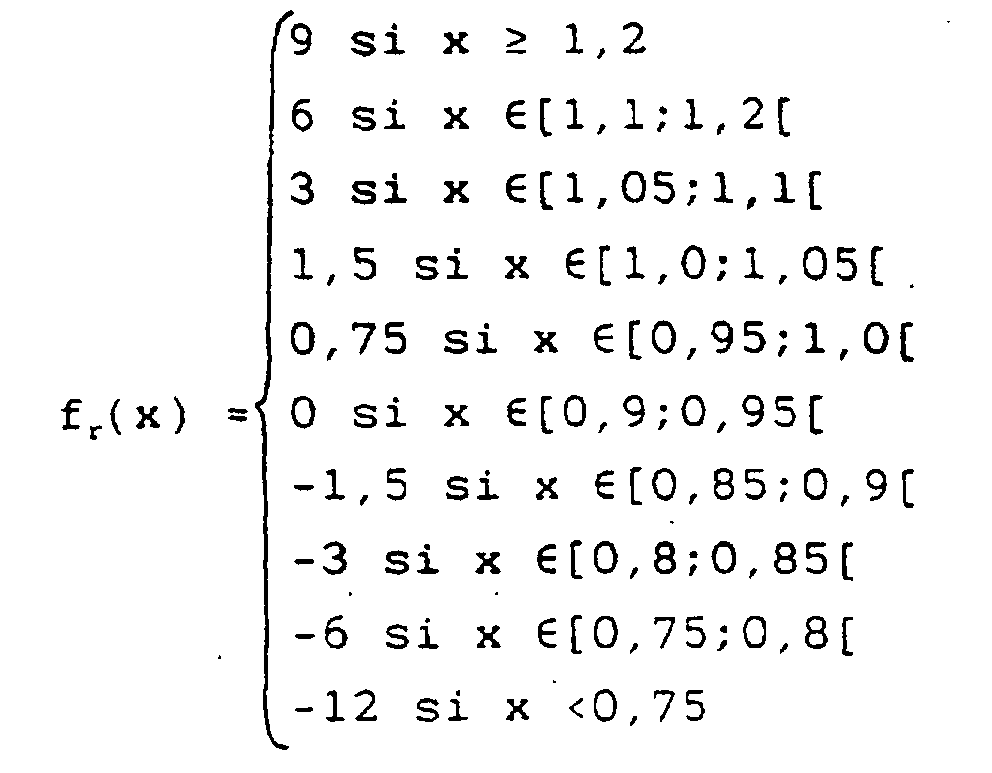
L'affinage de STAT(n) est en outre soumis aux
conditions suivantes évoquées précédemment en relation avec
la figure 2c :
Si ΔS > 0 :
Si Gpb > Si
Si STAT*(n) < STATi STAT(n) = STAT*(n) + ΔS
Sinon STAT(n) = STAT*(n)
Sinon STAT(n) = STAT*(n)
Sinon :
Si STAT*(n) < STATi STAT(n) = STAT*(n) + ΔS
Sinon STAT(n) = STAT*(n)
avec STATi = 80, Si = 0dB.The refining of STAT (n) is also subject to the following conditions mentioned above in relation to FIG. 2c:
If ΔS> 0:
If Gpb> If
If STAT * (n) <STAT i STAT (n) = STAT * (n) + ΔS
Otherwise STAT (n) = STAT * (n)
Otherwise STAT (n) = STAT * (n)
If not :
If STAT * (n) <STAT i STAT (n) = STAT * (n) + ΔS
Otherwise STAT (n) = STAT * (n)
with STAT i = 80, S i = 0dB.
Les autres conditions de test référencées 1121h et 1121d de la figure 2c n'ont pas été utilisées dans ce mode de réalisation.The other test conditions referenced 1121h and 1121d of figure 2c were not used in this mode of achievement.
En ce qui concerne les seuils de décision :
S_PRED est adapté de la manière suivante :
S_PRED(n) = 0,03.STAT(n) - 0,5 borné dans l'intervalle
[S_PREDm, S_PREDM],
avec S_PREDm = 0,5 et S_PREDM = 2,5.
Le seuil S_LSP_L est adapté à l'aide de la fonction en
escalier suivante :
![]()
![]()
La valeur du seuil S_STAT utilisée en cas de stationnarité
des filtres LPC mesurée à l'aide du seuil S_LSP_L a été
fixée à 2,5 dB.
La valeur du seuil G1 a été fixée à 0dB.
En ce qui concerne la valeur d'énergie caractérisant une
trame de silence ENER_SIL, cette valeur a été fixée à 50 dB
mesurée sur les 120 échantillons s(i) du bloc courant Bn :

S_PRED is adapted as follows:
S_PRED (n) = 0.03.STAT (n) - 0.5 bounded in the interval
[S_PRED m , S_PRED M ],
with S_PRED m = 0.5 and S_PRED M = 2.5.
The threshold S_LSP_L is adapted using the following staircase function: ![]()
![]()
The value of the threshold S_STAT used in case of stationarity of the LPC filters measured using the threshold S_LSP_L was fixed at 2.5 dB.
The value of the threshold G 1 has been set at 0dB.
Regarding the energy value characterizing an ENER_SIL silence frame, this value was fixed at 50 dB measured on the 120 samples s (i) of the current block B n :
En ce qui concerne la valeur du seuil SFWD mentionné précédemment et destiné à limiter encore plus le risque de basculement en imposant le mode de filtrage LPC "avant" lorsque la valeur STAT(n) est inférieure à ce seuil, cette valeur SFWD a été fixée à 60.With regard to the value of the threshold S FWD mentioned above and intended to further limit the risk of switching over by imposing the LPC filtering mode " before " when the value STAT (n) is less than this threshold, this value S FWD has was set at 60.
Claims (14)
- A method for encoding a digital audio signal by dual analysis according to a choice criterion of LPC "forward' and "backward' analysis respectively into a transmitted encoded signal consisting of LPC filtering parameters accompanied by analysis decision information, and into a residue encoding signal, not transmitted, said digital audio signal being subdivided into frames, a succession of blocks of a specified number of samples, the encoding of said digital audio signal being carried out on this signal through a "forward' LPC filtering for non-stationary zones respectively on a synthesis signal, obtained from said residue encoding signal, through a "backward" LPC filtering for stationary zones, said choice criterion consisting, on each current block of said succession of current blocks constituting a current frame:in defining the degree of stationarity (STAT(n)) of the digital audio signal according to a stationarity parameter, the value of which lies between a maximum stationarity value and a minimum stationarity value;in establishing an analysis choice value (dn(n)), by applying a decision function (Dn) adaptive to said stationarity parameter;in applying said analysis choice value to the "forward' LPC filtering so as to carry out the encoding of the said digital audio signal by "forward" LPC filtering for non-stationary zones on said digital audio signal, and by "backward' LPC filtering respectively for stationary zones on said synthesis signal, which makes it possible to favor the maintenance of the digital audio signal in one of the "forward" and "backward" filtering modes respectively in relation to the degree of stationarity and to limit the amount of switching from one to the other and vice versa of the filtering modes.
- A method according to claim 1, characterized in that said decision function is an adaptive function, actualized for each current block from the stationarity parameter, said actualization of said adaptive function making it possible to favor the maintenance of the digital audio signal filtering in one of the "forward" and "backward" filtering modes respectively as a function of the degree of stationarity of said digital audio signal and thus to limit the amount of switching from one to the other and vice versa of the filtering modes.
- A method according to one of claims 1 or 2, characterized in that said analysis choice value established from said decision function corresponds to a "forward" LPC filtering mode priority value and a "backward' LPC filtering mode priority value respectively.
- A method according to one of claims 1 to 3, characterized in that the stage consisting in specifying the degree of stationarity of each current block of said digital audio signal consists, starting from an arbitrary starting value of said stationarity parameter:in calculating for the said current block an intermediate stationarity parameter value, as a function of a specified number of analysis choice values, obtained for different successive blocks prior to the said current block of the said succession of blocks, and of the stationarity parameter value of the block preceding the said current block;in tuning said intermediate stationarity parameter value as a function of the value of prediction gains of the "forward" and "backward' LPC filterings of the frame preceding said current frame.
- A method according to claim 4, characterized in that the stage consisting, for each current block, in calculating an intermediate stationarity parameter value consists:in discriminating between the "forward' LPC or "backward' LPC analysis mode of the block preceding the said current block; andfor any previous block analyzed by "backward' LPC analysis mode:in specifying the number of previous frames consecutively analyzed in "backward" LPC analysis mode,in comparing, according to a superiority comparison criterion, said number of previous frames with a first arbitrary value representative of a number of successive frames analyzed in "backward" LPC mode, and on positive response to this superiority comparison,attributing to said intermediate stationarity parameter value the stationarity parameter value of the block preceding the said current block, augmented by a specified value function of said first arbitrary value, and on negative response to this superiority comparison,attributing to said intermediate stationarity parameter value the stationarity parameter value of the block preceding the current block; andfor any previous block analyzed in "forward' LPC analysis mode,in specifying according to a test criterion the occurrence of a transition from "backward" LPC analysis mode to "forward' LPC analysis mode between the block prior to said preceding block and said preceding block, and on positive response to the said test of occurrence,in comparing, according to an inferiority comparison criterion, said number of previous frames with a second arbitrary value representative of a number of successive frames analyzed in "backward" LPC mode preceding said preceding block, and on positive response to said inferiority comparison,attributing to said intermediate stationarity parameter value the stationarity parameter value of said block preceding the current block, reduced by a specified value which is a function of said second arbitrary value, and on negative response to said inferiority comparison,attributing to said intermediate stationarity parameter value the stationarity parameter value of said preceding block.
- A method according to claim 4 or 5, characterized in that the stage consisting for each current block in tuning said intermediate stationarity parameter value consists:in distinguishing between prediction gains of the "forward' LPC filtering and "backward' LPC filtering;in modifying the intermediate stationarity parameter value of a refining value function of the relative value of prediction gains of "forward' and "backward' LPC filtering, the modification, increase or reduction, of the intermediate stationarity parameter value being proportional to said refining value.
- A method according to claim 6, characterized in that the stage of increase proportional to said refining value of the intermediate stationarity parameter value is moreover subject to a condition of superiority of said value of "backward' LPC filtering gain relative to a first specified positive value and to a condition of inferiority of the value of said intermediate stationarity parameter value relative to a second specified positive value.
- A method according to claim 6 or 7, characterized in that the stage of reduction proportional to said refining value of the intermediate stationarity parameter value is moreover subject to a condition of inferiority of said value of "backward' LPC filtering gain relative to a third specified positive value and to a condition of superiority of the value of said intermediate stationarity parameter value relative to a fourth specified positive value.
- A method according to one of claims 6 to 8, characterized in that said relative value of the prediction gains of "forward' and "backward" LPC filtering consists in the ratio or the difference between prediction gains of "forward" and "backward" LPC filtering.
- A method according to one of claims 1 to 3, characterized in that it consists in addition, for each successive current block:in establishing the average energy of said digital audio signal,in comparing, according to an inferiority comparison criterion, said average energy with a specified threshold value representative of a silence frame, and on positive response to said inferiority comparison,in attributing to said stationarity parameter of the current block the stationarity parameter value of the preceding block.
- A method according to one of claims 2 to 10, characterized in that, for a degree of stationarity represented by a stationarity parameter between a minimum value and a maximum value, said minimum value representing the degree of stationarity of a substantially non-stationary digital signal and said maximum value representing the degree of stationarity of a substantially stationary signal, said adaptive function constituting the decision function is an increasing function of the priority value of the "backward' LPC filtering mode according to the increasing degree of stationarity of said digital signal.
- An encoding device for a digital audio signal by dual analysis according to a choice criterion of "forward' and "backward" LPC analysis respectively into a transmitted encoded signal, said digital signal being subdivided into frames constituted by successive blocks comprising a specified number of samples, said encoding device comprising a "forward" LPC analysis filter and a "backward' LPC filter enabling delivery of a transmitted encoded signal consisting of LPC filtering parameters accompanied by an analysis decision indication and a means of encoding an encoding residue signal, not transmitted, enabling generation of a synthesis residue signal, the encoding of said digital audio signal being carried out on this digital audio signal from the "forward' LPC filter for non-stationary zones and on this synthesis signal, from the "backward" LPC filter respectively for stationary zones, said encoding device comprising in addition, for each current LPC block;calculation means of the degree of stationarity (STAT(n)) of said digital audio signal, according to a stationarity parameter the value of which is between a maximum stationarity value and a minimum stationarity value;setting means, from a stationarity parameter, of an adaptive decision function (Dn) enabling an LPC analysis choice value to be set (dn(n));discrimination means of LPC analysis receiving said analysis choice value and enabling delivery, for said LPC current block, of the value of the "backward" and "forward" LPC filtering parameters respectively as a function of said analysis choice value;adaptive filtering means as a function of the degree of stationarity receiving said digital audio signal and the value of the "forward" and "backward' LPC filtering parameters respectively as a function of said analysis choice value and delivering the encoding residue signal to said encoding means of the encoding residue signal, which makes it possible to encode said digital audio signal and to favor the maintenance of said digital audio signal in one of the "forward" and "backward" filtering modes respectively in relation to the degree of stationarity of said digital signal and to limit the amount of switching from one to the other and vice versa of the filtering modes.
- An encoding device according to claim 12, characterized in that said transmitted encoded signal consists, for each LPC analysis block, of:said analysis value,
and in the case where the analysis choice value corresponds for LPC analysis block considered, to a "forward" LPC analysis;said "forward' LPC filtering parameters. - A decoding device of a digital audio signal encoded by dual analysis according to a choice criterion of "forward" and "backward' LPC analysis respectively, by an encoding device according to one of the claims 12 or 13, into a transmitted encoded signal consisting of LPC filtering parameters accompanied by an analysis decision value, said transmitted encoded signal consisting for each LPC analysis block of said analysis choice value and corresponding for an LPC analysis block considered to a "forward' LPC analysis in "forward' LPC filtering parameters, and for an LPC analysis block considered to a "backward' LPC analysis in "backward' LPC filtering parameters,
said decoding device comprising at least:synthesis means for the filtering residue signal receiving the said encoding parameters of the LPC residue and delivering a synthesis residue signal,reverse filtering adaptive means as a function of the degree of stationarity, receiving the synthesis residue signal and enabling generation of a synthesis signal representative of the digital audio signal and constituting the decoded signal,"backward' LPC analysis means receiving said synthesis signal and enabling generation of "backward' LPC filtering parameters,discriminating means between "forward' LPC analysis and "backward" LPC analysis respectively receiving, on the one hand, for discrimination control said analysis choice value and, on the other hand, the "forward" LPC filtering parameters and the "backward' LPC filtering parameters and enabling delivery as a function of said analysis choice value, of either "forward" LPC filtering parameters, or "backward" LPC filtering parameters to said reverse filtering adaptive means as a function of the degree of stationarity.
Applications Claiming Priority (3)
| Application Number | Priority Date | Filing Date | Title |
|---|---|---|---|
| FR9704684 | 1997-04-16 | ||
| FR9704684A FR2762464B1 (en) | 1997-04-16 | 1997-04-16 | METHOD AND DEVICE FOR ENCODING AN AUDIO FREQUENCY SIGNAL BY "FORWARD" AND "BACK" LPC ANALYSIS |
| PCT/FR1998/000723 WO1998047134A1 (en) | 1997-04-16 | 1998-04-09 | Method and device for coding an audio signal by 'forward' and 'backward' lpc analysis |
Publications (2)
| Publication Number | Publication Date |
|---|---|
| EP0906613A1 EP0906613A1 (en) | 1999-04-07 |
| EP0906613B1 true EP0906613B1 (en) | 2002-09-11 |
Family
ID=9505979
Family Applications (1)
| Application Number | Title | Priority Date | Filing Date |
|---|---|---|---|
| EP98920601A Expired - Lifetime EP0906613B1 (en) | 1997-04-16 | 1998-04-09 | Method and device for coding an audio signal by "forward" and "backward" lpc analysis |
Country Status (12)
| Country | Link |
|---|---|
| US (1) | US6327562B1 (en) |
| EP (1) | EP0906613B1 (en) |
| JP (1) | JP3564144B2 (en) |
| CN (1) | CN1122256C (en) |
| AU (1) | AU729584B2 (en) |
| BR (1) | BR9804852B1 (en) |
| CA (1) | CA2258695C (en) |
| DE (1) | DE69807806T2 (en) |
| ES (1) | ES2183358T3 (en) |
| FR (1) | FR2762464B1 (en) |
| HK (1) | HK1020101A1 (en) |
| WO (1) | WO1998047134A1 (en) |
Families Citing this family (18)
| Publication number | Priority date | Publication date | Assignee | Title |
|---|---|---|---|---|
| US6377919B1 (en) * | 1996-02-06 | 2002-04-23 | The Regents Of The University Of California | System and method for characterizing voiced excitations of speech and acoustic signals, removing acoustic noise from speech, and synthesizing speech |
| US6542857B1 (en) * | 1996-02-06 | 2003-04-01 | The Regents Of The University Of California | System and method for characterizing synthesizing and/or canceling out acoustic signals from inanimate sound sources |
| FR2774827B1 (en) * | 1998-02-06 | 2000-04-14 | France Telecom | METHOD FOR DECODING A BIT STREAM REPRESENTATIVE OF AN AUDIO SIGNAL |
| EP1052622B1 (en) | 1999-05-11 | 2007-07-11 | Nippon Telegraph and Telephone Corporation | Selection of a synthesis filter for CELP type wideband audio coding |
| US6633841B1 (en) * | 1999-07-29 | 2003-10-14 | Mindspeed Technologies, Inc. | Voice activity detection speech coding to accommodate music signals |
| US6959274B1 (en) | 1999-09-22 | 2005-10-25 | Mindspeed Technologies, Inc. | Fixed rate speech compression system and method |
| EP1279164A1 (en) * | 2000-04-28 | 2003-01-29 | Deutsche Telekom AG | Method for detecting a voice activity decision (voice activity detector) |
| EP1199709A1 (en) * | 2000-10-20 | 2002-04-24 | Telefonaktiebolaget Lm Ericsson | Error Concealment in relation to decoding of encoded acoustic signals |
| JP4591939B2 (en) * | 2001-05-15 | 2010-12-01 | Kddi株式会社 | Adaptive encoding transmission apparatus and receiving apparatus |
| SE521600C2 (en) * | 2001-12-04 | 2003-11-18 | Global Ip Sound Ab | Lågbittaktskodek |
| US7685598B1 (en) | 2003-12-23 | 2010-03-23 | The Weather Channel, Inc. | Desktop application framework |
| JP4606264B2 (en) * | 2005-07-19 | 2011-01-05 | 三洋電機株式会社 | Noise canceller |
| CN101395661B (en) * | 2006-03-07 | 2013-02-06 | 艾利森电话股份有限公司 | Methods and arrangements for audio coding and decoding |
| CN101051464A (en) * | 2006-04-06 | 2007-10-10 | 株式会社东芝 | Registration and varification method and device identified by speaking person |
| KR101393298B1 (en) * | 2006-07-08 | 2014-05-12 | 삼성전자주식회사 | Method and Apparatus for Adaptive Encoding/Decoding |
| KR20100006492A (en) * | 2008-07-09 | 2010-01-19 | 삼성전자주식회사 | Method and apparatus for deciding encoding mode |
| FR2961937A1 (en) * | 2010-06-29 | 2011-12-30 | France Telecom | ADAPTIVE LINEAR PREDICTIVE CODING / DECODING |
| EP2980796A1 (en) * | 2014-07-28 | 2016-02-03 | Fraunhofer-Gesellschaft zur Förderung der angewandten Forschung e.V. | Method and apparatus for processing an audio signal, audio decoder, and audio encoder |
Family Cites Families (13)
| Publication number | Priority date | Publication date | Assignee | Title |
|---|---|---|---|---|
| DE69029120T2 (en) * | 1989-04-25 | 1997-04-30 | Toshiba Kawasaki Kk | VOICE ENCODER |
| US5233660A (en) * | 1991-09-10 | 1993-08-03 | At&T Bell Laboratories | Method and apparatus for low-delay celp speech coding and decoding |
| SE501981C2 (en) * | 1993-11-02 | 1995-07-03 | Ericsson Telefon Ab L M | Method and apparatus for discriminating between stationary and non-stationary signals |
| US5717823A (en) * | 1994-04-14 | 1998-02-10 | Lucent Technologies Inc. | Speech-rate modification for linear-prediction based analysis-by-synthesis speech coders |
| US5793980A (en) * | 1994-11-30 | 1998-08-11 | Realnetworks, Inc. | Audio-on-demand communication system |
| US5751903A (en) * | 1994-12-19 | 1998-05-12 | Hughes Electronics | Low rate multi-mode CELP codec that encodes line SPECTRAL frequencies utilizing an offset |
| US6070140A (en) * | 1995-06-05 | 2000-05-30 | Tran; Bao Q. | Speech recognizer |
| US5774837A (en) * | 1995-09-13 | 1998-06-30 | Voxware, Inc. | Speech coding system and method using voicing probability determination |
| US5812954A (en) * | 1995-11-27 | 1998-09-22 | Nokia Mobile Phones Ltd. | Mobile telephone power key lock function |
| US6006175A (en) * | 1996-02-06 | 1999-12-21 | The Regents Of The University Of California | Methods and apparatus for non-acoustic speech characterization and recognition |
| US5903866A (en) * | 1997-03-10 | 1999-05-11 | Lucent Technologies Inc. | Waveform interpolation speech coding using splines |
| US6161089A (en) * | 1997-03-14 | 2000-12-12 | Digital Voice Systems, Inc. | Multi-subframe quantization of spectral parameters |
| US5995923A (en) * | 1997-06-26 | 1999-11-30 | Nortel Networks Corporation | Method and apparatus for improving the voice quality of tandemed vocoders |
-
1997
- 1997-04-16 FR FR9704684A patent/FR2762464B1/en not_active Expired - Lifetime
-
1998
- 1998-04-09 ES ES98920601T patent/ES2183358T3/en not_active Expired - Lifetime
- 1998-04-09 BR BRPI9804852-0A patent/BR9804852B1/en not_active IP Right Cessation
- 1998-04-09 CN CN98800863A patent/CN1122256C/en not_active Expired - Lifetime
- 1998-04-09 JP JP54355598A patent/JP3564144B2/en not_active Expired - Lifetime
- 1998-04-09 US US09/202,753 patent/US6327562B1/en not_active Expired - Lifetime
- 1998-04-09 EP EP98920601A patent/EP0906613B1/en not_active Expired - Lifetime
- 1998-04-09 DE DE69807806T patent/DE69807806T2/en not_active Expired - Lifetime
- 1998-04-09 CA CA002258695A patent/CA2258695C/en not_active Expired - Lifetime
- 1998-04-09 WO PCT/FR1998/000723 patent/WO1998047134A1/en active IP Right Grant
- 1998-04-09 AU AU73404/98A patent/AU729584B2/en not_active Expired
-
1999
- 1999-11-15 HK HK99105267A patent/HK1020101A1/en not_active IP Right Cessation
Also Published As
| Publication number | Publication date |
|---|---|
| BR9804852A (en) | 1999-08-24 |
| CN1122256C (en) | 2003-09-24 |
| BR9804852B1 (en) | 2011-04-19 |
| CA2258695A1 (en) | 1998-10-22 |
| HK1020101A1 (en) | 2000-03-10 |
| DE69807806T2 (en) | 2003-08-07 |
| WO1998047134A1 (en) | 1998-10-22 |
| FR2762464B1 (en) | 1999-06-25 |
| JP3564144B2 (en) | 2004-09-08 |
| AU729584B2 (en) | 2001-02-08 |
| EP0906613A1 (en) | 1999-04-07 |
| US6327562B1 (en) | 2001-12-04 |
| FR2762464A1 (en) | 1998-10-23 |
| CN1229501A (en) | 1999-09-22 |
| JP2000512777A (en) | 2000-09-26 |
| ES2183358T3 (en) | 2003-03-16 |
| AU7340498A (en) | 1998-11-11 |
| DE69807806D1 (en) | 2002-10-17 |
| CA2258695C (en) | 2003-02-11 |
Similar Documents
| Publication | Publication Date | Title |
|---|---|---|
| EP0906613B1 (en) | Method and device for coding an audio signal by "forward" and "backward" lpc analysis | |
| EP0768770B1 (en) | Method and arrangement for the creation of comfort noise in a digital transmission system | |
| EP2277172B1 (en) | Concealment of transmission error in a digital signal in a hierarchical decoding structure | |
| CA2285650C (en) | Method for decoding an audio signal with transmission error correction | |
| FR2706053A1 (en) | Method for reducing redundancy of data | |
| EP2080195A1 (en) | Synthesis of lost blocks of a digital audio signal, with pitch period correction | |
| WO2007096552A2 (en) | Method for trained discrimination and attenuation of echoes of a digital signal in a decoder and corresponding device | |
| EP1356455B1 (en) | Method and device for processing numerous audio binary streams | |
| EP1692687B1 (en) | Transcoding between the indices of multipulse dictionaries used for coding in digital signal compression | |
| FR2884989A1 (en) | Digital multimedia signal e.g. voice signal, coding method, involves dynamically performing interpolation of linear predictive coding coefficients by selecting interpolation factor according to stationarity criteria | |
| EP2347411B1 (en) | Pre-echo attenuation in a digital audio signal | |
| WO2013093291A1 (en) | Method of detecting a predetermined frequency band in an audio data signal, detection device and computer program corresponding thereto | |
| EP1836699A1 (en) | Method and device for carrying out optimal coding between two long-term prediction models | |
| EP2203915B1 (en) | Transmission error dissimulation in a digital signal with complexity distribution | |
| EP0891617B1 (en) | Signal coding and decoding system, particularly for a digital audio signal | |
| EP2589045B1 (en) | Adaptive linear predictive coding/decoding | |
| FR2830970A1 (en) | Telephone channel transmission speech signal error sample processing has errors identified and preceding/succeeding valid frames found/samples formed following speech signal period and part blocks forming synthesised frame. | |
| FR2885462A1 (en) | METHOD FOR ATTENUATING THE PRE- AND POST-ECHOS OF AN AUDIO DIGITAL SIGNAL AND CORRESPONDING DEVICE | |
| WO2015145050A1 (en) | Estimation of encoding noise created by compressed micda encoding | |
| FR2980619A1 (en) | Parametric method for decoding audio signal of e.g. MPEG stereo parametric standard, involves determining discontinuity value based on transient value and value of coefficients determined from parameters estimated by estimation window |
Legal Events
| Date | Code | Title | Description |
|---|---|---|---|
| PUAI | Public reference made under article 153(3) epc to a published international application that has entered the european phase |
Free format text: ORIGINAL CODE: 0009012 |
|
| 17P | Request for examination filed |
Effective date: 19981228 |
|
| AK | Designated contracting states |
Kind code of ref document: A1 Designated state(s): CH DE ES GB IT LI NL |
|
| GRAG | Despatch of communication of intention to grant |
Free format text: ORIGINAL CODE: EPIDOS AGRA |
|
| RIC1 | Information provided on ipc code assigned before grant |
Free format text: 7G 10L 19/14 A |
|
| RIC1 | Information provided on ipc code assigned before grant |
Free format text: 7G 10L 19/14 A |
|
| 17Q | First examination report despatched |
Effective date: 20011217 |
|
| GRAG | Despatch of communication of intention to grant |
Free format text: ORIGINAL CODE: EPIDOS AGRA |
|
| GRAH | Despatch of communication of intention to grant a patent |
Free format text: ORIGINAL CODE: EPIDOS IGRA |
|
| GRAH | Despatch of communication of intention to grant a patent |
Free format text: ORIGINAL CODE: EPIDOS IGRA |
|
| GRAA | (expected) grant |
Free format text: ORIGINAL CODE: 0009210 |
|
| AK | Designated contracting states |
Kind code of ref document: B1 Designated state(s): CH DE ES GB IT LI NL |
|
| REG | Reference to a national code |
Ref country code: GB Ref legal event code: FG4D Free format text: NOT ENGLISH |
|
| REG | Reference to a national code |
Ref country code: CH Ref legal event code: EP |
|
| REF | Corresponds to: |
Ref document number: 69807806 Country of ref document: DE Date of ref document: 20021017 |
|
| REG | Reference to a national code |
Ref country code: CH Ref legal event code: NV Representative=s name: KELLER & PARTNER PATENTANWAELTE AG |
|
| GBT | Gb: translation of ep patent filed (gb section 77(6)(a)/1977) |
Effective date: 20021126 |
|
| REG | Reference to a national code |
Ref country code: ES Ref legal event code: FG2A Ref document number: 2183358 Country of ref document: ES Kind code of ref document: T3 |
|
| PLBE | No opposition filed within time limit |
Free format text: ORIGINAL CODE: 0009261 |
|
| STAA | Information on the status of an ep patent application or granted ep patent |
Free format text: STATUS: NO OPPOSITION FILED WITHIN TIME LIMIT |
|
| 26N | No opposition filed |
Effective date: 20030612 |
|
| REG | Reference to a national code |
Ref country code: CH Ref legal event code: PCAR Free format text: NEW ADDRESS: EIGERSTRASSE 2 POSTFACH, 3000 BERN 14 (CH) |
|
| PGFP | Annual fee paid to national office [announced via postgrant information from national office to epo] |
Ref country code: NL Payment date: 20170322 Year of fee payment: 20 Ref country code: CH Payment date: 20170327 Year of fee payment: 20 |
|
| PGFP | Annual fee paid to national office [announced via postgrant information from national office to epo] |
Ref country code: GB Payment date: 20170324 Year of fee payment: 20 |
|
| PGFP | Annual fee paid to national office [announced via postgrant information from national office to epo] |
Ref country code: ES Payment date: 20170323 Year of fee payment: 20 Ref country code: IT Payment date: 20170322 Year of fee payment: 20 |
|
| PGFP | Annual fee paid to national office [announced via postgrant information from national office to epo] |
Ref country code: DE Payment date: 20170321 Year of fee payment: 20 |
|
| REG | Reference to a national code |
Ref country code: DE Ref legal event code: R071 Ref document number: 69807806 Country of ref document: DE |
|
| REG | Reference to a national code |
Ref country code: NL Ref legal event code: MK Effective date: 20180408 |
|
| REG | Reference to a national code |
Ref country code: CH Ref legal event code: PL |
|
| REG | Reference to a national code |
Ref country code: GB Ref legal event code: PE20 Expiry date: 20180408 |
|
| PG25 | Lapsed in a contracting state [announced via postgrant information from national office to epo] |
Ref country code: GB Free format text: LAPSE BECAUSE OF EXPIRATION OF PROTECTION Effective date: 20180408 |
|
| REG | Reference to a national code |
Ref country code: ES Ref legal event code: FD2A Effective date: 20200724 |
|
| PG25 | Lapsed in a contracting state [announced via postgrant information from national office to epo] |
Ref country code: ES Free format text: LAPSE BECAUSE OF EXPIRATION OF PROTECTION Effective date: 20180410 |