EP0101788A2 - Speicher und Transponder für zeitgebundene Daten - Google Patents
Speicher und Transponder für zeitgebundene Daten Download PDFInfo
- Publication number
- EP0101788A2 EP0101788A2 EP83103711A EP83103711A EP0101788A2 EP 0101788 A2 EP0101788 A2 EP 0101788A2 EP 83103711 A EP83103711 A EP 83103711A EP 83103711 A EP83103711 A EP 83103711A EP 0101788 A2 EP0101788 A2 EP 0101788A2
- Authority
- EP
- European Patent Office
- Prior art keywords
- time
- data
- manifestation
- memory
- primary
- Prior art date
- Legal status (The legal status is an assumption and is not a legal conclusion. Google has not performed a legal analysis and makes no representation as to the accuracy of the status listed.)
- Granted
Links
Images


Classifications
-
- G—PHYSICS
- G04—HOROLOGY
- G04G—ELECTRONIC TIME-PIECES
- G04G99/00—Subject matter not provided for in other groups of this subclass
-
- G—PHYSICS
- G01—MEASURING; TESTING
- G01D—MEASURING NOT SPECIALLY ADAPTED FOR A SPECIFIC VARIABLE; ARRANGEMENTS FOR MEASURING TWO OR MORE VARIABLES NOT COVERED IN A SINGLE OTHER SUBCLASS; TARIFF METERING APPARATUS; MEASURING OR TESTING NOT OTHERWISE PROVIDED FOR
- G01D4/00—Tariff metering apparatus
- G01D4/002—Remote reading of utility meters
- G01D4/004—Remote reading of utility meters to a fixed location
-
- H—ELECTRICITY
- H04—ELECTRIC COMMUNICATION TECHNIQUE
- H04M—TELEPHONIC COMMUNICATION
- H04M11/00—Telephonic communication systems specially adapted for combination with other electrical systems
- H04M11/002—Telephonic communication systems specially adapted for combination with other electrical systems with telemetering systems
-
- H—ELECTRICITY
- H04—ELECTRIC COMMUNICATION TECHNIQUE
- H04Q—SELECTING
- H04Q9/00—Arrangements in telecontrol or telemetry systems for selectively calling a substation from a main station, in which substation desired apparatus is selected for applying a control signal thereto or for obtaining measured values therefrom
-
- Y—GENERAL TAGGING OF NEW TECHNOLOGICAL DEVELOPMENTS; GENERAL TAGGING OF CROSS-SECTIONAL TECHNOLOGIES SPANNING OVER SEVERAL SECTIONS OF THE IPC; TECHNICAL SUBJECTS COVERED BY FORMER USPC CROSS-REFERENCE ART COLLECTIONS [XRACs] AND DIGESTS
- Y02—TECHNOLOGIES OR APPLICATIONS FOR MITIGATION OR ADAPTATION AGAINST CLIMATE CHANGE
- Y02B—CLIMATE CHANGE MITIGATION TECHNOLOGIES RELATED TO BUILDINGS, e.g. HOUSING, HOUSE APPLIANCES OR RELATED END-USER APPLICATIONS
- Y02B90/00—Enabling technologies or technologies with a potential or indirect contribution to GHG emissions mitigation
- Y02B90/20—Smart grids as enabling technology in buildings sector
-
- Y—GENERAL TAGGING OF NEW TECHNOLOGICAL DEVELOPMENTS; GENERAL TAGGING OF CROSS-SECTIONAL TECHNOLOGIES SPANNING OVER SEVERAL SECTIONS OF THE IPC; TECHNICAL SUBJECTS COVERED BY FORMER USPC CROSS-REFERENCE ART COLLECTIONS [XRACs] AND DIGESTS
- Y04—INFORMATION OR COMMUNICATION TECHNOLOGIES HAVING AN IMPACT ON OTHER TECHNOLOGY AREAS
- Y04S—SYSTEMS INTEGRATING TECHNOLOGIES RELATED TO POWER NETWORK OPERATION, COMMUNICATION OR INFORMATION TECHNOLOGIES FOR IMPROVING THE ELECTRICAL POWER GENERATION, TRANSMISSION, DISTRIBUTION, MANAGEMENT OR USAGE, i.e. SMART GRIDS
- Y04S20/00—Management or operation of end-user stationary applications or the last stages of power distribution; Controlling, monitoring or operating thereof
- Y04S20/30—Smart metering, e.g. specially adapted for remote reading
Definitions
- This invention in its preferred form, relates to apparatus for interrogating a plurality of remote stations over available data network channels such as ordinary telephone lines, to obtain data as provided by a plurality of transponders disposed at corresponding ones of the remote stations.
- data network channels such as ordinary telephone lines
- each of such transponders is associated with a plurality of data sources such as utility meters in the form of gas, water or electric meters.
- An interrogating system disposed at a central station employs a computer to transmit interrogation signals over the telephone lines to selectively access one of the remote stations.
- the addressed remote station responds to the interrogation signal to read the outputs of one or more of its meters.
- the remote station responds to the interrogation message by generating and transmitting a return signal indicative of the utility consumed of each of its meters, to the interrogating system disposed at the central station.
- the centrally disposed interrogating system employs a computer, such computer can be used to receive and use the utility consumed return message to compute bills for each of the customers associated with the remote stations.
- the prior art has been long aware of the problems of generating sufficient electrical power at critical or peak times.
- One suggested solution is to encourage customer consumption of electricity at other than the critical or peak hours by employing a utility rate that charges premium prices for electricity consumed at the peak hours.
- the prior art has taught the use of mechanical peak demand meters, which measure the peak utility consumed to be mechanically stored and read out at a later period of time.
- U.S. Patent 3,747,068 of Bruner et al discloses a remote meter reading system adapted to take continuous meter readings of a meter disposed at a remote station, including a transponder responsive to an interrogation signal occurring at irregular times to provide data indicative of the total accumulated consumption of utility as measured by the meter over a fixed period of time as well as an indication of the maximum utility consumed within a defined interval of that period of time. Due to the irregular interrogation of the remote meter reading system, it is desired to know the maximum or demand utility consumed for the last full time period regardless of the irregularity of interrogation.
- Bruner et al discloses a demand meter supplying pulses indicative of the utility consumed to a first or demand counter that is reset each fifteen minutes by a demand clock generator.
- a comparator and storage circuit compares the pulse count indicative of the utility consumed in the last defined interval as stored in the counter with the previous maximum utility for a fifteen minute interval and if the current count is greater, that count is transferred to and stored in the storage circuit.
- the demand clock generator provides a transfer signal to transfer the demand or maximum count from the comparator and storage circuit to a first of two accumulators.
- the demand clock generator applies an actuating signal to the comparator and storage circuit, whereby the comparison between the count total during the last interval and the maximum count as stored in the circuit is made.
- a pulse is applied to the second accumulator, whereby the maximum utility consumed within the fifteen minute interval during the second time period is stored in the other accumulator.
- a message including an address as derived from an address mulitplexer indicative of the particular demand meter interrogated and the values-as stored within each of the first and second accumulators is transmitted via the output transponder to the interrogation unit.
- U.S. Patent 4,086,434 of Bocchi discloses a remote condition (meter) reporting system employing a microprocessor and a calendar clock circuit operative to interrogate a plurality of meters including a gas, water or electric meter as connected to a latch.
- the clock circuit is generally used to provide timing signals whereby the microprocessor can initiate telephone calls to a central location and significantly, to accumulate pulses from the meters over a given period of time. Further,'a battery as charged from a standard 60 cycle house current line is used to provide power to each of the components including the microprocessor, whereby the system continues to be energized in the event of an electrical power outage.
- the calendar clock circuit provides timing signals indicative of the time of day and the day of month for reporting purposes. However, the clock is connected to a 60 cycle house current as a timing.reference, whereby if the primary, power supply, i.e., the 60 cycle house current, fails, the clock circuit likewise will stop keeping time.
- U.S. Patent 4,213,119 of Ward et al. discloses a remote meter reading system, wherein a mobile remote unit is adapted to interrogate by the use of a laser beam a utility meter coupled to a monitor unit and to a transponder.
- an interrogator beam is transmitted from the remote unit to the transponder and the monitor unit, which in turn interrogates the utility meter to determine the quantity of measured utility.
- the monitor unit in turn transmits a data radiation pulse train that is detected by a receiver unit, the detected data to be stored in a data storage unit.
- the data storage unit includes a multiple memory monitor unit, wherein there is included a plurality of storage and readout units, each connected by an optical monitor to a utility meter.
- each of the storage and readout units Upon receipt of an interrogation puls, each of the storage and readout units is sequentially interrogated and a train of pulses is applied to a laser data transmitter, which in turn generates a plurality of data laser pulses.
- a "time of day bracketing circuitry" is disclosed as including a plurality of counters, each dedicated to count pulses corresponding to consumption of a unit of measured utility for a particular time period.
- a clock signal is applied to an "N countdown counter” whose output is in turn applied to a "time bracket selector" which provides three outputs to selectively enable one of the corresponding gates, whereby the count as derived from the meter scanner may be selectively applied to one of the counters.
- a first counter stores utility consumption occurring daily between 1200 and 2000 hours of the day
- a second counter stores utility consumption occurring between 2000 and 0400 hours
- a third counter stores consumption between 0400 and 1200 hours.
- a variable price rate is established for the consumption of utility in each of these three time periods during a 24 hour day.
- a digital circuit for obtaining the maximum count or utility consumed during any test interval within a billing period is disclosed; for example, this digital circuit provides the maximum count during any fifteen minute interval within a 24 hour day.
- a clock is applied to a divide by N circuit to provide an output pulse for each fifteen minute interval.
- the meter output pulses are applied to a current buffer counter for each fifteen interval, and at the end of an interval are compared by a comparator to the number of meter pulses as previously stored in a peak storage register. If the pulse count of the peak storage register is greater than that stored in the current buffer counter, the comparator enables a transfer of the pulses stored in the current buffer counter to the peak storage register.
- the above described remote meter reading systems employ a time of day clock to enable the selective storing of pulses indicative of utility consumed into discrete counters each dedicated to a particular time period.
- none of these patents make provision for failure of the primary power source, e.g., the AC power lines. In the case of such failure, no provision is made to provide an ongoing indication of the present, accurate time of day. As a result, if there is a power failure, there is no assurance of an accurate measurement of the utility consumed during a particular period.
- Patent 3,786,423 of Martell describes a remote meter reading system having a plurality of counters each associated with a meter for receiving its output pulses to be stored therein, and an auxiliary power supply in the form of a battery associated with the counters or accumulators to prevent count loss upon primary power failure.
- the aforedescribed prior art does not deal with the problem of restoring the time of day clock to the present time after restoration of power.
- the measurements accumulated in a remote meter reader system may not accurately reflect the power consumed during a particular time interval and the bills based upon a variable rate structure dependent upon time would be in error.
- It is a still further object of this invention to provide a new and improved clock for a data accumulating system including a volatile memory for receiving the current, correct time of day indication and a clock that is also energized during primary power failure by an auxiliary power source, whereby upon reestablishment of the primary energy source, a correct time of day may be transferred from the auxiliary clock to the volatile memory.
- It is a still further object of this invention to provide a computer implemented data accumulating system which includes a counter for receiving and accumulating data pulses, a clock source for providing time of day information relative to the accumulation of the data pulses, a memory coupled to the clock source for storing a manifestation of the correct time, the clock source powered in the event of primary power failure by an auxiliary power source, and logic circuitry activated upon the restoration of the primary power source to transfer a correct time of day indication from the clock source to the memory.
- a still further object of this invention is to provide a data accumulating system implemented by a computer, a selected number of data sources, a fixed number of counters, wherein the computer is able to access and multiplex those data sources actually coupled to the system whereby their (its) data are stored in corresponding of a like number of the counters.
- a data accumulating system comprising a clock energized by a primary power source, and the clock energized upon the failure of the primary power source by a secondary or auxiliary power supply for providing a correct indication of time during the failure of the primary power source.
- the clock upon restoration of the primary power source, the clock provides a correct indication of time.
- a volatile, primary memory in the illustrative form of a random access memory receives the correct indication of time from the clock.
- the volatile memory as energized by the primary power source is deenergized and the correct indication of time is lost.
- a secondary memory is energized by the secondary power supply to receive and store the output of the clock during the primary power source failure.
- the indication of time as stored in the secondary memory is transferred into the reenergized, volatile memory.
- the clock is energized by the secondary power source, to provide a clock pulse received and accumulated by the aforementioned secondary memory in the form of a counter.
- a high frequency source applies a fixed number of pulses to the secondary memory, causing an indication of its stored count to be transferred to the volatile, primary memory.
- the high frequency clock continues to be counted in the secondary memory until it overflows at which time the correct time has been transferred.
- a maximum count is established within the volatile memory associated with the primary clock and is decremented upon each pulse of the noted high frequency count until the overflow condition occurs. The occurrence of the overflow condition indicates that the volatile memory has been reset with the correct time as transferred from the secondary memory.
- the above described timing system is incorporated into a data accumulating system wherein at least one data source in the illustrative form of a utility meter is associated with a memory in the form of a counter for receiving an accumulating pulses derived from the data source to provide an indication of the metered event, e.g. the amount of utility in the form of water, electricity or gas consumed.
- a timing system permits the metered quantity to be accumulated over intervals of time corresponding to discrete periods of the day, whereby a variable pricing structure may be established such that the measured quantity consumed at peak demand periods of the day may be charged at higher rates than the utility consumed at other periods of the day.
- a data accumulating system employs a processor and a fixed number of counters or memories adapted to be coupled to a selected, variable numbers of data sources. Each data source is associated with one of the counters so that its output pulses is received and accumulated therein.
- the processor is programmed to automatically determine the number of data sources coupled to the system, whereby their outputs are accessed and applied to a like number of counters that are thereby dedicated to the selected number of data sources.
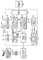
- a data accumulating system 16 as may be disposed at a remote station and coupled to a master station (data terminal) 12 via telephone lines or other conventional communication link 13, such as power lines or radio.
- the communication link 13 is connected to a data coupler 14 and an answer modem 18; the answer modem 18 is a frequency shift keying (FSK) modulator/ demodulator as are well known in the art, e.g. a Bell 103 modem.
- the data accumulating system 16 is designed to read from one to a given number "n", e.g. 10, of data sources in the illustrative form of meters 30a to 30n.
- the meters 30 may be gas, water, electric or any other device that outputs pulses that may be counted. It is further contemplated that the data sources may take the form of any analog data source and that this data accumulating system 16 may include suitable analog to digital converters such as voltage control oscillators that convert such analog inputs to digital outputs in the form of trains of pulses whose number is proportional to the data being measured. Each meter 30 is associated with a respective one of a plurality of counters 24a to 24n that accumulates pulses and the system has an ability to receive a variable number of such meters 30n, less than or equal to "n".
- the data accumulating system 16 permits a centrally disposed operator to access via the master station 12 the data accumulating system 16 and to obtain the accumulated outputs of each of its counters 24a to 24n.
- An initializing or counter preset unit 34 is used with each data accumulating system 16 to preset selectivity via a preset MUX 32 the counters 24a to 24n, with an initial value or count.
- the preset MUX 32 permits the counter preset unit 34 to selectively monitor the contents of a particular counter 30 and if required, apply an initial value of count to a particular counter, e.g., the preset MUX 32 selectively applies a count, for example, to the first counter 24a.
- the data accumulating system 16 has the capability of detecting a given number of alarm signals AL1 and AL2 ⁇ applied via an interface 22 to a microprocessor system 20.
- the data accumulating system 16 is provided with a power supply 36 coupled to an ordinary 120 V.A.C., 60 Hz line.
- a battery backup supply circuit 38 is connected to each of the counters 24a to 24n making them in effect non-volatile upon failure of the primary power supply and also to energize a time of day (TOD) clock circuit 80 (included generally within the microprocessor system 20 as shown in Figure 1) that continues to provide the correct time of day even if the primary power source should fail, as shown in detail by Figure 3.
- TOD time of day
- each data accumulatin system 16 has a storage element 26, which is a security access code that permits access to the system 16 only by an interrogation message from the master station which contains the corresponding code.
- the data accumulating, system 16 has the capability of accumulating pulses from any number of meters 30 up to "n" for a programmable period of time, whereby data, i.e. a number of pulses per given time period as indicative of the metered utility, may be determined and transmitted back to the master station 12.
- the operator at the master station 12 may transmit a call to a selected data accumulating system 16 to set or reset the time period.
- the TOD clock circuit 80 generates and stores a correct time of day indication that will not be lost upon failure of the primary power source.
- an indication of the correct time is transferred from the TOD clock circuit of Figure 3 to be stored within a volatile, primary memory in the form of a RAM 70 included generally within the microprocessor system 20 of Figure 1 and as shown in detail by Figure 2B.
- the TOD indication as stored in the RAM 70 is used in the calculations of data rate, e.g. the rate of water consumption, as will be explained in greater detail later. It is further contemplated that the TOD indication may be used to identify the time of occurance of a particular event, e.g. to determine the use of electricity at a particular time of day whereby electricity used during peak demand times may be billed at a higher rate.
- the time of day indication may be used to provide a history of data occurances, typically known as "histograms", whereby a utility used may be recorded in selected intervals, over an extended period of time. For example, water usage for each hour of the last day may be accumulated to provide a statistical record thereof.
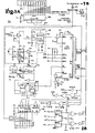
- the microprocessor system 20 as shown in detail by Figures 2A and 2B, is programmed (as will be explained in detail later) to determine the number of meters 30 that are presently coupled to the data accumulating system 16 and to perform calculations and data retrieving procedures on only those meters that are actually coupled.
- the microprocessor system 20 as generally shown in Figure 1 is shown in detailed circuit form in Figures 2A and 2B.
- the microprocessor system 20 includes a processor 40 illustratively taking the form of a model 6502 CPU manufactured by the assignee of this invention, and an interface logic unit known as a VIA 50 illustratively taking the form of a model 6522 as manufactured by the assignee of this invention.
- a non-maskable interrupt is derived from the answer modem 18 as shown in Figure 1 upon the reception of an interrogation call from the master station 12 to initiate the processing of the interrogation signal transmitted by the master station 12, whereby only those counters 24 coupled to meters are accessed to determine the pulse counts accumulated from the coupled meters 30 to retransmit a message via the answer modem 18 and the data coupler 14 to the master station 12.
- a computer clock 72 comprises a crystal oscillator 84 whose output is applied via flip-flops 78 and 82, which divide the 4MHZ clock signal down to 1MHZ, to be applied to an input Qin of the processor 40.
- An address bus 42 connects the processor outputs AO to A15 to the VIA 50 and to each of a programmable read-only-memory (PROM) 60 and of an addressable memory taking the form of the.RAM'S 70a and 70b.
- a data bus 44 is connected to the processor outputs DO to D7 of the PROM 60 and to the outputs DO to D3 of the RAM 70a, to the outputs D4 to D7 of the RAM 70b to the inputs D0 to D7 of the processor 40, and to the DO to D7 outputs of the VIA 50.
- the address bus 42 is also applied to the counters 24 via a counter select decoder in the form of a MUX 86 illustratively taking the form of a model 74LS145 as manufactured by SIGNETICS.
- the MUX 86 responds to the address signals derived from the processor 40, to select one of the counters 24.
- the particular digit of the selected counter is selected by address signals applied via a counter digit decoder 76 taking the form of a model 74LS156 of SIGNETICS. which in turn applies its signals via a bus 25 to the counters 24.
- each of the counter select bus 23 and .the counter digit select bus 25 is connected to the counters 24, whereas a counter data bus 21 applies the count of an addressed counter 24 to the inputs PA4 to PA7 of the VIA 50.
- outputs of selected alarm circuits are applied via an interface circuit 88 comprised of optical isolators, whose outputs are in turn applied as shown in Figure 2B to inputs CB1 and CB2 of the VIA 50.
- the time of day circuit 80 is connected to the microprocessor 40 by way of the inputs CA1, CA2 and PA3 of the VIA 50, as illustrated in Figure 2B.
- a suitably formatted data signal is transmitted from the output PBO as shown in Figure 2B by bus 27 to the answer modem 18, which then modulates the data signal and transmits it to the master station 12.
- the initialization routine calls the-program as shown in Figures 5A and 5B to transfer after power restoration a correct time of day indication to the RAM 70.
- the circuit 74 includes a first dual timer 71 that is connected to resistor R5 and capacitor C17 to establish a period after the initial application or restoration of the primary voltage Vcc during which the primary voltage stabilizes, before the CPU 40 begins to execute its programs and in particular, calls its initialization program.
- the capacitor C17 Upon the application of the primary voltage Vcc, the capacitor C17 is charged through resistor R5, until the charging voltage equals the triggering voltage of the timer 71, at which time the timer output goes high, whereby the output of the circuit 74 as derived from a second timer 75 goes low to reset the CPU 40.
- the circuit 74 further includes a watchdog timing circuit including the second timer 75, which is connected as an oscillator to provide an output every 2 seconds, unless otherwise reset or defeated.
- the CPU 40 will generate from its via 50 a reset signal TMRRST if the CPU 40 is operating correctly.
- the primary voltage Vcc may go low, thus disrupting the normal execution of the programs by the CPU 40; if this should happen, the reset signal TMRRST will not be generated.
- the reset signal TMRRST will be applied every 50ms to the base of transistor Q1 rendering it conductive, whereby the capacitor C21 will be discharged to ground.
- capacitor C21 will charge to trigger the timer 75 thus driving the RES input low to reset the operation of the CPU 40.
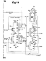
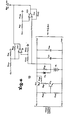
- the time of day circuit 80 is shown in the detailed circuit diagram of Figure 3 as including a clock comprised of circuit elements C48, C49, C50, R49 and R50, and a crystal oscillator 100 whose output is applied to the 01 input of a divider 102, illustratively taking the form of a model CD4060D as manufactured by RCA.
- An output is taken from the counter 102 and applied via a NOR gate 103 to the input of a secondary memory in the form of a counter 104 illustratively taking the form of a model MC14521B as manufactured by MOTOROLA.
- an auxiliary battery Bl (as shown is Figure 7) applies a voltage Vcc' to the time of day clock circuit 80.
- Figure 3 clearly shows that the auxiliary voltage Vcc' is applied to the elements of the time of day circuit 80, whereas the microprocessor system as shown in Figures 2A and 2B is energized by the primary power source Vcc.
- the primary power source in the typical form of a 60Hz signal energizes the power supply 36 which provides a voltage Vcc to the elements of the microprocessor system 20, as well as to the secondary power source in the form of the battery backup supply 38.
- the backup supply 38 continues to apply the voltage Vcc' to energize the time of day circuit 80, whereby a clock signal continues to be applied to the counter 104 and accumulated therein until the primary power source is restored.
- the count stored within the secondary memory i.e. the counter 104
- an overflow output Q19 is derived from the counter 104 and is applied via an exclusive OR gate 106 to one input of an exclusive OR gate 107, whereas the other input of the exclusive OR gate 107 is derived from a delay circuit primarily comprised of resistor R52 and capacitor C51.
- the capacitor C51 is charged to a predetermined level until the exlusive OR gate- 107 resets the counter 104 back to 0.
- the output of the exclusive OR gate 106 is applied via the AND gate 108 and OR gate 110 to the CA2 input of the VIA 50 as shown in Figure 2B.
- the other input to the AND gate 108 is the primary voltage Vcc, thus enabling the AND gate 108 only in the presence of the primary voltage Vcc.
- a high frequency clock signal is applied from the PA3 output of the VIA 50 via the exclusive OR gate 103 to the IN input of the counter 104.
- the output of the divider 102 is also applied via an exclusive OR gate 112, an AND gate 114 and an OR gate 116 to the input CA1 of the VIA 50.
- the primary voltage Vcc is removed from selected of the circuit elements of the time of day circuit 80 as shown in Figure 3, and in particular, from the inputs of the AND gates 108 and 114, thus disabling the AND gates 108 and 114.
- the current drain imposed upon the secondary power source and in particular the battery B1 as shown in Figure 6 is reduced, i.e. the load as would be imposed by the via 50 is switched out of circuit with the battery B1 by disabling the AND gates 108 and 114, which act as switch means.
- the clock output of the divider 102 is also blocked by the disabled AND gate 114.
- the primary voltage Vcc is reapplied to enable the AND gates 114 and 108.
- the clock output of the divider 102 is permitted to pass via the enabled AND gate 114 to the CA1 input of the VIA 50, whereby the count accumulated in the secondary memory taking the form of the counter 104 is transferred via an enabled AND gate 108, the NOR gate 110, the input CA2 of the VIA 50 to be stored within the primary memory, i.e. the RAM 70.
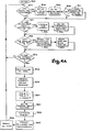
- FIG. 4A shows a high-level flow diagram of a monitor routine that is executed by the microprocessor system 20 to collect and process meter data.
- step 302 determines whether an interrogation call is received from a local hookup and in particular looks to see if a start bit as would appear at the PB7 input of the VIA 50 as shown in Figure 2B,.is provided.
- Step 312 determines whether the counter preset unit or initializer 34 is connected. If yes, step 314 disables the answer modem 18, and routine 316 is run to enter the initializing count in the selected counter 24. If no, step 318 determines if the time of day equals 2400 HRS, indicated by the 2400-HR flag being set.
- Steps 320 and 322 respectively resets the time indication in counter 104 to "0000 HRS” and resets the 2400 HR test flag to "0".
- Step 324 checks to determine whether a given demand interval (DI) has timed out and if not, the monitor rountines loops back to step 302. If yes, step 326 provides for a reprogramming or reinitializing of the demand interval.
- Step 328 is a part of the process whereby the counts, which are stored within the counters 24 are read to calculate the counts received within a given interval.
- a series of tables, 1, 2 and 3 are established within the RAM 70, the first table indicative of the current data accumulating, Table 2 indicative of the previous data accumulatinq and Table 3 being the difference or that measured quantity, e.g. flow, that has occurred in the most recent time interval.
- Step 330 calculates the difference between the counts of tables 1 and 2 to provide a value of the counts received in a given interval as placed in Table 3.
- Step 332 is used to determine a maximum peak interval, wherein a fourth, maximum count table is used for receiving and comparing the current interval count as stored in Table 3 with the peak count stored in Table 4. If the count stored in Table 3 is greater than that in Table 4, Table 4 is updated with the new peak count.
- a fifth table is set up comprising an array of storage locations for receiving the meter or data readings from table 3 for each of the previous time intervals. More specifically, as utility consumed during the last interval is stored in table 3, that data is also transferred to the next location of the fifth table.
- the number of locations of the table 5 is only limited by the size of the RAM 70.
- a sequence of data or meter readings for each interval is stored in the array of table 5. For example, meter readings could be taken each hour and the difference therebetween stored in an array of 24 storage locations within the RAM 70, whereby an indication of the utility use for a complete day may be provided.
- Step 334 formats the data as stored in Tables 2, 3, 4 and 5 for transmission via the answer modem 18 and the data coupler 14 to the master station 12.
- the answer mode control routine is initiated by the receipt of a non-maskable interrupt signal as derived from the answer modem 18 upon the receipt of an interrogation call from the master station 12.
- the routine NMISRV may be entered as in the local hookup step 310 of the monitor routine.
- step 342 the status and working registers of the microprocessor are saved in a stack formed in the RAM 70.
- step 344 determines whether the local flag is set indicating that the data accumulating system 16 is directly coupled to a data terminal or alternatively, whether the data accumulating system 16 is coupled via the data coupler 14 to telephone lines 13.
- step 346 determines whether the CTS signal has gone low as would be derived from the modem 18 and applied to the VIA 50, indicating that a handshaking relationship has been established between the modem 18 of the data accumulating system 16 and the master station 12. On the other hand, if an interrogation call is transmitted from the master station 12 and a handshaking relationship has not been established therebetween, i.e. step 346 decides no, the timing of a period Tl of twelve seconds is initiated in step 354. Next, in step 356, the counters 24 are accessed to determine the current meter readings. Thereafter, step 358 again determines whether the CTS signal has gone low and if not, step 360 determines whether the Tl delay period has timed out.
- routine will loop between steps 358 and 360 until either the CTS signal goes low or the time delay period expires, at which time the routine exits through step 366 to "hang up" the phone and to effect a return from interrupt (RTI) to the MONITR routine of Figure 4A.
- the time delay Tl will time out, if there was an illegal call and the calling station could not provide the required handshaking signals, or the transmission lines were defective. If either of steps 346 or 358 determines that the CTS signal has gone low, there is an indication, that the modem 18 and its data accumulating system 16 is ready to transmit data and that the master station 12 is ready to receive the transmitted data.
- step 362 starts the transmission sequence wherein each bit of the data message as formulated in step 334 is transferred at a rate of 300 bits per second to the modem 18.
- a variable table is formed in the RAM 70 to permit the forming of a heading, the framing of the requested data and appropriate carriage returns whereby the printout devices provided at the master station 12 may be operated in a manner to present data in a desired display format.
- Step 364 determines whether transmission has been completed and if no, returns to an intermediate step of the transmission process. If yes, step 366 shuts down the answer modem 18 and in effect hangs up the phone.
- step 368 determines whether the local flag was set and if not, step 372 recovers the data and return addresses stored in the RAM stack before returning to look for new interrupts. If the local flag was set, the return addresses and input message as stored in the RAM stack are recovered and a return to subroutine (RTS) is effected in step 370.
- RTS return to subroutine
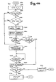
- FIG. 5A and 5B The program as shown in Figures 5A and 5B is stored within the PROM 60 to be executed by the processor 40 as shown in Figures 2A and 2B.
- Figure 3 shows the TOD clock circuit 80, whose elements are energized in the case of power outages by the auxiliary power supply which continues to supply a voltage Vcc' to the elements of circuit 80 even in the absence of Vcc.
- the crystal 100 provides a clock signal to be divided by divider 102 before being applied to the counter 104, particularly noting that the counter 104 is energized by the voltage Vcc'.
- the overflow terminal Q19 of the counter 104 is applied via NOR gate 110 to the CA2 input of the VIA 50 as shown in Figure 2B.
- Step 5A upon initialization or the restoration of primary power source to the data accumulation system 16, the power-on reset and watchdog timing circuit 74 drives low the RES input of the CPU 40, thereby resetting the CPU 40 and calling an initialization routine.
- a call is made to the program as shown in Figures 5A and 5B and this program is entered in step 400.
- Step 402 sets into a RAM location a maximum number of counts corresponding to 36 hours, 24 minutes and 32 seconds, which is the maximum storage time of the counter 104.
- step 404 a software routine is run to generate and apply a very high frequency clock signal from the PA3 output of the VIA 50 through the NOR gate 103 to the counter 104 to increment the count therein corresponding to the correct time of day, until counter 104 overflows to provide from its output Q19 a signal or flag via the NOR gates 106 and 110, and the enabled AND gate 108 to the CA2 input of VIA 50, thereby terminating the generation by the software of the high frequency clock signal.
- Step 406 checks to see whether the CA2 interrupt signal has occurred and if not, step 407 decrements by one second the maximum count of 36 hours, 24 minutes and 32 seconds as stored in the time register of RAM 70.
- the maximum amount of time stored in RAM 70 will be decremented until the interrupt at CA2 occurs, whereby in effect the correct time as stored in the counter 104 has been transferred from the counter 104 of the time of day circuit 80 to the time register in RAM 70.
- a further check is made after the interrupt has occurred in steps 408 and 410 to determine whether the time register within RAM 70 is greater than 24 hours and if yes, to subtract 24 hours from that value.
- the time indication in the time register of RAM 70 is the correct time of day.
- steps 418 to 426 effect a time or count transfer in a similar manner to steps 404, 406 and 407, since counter 104 is automatically reset to "0000" (zero) when the overflow interrupt occurs.
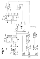
- FIG 6 is a detailed circuit diagram of the battery backup supply 38, as shown generally in Figure 1, for continuing to apply the secondary voltage Vcc' to the counters 24, as well as to the time of day circuit 80 shown in Figure 3, even after primary power failure.
- the regulated supply 36 is connected to conventional AC power line to supply a primary voltage Vcc to the input of the battery backup supply 38 across resistors R35 and R36, whereby a transistor Q3 is biased conductive, thus in turn biasing transistor Q2 conductive.
- a diode D2 is backbiased thus preventing the secondary power source in the form of battery Bl from applying its voltage to the counters 24 and to the time of day circuit 80.
- the voltage Vcc is applied, the battery is being charged through tickle resistor R39.
- the transistor Q2 is conductive and applies a voltage Vcc' slightly less the primary voltage Vcc to the TOD circuit 80.
- the output of the battery. or auxiliary power source Bl is also applied to a first operational amplifier 122, which compares Vcc l with the primary voltage Vcc and if less than or more negative than a predetermined value generates a warning signal in the form of the BATFLG flag that is applied to the VIA 50 as shown in Figure 2B.
- the secondary voltage Vcc' is applied to a second operational amplifier 120 which compares the secondary voltage Vcc' to the primary voltage Vcc and if greater or more positive by a predetermined value also sets the BATFLG flag; in this fashion, the microprocessor system 20 may provide a manifestation to the operator of the master station 12 indicative of the failure of the secondary power source, i.e., the battery Bl.
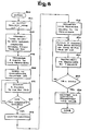
- FIG 7 is a flow diagram of a routine as stored in the PROM 60 as shown above in Figure 2B for effecting to scan of the outputs of the meters 30 to determine whether they are coupled to the counter data bus 21 as shown in Figures 2A and 2B.
- the meter scanning routine determines how many meters 30 are connected to the counter data bus 21 and to store that information in RAM 70, whereby upon receiving an interrogation message from the master station 12, the microprocessor system 20 access only those counters 24 associated with meters 30 that are actually coupled to the data accumulating system 16, ignoring those meter inputs to the data accumulating system 16 that are unconnected to any meter 30.
- the bus coupled to the counters 24 includes the counter select bus 23, the counter digit select bus 25 and the counter data bus 21; such buses are configured to receive up to the given number "n" of meters 24.
- a selected number of meter 30 equal to or less than "n" may be coupled to the data accumulating system 16.
- step 702 sets a TEMP register within the RAM 70 to zero.
- the TEMP register stores a count indicative of the number of meters 30 that are connected to the counter bus 27.
- step 702 sets an index register X to a predetermined value, e.g. 10; the index register is a location within the RAM 70 wherein the index to the starting address of the counters 24 to be addressed via counter select bus 23, is stored.
- step 704 the counter 24 whose base address is indexed by register X is addressed. In the initial instance, the counter 24 having the base address indexed by 10, is addressed first and it is determined whether its output as appears on the counter data bus 21 equals "F," which is an illegal digit "1111,” as by step 706.
- step 708 determines that a counter 24 is connected to the counter bus 27, and thereafter in step 710, the TEMP register is incremented, whereas the index register X is decremented in step 712.
- step 714 determines whether the counter address as stored in the index register X is 0 and if not, recycles to step 704, whereby the process is repeated until the counter address as stored in the index register X is decremented to 0.
- the address within the index registered X has been decremented to 0
- the first of the two scans has been completed and the program continues on to step 716, to test whether the contents of the TEMP register equals to 0 and if so as decided by step 718, a "no counters" flag is set in step 720.
- the second scan begins by setting the index register X to 0 and an index register Y to 0.
- the index register Y is a location in RAM 70 where the number of meters 30 as coupled to the counter bus 27 is stored noting that the TEMP register as referred to above is a temporary register that is incremented during the first scan to that number of meters 30 as detected during the first scan and is incremented during the first scan to a number indicative of the number of connected meters 30, whereas in the second scan, the TEMP register is decremented until its value equals 0.
- step 724 the count as currently stored in the index register X is addressed via the counter select bus 25 and its output is compared with the invalid digit "F" and if unequal, a notation is made in step 730 that its contents are valid and a meter 30 is coupled to the bus 27.
- step 732 the TEMP register is decremented and in step 734, the contents of the TEMP register is compared to 0, and if not equal to 0, the second scan is continued in step 728, which increments by one each of the index registers X and Y, before returning to step 724, thus steps 722 to 734 are repeated until the TEMP register has been decremented to 0 indicating the completion of the second scan.
- the index register Y has been incremented a number of times corresponding to the number of meters 30 coupled to the counter bus 27.
- a manifestation is provided indicative that the value as stored in the index register Y is equal to the total number of meters 30 connected to the counter bus 27, which number is transferred in step 738 to the location CHNCTR within the RAM 70.
- the microprocessor system 20 may respond to an interrogation signal to access only those counters 24 actually coupled to meters 30 and to transmit back a message of a reduced length whose data is indicative of only the coupled meters 30.
- step 802 senses the presence of a command "7" that has been previously transmitted from the master station 12 to the data accumu- latina system 16. Beforehand, the operator at the master station 12 has sensed that the present manifestation of the time of day is incorrect and that a correction needs to be made.
- Step 804 waits for the operator, to enter the corrected time of day via the terminal at the master station 12.
- step 806 Upon receipt, step 806 transfers the four digits indicative of the correct time of day into a corresponding register of the RAM 70.
- step 808 initiates the synchronization and in particular the transfer of the correct time of day transmitted from the master station 12 to the counter 104.
- step 812 outputs two pulses via the terminal PA3 of the VIA 50 to increment the present count as stored in the counter 104 until it has overflowed as sensed by step 814.
- an overflow signal is developed at the output terminal Q19 and applied to the interrupt input CA2 of the VIA 50.
- step 816 indicates that the counter 104 has been reset storing digits "0000" therein.
- steps 812 and 814 cycle at a high rate to generate a series of pulses to the counter 104 until it has been reset. Thereafter in step 818, the value of the correct time of day manifestation as originally stored in a TOD reqister in RAM is transferred to a temporary register TR, also in the RAM 70. Step 820 thereafter causes two pulses, i.e. one second, of the time of day indication to be applied via the output terminal PA3 of the VIA 50 to the counter 104 and at the same time to decrement by step 822 the time of day manifestation as stored in the temporary registers TR.
- Step 824 determines whether the time of day manifestation as entered in the temporary register TR has been reduced to 0 and if not, cycles back through steps 820 and 822 until the correct value of the time of day as stored in the temporary register TR has been reduced to 0. At this time, it would be understood as indicated in step 826 that the correct value of the time of day has been entered into the counter 104.
- the interrupt request polling routine is entered when any of the interrupt conditions is present; in such case, the interrupt enable register within the VIA 50 has been set and the IRQ "output" of the VIA 50 is forced low.
- the IRQ "input" of the processor 40 is set low, the address of the interrupt request polling routine is pulled from the RROM 60 to enter the interrupt request polling routine 900.
- the routine 900 is entered in step 902 which saves the current address appearinq in the program counter and places it in a stack formed in the RAM 70.
- Step 904 saves the values as currently appearing in the accumulator or main operating register of the processor 40, as well as the values appearing in the X and Y index registers thereof, into the same stack of RAM 70, whereby upon completion of the routine 900, a return may be effected to the interrupted routine.
- the routine accesses an interrupt status register IFRREG within the VIA 50, that contains the status of the various interrupt conditions, as well as the interrupt enable register IERREG and loads the contents of these registers into the accumulator, whereby an anding operation is effected on the contents of these two reqisters.
- step 908 the routine 900 examines the accumulator register, wherein the previous contents of the IFRREG register has been stored, to determine whether an alarm has occurred. If yes, step 910 pushes (or saves) the contents of the accumulator into the aforementioned RAM stack, whereby the current interrupt condition is stored, thus enabling the detection of simultaneously occurring interrupt conditions.
- step 912 sets the appropriate alarm flags AL1 FLG or AL2 FLG before step 914 pulls (or restores) the last value from stack indicating the interrupt conditions back into the accumulator.
- step 916 determines whether the time of day (T.O.D.) interrupt has occurred and if yes, step 918 pushes (or saves) the contents of the IFRREG register into the RAM stack, before step 920 increments the time of day reoister in RAM and step 922 increments the demand interval (DI) timer counter formed in RAM 70. Thereafter, step 926 pulls the last value from the RAM stack and places it in the accumulator. Then, step 928 determines whether the timer T1 as found in the VIA 50 has timed out; if yes, step 930 pushes the value as found in the accumulator into the RAM stack, before step 932 resets the power-on reset and watchdog timer 74 as shown in Figure 2A.
- T.O.D. time of day
- step 934 increments another timer, i.e., the delay timer T1, which times out in various programs to provide a delay of a given period, before step 936 pulls the last value from the stack to be placed in the accumulator.
- step 938 determines whether counter 104 has overflowed to place a sianal upon the CA2 input of the VIA 50 and if yes, step 940 sets the CA2 FLG flag. Thereafter, step 942 pulls the values of A, X and Y from the RAM stack and places them into the accumulator, and X and Y index registers of the processor, before step 944 pulls the next value from the RAM stack indicative of the interrupted proqram counter and returns that value to the program counter.
Priority Applications (1)
| Application Number | Priority Date | Filing Date | Title |
|---|---|---|---|
| DE8383103711T DE3379554D1 (en) | 1982-06-10 | 1983-04-18 | Accumulator and transponder for time related data |
Applications Claiming Priority (2)
| Application Number | Priority Date | Filing Date | Title |
|---|---|---|---|
| US387531 | 1982-06-10 | ||
| US06/387,531 US4495596A (en) | 1982-06-10 | 1982-06-10 | Data accumulator and transponder with power back-up for time of day clock |
Related Child Applications (4)
| Application Number | Title | Priority Date | Filing Date |
|---|---|---|---|
| EP88100163A Division EP0308571A3 (de) | 1982-06-10 | 1983-04-18 | Datensammler und -Transponder |
| EP88100177A Division EP0305630A3 (de) | 1982-06-10 | 1983-04-18 | Datensammler und Transponder |
| EP88100163.0 Division-Into | 1988-01-08 | ||
| EP88100177.0 Division-Into | 1988-01-08 |
Publications (3)
| Publication Number | Publication Date |
|---|---|
| EP0101788A2 true EP0101788A2 (de) | 1984-03-07 |
| EP0101788A3 EP0101788A3 (en) | 1986-02-05 |
| EP0101788B1 EP0101788B1 (de) | 1989-04-05 |
Family
ID=23530275
Family Applications (2)
| Application Number | Title | Priority Date | Filing Date |
|---|---|---|---|
| EP83103711A Expired EP0101788B1 (de) | 1982-06-10 | 1983-04-18 | Speicher und Transponder für zeitgebundene Daten |
| EP88100163A Withdrawn EP0308571A3 (de) | 1982-06-10 | 1983-04-18 | Datensammler und -Transponder |
Family Applications After (1)
| Application Number | Title | Priority Date | Filing Date |
|---|---|---|---|
| EP88100163A Withdrawn EP0308571A3 (de) | 1982-06-10 | 1983-04-18 | Datensammler und -Transponder |
Country Status (9)
| Country | Link |
|---|---|
| US (1) | US4495596A (de) |
| EP (2) | EP0101788B1 (de) |
| JP (1) | JPS5920891A (de) |
| AU (3) | AU566129B2 (de) |
| BR (1) | BR8303075A (de) |
| CA (1) | CA1191922A (de) |
| DE (2) | DE308571T1 (de) |
| MX (1) | MX153946A (de) |
| NZ (1) | NZ203819A (de) |
Cited By (1)
| Publication number | Priority date | Publication date | Assignee | Title |
|---|---|---|---|---|
| US4850010A (en) * | 1985-11-25 | 1989-07-18 | Alcatel N.V. | Telemetry terminal |
Families Citing this family (29)
| Publication number | Priority date | Publication date | Assignee | Title |
|---|---|---|---|---|
| US4495596A (en) * | 1982-06-10 | 1985-01-22 | Rockwell International Corporation | Data accumulator and transponder with power back-up for time of day clock |
| US4833618A (en) * | 1986-02-20 | 1989-05-23 | Net Laboratories, Inc. | System for automatically reading utility meters from a remote location |
| US4866761A (en) * | 1986-06-20 | 1989-09-12 | Badger Meter, Inc. | Automatic meter reading system |
| US4878196A (en) * | 1986-12-18 | 1989-10-31 | Rose Frederick A | Communications management system |
| JPS63104735U (de) * | 1986-12-25 | 1988-07-07 | ||
| US4764952A (en) * | 1987-03-18 | 1988-08-16 | Feliu Horace G | Telecommunications device for reading power meters |
| AU3351989A (en) * | 1988-03-07 | 1989-10-05 | Telemetry Research Ii, Inc. | Method and apparatus for remote commodity transfer control and monitoring |
| FR2628588A1 (fr) * | 1988-03-14 | 1989-09-15 | Croquet Cie | Procede et systeme d'acquisition et de transmission d'informations sur l'audience de programmes televises |
| US5987058A (en) * | 1988-11-02 | 1999-11-16 | Axonn Corporation | Wireless alarm system |
| US5673252A (en) * | 1990-02-15 | 1997-09-30 | Itron, Inc. | Communications protocol for remote data generating stations |
| US5553094A (en) | 1990-02-15 | 1996-09-03 | Iris Systems, Inc. | Radio communication network for remote data generating stations |
| US5424808A (en) * | 1990-04-10 | 1995-06-13 | Minolta Camera Kabushiki Kaisha | Control apparatus for copying machine with improved communication function for centralized control unit |
| US5491535A (en) * | 1990-04-10 | 1996-02-13 | Minolta Camera Kabushiki Kaisha | Control appartus of copying machine with improved communication function for centralized control |
| US5125093A (en) * | 1990-08-14 | 1992-06-23 | Nexgen Microsystems | Interrupt control for multiprocessor computer system |
| JP3125505B2 (ja) * | 1993-02-16 | 2001-01-22 | ミノルタ株式会社 | 事務機管理システム |
| FR2701781B1 (fr) * | 1993-02-17 | 1995-03-31 | Neopost Ind | Machine à affranchir permettant un contrôle de la consommation journalière. |
| US5825648A (en) * | 1996-03-26 | 1998-10-20 | Casio Phonemate, Inc. | Backup system for a time of day clock in an electronic device |
| GB2315887B (en) * | 1996-07-27 | 2000-07-05 | Motorola Gmbh | Method and apparatus for re-programming memory device |
| US5994892A (en) * | 1996-07-31 | 1999-11-30 | Sacramento Municipal Utility District | Integrated circuit design automatic utility meter: apparatus & method |
| DE29713590U1 (de) * | 1997-07-30 | 1997-10-16 | Siemens Ag | Elektrischer Schaltkreis mit Zeitbildungsschaltkreis |
| WO1999013676A2 (en) * | 1997-09-12 | 1999-03-18 | Williams Wireless, Inc. | Wide area telemetry network |
| US5912514A (en) * | 1998-01-06 | 1999-06-15 | Smith Corona Corporation | Uninterruptible power supply unit |
| US7061398B2 (en) * | 1999-08-16 | 2006-06-13 | Bs&B Safety Systems Limited | Two-way wide area telemetry |
| MXPA01002994A (es) * | 2001-03-22 | 2004-07-30 | Fernando Milanes Garciamoreno | Sistema electronico y mecanico para dosificacion automatizada o discrecional del suministro de agua potable al nivel de la toma particular de cada usuario. |
| US8423302B2 (en) * | 2001-03-22 | 2013-04-16 | Fernando Milanes Garcia-Moreno | Electronic method and system for instant creation and storage of consumption histograms in drinkable water tapping points |
| US7050885B2 (en) * | 2002-02-15 | 2006-05-23 | Delphi Technologies, Inc. | Pulse count accumulator for pulse count motor control system |
| US7581154B2 (en) * | 2005-06-30 | 2009-08-25 | Intel Corporation | Method and apparatus to lower operating voltages for memory arrays using error correcting codes |
| JP6614749B2 (ja) * | 2013-03-20 | 2019-12-04 | 株式会社Fuji | 通信システム及び電子部品装着装置 |
| CN109470278B (zh) * | 2018-09-18 | 2022-03-04 | 中国电力科学研究院有限公司 | 一种确定计量设备的计量累计值处于增量为零状态的方法及系统 |
Citations (10)
| Publication number | Priority date | Publication date | Assignee | Title |
|---|---|---|---|---|
| GB1369939A (en) * | 1971-12-16 | 1974-10-09 | Int Standard Electric Corp | Transponder for telemetering system |
| US4086434A (en) * | 1976-09-07 | 1978-04-25 | Leo P. Christiansen | Remote condition reporting system |
| GB2017937A (en) * | 1978-03-31 | 1979-10-10 | Westinghouse Electric Corp | Auxiliary power supply and timer arrangement for time registering multifunctional electric energy meters |
| GB2018440A (en) * | 1978-03-31 | 1979-10-17 | Westinghouse Electric Corp | Programmable ac electric energy meter having rasiation responsive exernal data interface |
| EP0005842A1 (de) * | 1978-06-01 | 1979-12-12 | Universal Industrial Control Devices Ltd. | Mit hoher Geschwindigkeit arbeitender Zentralabtaster |
| US4218737A (en) * | 1977-08-30 | 1980-08-19 | The United States Of America As Represented By The Secretary Of The Army | Revenue metering system for power companies |
| US4301444A (en) * | 1979-10-19 | 1981-11-17 | Motorola, Inc. | Apparatus for detecting possible defeat of systems for remote metering of utilities |
| US4303850A (en) * | 1978-02-27 | 1981-12-01 | Rockwell International Corporation | Real time clock using computer and separate counting means |
| US4316246A (en) * | 1979-09-06 | 1982-02-16 | Honeywell Information Systems Inc. | Battery switching apparatus included within a timer adapter unit |
| CA1132219A (en) * | 1979-10-11 | 1982-09-21 | James R. Lumsden | Automatic meter reading transponder |
Family Cites Families (11)
| Publication number | Priority date | Publication date | Assignee | Title |
|---|---|---|---|---|
| US3747068A (en) * | 1971-11-04 | 1973-07-17 | Sangamo Electric Co | Remote meter reading system for kwh watthour meters and demand meters |
| US3894658A (en) * | 1974-06-20 | 1975-07-15 | Gen Atomic Co | Dispensing control system for fluids |
| US4213119A (en) * | 1976-04-29 | 1980-07-15 | Energy Optics, Inc. | Remote meter reading system providing demand readings and load control from conventional KWH meters |
| US4132981A (en) * | 1976-10-21 | 1979-01-02 | Rockwell International Corporation | Self-powered system for measuring and storing consumption of utility meter |
| US4276594A (en) * | 1978-01-27 | 1981-06-30 | Gould Inc. Modicon Division | Digital computer with multi-processor capability utilizing intelligent composite memory and input/output modules and method for performing the same |
| JPS5951793B2 (ja) * | 1978-06-08 | 1984-12-15 | 株式会社リコー | デ−タ収集方式 |
| JPS5569086A (en) * | 1978-11-17 | 1980-05-24 | Matsushita Electric Ind Co Ltd | Timer circuit |
| US4396844A (en) * | 1979-10-30 | 1983-08-02 | General Electric Company | Method and apparatus for controlling distributed electrical loads |
| US4280180A (en) * | 1979-10-30 | 1981-07-21 | Pitney Bowes Inc. | Electronic postage meter having field resettable control values |
| GB2088601B (en) * | 1980-11-24 | 1984-07-04 | Kennedy Stanley Paul | Recording energy use |
| US4495596A (en) * | 1982-06-10 | 1985-01-22 | Rockwell International Corporation | Data accumulator and transponder with power back-up for time of day clock |
-
1982
- 1982-06-10 US US06/387,531 patent/US4495596A/en not_active Expired - Fee Related
-
1983
- 1983-04-06 AU AU13205/83A patent/AU566129B2/en not_active Ceased
- 1983-04-07 NZ NZ203819A patent/NZ203819A/en unknown
- 1983-04-15 CA CA000425963A patent/CA1191922A/en not_active Expired
- 1983-04-18 EP EP83103711A patent/EP0101788B1/de not_active Expired
- 1983-04-18 DE DE198888100163T patent/DE308571T1/de active Pending
- 1983-04-18 DE DE198888100177T patent/DE305630T1/de active Pending
- 1983-04-18 EP EP88100163A patent/EP0308571A3/de not_active Withdrawn
- 1983-06-09 BR BR8303075A patent/BR8303075A/pt unknown
- 1983-06-09 JP JP58103522A patent/JPS5920891A/ja active Pending
- 1983-06-10 MX MX197618A patent/MX153946A/es unknown
-
1987
- 1987-01-09 AU AU67462/87A patent/AU589482B2/en not_active Ceased
- 1987-01-09 AU AU67461/87A patent/AU590041B2/en not_active Ceased
Patent Citations (10)
| Publication number | Priority date | Publication date | Assignee | Title |
|---|---|---|---|---|
| GB1369939A (en) * | 1971-12-16 | 1974-10-09 | Int Standard Electric Corp | Transponder for telemetering system |
| US4086434A (en) * | 1976-09-07 | 1978-04-25 | Leo P. Christiansen | Remote condition reporting system |
| US4218737A (en) * | 1977-08-30 | 1980-08-19 | The United States Of America As Represented By The Secretary Of The Army | Revenue metering system for power companies |
| US4303850A (en) * | 1978-02-27 | 1981-12-01 | Rockwell International Corporation | Real time clock using computer and separate counting means |
| GB2017937A (en) * | 1978-03-31 | 1979-10-10 | Westinghouse Electric Corp | Auxiliary power supply and timer arrangement for time registering multifunctional electric energy meters |
| GB2018440A (en) * | 1978-03-31 | 1979-10-17 | Westinghouse Electric Corp | Programmable ac electric energy meter having rasiation responsive exernal data interface |
| EP0005842A1 (de) * | 1978-06-01 | 1979-12-12 | Universal Industrial Control Devices Ltd. | Mit hoher Geschwindigkeit arbeitender Zentralabtaster |
| US4316246A (en) * | 1979-09-06 | 1982-02-16 | Honeywell Information Systems Inc. | Battery switching apparatus included within a timer adapter unit |
| CA1132219A (en) * | 1979-10-11 | 1982-09-21 | James R. Lumsden | Automatic meter reading transponder |
| US4301444A (en) * | 1979-10-19 | 1981-11-17 | Motorola, Inc. | Apparatus for detecting possible defeat of systems for remote metering of utilities |
Cited By (1)
| Publication number | Priority date | Publication date | Assignee | Title |
|---|---|---|---|---|
| US4850010A (en) * | 1985-11-25 | 1989-07-18 | Alcatel N.V. | Telemetry terminal |
Also Published As
| Publication number | Publication date |
|---|---|
| AU566129B2 (en) | 1987-10-08 |
| AU590041B2 (en) | 1989-10-26 |
| US4495596A (en) | 1985-01-22 |
| EP0308571A3 (de) | 1989-07-26 |
| AU589482B2 (en) | 1989-10-12 |
| EP0101788A3 (en) | 1986-02-05 |
| AU1320583A (en) | 1983-12-15 |
| AU6746287A (en) | 1987-04-30 |
| CA1191922A (en) | 1985-08-13 |
| DE305630T1 (de) | 1989-10-26 |
| JPS5920891A (ja) | 1984-02-02 |
| NZ203819A (en) | 1986-11-12 |
| EP0308571A2 (de) | 1989-03-29 |
| AU6746187A (en) | 1987-04-30 |
| MX153946A (es) | 1987-02-24 |
| EP0101788B1 (de) | 1989-04-05 |
| DE308571T1 (de) | 1989-10-26 |
| BR8303075A (pt) | 1984-01-31 |
Similar Documents
| Publication | Publication Date | Title |
|---|---|---|
| US4495596A (en) | Data accumulator and transponder with power back-up for time of day clock | |
| EP0311643B1 (de) | Selbsttätiges meterablesesystem | |
| US6115676A (en) | Methods and apparatus for performing load profile and load control | |
| KR100445226B1 (ko) | 분류형 데이터 구조를 이용한 원격 검침 시스템 | |
| EP0240761B1 (de) | Verfahren zur Gewinnung und Übertragung von Zählerdaten | |
| US4697182A (en) | Method of and system for accumulating verifiable energy demand data from remote electricity meters | |
| US4866761A (en) | Automatic meter reading system | |
| AU605468B2 (en) | Method of and system for accumulating verifiable energy demand data from remote electricity meters | |
| US5994892A (en) | Integrated circuit design automatic utility meter: apparatus & method | |
| CA1102424A (en) | Digital communication system for transmitting digital information between a central station and a number of remote stations | |
| NZ238245A (en) | Remote utility meter reading: encoded interrogation signal | |
| US5025470A (en) | Automatic meter reading system with malfunction protection | |
| US4621330A (en) | Programming system for programmable time registering electric energy meters | |
| GB2183852A (en) | Utility meter | |
| US4697180A (en) | System for accumulating verifiable energy demand data from remote electricity meters | |
| EP0248137B2 (de) | System zum Akkumulieren prüfbarer Energieverbrauchsdaten von fernen Elektrizitätsmessern | |
| EP0305630A2 (de) | Datensammler und Transponder | |
| US4697181A (en) | System for accumulating verifiable energy demand data from remote electricity meters | |
| KR100366402B1 (ko) | 각종 건물 계량기의 인터넷 검침방법 | |
| US4649569A (en) | Transceiver with auto frequency sense | |
| GB2284961A (en) | Automatic electricity meter reading system | |
| CA1062349A (en) | Remote automatic reading system | |
| KR20000034234A (ko) | 사용 요금 확인이 가능한 원격 검침 겸용무선 단말기 이용방법 | |
| JP2003122865A (ja) | 保守料金算出装置及び保守料金算出方法 | |
| GB2229834A (en) | Consumption meters and meter reading apparatus |
Legal Events
| Date | Code | Title | Description |
|---|---|---|---|
| PUAI | Public reference made under article 153(3) epc to a published international application that has entered the european phase |
Free format text: ORIGINAL CODE: 0009012 |
|
| AK | Designated contracting states |
Designated state(s): BE CH DE FR GB IT LI NL SE |
|
| PUAL | Search report despatched |
Free format text: ORIGINAL CODE: 0009013 |
|
| AK | Designated contracting states |
Designated state(s): BE CH DE FR GB IT LI NL SE |
|
| 17P | Request for examination filed |
Effective date: 19860523 |
|
| 17Q | First examination report despatched |
Effective date: 19870903 |
|
| GRAA | (expected) grant |
Free format text: ORIGINAL CODE: 0009210 |
|
| AK | Designated contracting states |
Kind code of ref document: B1 Designated state(s): BE CH DE FR GB IT LI NL SE |
|
| PGFP | Annual fee paid to national office [announced via postgrant information from national office to epo] |
Ref country code: FR Payment date: 19890414 Year of fee payment: 7 |
|
| PGFP | Annual fee paid to national office [announced via postgrant information from national office to epo] |
Ref country code: DE Payment date: 19890417 Year of fee payment: 7 |
|
| PGFP | Annual fee paid to national office [announced via postgrant information from national office to epo] |
Ref country code: CH Payment date: 19890418 Year of fee payment: 7 |
|
| PGFP | Annual fee paid to national office [announced via postgrant information from national office to epo] |
Ref country code: SE Payment date: 19890420 Year of fee payment: 7 |
|
| PGFP | Annual fee paid to national office [announced via postgrant information from national office to epo] |
Ref country code: BE Payment date: 19890421 Year of fee payment: 7 |
|
| ITTA | It: last paid annual fee | ||
| PGFP | Annual fee paid to national office [announced via postgrant information from national office to epo] |
Ref country code: NL Payment date: 19890430 Year of fee payment: 7 |
|
| REF | Corresponds to: |
Ref document number: 3379554 Country of ref document: DE Date of ref document: 19890511 |
|
| PGFP | Annual fee paid to national office [announced via postgrant information from national office to epo] |
Ref country code: GB Payment date: 19890531 Year of fee payment: 7 |
|
| ITF | It: translation for a ep patent filed |
Owner name: SOCIETA' ITALIANA BREVETTI S.P.A. |
|
| ET | Fr: translation filed | ||
| PLBE | No opposition filed within time limit |
Free format text: ORIGINAL CODE: 0009261 |
|
| STAA | Information on the status of an ep patent application or granted ep patent |
Free format text: STATUS: NO OPPOSITION FILED WITHIN TIME LIMIT |
|
| 26N | No opposition filed | ||
| PG25 | Lapsed in a contracting state [announced via postgrant information from national office to epo] |
Ref country code: GB Effective date: 19900418 |
|
| PG25 | Lapsed in a contracting state [announced via postgrant information from national office to epo] |
Ref country code: SE Effective date: 19900419 |
|
| PG25 | Lapsed in a contracting state [announced via postgrant information from national office to epo] |
Ref country code: LI Effective date: 19900430 Ref country code: CH Effective date: 19900430 Ref country code: BE Effective date: 19900430 |
|
| BERE | Be: lapsed |
Owner name: ROCKWELL INTERNATIONAL CORP. Effective date: 19900430 |
|
| PG25 | Lapsed in a contracting state [announced via postgrant information from national office to epo] |
Ref country code: NL Effective date: 19901101 |
|
| GBPC | Gb: european patent ceased through non-payment of renewal fee | ||
| NLV4 | Nl: lapsed or anulled due to non-payment of the annual fee | ||
| PG25 | Lapsed in a contracting state [announced via postgrant information from national office to epo] |
Ref country code: FR Effective date: 19901228 |
|
| REG | Reference to a national code |
Ref country code: CH Ref legal event code: PL |
|
| REG | Reference to a national code |
Ref country code: FR Ref legal event code: ST |
|
| PG25 | Lapsed in a contracting state [announced via postgrant information from national office to epo] |
Ref country code: DE Effective date: 19910403 |
|
| EUG | Se: european patent has lapsed |
Ref document number: 83103711.4 Effective date: 19910115 |