EP0099469A2 - System for the representation of text, graphics and symbols on monitor screens and/or with matrix printers - Google Patents
System for the representation of text, graphics and symbols on monitor screens and/or with matrix printers Download PDFInfo
- Publication number
- EP0099469A2 EP0099469A2 EP83105772A EP83105772A EP0099469A2 EP 0099469 A2 EP0099469 A2 EP 0099469A2 EP 83105772 A EP83105772 A EP 83105772A EP 83105772 A EP83105772 A EP 83105772A EP 0099469 A2 EP0099469 A2 EP 0099469A2
- Authority
- EP
- European Patent Office
- Prior art keywords
- memory
- point
- character
- data
- information
- Prior art date
- Legal status (The legal status is an assumption and is not a legal conclusion. Google has not performed a legal analysis and makes no representation as to the accuracy of the status listed.)
- Granted
Links
Images
Classifications
-
- G—PHYSICS
- G09—EDUCATION; CRYPTOGRAPHY; DISPLAY; ADVERTISING; SEALS
- G09G—ARRANGEMENTS OR CIRCUITS FOR CONTROL OF INDICATING DEVICES USING STATIC MEANS TO PRESENT VARIABLE INFORMATION
- G09G5/00—Control arrangements or circuits for visual indicators common to cathode-ray tube indicators and other visual indicators
- G09G5/36—Control arrangements or circuits for visual indicators common to cathode-ray tube indicators and other visual indicators characterised by the display of a graphic pattern, e.g. using an all-points-addressable [APA] memory
- G09G5/39—Control of the bit-mapped memory
-
- G—PHYSICS
- G06—COMPUTING; CALCULATING OR COUNTING
- G06F—ELECTRIC DIGITAL DATA PROCESSING
- G06F3/00—Input arrangements for transferring data to be processed into a form capable of being handled by the computer; Output arrangements for transferring data from processing unit to output unit, e.g. interface arrangements
- G06F3/14—Digital output to display device ; Cooperation and interconnection of the display device with other functional units
- G06F3/153—Digital output to display device ; Cooperation and interconnection of the display device with other functional units using cathode-ray tubes
-
- G—PHYSICS
- G06—COMPUTING; CALCULATING OR COUNTING
- G06K—GRAPHICAL DATA READING; PRESENTATION OF DATA; RECORD CARRIERS; HANDLING RECORD CARRIERS
- G06K15/00—Arrangements for producing a permanent visual presentation of the output data, e.g. computer output printers
-
- G—PHYSICS
- G09—EDUCATION; CRYPTOGRAPHY; DISPLAY; ADVERTISING; SEALS
- G09G—ARRANGEMENTS OR CIRCUITS FOR CONTROL OF INDICATING DEVICES USING STATIC MEANS TO PRESENT VARIABLE INFORMATION
- G09G5/00—Control arrangements or circuits for visual indicators common to cathode-ray tube indicators and other visual indicators
- G09G5/22—Control arrangements or circuits for visual indicators common to cathode-ray tube indicators and other visual indicators characterised by the display of characters or indicia using display control signals derived from coded signals representing the characters or indicia, e.g. with a character-code memory
- G09G5/30—Control of display attribute
-
- G—PHYSICS
- G06—COMPUTING; CALCULATING OR COUNTING
- G06K—GRAPHICAL DATA READING; PRESENTATION OF DATA; RECORD CARRIERS; HANDLING RECORD CARRIERS
- G06K2215/00—Arrangements for producing a permanent visual presentation of the output data
- G06K2215/0082—Architecture adapted for a particular function
- G06K2215/0091—Outputting only video data, e.g. Hard copy of CRT display
Definitions
- the invention relates to a method and a circuit arrangement for the visual representation of texts, graphics and symbols on screens of monitors and / or by means of point-controlled printers according to the preamble of patent claim 1.
- the English system Prestel assigns an address in the refresh memory to every location on the screen.
- the content of the memory address is decoded in a read-only memory (ROM) and provides the character resolution on the screen or interprets an attribute (display feature such as color, flashing) in a space between words or characters, which is then used for the rest of the row to be displayed until further notice applies.
- ROM read-only memory
- the transmission code is practically stored in the frame buffer. Due to the system, only a small character set (94 characters) and the restriction to only one attribute in the space is possible. This keeps the memory at 1 k x 7 bit small, but the scope for displaying it is very limited.
- the attribute is assigned to a cursor and jumps with the cursor regardless of the rows, therefore also called parallel or cursor-oriented.
- such attributes are necessary to enable different forms of representation. These range from the background colors, display colors, character size to the blinking of individual characters. The other two systems allow further resolved representations.
- composition method With the introduction of the standardization known under the term "composition method" with the possibility of switching multiple attributes without a space, the memory content of the image repetition memory is no longer easily readable for printers and cassette recorders, since terminal-specific code compression from the transfer code to the image repetition memory must take place.
- a solution for a screen text decoder is described in the cited reference.
- the memory is then divided into two due to the low degree of utilization of the image repetition memory capacity of more than 1 kx 32 bit.
- a 1 kx 8 bit memory serves as a refresh memory in which each address is assigned to a location on the screen.
- a second memory is allocated to the first when in use, ie dynamic allocation of memory spaces takes place.
- the first part of the memory contains 7 bits for the display of the characters and 1 bit as a pointer (pointer), which indicates whether additional information is required at this point on the screen, e.g. changes in attributes or another set of characters C 6 C 5 C 4 C 3 C 2 C 1 C o Z.
- the second part of the memory contains only the additional information.
- the screen text decoder has a decoding device which responds to digital character encodings and outputs coded bytes which can be used by the display device to display selected points of a dot matrix.
- the arrangement includes: a page RAM or a character ROM for comparing the characters stored in the character RAM.
- a control code is assigned to each character, the group of digital codes of a character being represented as such and relating to the corresponding points in the matrix. It is not possible to call up the individual points and to change the attributes of the individual points.
- D is a character-oriented system as well, ie all yak Congressen.Digitalcodtechniken of a character to be displayed together, the system is also limited to a certain number of characters that can be stored.
- the invention has for its object, while avoiding the disadvantages of known systems to create a screen text decoder with high performance and high flexibility, without using a pointer-bit link between character and attribute memory, whereby it should be ensured that each individual point of a character on the screen can be controlled, that each of these points can be assigned separate information (e.g. double the font size) and that a scrolling process is possible without having to save the entire page again and thus the computing effort (time) for the Reorganization of the stored data is reduced.
- the screen texts, as offered by the new communication services should not only be displayed on the screen, but also by means of point-controlled matrix printers on visible record carriers such as paper, film and the like, both in connection with a monitor and regardless of this.
- a screen text decoder differs from known screen text decoders in that it enables the point-oriented storage of each individual point of a character in accordance with attributes and sub-attributes or direct color assignments, the information stored in the corresponding read / write memory (RAM) read out point by point and given directly or via a color memory, which stores the information related to each individual point, to a matrix circuit for display on a display, a monitor of a monitor or a color television receiver.
- RAM read / write memory
- a character-based implementation for example using a character generator or writing the characters in blocks, does not take place but only the point-by-point representation of each line.
- the on-screen text decoder enables a variety of display forms of the characters due to the punctual storage of the character information and the associated character block attributes. This leads to the following ergonomic advantages: higher frame rate (e.g. flicker-free 75 Hz), texts with a higher number of lines per character, 20 lines of text per image, 960 different characters that can be loaded remotely (DRCS mark, NTZ 1981, number 11, pages 779 and 780) regardless of the mode , ie a complete image format with DRCS resolution can be displayed, the transmission takes place with multi-page pages and the use of a light pen, e.g. for editing. DRCS characters, positioning 25 lines of text for additional information, e.g. alternating labeling of a row of keys or specification for the light pen.
- higher frame rate e.g. flicker-free 75 Hz
- texts with a higher number of lines per character 20 lines of text per image
- 960 different characters that can be loaded remotely 960 different characters that can be loaded remotely (DRCS mark, NTZ 1981,
- the screen text decoder can be implemented with highly integrated standard components (microcomputer ROMS, static and dynamic RAMS, CRT controller).
- the point-oriented structure of the display area ensures a high level of system flexibility.
- the intended CRT controller can be programmed on different display formats.
- the ROM area for entering the individual characters can be expanded up to 64 kB for program expansion.
- the RAM area provided as page memory can also be expanded to 64 kB for multi-page storage.
- the number of pages stored depends on their complexity. 2K x 8 organization storage. can also be used, non-volatile memory and read-only memory.
- a particular economic advantage over a character-oriented concept is that the point-oriented system according to the invention can be implemented with only about 70 integrated circuits compared to 300.
- the core cell of the screen text decoder is a dynamic random access memory (RAM), which is point-oriented, i.e. each memory cell is assigned a point with the associated color for display on the screen.
- RAM dynamic random access memory
- the parallel addressed attribute memory is provided, which is expediently constructed from static RAMS for reasons of capacity. Stand there. Information that applies to a complete drawing space, such as Color of the background, different flashing frequencies, differentiation of the RCS mode. The system would be too slow for playback using the scrolling method, in which individual rows of characters are hidden and others are inscribed. This is remedied by the additional addressing memory according to the invention, which is constructed from a static RAM, because when the arrival of new data the entire memory area of the dynamic RAM does not have to be changed.
- the addresses to be changed are only changed in the addressing memory.
- the sequence is then read out from the point memory in accordance with the changed address via the addressing memory.
- the data of the addressing memory form the addresses of the attribute memory and the subaddresses of the point memory connected via an address logic. Addressing via an address logic is required if the memories cannot be addressed in parallel but only in series.
- the memories are each addressed during the vertical blanking time via an address multiplexer.
- the memories to be controlled are expediently activated via a chip selector. If suitable software is selected and the hardware is adapted, addressing can also take place without prior memory selection.
- the microprocessor outputs the character-related addresses and attribute data determined using known programs and using registered programs. These reach the corresponding memories via an address bus and a data bus and are stored at the addressed locations. According to the program written, the microprocessor also processes the text signals arriving from a modem and stores them in the assigned data memory (page memory).
- the control is triggered by commands entered from a remote control or a keyboard.
- the point-related data are read out from the point memory and the attribute information from the attribute memory is carried out by means of a CRT controller, which forms the control device.
- CRT controllers e.g. MC 6845 from Motorola, described in the Motorola data book “Semiconductors, Microcomputer Components", 1979, p. 193 and ff.
- the CRT controller is supplied by a clock frequency of 1 MHz at normal television frequencies, ie 50 Hz frame rate and normal number of lines .
- Via a data bus he can access certain display formats. be programmed.
- the format usually used consists of 40 characters per line and 24 lines of text per image. However, a different size of the V and H blanking gaps and their assignment to the image display can also be programmed.
- the invention is in two with respect to screen text printing. Variants available. On the one hand, it allows the connection of a printer to a screen text decoder, which works according to the method of claim 1.
- the display speed on a screen is determined by the deflection speed of the scanning electron beam. Conventional matrix printers cannot follow this speed.
- a data memory is therefore to be interposed in a further embodiment of the invention according to claim 3 in order to have the read-in data read out and printed out by the printer control device regardless of the writing speed.
- the data memory used here acts as a character buffer in which the characters are stored line-by-line.
- the data is expediently read out via a point shift register switched by the computer control device, but which can also be clocked by a character display processor.
- the readout speed is adapted to the printing speed of the printer or takes place in the writing speed of the electron beam, a character buffer being provided for temporarily storing the characters.
- the character buffer is read out by the printer controller at print speed.
- the invention offers a further advantage, which is that there is a common interface for printer and screen text display. This makes it possible either to combine the computer control device, the page and character memory with a printer, or to connect the word processing circuits to the printer for display on a screen.
- other peripheral devices that process the incoming signals can also be connected to the same interface, provided they process the point-oriented data.
- a teletext decoder and the printer with all S cibilmalen for carrying out the method according to the invention are explained below with reference to the embodiment illustrated in the block diagrams FIG. 1 to Figure 3 embodiments.
- the screen text decoder consists of a microprocessor 1, which evaluates the received text signals, operating function signals and input and control values and is programmed accordingly for the link control.
- a read memory 2 (ROM) serves as the program memory for the microprocessor.
- a read / write memory 3 which can be expanded to a maximum of 64 kB and in which the received text pages are stored is used as the data memory. Since the microprocessor 1 outputs both the addresses and the character-related data via one and the same outputs for reasons of capacity, an address buffer 23 is provided, in which the addresses are buffered so that they can be read out.
- a chip selector 4 is also provided in front of the interface A-B, which activates the memories to be used for address breakdown.
- the microprocessor 1 is clocked via its input 1.1 with a clock frequency, for example 12 MHz.
- the one for the Processor necessary sub-frequencies are generated by own division.
- the inputs 1.2 and the outputs 1.3 and 1.4 are connected to a modem that is connected to the telephone line and is received via the coded signals or is output to the computer center in dialog communication.
- Input 1.5 can be connected to a keyboard, which is not shown for the sake of simplicity, by means of which the programs can be written or the corresponding information can be entered individually for display on the screen.
- Input 1.6 is provided as an infrared remote control input. This is used to enter the control functions from the remote control, for example the playback command for teletext signals transmitted in the vertical blanking intervals of the television signal, switching to on-screen text reception, television reception, etc.
- the interface A-B is connected to the interface A'-B '.
- the pages first stored in the RAM 3 by the microprocessor 1 are read out again for reception for the purpose of display and the character content is compared with the character set contained in the program memory 2.
- the microprocessor 1 determines which structure the character has and which attribute is to be assigned to it.
- the corresponding data is stored character-wise character-by-character and point-by-line in the corresponding memories 6 and 8 described later.
- the storing of the characters associated data as well as the addressing and readdressing done from uP 1 is controlled in such a manner that the address is provided via an address multiplexer 5 to the address inputs of a static RAM memory, the dress memory as A 9, are applied. It is a multi-level static RAM memory (eg 1024 spaces) adapted to the number of drawing blocks.
- the address multiplexer 5 is only during the vertical blanking time switched so that the addresses address the memory locations to be occupied. During the writing time of the image, the address line is separated from the ⁇ P 1 via the multiplexer 5, whereas the control outputs of the CRT controller 7 are switched on.
- the character information associated with the output by the microprocessor output data is written via a data bus and bus switch 10 dressier immediately initially in the A. 9
- the pending data in the addressing memory 9 form the addresses for the attribute memory 6.
- the data are temporarily stored in a buffer memory 22 and passed on to the attribute memory 6 in a controlled manner.
- Attribute data are now stored in the attribute memory 6 via the data bus.
- the attributes are character-related, eg background color, flashing characters and the like. They are read in controlled by the ⁇ P 1 via assigned bus switches.
- the point-organized dynamic read / write memory which is a 16 k dynamic RAM memory, is also addressed.
- An addressing logic is interposed, which is not shown for the sake of simplicity.
- the incoming parallel addresses are only converted into serially writable addresses, since the memory can only process them.
- the point-oriented character information assigned to each attribute which is stored in the static RAM 6, is output by the ⁇ P 1 and written in via the bus switch 10 assigned to the individual memory. In this way, digital data information associated with each point of a character to be displayed is obtained in the point memory 8. It can be seen that only by reading this dynamic RA M memory 8 can an entire text page already be displayed, since the character point information need only be displayed line by line.
- the point memory 8 serves as an image repetition memory.
- the point-oriented stored character data in the dynamic point memory 8 are stored digitally coded in a color memory 16 via a point shift register 11 and a multiplex circuit 15.
- the addressing takes place via the CRT controller 7, which effects the conversion, in such a way that the point-oriented data present via the point shift register 11 and the mode multiplexer 15 can be used directly to display the text on the screen. Due to its self-control, the CRT controller ensures that the data is read in and passed on in the same scanning grid.
- the CRT controller is clocked by the pulses of a generator 20 with a downstream frequency divider 21, which generates the corresponding clock frequencies for controlling the systems.
- the written data are stored in a color memory 17 via a buffer and the mode multiplexer 15.
- the enrollment is also character-oriented via the CRT controller 7.
- the two output color memories 16 and 17 contain all point and character-addressed attributes that are required for the representation of the characters. Also fade in at blinking frequencies
- a flash memory 13 is provided in which the various flashing sequences are recorded. These flashing sequences are read out attribute-controlled via the selector 14 and also stored as information in the color memory 17.
- the link is made via logical gates, insofar as this is necessary due to the system.
- the point information is stored line by line and the attributes block by character as final output data in color memories.
- a multiplex circuit working with the sampling frequency of the screen text transmits the stored line data into a matrix circuit, which generates from the digital data the analog quantities necessary for the display for the basic colors red, green, blue.
- the outputs of the matrix 19 directly control the cathodes of a color picture tube, for example.
- the point-oriented data, controlled by the CRT controller is repeatedly read into the color memory 16 after the writing of a single image, taking the attributes into account.
- the area 40 ... 79 of the refresh memory was replaced by a new line.
- the addresses of the scrolling area were changed at the same time.
- the blink selector 14 selects eight different blink sequences via three attribute inputs A, B, C, which are present at the blink memory 13.
- a read memory 2 serves as the program memory for the microprocessor.
- a max. 64 kB extension - capable write / read memory 3 is used in which the received signals stored page by page. Since the microprocessor 1 outputs both the addresses and the character-related data via one and the same output for capacity reasons, an address buffer 23 is provided in which the addresses relating to each point of a character are buffered. At the output are the interfaces A and B, to which either a signal processing circuit for displaying the received screen text on a screen can be connected or, as shown in the exemplary embodiment, a printer controller 30.
- a known printer controller is, for example, in DE-OS 31 31 953 for a thermal printer.
- the received characters are temporarily stored in a character buffer and then fed to a character decoder, which uses the received characters for display with the
- printer controller controls the print head 31, which prints out the symbols, characters and graphics to be displayed on the recording medium.
- the subscriber can also enter into dialogue with the on-screen text center or a computer connected via the input keyboard connected to the microprocessor 1. He immediately receives a printed text from the on-screen text center.
- the printer For the selection of the corresponding pages to be printed, it is appropriate to arrange a circuit arrangement at the interfaces A-B for displaying the text on a screen. However, the printer should then be provided with a character buffer in which the individual information is buffered for adaptation to the printer speed. The character buffer is read out with its own clock frequency.
- FIG. 3 shows a screen text decoder according to FIG. 1, which primarily serves to display the screen text on the screen.
- the interface circuit is provided for a printer 31.
- the printer controller 30 which should have its own data memory as a character buffer to adapt the writing speed, is connected to the dot memory via a dot shift register 11.
- the point shift register 11 will controlled by the computer control device 1 or the CRT controller 7.
- the point-related data thus transmitted are printed out in a controlled manner by the printer 31 via the controller 30.
- the method according to the invention is not only limited to the exemplary embodiments shown.
- a character generator can also take place, which enables the point-based characters received and converted by means of the first stage to be displayed directly and temporarily stored. In this case, it is recommended to connect the printer directly to interface A-B according to Fig. 1.
Landscapes
- Engineering & Computer Science (AREA)
- Theoretical Computer Science (AREA)
- Physics & Mathematics (AREA)
- General Physics & Mathematics (AREA)
- General Engineering & Computer Science (AREA)
- Computer Hardware Design (AREA)
- Human Computer Interaction (AREA)
- Controls And Circuits For Display Device (AREA)
Abstract
Description
Die Erfindung betrifft ein Verfahren und eine Schaltungsanordnung zur bildlichen Darstellung von Texten, Grafiken und Symbolen auf Bildschirmen von Monitoren und/oder mittels punktgesteuerter Drucker nach dem Oberbegriff des Patentanspruchs 1.The invention relates to a method and a circuit arrangement for the visual representation of texts, graphics and symbols on screens of monitors and / or by means of point-controlled printers according to the preamble of
Es ist bekannt, den Fernsehempfänger in Verbindung mit dem Telefon und einer bei der Post installierten Informationszentrale für neue Kommunikationsmöglichkeiten in Form der Darstellung von Texten und Grafiken zu benutzen, wobei über die Telefonleitung die Textinformationen digitalcodiert übertragen werden. Darüber hinaus ist es bekannt, Textinformationen während der Vertikalaustastlücken des Fernsehsignals mit zu übertragen und diese über einen eigenen Decoder im Fernsehempfangsgerät so aufzubereiten und seitenmäßig zwischenzuspeichern, daß sie auf dem Bildschirm wiedergegeben werden können. Die bekannten Systeme sind beschrieben in der "NTZ", Band 34, 1981, Heft 11, Seiten 776 bis 780. Die im Versuch oder bereits eingeführten in- und ausländischen Systeme sind: Teletel, Prestel, Captain und die deutschen Bildschirmtext- und Videotextsysteme.It is known to use the television receiver in connection with the telephone and an information center installed at the post office for new communication possibilities in the form of the representation of texts and graphics, the text information being transmitted digitally coded over the telephone line. In addition, it is known to transmit text information during the vertical blanking intervals of the television signal and to prepare it via its own decoder in the television receiver and to store it in pages so that it can be displayed on the screen. The known systems are described in "NTZ", Volume 34, 1981,
Das englische System Prestel ordnet jedem Ort auf dem Bildschirm eine Adresse im Bildwiederholspeicher zu. Der Inhalt der Speicheradresse wird in einem Lesespeicher (ROM) decodiert und liefert die Zeichenauflösung auf dem Bildschirm bzw. interpretiert ein Attribut (Darstellungsmerkmal wie z.B. Farbe, Blinken) in einem Wort- oder Zeichenzwischenraum, welches dann für den Rest der darzustellenden Reihe bis auf Widerruf gilt.The English system Prestel assigns an address in the refresh memory to every location on the screen. The content of the memory address is decoded in a read-only memory (ROM) and provides the character resolution on the screen or interprets an attribute (display feature such as color, flashing) in a space between words or characters, which is then used for the rest of the row to be displayed until further notice applies.
Der Ubertragungscode wird praktisch in dem Bildwiederholspeicher abgelegt. Systembedingt ist nur ein geringer Zeichenvorrat (94 Zeichen) und die Beschränkung auf nur ein Attribut in dem Zwischenraum möglich. Dadurch hält man den Speicher mit 1 k x 7 bit zwar klein, der Spielraum der Darstellungsmöglichkeit ist jedoch sehr eingeengt.The transmission code is practically stored in the frame buffer. Due to the system, only a small character set (94 characters) and the restriction to only one attribute in the space is possible. This keeps the memory at 1
Im französischen System Teletel ist das Attribut einem Cursor zugeordnet und springt mit dem Cursor unabhängig von den Reihen mit, daher auch parallel oder cursororientiert genannt. In jedem Fall sind derartige Attribute notwendig, um verschiedene Darstellungsformen zu ermöglichen. Diese reichen über die Hintergrundfarben, Darstellungsfarben, Zeichengröße bis hin zur Blinkanzeige einzelner Zeichen. Die beiden anderen Systeme gestatten weitere aufgelöste Darstellungen.In the French system Teletel, the attribute is assigned to a cursor and jumps with the cursor regardless of the rows, therefore also called parallel or cursor-oriented. In any case, such attributes are necessary to enable different forms of representation. These range from the background colors, display colors, character size to the blinking of individual characters. The other two systems allow further resolved representations.
Für die europäische Norm -"Specification of a Basic Videotex Terminal operating to the European Videotext Service", herausgegeben vom FTZ, Darmstadt, FTZ T-24-1, April 82 - wurde ein Zeichenvorrat festgelegt, der mehr als 542 Zeichen umfaßt. Ferner wurde festgelegt, daß die Attribute, wenn möglich, ohne Zwischenraum geschaltet werden können. Die zu verwendenden Zeichen sind folgende: 320 Zeichen nach ISO 6937 und ISO DIS 2022/81, 64 Block Graphics, 64 Smooth Graphics, 188 DRCS-Zeichen und 32 Lined Graphics. Insgesamt benötigt man zur Darstellung sechs Tabellen zu je 128 Zeichen bzw. Symbolen mit zwei Resevertafeln z.B. für nicht auf der lateinischen Schrift basierende Sprachen.For the European standard - "Specification of a Basic Videotex Terminal operating to the European Videotext Service", published by FTZ, Darmstadt, FTZ T-24-1, April 82 - a character set was defined, which contains more than 542 characters. It was also determined that the attributes could be switched without space if possible. The characters to use are the following: 320 characters according to ISO 6937 and ISO DIS 2022/81, 64 block graphics, 64 smooth graphics, 188 DRCS characters and 32 lined graphics. A total of six tables with 128 characters or symbols with two reserve tables are required for the display, for example for languages not based on the Latin script.
Mit der Einführung der unter dem Begriff "Kompositionsmethode" bekannten Standardisierung mit der Möglichkeit, mehrere Attribute ohne Zwischenraum zu schalten, ist der Speicherinhalt des Bildwiederholspeichers nicht mehr ohne weiteres für Drucker und Cassettenrecorder lesbar, da eine terminalspezifische Codeverdichtung vom übertragungscode zum Bildwiederholspeicher stattfinden muß.With the introduction of the standardization known under the term "composition method" with the possibility of switching multiple attributes without a space, the memory content of the image repetition memory is no longer easily readable for printers and cassette recorders, since terminal-specific code compression from the transfer code to the image repetition memory must take place.
Eine Lösung für einen Bildschirmtextdecoder ist in der zitierten Literaturstelle beschrieben. Danach wird wegen des geringen Nutzungsgrades der Bildwiederholspeicherkapazität von mehr als 1 k x 32 bit der Speicher zweigeteilt. Ein Speicher 1 k x 8 bit dient als Bildwiederholspeicher, in dem jede Adresse einem Ort auf dem Bildschirm zugeteilt ist. Ein zweiter Speicher wird dem ersten bei Gebrauch zugeteilt, d.h. es findet eine dynamische Zuteilung von Speicherplätzen statt. Der erste Teil des Speichers enthält 7 bit für die Darstellung der Zeichen und 1 bit als Zeiger (Pointer), der anzeigt, ob Zusatzinformationen an dieser Stelle auf dem Bildschirm benötigt werden, z.B. Attributsänderungen oder ein anderer Zeichenvorrat C6 C5 C4 C3 C2 C1 Co Z. Der zweite Teil des Speichers enthält nur die Zusatzinformation. Um den Codierungsaufwand klein zu halten, ist eine einfache Datenstruktur vorgeschlagen worden: a2 a 1 a0 b 3 B 2 Ba Z, wobei ein Teil aO bis a2 die Datenstruktur und ein anderer Teil b0 bis b3 die Attribute, Zeichensätze usw. definieren. Durch Setzen des Zeiger-bits kann man beliebig viele Daten dieser Art zusammenkoppeln und damit beliebig viele Änderungen an einer Stelle auf dem Bildschirm hervorrufen, höchstens jedoch 40 Änderungen pro Reihe (Zeichenblock). Die nachfolgende Tabelle veranschaulicht die Speicherstruktur.

Als nachteilig hat sich herausgestellt, daß der Speicherraum begrenzt bleibt, aber der Speicherbedarf größer ist. Bei überschreiben mit neuen Informationen muß der ganze Speicher reorganisiert werden. Dies hat insbesondere Nachteile beim rollenden Verfahren, dem sogenannten "Scrolling-Verfahren", wo einzelne Zeichenblöcke ausgetastet und neu eingeschrieben werden, z.B. bei der Darstellung von Fahrplänen, die über eine Bildschirmtextzentrale abgerufen werden. Die Folgen sind, daß bei diesem Konzept Kompromisse geschlossen werden müssen, die auch definiert werden müssen. Die Reorganisation des Speichers erfordert erhöhten Rechenaufwand und damit Rechenzeit. Man beschränkt daher die dynamische Zuteilung von Speicherplätzen auf 40 Byte pro Reihe, d.h. 40 Attribute und Zeichensatzänderung können nur pro Reihe durchgeführt werden.It has been found to be disadvantageous that the storage space remains limited, but the storage requirement is greater. If new information is overwritten, the entire memory must be reorganized. This has disadvantages in particular with the rolling process, the so-called "scrolling process", where individual character blocks are blanked out and rewritten, for example when displaying timetables that are called up via a screen text center. The consequences are that compromises have to be made with this concept also need to be defined. The reorganization of the memory requires increased computing effort and thus computing time. The dynamic allocation of memory spaces is therefore limited to 40 bytes per row, ie 40 attributes and character set changes can only be carried out per row.
Ein anderes flexibleres System, bei dem jedes beliebige Zeichen einer gegebenen Zeichencodierung zugeordnet werden kann, vorausgesetzt, daß das Zeichen mittels einer Punktmatrix dargestellt werden kann, üblicherweise wird eine 7 x 5 Punkte Matrix oder eine 9 x 5, 10. x 6 oder 10 x 7 Matrix verwendet, ist in der DE-OS 26 51 672 beschrieben. Der Bildschirmtextdecoder weist eine Decodiervorrichtung auf, welche auf digitale Zeichencodierungen anspricht und codiert Bytes abgibt, die durch die Anzeigevorrichtung zur Darstellung gewählter Punkte einer Punktmatrix verwendbar sind. Die Anordnung beinhaltet: ein Seiten-RAM oder ein Zeichen-ROM zum Vergleichen der Zeichen, die im Zeichen-RAM gespeichert sind. Jedem Zeichen ist eine Steuercodierung zugeordnet, wobei die Gruppe der Digitalcodierungen eines Zeichens als solche dargestellt wird und sich auf die entsprechenden Punkte der Matrix bezieht. Das Abrufen der einzelnen Punkte und die Änderung der Attribute der einzelnen Punkte ist nicht möglich.Another more flexible system in which any character can be assigned to a given character encoding, provided that the character can be represented by a dot matrix, usually a 7 x 5 dot matrix or a 9 x 5, 10 x 6 or 10 x 7 matrix used is described in DE-OS 26 51 672. The screen text decoder has a decoding device which responds to digital character encodings and outputs coded bytes which can be used by the display device to display selected points of a dot matrix. The arrangement includes: a page RAM or a character ROM for comparing the characters stored in the character RAM. A control code is assigned to each character, the group of digital codes of a character being represented as such and relating to the corresponding points in the matrix. It is not possible to call up the individual points and to change the attributes of the individual points.
Der in der betreffenden Schrift beschriebene Bildschirmtextdecoder weist bereits Elemente auf, die der neueren Norm im weitesten Sinne entsprechen würden. Allerdings sind hier keine Wege aufgezeigt, um eine gesonderte Attribut-Abspeicherung und -Auswertung zu ermöglichen, wie sie mit dem vorher beschriebenen System ermöglicht und verlangt werden.The screen text decoder described in the relevant document already has elements which would correspond to the newer standard in the broadest sense. However, no ways are shown here to enable a separate attribute storage and evaluation, as they are made possible and required with the previously described system.
Da das System außerdem zeichenorientiert ist, d.h. sämtliche punktbezogenen.Digitalcodierungen eines Zeichens gemeinsam dargestellt werden müssen, ist das System ebenfalls nur auf eine bestimmte Anzahl Zeichen, die abgespeichert werden können, beschränkt. D is a character-oriented system as well, ie all punktbezogenen.Digitalcodierungen of a character to be displayed together, the system is also limited to a certain number of characters that can be stored.
Der Erfindung liegt die Aufgabe zugrunde, unter Vermeidung der aufgezeigten Nachteile bekannter Systeme einen Bildschirmtextdecoder mit hoher Performance und hoher Flexibilität zu erstellen, ohne sich einer Zeiger-Bit-Verknüpfung zwischen Zeichen- und Attributspeicher zu bedienen, wobei sichergestellt sein soll, daß jeder einzelne Punkt eines Zeichens auf dem Bildschirm ansteuerbar ist, daß jedem dieser Punkte eine gesonderte Information (z.B. doppelte Schriftgröße) zugeordnet werden kann und daß ein Scrolling-Verfahren ermöglicht wird, ohne daß die gesamten Seiten neu abgespeichert werden müssen und damit der Rechenaufwand (Zeit) für die Reorganisation der gespeicherten Daten verringert wird. Außerdem sollen die Bildschirmtexte, wie sie von den neuen Kommunikationsdiensten angeboten werden, nicht nur auf dem Bildschirm darstellbar sein, sondern auch mittels punktgesteuerter Matrix-Drucker auf sichtbaren Aufzeichnungsträgern, wie Papier, Folie und dergl., und zwar sowohl in Verbindung mit einem Monitor als auch unabhängig hiervon.The invention has for its object, while avoiding the disadvantages of known systems to create a screen text decoder with high performance and high flexibility, without using a pointer-bit link between character and attribute memory, whereby it should be ensured that each individual point of a character on the screen can be controlled, that each of these points can be assigned separate information (e.g. double the font size) and that a scrolling process is possible without having to save the entire page again and thus the computing effort (time) for the Reorganization of the stored data is reduced. In addition, the screen texts, as offered by the new communication services, should not only be displayed on the screen, but also by means of point-controlled matrix printers on visible record carriers such as paper, film and the like, both in connection with a monitor and regardless of this.
Die Aufgabe wird erfindungsgemäß nach dem in den Patentansprüchen 1 und 2 wiedergegebenen Verfahren gelöst.The object is achieved according to the invention by the method set out in
Vorteilhafte Verfahrensschritte sowie Schaltungsanordnungen zur Durchführung des Verfahrens sind in den Unteransprüchen beschrieben.Advantageous method steps and circuit arrangements for carrying out the method are described in the subclaims.
Ein Bildschirmtextdecoder nach der Erfindung unterscheidet sich von bekannten Bildschirmtextdecodern dadurch, daß er die punktorientierte Ablage eines jeden einzelnen Punktes eines Zeichens nach Maßgabe von Attributen und Unterattributen bzw. direkten Farbzuordnungen ermöglicht,wobei die in dem entsprechenden Schreib/Lese-Speicher (RAM) gespeicherten Informationen punktweise ausgelesen und direkt oder über einen Farbenspeicher, der die Informationen bezogen auf jeden einzelnen Punkt festhält, an eine Matrixschaltung zur Darstellung auf einem Display, einem Bildschirm eines Monitors oder Farbfernsehempfängers abgegeben werden. Dadurch ist es praktisch möglich, jeden einzelnen Punkt eines Zeichens anders darzustellen und die Zeichenblöcke mit anderen Attributen zu belegen, z.B. mit verschiedenen Hintergrundfarben. Eine zeichenmäßige Umsetzung z.B. über einen Charaktergenerator oder ein Schreiben der Zeichen blockweise erfolgen nicht sondern lediglich die punktweise Darstellung einer jeden Zeile. Der Bildschirmtextdecoder ermöglicht eine Vielzahl von Darstellungsformen der Zeichen bedingt durch die punktmäßige Ablage der Zeicheninformationen und der zugehörigen Zeichenblock-Attribute. Dies führt zu folgenden ergonometrischen Vorteilen: höhere Bildwechselfrequenz (z.B.flimmerfreie 75 Hz), Texte mit höherer Zeilenzahl pro Zeichen, 20 Textzeilen pro Bild, 960 verschiedene fernladbare Zeichen (DRCS-Zeichen, NTZ 1981, Heft 11, Seiten 779 und 780) unabhängig vom Mode, d.h. ein vollständiges Bildformat mit DRCS-Auflösung ist darstellbar, die Übertragung erfolgt mit Mehrblattseiten und der Einsatz eines Lichtgriffels z.B. zum Editieren.von DRCS-Zeichen, Positionierung 25 Textzeilen für zusätzliche Information, z.B. Wechselbeschriftung einer Tastenreihe oder Vorgabe für den Lichtgriffel. Darüber hinaus sind weitere Funktionen möglich, die bei dem Bildschirmtextsystem europäischer Norm unmittelbar nicht vorgesehen sind. Vergrößertes Zeichenrepertoire zusätzlich spezifischer Sonderzeichen, z.B. mathematische Zeichen, Symbole, japanische Schriftzeichen usw-, Texte mit 80 Zeichen je Textzeile. Die Übertragung erfolgt bei Bildschirmtext mit zwei Blattseiten, erhöhter Zeilenzahl, z.B. Faktor 1,6 ohne Speichererweiterung. Eine Umstellung auf andere Standards, z.B. Antiope, Teleton durch Software-Umstellung des Mikroprozessors ist auf einfache Weise durchführbar.A screen text decoder according to the invention differs from known screen text decoders in that it enables the point-oriented storage of each individual point of a character in accordance with attributes and sub-attributes or direct color assignments, the information stored in the corresponding read / write memory (RAM) read out point by point and given directly or via a color memory, which stores the information related to each individual point, to a matrix circuit for display on a display, a monitor of a monitor or a color television receiver. This makes it practically possible to represent each individual point of a character differently and to assign different attributes to the character blocks, for example with different background colors. A character-based implementation, for example using a character generator or writing the characters in blocks, does not take place but only the point-by-point representation of each line. The on-screen text decoder enables a variety of display forms of the characters due to the punctual storage of the character information and the associated character block attributes. This leads to the following ergonomic advantages: higher frame rate (e.g. flicker-free 75 Hz), texts with a higher number of lines per character, 20 lines of text per image, 960 different characters that can be loaded remotely (DRCS mark, NTZ 1981,
Der Bildschirmtextdecoder ist mit hochintegrierten Standardbauelementen zu verwirklichen (Mikrocomputer-ROMS, statische und dynamische RAMS, CRT-Controller). Durch die punktorientierte Struktur des Display-Bereiches wird eine hohe Systemflexibilität erzielt. Der vorgesehene CRT-Controller kann auf verschiedene Display-Formate programmiert werden. Der ROM-Bereich für die Eingabe der einzelnen Zeichen ist zur Programmerweiterung bis zu 64 kB ausbaubar. Der als Seitenspeicher vorgesehene RAM-Bereich ist zur Mehrseitenspeicherung ebenfalls zu 64 kB ausbaubar. Die Anzahl der abgelegten Seiten ist abhängig von deren Komplexität. Speicher mit 2 k x 8 Organisation. können verwendet werden, auch nichtflüchtige Speicher und Festwertspeicher. Ein besonderer wirtschaftlicher Vorteil gegenüber einem zeichenorientierten Konzept liegt darin, daß das punktorientierte System nach der Erfindung mit nur ca. 70 integrierten Schaltungen gegenüber 300 verwirklicht werden kann.The screen text decoder can be implemented with highly integrated standard components (microcomputer ROMS, static and dynamic RAMS, CRT controller). The point-oriented structure of the display area ensures a high level of system flexibility. The intended CRT controller can be programmed on different display formats. The ROM area for entering the individual characters can be expanded up to 64 kB for program expansion. The RAM area provided as page memory can also be expanded to 64 kB for multi-page storage. The number of pages stored depends on their complexity. 2K x 8 organization storage. can also be used, non-volatile memory and read-only memory. A particular economic advantage over a character-oriented concept is that the point-oriented system according to the invention can be implemented with only about 70 integrated circuits compared to 300.
Die Kernzelle des Bildschirmtextdecoders nach der Erfindung ist ein dynamischer Schreib/Lese-Speicher (RAM), der punktorientiert ist, d.h. jeder Speicherzelle ist ein Punkt mit der dazugehörigen Farbe für die Darstellung auf dem Bildschirm zugeordnet. Daneben ist der parallel adressierte Attributspeicher vorgesehen, der aus Kapazitätsgründen zweckmäßigerweise aus statischen RAMS aufgebaut ist. Dort stehen. Informationen, die für jeweils einen kompletten Zeichenplatz gelten, wie z.B. Farbe des Hintergrundes, verschiedene Blinkfrequenzen, Unterscheidung des RCS-Mode. Für die Wiedergabe nach dem Scrolling-Verfahren, bei dem einzelne Reihen von Zeichen ausgeblendet und andere eingeschrieben werden, wäre das System zu langsam. Dies wird durch den erfindungsgemäßen zusätzlichen Adressierspeicher, der aus einem statischen RAM aufgebaut ist, behoben, weil beim Einlaufen neuer Daten nicht der ganze Speicherbereich des dynamischen RAM geändert werden muß. Die zu ändernden Adressen werden lediglich im Adressierspeicher geändert. über den Adressierspeicher wird dann die Reihenfolge aus dem Punktspeicher entsprechend der geänderten Adresse ausgelesen. Die Daten des Adressierspeichers bilden die Adressen des Attributspeicher und die Unteradressen des über eine Adressenlogik angeschlossenen Punktspeichers. Die Adressierung über eine Adressenlogik ist dann erforderlich, wenn die Speicher nicht parallel sondern nur seriell adressiert werden können. Adressiert werden die Speicher jeweils während der Vertikalaustastzeit über einen Adress-Multiplexer. Die anzusteuernden Speicher werden zweckmäßigerweise über einen Chip-Selektor aktiviert. Bei Wahl einer geeigneten Software und Anpassung der Hardware kann die Adressierung jedoch auch ohne vorherige Speicherselektion erfolgen.The core cell of the screen text decoder according to the invention is a dynamic random access memory (RAM), which is point-oriented, i.e. each memory cell is assigned a point with the associated color for display on the screen. In addition, the parallel addressed attribute memory is provided, which is expediently constructed from static RAMS for reasons of capacity. Stand there. Information that applies to a complete drawing space, such as Color of the background, different flashing frequencies, differentiation of the RCS mode. The system would be too slow for playback using the scrolling method, in which individual rows of characters are hidden and others are inscribed. This is remedied by the additional addressing memory according to the invention, which is constructed from a static RAM, because when the arrival of new data the entire memory area of the dynamic RAM does not have to be changed. The addresses to be changed are only changed in the addressing memory. The sequence is then read out from the point memory in accordance with the changed address via the addressing memory. The data of the addressing memory form the addresses of the attribute memory and the subaddresses of the point memory connected via an address logic. Addressing via an address logic is required if the memories cannot be addressed in parallel but only in series. The memories are each addressed during the vertical blanking time via an address multiplexer. The memories to be controlled are expediently activated via a chip selector. If suitable software is selected and the hardware is adapted, addressing can also take place without prior memory selection.
Der Mikroprozessor gibt die zeichenbezogenen Adressen und Attributdaten nach bekannten Verfahren mittels eingeschriebenen Programmen ermittelt aus. Diese gelangen über einen Adressbus und einen Datenbus an die entsprechenden Speicher und werden an den adressierten Plätzen abgelegt. Der Mikroprozessor verarbeitet nach eingeschriebenem Programm ebenfalls die von einem Modem ankommenden Textsignale und speichert sie in dem zugeordneten Datenspeicher (Seitenspeicher) ab. Die Steuerung wird mittels eingegebener Befehle von einer Fernbedienung oder einer Tastatur ausgelöst. Das Auslesen der punktbezogenen Daten aus dem Punktspeicher sowie die Attributinformation aus dem Attributspeicher erfolgen mittels eines CRT-Controllers, der die Steuereinrichtung bildet.The microprocessor outputs the character-related addresses and attribute data determined using known programs and using registered programs. These reach the corresponding memories via an address bus and a data bus and are stored at the addressed locations. According to the program written, the microprocessor also processes the text signals arriving from a modem and stores them in the assigned data memory (page memory). The control is triggered by commands entered from a remote control or a keyboard. The point-related data are read out from the point memory and the attribute information from the attribute memory is carried out by means of a CRT controller, which forms the control device.
Hierbei handelt es sich um bekannte CRT-Controller, z.B. MC 6845 von Motorola, beschrieben im Datenbuch von Motorola "Semiconductors, Microcomputer Components", 1979, S. 193 und ff. Der CRT-Controller wird versorgt von einer Clock-Frequenz von 1 MHz bei normalen Fernsehfrequenzen, also 50 Hz Bildfrequenz und normale Zeilenzahl. Über einen Datenbus kann er auf bestimmte Darstellformate. programmiert werden. Das üblicherweise angewendete Format besteht aus 40 Zeichen pro Zeile und 24 Textzeilen pro Bild. Es ist jedoch auch eine abweichende Größe der V- und H-Austastlücke und deren Zuordnung zur Bilddarstellung programmierbar.These are known CRT controllers, e.g. MC 6845 from Motorola, described in the Motorola data book "Semiconductors, Microcomputer Components", 1979, p. 193 and ff. The CRT controller is supplied by a clock frequency of 1 MHz at normal television frequencies, ie 50 Hz frame rate and normal number of lines . Via a data bus, he can access certain display formats. be programmed. The format usually used consists of 40 characters per line and 24 lines of text per image. However, a different size of the V and H blanking gaps and their assignment to the image display can also be programmed.
Die Erfindung ist in Bezug auf einen Bildschirmtextdruck in zwei. Varianten ausführbar. Zum einen gestattet sie den Anschluß eines Druckers an einen Bildschirmtextdecoder, der nach dem erfindungsgemäßen Verfahren nach Anspruch 1 arbeitet.The invention is in two with respect to screen text printing. Variants available. On the one hand, it allows the connection of a printer to a screen text decoder, which works according to the method of
Zum anderen ist es möglich, die erfinderische Lehre ausschließlich in einem Drucker zu verwenden. Im letzteren Fall können die für die Anzeige auf dem Bildschirm notwendigen Punktspeicher und Steuereinrichtungen entfallen.On the other hand, it is possible to use the inventive teaching exclusively in a printer. In the latter case, the point memories and control devices necessary for the display on the screen can be omitted.
Die Darstellungsgeschwindigkeit auf einem Bildschirm wird bestimmt durch die Ablenkgeschwindigkeit des abtastenden Elektronenstrahls. Dieser Geschwindigkeit können herkömmliche Matrixdrucker nicht folgen. Bei direktem Anschluß eines Druckers an einen Bildschirmtextdecoder, der gleichzeitig die Textdarstellung auf dem Bildschirm ermöglicht, ist deshalb in weiterer Ausgestaltung der Erfindung nach Patentanspruch 3 ein Datenspeicher zwischenzuschalten, um die eingelesenen Daten unabhängig von der Einschreibgeschwindigkeit von der Druckersteuereinrichtung auslesen und ausdrucken zu lassen. Der hier verwendete Datenspeicher wirkt als Zeichenpuffer, in dem die Zeichen punktorientiert zeilenweise abgelegt sind.The display speed on a screen is determined by the deflection speed of the scanning electron beam. Conventional matrix printers cannot follow this speed. When a printer is connected directly to a screen text decoder, which at the same time enables the text to be displayed on the screen, a data memory is therefore to be interposed in a further embodiment of the invention according to
Nach Patentanspruch 4 ist vorgesehen, die Computersteuereinrichtung des Decoders für die Erzeugung der punktorientierten Daten mit der Steuereinrichtung des Druckers zu vereinen und diese dem Drucker zuzuordnen. Dies würde bedeuten, daß hier ein Gerät geschaffen wird, das durch direkten Anschluß an ein Fernsprechnetz das Ausdrucken des Bildschirmtextes gewährleistet. Der Benutzer kann somit in den Dialogverkehr mit einer Bildschirmtextzentrale treten, ohne daß hierfür ein Monitor oder Bildschirm zur Darstellung des Textes notwendig ist.According to claim 4 it is provided to combine the computer control device of the decoder for the generation of point-oriented data with the control device of the printer and to assign it to the printer. This would mean that a device is created here that guarantees the printing of the screen text by direct connection to a telephone network. The user can thus enter into dialogue with a screen text center without the need for a monitor or screen to display the text.
Bei der Darstellung des Bildschirmtextes auf dem Bildschirm mit einem Decoder mit punktorientierter Zeichenablage und bei gleichzeitigem Ausdrucken des Textes ist nach Patentanspruch 5 zu verfahren. Um die Darstellung des Bildschirmtextes auf dem Bildschirm von den relativ langen Druckzeiten des Druckes unabhängig zu machen, ist es zweckdienlich, den Seitenspeicher zu erhöhen und wahlweise die ausgewählten Seiten nachträglich nach getroffener Auswahl ausdrucken zu lassen. Bei dieser Ausbildung können sowohl die Ubertragungssteuerung für die Steuereinrichtung des Druckers als auch die Steuerung des Druckers von der Computersteuereinrichtung des Decoders mit vorgenommen werden. Ist dieses jedoch nicht möglich, so sollte nach Patentanspruch 6 verfahren werden, wonach die ankommenden Signale in einem Datenspeicher der Druckersteuereinrichtung zwischengepuffert werden. Es ist hierdurch möglich, die entsprechenden Seiten unabhängig von der Schreibgeschwindigkeit des Elektronenstrahls der Schreibgeschwindigkeit des Druckers angepaßt auszulesen und auszudrucken.When displaying the screen text on the screen with a decoder with point-oriented character storage and at the same time printing the text is to proceed according to claim 5. In order to make the display of the screen text on the screen independent of the relatively long printing times of the print, it is useful to increase the page memory and optionally to have the selected pages printed out after the selection has been made. With this configuration, both the transmission control for the control device of the printer and the control of the printer from the computer control device of the decoder can also be used be made. However, if this is not possible, it should be proceeded according to
Eine andere vorteilhafte Ausbildung ist im Anspruch 7 beschrieben. Während der Auslesezeit der Daten aus dem Punktspeicher bleibt nach der vermittelten Lehre der Punktspeicher gesperrt.Another advantageous embodiment is described in
Das Auslesen der Daten erfolgt zweckmäßigerweise über ein von der Computersteuereinrichtung geschaltetes Punktschieberegister, das aber auch von einem Zeichendarstellungsprozessor getaktet werden kann. Die Auslesegeschwindigkeit ist dabei der Druckgeschwindigkeit des Druckers angepaßt oder erfolgt in der Schreibgeschwindigkeit des Elektronenstrahls, wobei ein Zeichenpuffer zum Zwischenspeichern der Zeichen vorgesehen ist. Der Zeichenpuffer wird mit Druckgeschwindigkeit von der Druckersteuerung ausgelesen.The data is expediently read out via a point shift register switched by the computer control device, but which can also be clocked by a character display processor. The readout speed is adapted to the printing speed of the printer or takes place in the writing speed of the electron beam, a character buffer being provided for temporarily storing the characters. The character buffer is read out by the printer controller at print speed.
Die Erfindung bietet einen weiteren Vorteil, der darin besteht, daß eine gemeinsame Schnittstelle für Drucker und Bildschirmtextdarstellung gegeben ist. Hierdurch ist es möglich, die Computersteuereinrichtung, den Seiten- und Zeichenspeicher entweder mit einem Drucker zu kombinieren oder an diesen die textverarbeitenden Schaltungen für die Darstellung auf einem Bildschirm anzuschalten. Darüber hinaus können andere periphere Geräte, die die ankommenden Signale verarbeiten, an derselben Schnittstelle ebenfalls angeschlossen werden, sofern sie die punktorientierten Daten verarbeiten. Ein Bildschirmtextdecoder und der Drucker mit allen Schaltungsmerkmalen für die Durchführung des Verfahrens nach der Erfindung werden nachfolgend anhand der in den Blockschaltbildern Fig. 1 bis Fig.3 dargestellten Ausführungsbeispiele näher erläutert.The invention offers a further advantage, which is that there is a common interface for printer and screen text display. This makes it possible either to combine the computer control device, the page and character memory with a printer, or to connect the word processing circuits to the printer for display on a screen. In addition, other peripheral devices that process the incoming signals can also be connected to the same interface, provided they process the point-oriented data. A teletext decoder and the printer with all S chaltungsmerkmalen for carrying out the method according to the invention are explained below with reference to the embodiment illustrated in the block diagrams FIG. 1 to Figure 3 embodiments.
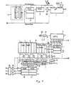
Der Bildschirmtextdecoder besteht aus einem Mikroprozessor 1, der die empfangenen Textsignale, Bedienfunktionssignale und Eingabe- undSteuergröBen auswertet und für die Verknüpfungssteuerung entsprechend programmiert ist. Als Programmspeicher für den Mikroprozessor dient ein Lesespeicher 2 (ROM). Als Datenspeicher wird ein auf maximal 64 kB erweiterungsfähiger Schreib/Lesespeicher 3 verwendet, in dem die empfangenen Textseiten abgelegt werden. Da der Mikroprozessor 1 aus Kapazitätsgründen über ein und dieselben Ausgänge sowohl die Adressen als auch die zeichenbezogenen Daten ausgibt, ist ein Adressenzwischenspeicher 23 vorgesehen, in welchem die Adressen auslesbar zwischengespeichert sind. Vor der Schnittstelle A - B ist ferner ein Chip-Selektor 4 vorgesehen, der zur Adressenaufschlüsselung die zu belegenden Speicher aktiviert. Der Mikroprozessor 1 wird über seinen Eingang 1.1 mit einer Clock-Frequenz, z.B. 12 MHz, getaktet. Die für den Prozessor notwendigen Unterfrequenzen werden durch eigene Teilung erzeugt. Die Eingänge 1.2 sowie die Ausgänge 1.3 und 1.4 sind mit einem Modem verbunden, das an die Telefonleitung angeschlossen ist und über die codierten Signale empfangen bzw. im Dialogverkehr an die Rechenzentrale ausgegeben wird. Der Eingang 1.5 ist mit einer Tastatur verbindbar, die der Einfachheit halber nicht dargestellt ist.Hierüber können die Programme eingeschrieben oder die entsprechenden Informationen zur Darstellung auf dem Bildschirm individuell eingegeben werden. Der Eingang 1.6 ist als Infrarot-Fernbedienungseingang vorgesehen. Hierüber werden die Steuerfunktionen von der Fernbedienung eingegeben, z.B. der Wiedergabebefehl von in den Vertikalaustastlücken des Fernsehsignals übertragenen Videotextsignalen, Umschalten auf Bildschirmtextempfang, Fernsehempfang usw.The screen text decoder consists of a
Die Schnittstelle A-B ist mit der Schnittstelle A'-B' verbunden. Die vom Mikroprozessor 1 zunächst in dem RAM 3 gespeicherten Seiten werden nach Empfang zwecks Darstellung wieder ausgelesen und der Zeicheninhalt mit dem im Programmspeicher 2 enthaltenen Zeichenvorrat verglichen. Der Mikroprozessor 1 stellt dabei fest, welche Struktur das Zeichen aufweist und welches Attribut ihm zuzuordnen ist. Die entsprechenden Daten werden attributsmäßig zeichenblockweise und punktorientiert .zeilenweise in den entsprechenden später beschriebenen Speichern 6 und 8 abgelegt.The interface A-B is connected to the interface A'-B '. The pages first stored in the
Die Abspeicherung der den Zeichen zugeordneten Daten sowie die Adressierung und Umadressierung erfolgen vom uP 1 gesteuert in der Weise, daß die Adressen über einen Adress- multiplexer 5 an die Adresseingänge eines statischen RAM-Speichers, der als Adressenspeicher 9 vorgesehen ist, angelegt werden. Es handelt sich dabei um einen mehrstufigen, der Zeichblockzahl angepaßten statischen RAM-Speicher (z.B. 1024 Plätze). Der Adressmultiplexer 5 wird nur während der Vertikalaustastzeit so umgeschaltet, daß die Adressen die zu belegenden Speicherplätze adressieren. Während der Schreibzeit des Bildes ist die Adressleitung über den Multiplexer 5 von dem µP 1 abgetrennt, hingegen die Steuerausgänge des CRT-Controllers 7 eingeschaltet. Zum Einspeichern der den Zeichen zugeordneten Informationen werden die vom Mikroprozessorausgang abgegebenen Daten über einen Datenbus und über Busschalter 10 zunächst in den Adressierspeicher 9 eingeschrieben. Die anstehenden Daten in dem Adressierspeicher 9 bilden die Adressen für den Attributspeicher 6. Die Daten werden in einem Zwischenspeicher 22 zwischengespeichert und getaktet gesteuert an den Attributspeicher 6 weitergegeben. Nunmehr werden Attributdaten über den Datenbus in dem Attributspeicher 6 abgelegt. Die Attribute sind zeichenbezogen, z.B. Hintergrundfarbe, Blinkzeichen und dergl. Sie werden über zugeordnete Busschalter vom µP 1 gesteuert eingelesen. Parallel hierzu erfolgt auch die Adressierung des punktorganisierten dynamischen Schreib /Lesespeichers, der ein 16 k dynamischer RAM-Speicher ist. Zwischengeschaltet ist eine Adressierlogik, die der Einfachheit halber nicht dargestellt ist. Diese ist dann notwendig, wenn der dynamischen Punktspeicher 8 nur seriell adressierbar ist. Die eingehenden Paralleladressen werden erst in. seriell einschreibbare Adressen umgesetzt, da der Speicher nur diese verarbeiten kann. Die einem jeden Attribut, das im statischen RAM 6 abgespeichert ist, zugeordneten punktorientierten Zeicheninformationen werden vom µP 1 ausgegeben und über die den einzelnen Speicher zugeordneten Busschalter 10 eingeschrieben. Damit erhält man im Punktspeicher 8 eins auf jeden Punkt eines darzustellenden Zeichens zugeordnete digitale Dateninformation. Es ist ersichtlich, daß nur durch Auslesen dieses dynamischen RAM-Speichers 8 bereits eine Darstellung einer gesamten Textseite erfolgen kann, da die Zeichenpunktinformationen lediglich zeilenweise dargestellt zu werden brauchen. Der Punktspeicher 8 dient insofern als Bildwiederholspeicher. Wird nun infolge einer rollenden Einschreibung neuer Datenzeilen in einen bestehenden Text, z.B. bei der Angabe von Fahrplänen, eine Datenzeile ausgetastet und eine neue eingegeben, so bewirkt der Adressierspeicher 9 die entsprechende Umadressierung. Es brauchen die neuen Seiten nicht mehr komplett eingegeben zu werden. Nach der Umadressierung im Adressierspeicher 9 werden automatisch durch die ausgehenden Informationen die Attribut- und Punktspeicher umorganisiert.The storing of the characters associated data as well as the addressing and readdressing done from uP 1 is controlled in such a manner that the address is provided via an address multiplexer 5 to the address inputs of a static RAM memory, the dress memory as A 9, are applied. It is a multi-level static RAM memory (eg 1024 spaces) adapted to the number of drawing blocks. The address multiplexer 5 is only during the vertical blanking time switched so that the addresses address the memory locations to be occupied. During the writing time of the image, the address line is separated from the
Die punktorientiert abgelegten Zeichendaten im dynamischen Punktspeicher 8 werden digitalcodiert über einem Punktschieberegister 11 und einer Multiplexschaltung 15 in einem Farbenspeicher 16 abgelegt. Die Adressierung erfolgt über den CRT-Controller 7, der die Umsetzung bewirkt, in der Weise, daß die über das Punktschieberegister 11 und den Mode-Multiplexer 15 anliegenden punktorientierten Daten unmittelbar zur Darstellung des Textes auf dem Bildschirm herangezogen werden können. Der CRT-Controller bewirkt aufgrund seiner Eigensteuerung dabei, daß im gleichen Abtastraster die Daten eingelesen und weitergegeben werden. Getaktet wird der CRT-Controller durch die Impulse eines Generators 20 mit einem nachgeschalteten Frequenzteiler 21, der die entsprechenden Clock-Frequenzen zur Steuerung der Systeme erzeugt.The point-oriented stored character data in the
Da in dem Attribut-Speicher 6 die Attribute für die Zeichen abgelegt sind, muß für die farbbildliche Darstellung dieser Information ebenfalls Sorge getragen werden. Hierzu werden die eingeschriebenen Daten über einen Zwischenspeicher und den Mode-Multiplexer 15 in einem Farbenspeicher 17 abgelegt. Die Einschreibung erfolgt dabei über den CRT-Controller 7 ebenfalls zeichenorientiert. Die beiden Ausgabe-Farbenspeicher 16 und 17 beinhalten sämtliche punkt- und zeichenadressierten Attribute, die für die Darstellung der Zeichen benötigt werden. Um Blinkfrequenzen ebenfalls einblenden zu können, ist ein Blinkspeicher 13 vorgesehen, in dem die verschiedenen Blinksequenzen festgehalten sind. Diese Blinksequenzen werden attributgesteuert über den Selektor 14 ausgelesen und als Information in dem Farbenspeicher 17 ebenfalls abgelegt. Die Verknüpfung erfolgt dabei über logische Gatter, -sofern dieses systembedingt notwendig ist.Since the attributes for the characters are stored in the
Wie bereits erwähnt, werden die Punktinformationen zeilenweise und die Attribute zeichenblockweise als Endausgabedaten in Farbenspeichern abgelegt. Zur Darstellung ist es notwendig, daß eine mit der Abtastfrequenz des Bildschirmtextes arbeitende Multiplexschaltung die abgelegten Zeilendaten in eine Matrixschaltung überträgt, die aus den Digitaldaten die für die Darstellung notwendigen analogen Größen für die Grundfarben Rot, Grün, Blau erzeugt. Die Ausgänge der Matrix 19 steuern z.B. direkt die Kathoden einer Farbbildröhre. Zur Wiederholung der einzelnen Bilder ist es lediglich erforderlich, daß über den CRT-Controller gesteuert die punktorientierten Daten nach dem Schreiben eines Einzelbildes immer wieder in die Farbenspeicher 16 unter Beachtung der Attribute eingelesen werden. Es ist ersichtlich, daß durch einfache Maßnahmen somit bei der Darstellung eines jeden Bildes nach Ablauf eines Bildschreibzyklus neue geänderte Textinformationen umorganisiert in dem dynamischen Punktspeicher 8 abgelegt werden können. Ein rollendes Einschreiben einzelner Zeilen ist somit auf einfache Weise möglich, ohne daß der Rechenaufwand wesentlich vergrößert werden muß, wodurch die Rechenzeiten in gewünschter Weise sehr klein gehalten werden können.As already mentioned, the point information is stored line by line and the attributes block by character as final output data in color memories. For the display, it is necessary that a multiplex circuit working with the sampling frequency of the screen text transmits the stored line data into a matrix circuit, which generates from the digital data the analog quantities necessary for the display for the basic colors red, green, blue. The outputs of the
Bei den verwendeten Speichern handelt es sich um:
- 1. Einen Programmspeicher
mit der Kapazität 8 kByte, max. 64 kB - 2. Einen Datenspeicher mit der Kapazität 2 -
r 16 kByte, max. kaskadiert 64 kB - 3. Einen Attributspeicher mit der Kapazität 2 kByte
- 4. Einen Adressierspeicher
mit der Kapazität 1 kByte - 5. Einen Punktspeicher mit der Kapazität 48 kByte
- 6. Einen Farbenspeicher mit der Kapazität 24 Byte
- 7. Einen weiteren Farbenspeicher mit der Kapazität 24 Byte
- 1. A program memory with a capacity of 8 kbytes, max. 64 kB
- 2. A data memory with the capacity 2 -
r 16 kByte, max. cascades 64 kB - 3. An attribute memory with a capacity of 2 kbytes
- 4. An addressing memory with a capacity of 1 kbyte
- 5. A point memory with a capacity of 48 kbytes
- 6. A color memory with a capacity of 24 bytes
- 7. Another color memory with a capacity of 24 bytes
Zum besseren Verständnis der Erfindung sei noch auf die Organisationen des Adressierspeichers, des Attributspeichers und des Punktspeichers sowie auf die Verknüpfungsebene zwischen den Schieberegistern mit den zugeordneten Attribut-, Punkt- und Farbenspeichern eingegangen.For a better understanding of the invention, the organizations of the addressing memory, the attribute memory and the point memory as well as the link level between the shift registers with the assigned attribute, point and color memories are discussed.
Die Organisation des Adressierspeichers ist folgende:
- Zur schnellen Umschichtung großer Datenmengen auf dem Bildschirm wird der Adressierspeicher 9 verwendet. Die Adressen einzelner Zeichen werden dort schnell und einfach manipuliert, ohne daß größere zeitraubende Umschichtungen im punktorientierten Wiederholspeicher nötig werden. Normalerweise wird die Adresse nicht verändert, d.h. unter der Adresse 0 ist die Adresse 0 für den Bildwiederholspeicher abgelegt usw.:

- The addressing memory 9 is used for quickly rearranging large amounts of data on the screen. The addresses of individual characters are manipulated quickly and easily there without the need for major time-consuming rearrangements in the point-oriented repetitive memory. The address is normally not changed, i.e. address 0 for the image repetition memory is stored under address 0, etc.:
Wird im Zuge einer Scrolling-Prozedur der oben gekennzeichnete Bereich als Scrolling-Bereich festgelegt und wird dieser Bereich von unten her mit einer neuen Zeile aufgefüllt, so ergibt sich folgende Verteilung:

Der Bereich 40 ... 79 des Bildwiederholspeichers wurde dabei durch eine neue Zeile ersetzt. Die Adressen des Scrolling-Bereiches wurden gleichzeitig verändert.The area 40 ... 79 of the refresh memory was replaced by a new line. The addresses of the scrolling area were changed at the same time.
Die Organisation des Attributspeichers ist folgende:
- Der Attributspeicher ist zeichenorientiert organisiert und mit vier statischen 4 kbit RAMS, die
ihrerseits 1 k x 4 organisiert sind, aufgebaut.
- Die Speicherorganisation des Punktspeichers ist folgende:
- Der Bildwiederholspeicher ist punktorientiert organisiert und besteht aus sechs dynamischen 64 kbit RAMS, die
ihrerseits 16 k x 4 organisiert sind. Dadurch erhält man eine für die Darstellung günstige Breite von 24 Bit, die entsprechend dem Mode wie folgt belegt wird:
- The attribute memory is organized in a character-oriented manner and is constructed with four static 4 kbit RAMS, which in turn are organized 1 kx 4.
- The memory organization of the point memory is as follows:
- The refresh memory is organized point-oriented and consists of six dynamic 64 kbit RAMS, which in turn are organized 16 kx 4. This results in a width of 24 bits that is favorable for the display, which is assigned according to the mode as follows:
Die Verknüpfungsebene zwischen dem punktorientierten Speicher und dem Attributspeicher sowie den Farbenspeichern ist folgende:
- Die Verknüpfungsebene liegt zwischen den Schieberegistern mit den zugeordneten Attributzwischenspeichern und den Farbenspeichern. Die beiden Multiplexer 15 selektieren verschiedene 4 bit Eingangsinformationen:Punktinformation am Ausgang des Schieberegisters DOT Ferngeladene oder Basisfarben (auch CS für Farbenspeicher) beide Informationen können verdrängt werden und die Darstellung der Hintergrundfarbe erzwungen werden durch


- The link level lies between the shift registers with the assigned attribute buffers and the color buffers. The two multiplexers 15 select different 4-bit input information: Point information at the output of the shift register DOT Remote or basic colors (also CS for color memory) both information can be suppressed and the display of the background color can be enforced by
Der Blinkselektor 14 selektiert über drei Attributeingänge A, B, C acht verschiedene Blinksequenzen, die an dem Blinkspeicher 13 anliegen.The
Die Wirkungsweise und die Ansteuermöglichkeiten sowie die Ausgabe der Daten über den CRT-Controller sollen hier nicht näher beschrieben werden. Es sei auf einen bekannten CRT-Controller der Firma Motorola, MC 6845, verwiesen, der im Datenbuch Motorola "Semiconductors, Microcomputer Component", Ausgabe 1979, Seite 193 und ff., beschrieben ist. Dabei ist darauf zu achten, daß die vom CRT-Controller vollzogenen Steuerfunktionen ablaufgemäß vom Microcomputer bestimmt werden. Der Mikrocomputer und der CRT-Controller müssen deshalb mit der geeigneten Software programmiert werden.The mode of operation and the control options as well as the output of the data via the CRT controller are not to be described in more detail here. Reference is made to a known CRT controller from Motorola, MC 6845, which is described in the Motorola data book "Semiconductors, Microcomputer Component", 1979 edition, page 193 and ff. It is important to ensure that the control functions performed by the CRT controller are determined by the microcomputer in accordance with the process. The microcomputer and the CRT controller must therefore be programmed with the appropriate software.
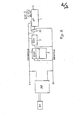
Der Bildschirmtextdecoder nach Fig. 2 besteht entsprechend der Ausführung nach Fig. 1 aus einem Mikroprozessor 1, der die empfangenen Textsignale, Bedienfunktionssignale und Eingabe- und Steuergrößen auswertet und für die Verknüpfungssteuerung entsprechend programmiert ist. Als Programmspeicher für den Mikroprozessor dient ein Lesespeicher 2 (ROM). Als Datenspeicher wird ein auf max. 64 kB erweiterungs- fähiger Schreib/Lesespeicher 3 verwendet, in welchem die empfangenen Signale seitenweise abgelegt werden. Da der Mikroprozessor 1 aus Kapazitätsgründen über ein und denselben Ausgang sowohl die Adressen als auch die zeichenbezogenen Daten ausgibt, ist ein Adressenzwischenspeicher 23 vorgesehen, in welchem die auf jeden Punkt eines Zeichens bezogenen Adressen zwischengespeichert sind. Am Ausgang befinden sich die Schnittstellen A und B, an die entweder eine signalverarbeitende Schaltung für die Darstellung des empfangenen Bildschirmtextes auf einem Bildschirm anschließbar ist oder, wie im Ausführungsbeispiel dargestellt, eine Druckersteuerung 30. Eine bekannte Druckersteuerung ist beispielsweise in der DE-OS 31 31 953 für einen Thermodrucker beschrieben. In der Regel werden die empfangenen Zeichen in einem Zeichenpuffer zwischengespeichert und dann einem Zeichendecoder zugeführt, der die empfangenen Zeichen für die Darstellung mit dem2 consists of a
Drucker in den notwendigen Code umsetzt. Die so erhaltenen Signale werden von einer Treiberschaltung zur Ansteuerung des Druckerkopfes zugeführt. Auf derartige hier als bekannt vorausgesetzte Druckersteuerungen wird im weiteren nicht mehr näher eingegangen. Es sind verschiedene punktgesteuerte Drucker bekannt, wie Thermodrucker, Nadeldrucker, Tintendrucker usw. Alle arbeiten entweder nach dem Matrixsystem oder durch Einzelpunktsteuerungsverfahren. Die Druckersteuerung steuert den Druckkopf 31, der die darzustellenden Symbole, Zeichen und Grafiken auf dem Aufzeichnungsträger ausdruckt. Der Teilnehmer kann darüber hinaus über die an dem Mikroprozessor 1 angeschlossene Eingabetastatur in den Dialogverkehr mit der Bildschirmtextzentrale oder einen hierüber angeschlossenen Rechner treten. Er erhält sofort einen ausgedruckten Text der Bildschirmtextzentrale. Für die Auswahl der entsprechenden auszudruckenden Seiten ist es angebracht, an den Schnittstellen A-B eine Schaltungsanordnung zur Darstellung des Textes auf einem Bildschirm anzuordnen. Der Drucker sollte dann jedoch mit einem Zeichenpuffer versehen sein, in dem die einzelnen Informationen für die Anpassung an die Druckergeschwindigkeit zwischengespeichert werden. Der Zeichenpuffer wird mit einer eigenen Clock-Frequenz ausgelesen.Converts the printer into the necessary code. The signals thus obtained are supplied by a driver circuit for controlling the printer head. Such printer controls, which are assumed to be known here, will not be discussed in more detail below. Various point-controlled printers are known, such as thermal printers, dot matrix printers, ink printers, etc. All operate either according to the matrix system or by single-point control methods. The printer controller controls the
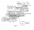
In Fig. 3 ist ein Bildschirmtextdecoder nach Fig. 1 dargestellt, der vorrangig dazu dient, den Bildschirmtext auf dem Bildschirm darzustellen. Zusätzlich ist die Interface-Schaltung für einen Drucker 31 vorgesehen.FIG. 3 shows a screen text decoder according to FIG. 1, which primarily serves to display the screen text on the screen. In addition, the interface circuit is provided for a
Bei der Verwendung eines derartigen Bildschirmtextdecoders ist die Druckersteuerung 30, die zur Anpassung der Schreibgeschwindigkeit einen eigenen Datenspeicher als Zeichenpuffer aufweisen sollte, über ein Punktschieberegister 11 an den Punktspeicher angeschlossen. Das Punktschieberegister 11 wird von der Computersteuereinrichtung 1. oder dem CRT-Controller 7 gesteuert. Die so übertragenen punktbezogenen Daten werden von dem Drucker 31 über die Steuerung 30 gesteuert ausgedruckt.When using such a screen text decoder, the
Das erfindungsgemäße Verfahren ist nicht nur auf die dargestellten Ausführungsbeispiele beschränkt. An die Stelle der punktorientierten Ablage der empfangenen Zeichen in einem dynamischen RAM 8 und den zugeordneten Schaltungen für die Punktdarstellung kann auch ein Zeichengenerator treten, der eine direkte Darstellung der empfangenen und mittels der ersten Stufe umgesetzten punktbezogenen Zeichen ermöglicht und diese zwischenspeichert. In diesem Fall empfiehlt es sich, nach Fig. 1 den Drucker unmittelbar an die Schnittstelle A-B anzuschließen.The method according to the invention is not only limited to the exemplary embodiments shown. Instead of the point-oriented storage of the received characters in a
Claims (15)
daß ein Schreib/Lese/Adressierspeicher (9) vorgesehen ist, in den von der Computersteuereinrichtung (1) gesteuert, nur während der Vertikalaustastzeit bei der Textdarstellung auf dem Bildschirm die einzelnen Zeicheninformationen zeichenblockweise adressiert eingeschrieben werden, daß die im Adressierspeicher (9) gespeicherten Daten, die in einem auslesbaren Zwischenspeicher (22) gespeichert sind, die Adresse für eine Zeichenattributinformation, die in einen Schreib/Lese/Attributspeicher (6) eingeschrieben wird, und die Unteradresse für jede Zeile, die in einem dynamischen Punktspeicher, in dem die Zeichen punktorganisiert abgelegt sind, gespeichert ist, bilden,
daß die aus dem Seitenspeicher (3) ausgelesenen, einem jeden Zeichen im Zeichenspeicher (2) zugeordneten Attribute über die Computersteuereinrichtung (1) in dem jeweiligen adressierten Speicherplatz des Attributspeichers (6) digitalcodiert abgelegt werden,
daß in dem dynamischen Schreib/Lese-Punktspeicher (8), der parallel zum Attributspeicher (6) adressiert ist, von der Computersteuereinrichtung (1) gesteuert die Informationen eines jeden Punktes eines Zeichens punktorientiert abgelegt werden,
daß die auf einen Zeichenpunkt bezogenen, im Punktspeicher (8) abgelegten, von einer Steuereinrichtung (7) für die mit den Synchronimpulsen des Bildschirmgerätes synchronisierte Darstellung des Bildschirmtextes adressgesteuert und die zeichenorientierten Attributinformationen aus dem Attribut- speicher (6) von derselben Steuereinrichtung (7) gesteuert und miteinander derart verknüpft und decodiert ausgegeben werden, daß die ausgegebenen Größen direkt von den Videosignalverarbeitungsschaltungen des Bildschirmgerätes verarbeitet und auf dem Bildschirm dargestellt werden.1. Method and circuit arrangement for the visual representation of text, graphics and symbols on screens of monitors or television receiving devices and / or by means of point-controlled printers, such as thermal, dot matrix and ink printers, and for output to peripheral devices with a readable page memory in which the received text information are stored page by page, and a readable character memory, in which each address is assigned to a location on the screen, and a readable attribute memory linked to the character memory and a computer control device via which the character and attribute memory can be written, and a video signal generation circuit, in which the information read from the character and attribute memory is converted into video signals which can be reproduced on the screen, characterized in that
that a write / read / address memory (9) is provided, in which the computer character device (1) controls, only during the vertical blanking time in the text display on the screen, the individual character information is written in blocks of characters, that the data stored in the address memory (9) stored in a readable buffer (22), the address for character attribute information written in a read / write / attribute memory (6), and the subaddress for each line stored in a dynamic point memory in which the characters are point organized are stored, saved, form,
that the attributes read from the page memory (3) and assigned to each character in the character memory (2) are stored digitally coded in the respective addressed memory location of the attribute memory (6) via the computer control device (1),
that in the dynamic read / write point memory (8), which is addressed parallel to the attribute memory (6), the information of each point of a character is stored in a point-oriented manner by the computer control device (1),
that the character-related, stored in the point memory (8) is address-controlled by a control device (7) for the display of the screen text synchronized with the sync pulses of the display device, and the character-oriented attribute information from the attribute memory (6) by the same control device (7) are controlled and linked to one another and outputted in such a way that the output variables are processed directly by the video signal processing circuits of the display device and displayed on the display screen.
daß die dem Mikroprozessor zugeordneten Datenspeicher (RAM) als Seitenspeicher (3) für die seitenweise Ablage der Textinformation vorgesehen sind,
daß als Programmspeicher des Mikroprozessors ein die Zeicheninformationen fest beinhaltender Zeichen-Programmspeicher (ROM) (2) vorgesehen ist,
daß ferner zur Aktivierung der nachfolgenden Speicher (6, 8, 9) ein Chip-Selektor (4) vorgesehen ist, der vom Mikrocomputer gesteuert wird,
daß der Mikroprozessor (1) die den einzelnen Zeichen zugeordneten Adressen und Daten an Adress- und Busleitungen abgibt,
daß. nur während der Vertikalaustastzeit die Adressen und die den Zeichen zugeordneten Daten über einen Multiplexer (5) in den aktivierten Speicher einschreibbar sind, daß die punkt- und zeichenblockorientierten Informationen über den CRT-Controller (7) adressiert zur Darstellung an die Zwischenspeicher (Farbenspeicher) über entsprechende Punktschieberegister durchschaltbar sind.13. Circuit arrangement for carrying out the method according to one of claims 1,9 to 12, characterized in that a microprocessor is provided as the central computer control unit, the inputs (1.2, 1.3, 1.4, etc.), some of which have a modem for connection are connected to a telephone network and others are provided for receiving digitized text signals,
that the data memories (RAM) assigned to the microprocessor are provided as page memories (3) for the page-by-page storage of the text information,
that a character program memory (ROM) (2) which permanently contains the character information is provided as the program memory of the microprocessor,
that a chip selector (4), which is controlled by the microcomputer, is also provided for activating the subsequent memories (6, 8, 9),
that the microprocessor (1) delivers the addresses and data assigned to the individual characters to address and bus lines,
that. The addresses and the data assigned to the characters can only be written into the activated memory via a multiplexer (5) during the vertical blanking time, so that the point and character block-oriented information is addressed via the CRT controller (7) for display to the buffer (color memory) corresponding point shift registers can be switched through.
Priority Applications (1)
| Application Number | Priority Date | Filing Date | Title |
|---|---|---|---|
| AT83105772T ATE45654T1 (en) | 1982-06-24 | 1983-06-13 | CIRCUIT ARRANGEMENT FOR THE PICTURED REPRESENTATION OF TEXT, GRAPHICS AND SYMBOLS ON SCREENS OF MONITORS AND/OR BY MEANS OF POINT-CONTROLLED PRINTER. |
Applications Claiming Priority (4)
| Application Number | Priority Date | Filing Date | Title |
|---|---|---|---|
| DE3223489 | 1982-06-24 | ||
| DE19823223489 DE3223489C2 (en) | 1982-06-24 | 1982-06-24 | Circuit arrangement for the colored display of texts, graphics and symbols on the screen of a monitor or color television receiver |
| DE19823240141 DE3240141A1 (en) | 1982-10-29 | 1982-10-29 | Method and circuit arrangement for the pictorial representation of texts, graphics and symbols on screens of monitors and/or by means of dot-controlled printers |
| DE3240141 | 1982-10-29 |
Publications (3)
| Publication Number | Publication Date |
|---|---|
| EP0099469A2 true EP0099469A2 (en) | 1984-02-01 |
| EP0099469A3 EP0099469A3 (en) | 1986-04-09 |
| EP0099469B1 EP0099469B1 (en) | 1989-08-16 |
Family
ID=25802583
Family Applications (1)
| Application Number | Title | Priority Date | Filing Date |
|---|---|---|---|
| EP83105772A Expired EP0099469B1 (en) | 1982-06-24 | 1983-06-13 | System for the representation of text, graphics and symbols on monitor screens and/or with matrix printers |
Country Status (2)
| Country | Link |
|---|---|
| EP (1) | EP0099469B1 (en) |
| DE (1) | DE3380436D1 (en) |
Cited By (3)
| Publication number | Priority date | Publication date | Assignee | Title |
|---|---|---|---|---|
| EP0125878A2 (en) * | 1983-05-13 | 1984-11-21 | Ing. C. Olivetti & C., S.p.A. | Print apparatus for videotext terminal |
| EP0189140A2 (en) * | 1985-01-24 | 1986-07-30 | Siemens Aktiengesellschaft | Control system for raster scan displays |
| WO1999053435A2 (en) * | 1998-04-10 | 1999-10-21 | Minnesota Mining And Manufacturing Company | Terminal for libraries and the like |
Citations (2)
| Publication number | Priority date | Publication date | Assignee | Title |
|---|---|---|---|---|
| EP0012858A1 (en) * | 1978-12-26 | 1980-07-09 | International Business Machines Corporation | Display and recording apparatus |
| FR2492618A1 (en) * | 1980-10-16 | 1982-04-23 | Sony Corp | COLOR INFORMATION DISPLAY APPARATUS |
-
1983
- 1983-06-13 DE DE8383105772T patent/DE3380436D1/en not_active Expired
- 1983-06-13 EP EP83105772A patent/EP0099469B1/en not_active Expired
Patent Citations (2)
| Publication number | Priority date | Publication date | Assignee | Title |
|---|---|---|---|---|
| EP0012858A1 (en) * | 1978-12-26 | 1980-07-09 | International Business Machines Corporation | Display and recording apparatus |
| FR2492618A1 (en) * | 1980-10-16 | 1982-04-23 | Sony Corp | COLOR INFORMATION DISPLAY APPARATUS |
Non-Patent Citations (1)
| Title |
|---|
| ELECTRONIQUE INDUSTRIELLE, Nr. 21, 1. Oktober 1981, Seiten 33-36, Paris, FR; PH. LAMBINET: "Réalisation d'un terminal graphique autour du processeur intégré EF9365" * |
Cited By (13)
| Publication number | Priority date | Publication date | Assignee | Title |
|---|---|---|---|---|
| EP0125878A2 (en) * | 1983-05-13 | 1984-11-21 | Ing. C. Olivetti & C., S.p.A. | Print apparatus for videotext terminal |
| EP0125878A3 (en) * | 1983-05-13 | 1987-04-15 | Ing. C. Olivetti & C., S.P.A. | Print apparatus for videotext terminal |
| EP0189140A2 (en) * | 1985-01-24 | 1986-07-30 | Siemens Aktiengesellschaft | Control system for raster scan displays |
| EP0189140A3 (en) * | 1985-01-24 | 1990-05-30 | Siemens Aktiengesellschaft | Control system for raster scan displays |
| US6369709B1 (en) | 1998-04-10 | 2002-04-09 | 3M Innovative Properties Company | Terminal for libraries and the like |
| WO1999053435A3 (en) * | 1998-04-10 | 2000-04-27 | Minnesota Mining & Mfg | Terminal for libraries and the like |
| WO1999053435A2 (en) * | 1998-04-10 | 1999-10-21 | Minnesota Mining And Manufacturing Company | Terminal for libraries and the like |
| US6464138B1 (en) | 1998-04-10 | 2002-10-15 | Minnesota Mining And Manufacturing Company | Terminal for libraries and the like |
| US6542070B1 (en) | 1998-04-10 | 2003-04-01 | Minnesota Mining And Manufacturing Company | Terminal for libraries and the like |
| US6549141B1 (en) | 1998-04-10 | 2003-04-15 | Minnesota Mining And Manufacturing Company | Terminal for libraries and the like |
| US6750777B2 (en) | 1998-04-10 | 2004-06-15 | 3M Innovative Properties Company | Terminal for libraries and the like |
| US6857568B1 (en) | 1998-04-10 | 2005-02-22 | 3M Innovative Properties Company | Terminal for libraries and the like |
| US8002182B2 (en) | 1998-04-10 | 2011-08-23 | 3M Innovative Properties Company | System for processing financial transactions in a self-service library terminal |
Also Published As
| Publication number | Publication date |
|---|---|
| EP0099469A3 (en) | 1986-04-09 |
| DE3380436D1 (en) | 1989-09-21 |
| EP0099469B1 (en) | 1989-08-16 |
Similar Documents
| Publication | Publication Date | Title |
|---|---|---|
| DE2438272C3 (en) | Display control device for positioning a luminous mark on a display device | |
| DE3443630C2 (en) | Decoder for teletext-like signals | |
| DE2703579C2 (en) | Arrangement for processing video signals | |
| DE4332573C2 (en) | Videographic system for displaying waveforms on a video monitor | |
| DE3736195C2 (en) | Raster video display device | |
| DE2651543A1 (en) | DIGITAL GRID DISPLAY SYSTEM | |
| DE3508336C2 (en) | ||
| DE2223332A1 (en) | Device for the visible display of data on a playback device | |
| DE3218815A1 (en) | METHOD FOR USING A STORAGE DEVICE FOR A DISPLAY SYSTEM | |
| DE1774682B2 (en) | Device for visible data reproduction | |
| DE3248978C2 (en) | ||
| DE2438203C3 (en) | DISPLAY DEVICE | |
| EP0038002B1 (en) | System for displaying characters on a screen | |
| DE3723590C2 (en) | Circuit arrangement for displaying information on a screen by overlaying several individual images | |
| DE3223489C2 (en) | Circuit arrangement for the colored display of texts, graphics and symbols on the screen of a monitor or color television receiver | |
| DE2920230A1 (en) | VECTOR GENERATOR FOR RECORDER DATA STATION | |
| DE69829163T2 (en) | Method and apparatus for using interpolation line buffers as pixel tables | |
| DE3516416C2 (en) | ||
| EP0006131A1 (en) | Method for transmitting recordings containing miscellaneous representations to a display screen, particularly in telephone systems | |
| DE2651672A1 (en) | DATA DECODING ARRANGEMENT FOR A DISPLAY DEVICE | |
| DE2855731C2 (en) | Process and device for the colored representation of information | |
| DE2741161B2 (en) | Circuit arrangement for a display system for displaying a pattern | |
| EP0099469B1 (en) | System for the representation of text, graphics and symbols on monitor screens and/or with matrix printers | |
| DE3520472A1 (en) | VIDEO SCREEN CONTROL DEVICE | |
| DE3240141A1 (en) | Method and circuit arrangement for the pictorial representation of texts, graphics and symbols on screens of monitors and/or by means of dot-controlled printers |
Legal Events
| Date | Code | Title | Description |
|---|---|---|---|
| PUAI | Public reference made under article 153(3) epc to a published international application that has entered the european phase |
Free format text: ORIGINAL CODE: 0009012 |
|
| AK | Designated contracting states |
Designated state(s): AT BE CH DE FR GB IT LI NL SE |
|
| 17P | Request for examination filed |
Effective date: 19850521 |
|
| PUAL | Search report despatched |
Free format text: ORIGINAL CODE: 0009013 |
|
| AK | Designated contracting states |
Kind code of ref document: A3 Designated state(s): AT BE CH DE FR GB IT LI NL SE |
|
| 17Q | First examination report despatched |
Effective date: 19880211 |
|
| ITF | It: translation for a ep patent filed |
Owner name: DE DOMINICIS & MAYER S.R.L. |
|
| GRAA | (expected) grant |
Free format text: ORIGINAL CODE: 0009210 |
|
| AK | Designated contracting states |
Kind code of ref document: B1 Designated state(s): AT BE CH DE FR GB IT LI NL SE |
|
| REF | Corresponds to: |
Ref document number: 45654 Country of ref document: AT Date of ref document: 19890915 Kind code of ref document: T |
|
| REF | Corresponds to: |
Ref document number: 3380436 Country of ref document: DE Date of ref document: 19890921 |
|
| ET | Fr: translation filed | ||
| GBT | Gb: translation of ep patent filed (gb section 77(6)(a)/1977) | ||
| PLBE | No opposition filed within time limit |
Free format text: ORIGINAL CODE: 0009261 |
|
| STAA | Information on the status of an ep patent application or granted ep patent |
Free format text: STATUS: NO OPPOSITION FILED WITHIN TIME LIMIT |
|
| 26N | No opposition filed | ||
| ITTA | It: last paid annual fee | ||
| PGFP | Annual fee paid to national office [announced via postgrant information from national office to epo] |
Ref country code: SE Payment date: 19930507 Year of fee payment: 11 |
|
| PGFP | Annual fee paid to national office [announced via postgrant information from national office to epo] |
Ref country code: GB Payment date: 19930604 Year of fee payment: 11 |
|
| PGFP | Annual fee paid to national office [announced via postgrant information from national office to epo] |
Ref country code: BE Payment date: 19930609 Year of fee payment: 11 |
|
| PGFP | Annual fee paid to national office [announced via postgrant information from national office to epo] |
Ref country code: FR Payment date: 19930611 Year of fee payment: 11 |
|
| PGFP | Annual fee paid to national office [announced via postgrant information from national office to epo] |
Ref country code: CH Payment date: 19930623 Year of fee payment: 11 |
|
| PGFP | Annual fee paid to national office [announced via postgrant information from national office to epo] |
Ref country code: NL Payment date: 19930630 Year of fee payment: 11 Ref country code: AT Payment date: 19930630 Year of fee payment: 11 |
|
| PGFP | Annual fee paid to national office [announced via postgrant information from national office to epo] |
Ref country code: DE Payment date: 19930803 Year of fee payment: 11 |
|
| PG25 | Lapsed in a contracting state [announced via postgrant information from national office to epo] |
Ref country code: GB Effective date: 19940613 Ref country code: AT Effective date: 19940613 |
|
| PG25 | Lapsed in a contracting state [announced via postgrant information from national office to epo] |
Ref country code: SE Effective date: 19940614 |
|
| PG25 | Lapsed in a contracting state [announced via postgrant information from national office to epo] |
Ref country code: LI Effective date: 19940630 Ref country code: CH Effective date: 19940630 Ref country code: BE Effective date: 19940630 |
|
| BERE | Be: lapsed |
Owner name: LOEWE OPTA G.M.B.H. Effective date: 19940630 |
|
| PG25 | Lapsed in a contracting state [announced via postgrant information from national office to epo] |
Ref country code: NL Effective date: 19950101 |
|
| EUG | Se: european patent has lapsed |
Ref document number: 83105772.4 Effective date: 19950110 |
|
| GBPC | Gb: european patent ceased through non-payment of renewal fee |
Effective date: 19940613 |
|
| NLV4 | Nl: lapsed or anulled due to non-payment of the annual fee | ||
| PG25 | Lapsed in a contracting state [announced via postgrant information from national office to epo] |
Ref country code: FR Effective date: 19950228 |
|
| REG | Reference to a national code |
Ref country code: CH Ref legal event code: PL |
|
| PG25 | Lapsed in a contracting state [announced via postgrant information from national office to epo] |
Ref country code: DE Effective date: 19950301 |
|
| EUG | Se: european patent has lapsed |
Ref document number: 83105772.4 |
|
| REG | Reference to a national code |
Ref country code: FR Ref legal event code: ST |