EP0092763A2 - Magnetic write device - Google Patents
Magnetic write device Download PDFInfo
- Publication number
- EP0092763A2 EP0092763A2 EP83103727A EP83103727A EP0092763A2 EP 0092763 A2 EP0092763 A2 EP 0092763A2 EP 83103727 A EP83103727 A EP 83103727A EP 83103727 A EP83103727 A EP 83103727A EP 0092763 A2 EP0092763 A2 EP 0092763A2
- Authority
- EP
- European Patent Office
- Prior art keywords
- coercive force
- magnetic
- ticket
- information
- write device
- Prior art date
- Legal status (The legal status is an assumption and is not a legal conclusion. Google has not performed a legal analysis and makes no representation as to the accuracy of the status listed.)
- Granted
Links
Images


Classifications
-
- G—PHYSICS
- G07—CHECKING-DEVICES
- G07F—COIN-FREED OR LIKE APPARATUS
- G07F7/00—Mechanisms actuated by objects other than coins to free or to actuate vending, hiring, coin or paper currency dispensing or refunding apparatus
- G07F7/08—Mechanisms actuated by objects other than coins to free or to actuate vending, hiring, coin or paper currency dispensing or refunding apparatus by coded identity card or credit card or other personal identification means
- G07F7/086—Mechanisms actuated by objects other than coins to free or to actuate vending, hiring, coin or paper currency dispensing or refunding apparatus by coded identity card or credit card or other personal identification means by passive credit-cards adapted therefor, e.g. constructive particularities to avoid counterfeiting, e.g. by inclusion of a physical or chemical security-layer
-
- G—PHYSICS
- G06—COMPUTING; CALCULATING OR COUNTING
- G06K—GRAPHICAL DATA READING; PRESENTATION OF DATA; RECORD CARRIERS; HANDLING RECORD CARRIERS
- G06K1/00—Methods or arrangements for marking the record carrier in digital fashion
- G06K1/12—Methods or arrangements for marking the record carrier in digital fashion otherwise than by punching
- G06K1/125—Methods or arrangements for marking the record carrier in digital fashion otherwise than by punching by magnetic means
-
- G—PHYSICS
- G11—INFORMATION STORAGE
- G11B—INFORMATION STORAGE BASED ON RELATIVE MOVEMENT BETWEEN RECORD CARRIER AND TRANSDUCER
- G11B5/00—Recording by magnetisation or demagnetisation of a record carrier; Reproducing by magnetic means; Record carriers therefor
- G11B5/02—Recording, reproducing, or erasing methods; Read, write or erase circuits therefor
Definitions
- the present invention relates to a magnetic write device which is provided in a ticket vending machine or ticket checking apparatus used in traffic facilities such as a railway stations, airports, etc., or an automatic transaction apparatus used in banking facilities to write magnetic information.
- Magnetic cards have heretofore been widely used as data input media in automatized equipment such as an automatic ticket checking apparatus or automatic cash dispensing machine or in terminal devices for computers.
- the magnetic card is formed by coating a base medium, such as a polyester film, with y-Fe20 3 .
- Oxides such as y-Fe20 3 and metal powder, or thin metal film which is formed of a composition such as Fe-Co-Ni, have been employed as the magnetic material.
- Magnetic characteristics such as saturation flux density, coercive force and rectangular ratio become important factors of the magnetic material.
- the conventional magnetic card has employed a magnetic material which had 1.25 to 1.40 maxwells/centimeter of residual flux density, 300 to 600 Oersted of coercive force, and a rectangular ratio larger than 0.7.
- the reduction in the magnetization or the demagnetization of the magnetic recording information may be caused by an external magnetic field, such as those generated from speakers of televisions and stereophonic players, electric products such as refrigerators, magnets for toys, or magnets of locks for handbags.
- an external magnetic field such as those generated from speakers of televisions and stereophonic players, electric products such as refrigerators, magnets for toys, or magnets of locks for handbags.
- the magnetic recording information of the medium can be almost completely demagnetized.
- a magnet for a toy or a lock has a DC magnetic field of 500 Oe to 1,000 Oe.
- a DC magnetic field directly contacts a magnetic card which has approx; 600 Oe of coercive force, the magnetic recording information of the card is almost completely demagnetized.
- a magnetic recording medium which has a high coercive force such as 2,000 Oe to 3,000 Oe and which is affected very little by the influence of an external magnetic field is used.
- a magnetic recording medium which has such a high coercive force necessitates the application of a high magnetic field at the time of recording information.
- a magnetic card with a high coercive force becomes expensive.
- magnetic recording media each of which has a relatively low coercive force such as 300 Oe, are used.
- a ticket which is used for a long period of time such as a pass, a commutation, or season ticket has a possibility of being frequently affected by a strong external magnetic field during such long term use. Accordingly, it is desirable to employ magnetic recording media of high coercive force.
- media of low coercive force are widely used at present, and it would be quite difficult under the present circumstances to introduce magnetic read-write devices using media of high coercive force.
- a magnetic write device which comprises means for discriminating the magnitude of coercive force of magnetic recording media and means for controlling the intensity of a magnetic field for recording information in response to the discriminated result of this discriminating means.
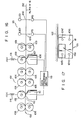
- Fig. 1 schematically shows a traffic system.
- a one-way ticket vending machine 11, a multiple trip ticket vending machine 12 and a pass vending machine 13 are installed in a station. These vending machines 11, 12 and 13 automatically sell a one-way ticket 14, a multiple trip ticket 15 and a pass 16, respectively.
- a magnetic layer coated with a magnetic material is formed on the back surface of each of the tickets 14 and 15, and the pass 16.
- Various pieces of information are recorded in the magnetic layers of the tickets 14 and 15, and the pass 16 in accordance with the encode formats of Japanese Cybernetics Committee standards.
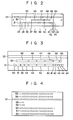
- first track 31, second track 32 and clock track 33 are formed in the region of the magnetic layer of a rectangle approx. 30 mm x 57 mm.
- 'Line information which includes ticket direction discrimination data 34, month data 35, tens place date data 36, ones place date data 37, division data 38, station sequence data 39, section (fare) data 40, a communication bit 41, a ticket type bit 42, a spare bit 43 and a parity bit 44 provided at both ends is stored in the first track 31.
- Another company's line information which includes a blank bit 45, division data 46, station sequence data 47, section (fare) data '48, a blank bit 49 and a parity bit 50 is stored in the second track 32.
- first and second tracks 31, 32 and clock track 33 are provided, as in the one-way ticket.
- the same information is stored in the second track 32 and the clock track 33 as in the one-way ticket in Fig. 2.
- the first track of the multiple trip ticket stores an effective end month data 51, tens place effective end date data 52, ones place effective end date data 53, a multiple trip ticket code (coded data for identifying a specific division code as the multiple trip ticket code or part thereof) 54, and multiple trip ticket type data (coded data for indentifying the issuing year of the multiple trip ticket in accordance with station sequence data which is altered every year) 55.
- fare (section) data is printed on the front surface of the multiple trip ticket ticket fare (section) data is printed.
- the encode format of the pass shown in Fig. 4 eight magnetic tracks from the first track 55 to the eighth track 62 are provided in the magnetic layer of 57 mm x 85 mm.
- the first, second, sixth, seventh and eighth tracks are data tracks which record the discrimination data
- the third track 57 is a clock track.
- the fourth and fifth tracks 58 and. 59 are tracks to be written by an automatic ticket checking apparatus. These tracks 58 and 59 store error occurrence numbers in case a reading error occurs when information is read from the pass by the automatic ticket checking apparatus. When the number of reading errors exceeds a predetermined number, the pass is considered an information breakdown ticket.
- Both high and low coercive force operations are generally provided in the ticket and pass vending machines 11, 12 and 13, which can issue either a high or low coercive force ticket or pass.
- both the ticket and pass have low and high coercive forces.
- a high and low coercive force vending machine is further employed.
- the low coercive force vending machine is widely used for vending tickets and passes.
- the high coercive force vending machine is modified, and is used for issuing a long-term use ticket, i.e., passes and multiple trip tickets.
- the high and low coercive force vending machine is constructed to issue, for example, one-way tickets with low coercive force magnetic media and to issue multiple trip tickets or passes with high coercive force magnetic media.
- the write section of the high and low coercive force vending machine is constructed, for example, as shown in Fig. 5.
- an exciting coil 72 which has a center tap 73 is wound on a write magnetic head 71.
- Lead wires 74 and 74 of both ends of the coil 72 are respectively grounded through the collector-emitter paths of transistors Trl and Tr2.
- a lead wire 76 of the tap 73 is connected through a resistor Rl to a power source voltage Vcc, and is connected in series through the collector-emitter path of a transistor Tr3 and a resistor R2 to the power voltage Vcc.
- a low level signal is inputted to the transistor Tr3, which is, in turn, turned OFF.
- high and low level signals are selectively supplied to the bases of the transistors Trl and Tr2 according to a write signal.
- the transistors Trl and Tr2 are respectively turned “ON” and "OFF”.
- a current I 1 flows to the coil 72 through the resistor Rl, a lead line 76, the coil 72, a lead line 74 and the transistor Trl.
- a weak recording magnetic field 77 is induced in the head 71, thereby recording information on the ticket 14 transported to the head 71 by a transportation system 70.
- the head 71 When the transistor Trl is OFF and the transistor Tr2 is ON, the head 71 generates a recording magnetic field 78 of reverse polarity to a recording magnetic field 77, thereby recording the information on the ticket 14 with the weak magnetic field.
- the transistor Tr3 in Fig. 5 is replaced by a switch SW.
- This switch SW is switched on in response to the issue of a one-way ticket or pass.
- the switch SW is opened, while in case of issuing a pass, i.e., when recording the ticket with a strong magnetic field (high coercive force recording mode), the switch SW is closed.
- the operation of the circuit in Fig. 6 is the same as that of the circuit in Fig. 5.
- a center tap 73 of an exciting coil 72 is connected through a lead line 76 to a power source voltage Vcc.
- a lead line 74 connected to one end of the coil 72 is connected through a resistor Rl-l to the collector of a transistor Trl and is connected in series through a switch SW1 and a resistor R2-1 to the collector of the transistor Trl.
- a lead line 75 connected to the other end of the coil 72 is connected to the collector of a transistor Tr2 and is connected in series through a switch SW2 and a resistor R2-2 to the collector of the transistor Tr2.
- the switches SW1 and SW2 are respectively opened and closed according to the low or high coercive force recording mode, and the transistors Trl and Tr2 are turned ON or OFF according to the recording information, thereby recording in the low or high coercive force recording mode.
- the switches SW1 and SW2 are opened, the coil 72 is excited only by the current Il , and information recording is performed with a weak magnetic field by the recording magnetic field on the recording medium, i.e., the magnetic layer of the one-way ticket.
- the switches SW1 and SW2 are closed, the exciting current Il+I 2 flows through the coil 72, and the information is recorded on the recording medium of the pass using the strong magnetic field.
- a lead line 74 is grounded in parallel through a series circuit of a resistor Rl-l and a transistor Trl-1 and a series circuit of a resistor R2-1 and a transistor Trl-2.
- a lead line 75 is grounded in parallel through a series circuit of a resistor Rl-2 and a transistor Tr2-1 and a series circuit of a resistor R2-2 and a transistor Tr2-2.
- a signal corresponding to recording information is supplied to the bases of the transistors Trl-1 and Tr2-1, and a switching signal responsive to low or high coercive force recording mode is supplied to the bases of the transistors Trl-2 and Tr2-2.
- the transistors Trl-2 and Tr2-2 are turned OFF in the low coercive force recording mode, the coil 72 is excited by the current I1, and information is recorded on the recording medium with the weak magnetic field.
- the transistor Trl-2 or Tr2-2 is turned ON in the high coercive force recording mode, and the coil 72 is excited by the current I 1 +I 2 . In this manner, the magnetic head records information on the recording medium using the strong magnetic field.
- a center tap is not provided at an exciting coil 72
- a lead line 74 connected to one end of the coil 72 is connected through a resistor Rl-l to a power voltage Vcc, and is connected through the collector-emitter path of a transistor Tr3-1 and a resistor R2-1 to a power voltage Vcc.
- a lead line 74 is grounded through the collector-emitter path of a transistor Trl.
- the power voltage Vcc is connected through a resistor Rl-2 to a lead line 75 connected to the other end of the coil 72 and is connected through a resistor R2-2 and the emitter- collector path of a transistor Tr3-2.
- the line 75 is grounded through the collector-emitter path of a transistor Tr2.
- a recording signal is supplied to the bases of the transistors Trl and Tr2.
- a low or high coercive force recording mode signal is supplied to the bases of the transistors Tr3-1 and Tr3-2.
- the transistors Tr3-l and Tr3-2 are turned OFF in the low coercive force recording mode, and the coil 72 is excited by the current I 1 .
- the transistors Tr3-1 and Tr3-2 are turned ON in the high coercive force recording mode, the coil 72 is excited by the current Il+I2, and information is recorded on a recording medium with a high coercive force.
- switches SW1 and SW2 are provided instead of the transistors Tr3-1 and Tr3-2 of the circuit in Fig. 9, and the remainder of the circuit arrangement is the same as the circuit in Fig. 9.
- a lead line 74 connected to one end of an exciting coil 72 is connected through a resistor R to a common contact of a changeover switch SWl, and the first and second contacts of this switch SW1 are respectively connected to power voltages +Vcc and -Vcc.
- a center tap 73 and the other end of an exciting coil 72 are respectively connected through lead lines 76 and 75 to the first and second contacts of a changeover switch SW2.
- the common contact of the switch SW2 is grounded.
- a transistorized circuit of the circuit in Fig. 11 is shown in Fig. 12.
- a power voltage +Vcc is connected through a resistor Rl and a transistor Trl-1 to a lead line 74, and a power voltage - V cc is connected through a resistor R2 and a transistor Trl-2.
- a lead line 75 connected to the other end of the coil 72 is grounded through a transistor Tr2-l and Tr2-2.
- a lead line 76 connected to a center tap 73 is grounded through complementary transistors Tr3-l and Tr3-2.
- the transistors Trl-1, Tr3-1 and Tr2-1 are selectively turned ON or OFF.
- the transistors Trl-2, Tr3-2 and Tr2-2 are turned OFF.
- the transistors Trl-1 and Tr3-l are turned ON and the transistor Tr2-l is turned OFF, in the low coercive force recording mode.
- a current Il flows from the power voltage +Vcc through a resistor Rl, transistor Trl-l, coil 72, tap 73, line 76 and transistor Tr3-1. Accordingly, information is recorded on a recording medium with low coercive force.
- the current I1 flows through resistor Rl, transistor Trl-1, line 74, coil 72, line 75 and transistor Tr2-1.
- the current I1 flows through all the coil sections of the exciting coil 72, a strong recording magnetic field 77 is generated from a magnetic head 71, and information is recorded on the recording medium with high coercive force.
- the low or high coercive force recording mode when selectively set according to the ticket or pass, predetermined information is recorded on the magnetic layer (recording medium) of a one-way ticket, multiple trip ticket or pass.
- a ticket/pass transporting device 101 has rollers 103, 104, 105 and 106 arranged along a transport path 102.
- a magnetic read device 107 is arranged between the rollers 103 and 104.
- the device 107 has a magnetic read head 108 and a press roller 109 in contact opposite to each other.
- a magnetic write device 110 is arranged between the rollers 105 and 106.
- the device 110 has a magnetic write head 111 and a press roller 112 in contact opposite to each other.
- the rollers 109 and 112 are respectively urged towards the heads 109 and 111 by press springs 113 and 114.
- the output of the head 108 and the input of the head 111 are connected to a data processing section 115.
- This section l15 has, as shown in Fig. 14, an information discriminating circuit 116 including an input connected to the output of the head 108 and a coercive force discriminating circuit 117.
- the circuit 116 is constructed to discriminate, for example, the propriety of the information of the pass read by the head 108 by an ordinary method.
- the output of the circuit 117 is connected to the input of a flip-flop 118.
- the output of the flip-flop 118 is connected to the input of an information write circuit 119 together with the output of the circuit 116.
- the circuit 119 is provided in a ticket vending machine and has a circuit arrangement similar to the information write circuit shown in Figs.
- the output Q of the flip-flop 118 is supplied to the base of the transistor Tr3, and read information is supplied through the circuit 116 to the transistors Trl and Tr2.
- the output of the circuit 119 is connected to a magnetic head 111 corresponding to the head 71 in Fig. 5.
- the ticket 14 or pass 16 is conveyed by the rollers 103 to the read device 109.
- the head 108 of the device 109 has eight magnetic head elements provided corresponding to the eight tracks 55 to 62 formed on the pass in Fig. 4, and the information on the pass 16 is read by the eight elements. Since the ticket 14 or 15a has only 3 tracks as shown in Figs. 3 and 4, the information of the ticket 14 or pass 15a is read by the three elements of one side of the eight elements.
- the information read by the head 108 is inputted to the circuit 116, which transfers the coercive force data of the input information into the circuit 117.
- the coercive force data may be substituted for the ticket type bit 42 in Fig. 2 or may use the spare bit 43.
- the multiple trip ticket code 54 is used as the coercive force data, and in the case of the pass, the coercive force data is stored in any of the data tracks 55, 56, 60, 61 and 62.
- the circuit 117 discriminates whether the inputted coercive force data is high or low, and supplies a set signal or reset signal to the flip-flop 118 according to the discriminated result.
- the circuit 117 outputs the set signal with the data "1" and the reset signal with the data "0".
- the flip-flop 118 supplies, when set, an output Q to the circuit 119, the transistor Tr3 of the write circuit in Fig. 5 is turned ON, and the circuit 119 is set to the high coercive force recording mode.
- the flip-flop 118 is reset, the transistor Tr3 is turned OFF, and the circuit 119 is set to the low coercive force recording mode.
- the circuit l16 discriminates the information of the ticket 14 or 15a or pass 16.
- the circuit 116 discriminates, for example, the effective section or effective term.
- the circuit 116 supplies, for example, a gate open signal to a gate driving device (not shown).
- the circuit 116 generates number-of-errors data.
- the ticket or pass is conveyed by the rollers 104 and 105 through the device 107 to the device 110. As shown in Fig.
- the ticket 14 or 15a or pass 16 is conveyed along a guide surface 120 to the device 110, but since the ticket or pass is inserted in an arbitrary direction into the ticket checking apparatus, the ticket or pass may be conveyed in either the normal or reverse directions, as shown by FT, RT, FP and RP in Fig. 15.
- the write head 111 has eight write head elements WH1 to WH8, and four read head elements RH1, RH3, RH6 and RH8 for reading a clock.
- the clock track of the ticket 14 or 15a and pass 16 are respectively read by the read head elements RH1 and RH3, and, in the reverse direction, the tracks of the ticket 14 or 15a and pass 16 are respectively read by the elements RH3 and RH6.
- This normal or reverse direction is discriminated by the circuit 119 based on the directional data stored on the track of the ticket 14 or 15 and pass 16.
- the circuit 119 writes ticket or pass information transferred from the circuit 116 on the ticket or pass synchronously with the clock of the clock track.
- the normal direction ticket FT is written by the elements WH2 and WH3, and the reverse direction ticket RT is written by the elements WH1 and VJH2.
- the normal direction pass FP is written by the elements WH1 and WH2, and WH5 to WH8, and the reverse direction pass PR is written by the elements WH1 to WH5 and WH7 and WH8.
- Write information is ticket or pass information which is discriminated by the circuit 116 and update data, and when such information is supplied, for example, to the bases of the transistors Trl and Tr2 of the circuit 119 in Fig. 5, the information of the ticket or pass is all rewritten.
- the elements WH1 to WH3, RH1 and RH3 of the head 111 slidably contact the ticket 14 or 15a or pass 16, but the elements WH4 to WH8, and RH6 and RH8 slidably contact only the pass 16. Accordingly, the elements WH1 to WH3 and RH1 and RH3 are worn more than the elements WH4 to WH8 and RH6.
- the head elements are symmetrically arranged about a center (shown by a one-dotted chain line) in the write head 111, and the write head 111 is constructed so that, when the head 111 is worn irregularly at one side, it may be turned at 180° around the (one-dotted chain line) center. In this manner, one-side wear of the head can be corrected, and the lifetime of the head can be substantially prolonged. This can also be applied to the read head 108.
- the one-way ticket 14 as a low coercive force ticket and the multiple trip ticket 15 and pass 16 as a high coercive force ticket.
- the low and high coercive force passes may be used.
- the pass is not reduced in magnetization nor demagnetized by the external magnetic field. Accordingly, if almost no error occurs in reading the high coercive force pass, it is not necessary to record data of the number of reading errors. Consequently, only information on the pass size needs to be written for the low coercive force magnetic layer.
- the effective end month data 51, tens place effective end date data 52, ones place effective end date data 53, multiple trip ticket code 54 and ticket type data 55 of the multiple trip ticket 15a must be rewritten to correspond to the data 62 to 66 of the one-way ticket 14. Therefore, in the case of the ticket size, the information may be written only for the high coercive force ticket. From this, the write circuit may be set to either the high or low coercive force recording mode by discriminating the ticket size.
- Fig. 15 shows an automatic ticket checking apparatus having a ticket size discriminating function.
- a size detector 121 is arranged at the inlet side of a transport path 102.
- this detector 121 has four photointerrupters 121a to 121d, each of which has a photoemissive element (light emitting diode) LED and a photoelectric element (photodiode) PD arranged opposite to each other with the path 102 as a boundary.
- the ticket or pass thus discriminated in size is conveyed to the device 107, the head 108 reads the information of the ticket or pass, and the information is transferred to the section 115.
- the section 115 determines whether the conveyed ticket or pass is a low or high coercive force ticket.
- the write mode is set in the circuit l19 based on the discriminated coercive force and size results. In other words, when the low coercive force ticket is discriminated by the pass size, the low coercive force recording mode is set for the pass, and when the high coercive force ticket is discriminated in the ticket size, the high coercive force recording mode is set for the ticket.
- the head 111 When the ticket or pass is conveyed to the device 110, the head 111 records information on the ticket or pass in response to the set recording mode.
- the conveyed ticket is a low coercive force ticket
- the elements WH4 and WH5 in Fig. 15 are set to the low coercive force exciting state.
- the conveyed ticket is a high coercive force ticket, i.e., a multiple trip ticket
- the elements WH1 to WH3 are set to a high coercive force exciting state. Since the high coercive force ticket and low coercive force ticket, i.e., one-way tickets do not need data writing, the device 110 is not operated.
- central head elements WH4 and WH5 of the write head 111 may be composed of low coercive force magnetic heads, and side head elements WH6 and WH8 may be composed of high coercive force magnetic heads.
- the circuit 119 does not necessitate the exciting current switching circuit or coil switching circuit. Accordingly, the circuit 119 may be constructed with a simple circuit.
- information is recorded on the low coercive force ticket with low coercive force, and is recorded on the high coercive force ticket with high coercive force.
- information when information is recorded on the tickets, it is recorded with the coercive force of the ticket having the maximum coercive force among the tickets having different coercive forces.
- the low coercive force of the ticket and pass is 300 Oe
- the high coercive force is 3,000 Oe.
- information is rewritten with a high coercive force of 3,000 Oe in all the low coercive force tickets and passes, and the high coercive force ticket and pass are written with the same high coercive force.
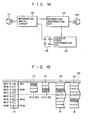
- the circuit 116 transfers the coercive force data to a drive signal circuit 123.
- the circuit 123 outputs a high coercive force write mode signal to the circuit 119 in response to the coercive force data.
- An information write circuit shown in Fig. 5 is, for example, provided in the circuit 119, and a high coercive force write mode signal, i.e., a low level signal is supplied to the transistor Tr.3 of this write circuit. Accordingly, an exciting current of high level flows to the head 111 in accordance with the write data, and the head 111 generates a strong write magnetic field.
- the information of the low coercive force ticket or pass is rewritten by this strong magnetic field. Further, even if the conveyed ticket or pass has a high coercive force, the information is similarly rewritten by the strong magnetic field.
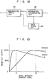
- the read-out output is slightly lowered.
- the graph in Fig. 19 shows this state. In this graph, the ordinate axis indicates the read-out output, and the abscissa axis indicates the write intensity (ampere-turn). However, the 100% mark indicates the read-out output at the optimum write magnetic field intensity.
- the write intensity of the abscissa axis corresponds to the variation in the write current.
- the magnetic flux (read-out output) of either recording medium increases with the increase of the exciting current (write current), and is saturated at a predetermined point.
- the exciting currents Ia, Ib at the saturation point are much larger for the high coercive force recording medium than for the low coercive force recording medium.
- the read-out output decreases. This occurs because the residual magnetic flux of the write information is weakened by the leakage magnetic flux from the portion displaced from the gap of the magnetic head at the writing time, i.e., so-called "recording demagnetization".
- the read-out output decreases. Since the slice level, i.e., readable level of the read-out signal at the reading time is set from 60% to 70% of the ordinary standard output in the present automatic ticket checking apparatus, the above decrease in the read-out output causes no serious problem in practical use.
- a magnetic read-write device which can commonly read and write information on magnetic media of different coercive forces is provided. Therefore, the operating efficiency of the apparatus can be improved.
- the recording medium is not limited to a magnetic medium of 300 Oe or 3,000 Oe, and a magnetic medium which has a coercive force of 600 Oe, 1,200 Oe, ... or more may be used.
Landscapes
- Engineering & Computer Science (AREA)
- Physics & Mathematics (AREA)
- General Physics & Mathematics (AREA)
- Computer Security & Cryptography (AREA)
- Theoretical Computer Science (AREA)
- Devices For Checking Fares Or Tickets At Control Points (AREA)
- Digital Magnetic Recording (AREA)
- Recording Or Reproducing By Magnetic Means (AREA)
- Ticket-Dispensing Machines (AREA)
Abstract
Description
- The present invention relates to a magnetic write device which is provided in a ticket vending machine or ticket checking apparatus used in traffic facilities such as a railway stations, airports, etc., or an automatic transaction apparatus used in banking facilities to write magnetic information.
- Magnetic cards have heretofore been widely used as data input media in automatized equipment such as an automatic ticket checking apparatus or automatic cash dispensing machine or in terminal devices for computers. The magnetic card is formed by coating a base medium, such as a polyester film, with y-Fe203. Oxides such as y-Fe203 and metal powder, or thin metal film which is formed of a composition such as Fe-Co-Ni, have been employed as the magnetic material. Magnetic characteristics such as saturation flux density, coercive force and rectangular ratio become important factors of the magnetic material. The conventional magnetic card has employed a magnetic material which had 1.25 to 1.40 maxwells/centimeter of residual flux density, 300 to 600 Oersted of coercive force, and a rectangular ratio larger than 0.7. It is necessary to consider problems such as demagnetization or a reduction in magnetization when employing such a magnetic card. Particularly in an automatic cash dispensing machine, it is extremely important to solve these problems since the card may be used in place of one's bankbook to carry out a variety of banking transactions.
- The reduction in the magnetization or the demagnetization of the magnetic recording information may be caused by an external magnetic field, such as those generated from speakers of televisions and stereophonic players, electric products such as refrigerators, magnets for toys, or magnets of locks for handbags. Particularly when the conventional magnetic recording medium is in direct contact with a magnet of a toy or the lock of a handbag, the magnetic recording information of the medium can be almost completely demagnetized. Normally, a magnet for a toy or a lock has a DC magnetic field of 500 Oe to 1,000 Oe. When such a DC magnetic field directly contacts a magnetic card which has approx; 600 Oe of coercive force, the magnetic recording information of the card is almost completely demagnetized. In order to avoid such a difficulty, a magnetic recording medium which has a high coercive force such as 2,000 Oe to 3,000 Oe and which is affected very little by the influence of an external magnetic field is used. However, a magnetic recording medium which has such a high coercive force necessitates the application of a high magnetic field at the time of recording information. Further, a magnetic card with a high coercive force becomes expensive. On the other hand, in a conventional automatic ticket checking system used in train stations, magnetic recording media, each of which has a relatively low coercive force such as 300 Oe, are used. It is not necessary to apply a high magnetic field to such media of low coercive force, and when such a high magnetic field is applied to these media, the output level of the recording information of the media is decreased. Even if a magnetic field adapted for the media of low coercive force is applied to the media of high coercive force, its residual flux density is small, and the signal level of the recording information becomes low.
- A ticket which is used for a long period of time such as a pass, a commutation, or season ticket has a possibility of being frequently affected by a strong external magnetic field during such long term use. Accordingly, it is desirable to employ magnetic recording media of high coercive force. However, media of low coercive force are widely used at present, and it would be quite difficult under the present circumstances to introduce magnetic read-write devices using media of high coercive force.
- It is an object of the present invention to provide a magnetic write device which is capable of reading and writing information on magnetic recording media having different coercive forces.
- According to the present invention, there is provided a magnetic write device which comprises means for discriminating the magnitude of coercive force of magnetic recording media and means for controlling the intensity of a magnetic field for recording information in response to the discriminated result of this discriminating means.
- This invention can be more fully understood from the following detailed description when taken in conjunction with the accompanying drawings, in which:
- Fig. 1 is a schematic view of a traffic system which employs a magnetic write device of an embodiment according to the present invention;
- Fig. 2 is a view showing an encode format of a one-way ticket;
- Fig. 3 is a view showing an encode format of a multiple trip ticket;
- Fig. 4 is a view showing an encode format of a pass;
- Figs. 5 to 12 are views respectively showing a variety of information write circuits used for a magnetic write device;
- Fig. 13 is a schematic structural view of a ticket checking apparatus having a magnetic write device of an embodiment according to the present invention;
- Fig. 14 is a block diagram of a data processing section of a ticket checking apparatus shown in Fig. 13;
- Fig. 15 is a plan view of an information write head and a ticket and pass;
- Fig. 16 is a schematic structural view of a ticket checking apparatus of another embodiment;
- Fig. 17 is a plan view showing the relationship between the size detector and the ticket and pass shown in Fig. 16;
- Fig. 18 is a block diagram of another data processing section used for a ticket checking apparatus; and
- Fig. 19 is a graphic view showing the relationship between the coercive force and the read output.
- Fig. 1 schematically shows a traffic system. In this system, a one-way
ticket vending machine 11, a multiple tripticket vending machine 12 and apass vending machine 13 are installed in a station. Thesevending machines way ticket 14, amultiple trip ticket 15 and apass 16, respectively. A magnetic layer coated with a magnetic material is formed on the back surface of each of thetickets pass 16. Various pieces of information are recorded in the magnetic layers of thetickets pass 16 in accordance with the encode formats of Japanese Cybernetics Committee standards. When either the one-way ticket 14,multiple trip ticket 15a orpass 16 is inserted into one of theinlet slots side structures 18R and 18L of anautomatic gate 17, theticket pass 16 is checked by an automatic ticket checking apparatus provided in theside structures 18R and 18L. If theticket pass 16 is proper,gate bars gate 17. - At an arrival station, when the
ticket pass 16 is inserted, for example, into one of theslots side structures automatic gate 21, it is checked by the automatic ticket checking apparatus of theside structure 22R, and, if it is correct,gate bars - As respectively shown in Figs. 2, 3 and 4, information is stored in an encoded format in the
tickets pass 16 used in the above traffic system. In other words, according to the one-way ticket 14 in Fig. 2,first track 31,second track 32 andclock track 33 are formed in the region of the magnetic layer of a rectangle approx. 30 mm x 57 mm. 'Line information, which includes ticketdirection discrimination data 34,month data 35, tensplace date data 36, onesplace date data 37,division data 38,station sequence data 39, section (fare)data 40, acommunication bit 41, aticket type bit 42, aspare bit 43 and aparity bit 44 provided at both ends is stored in thefirst track 31. Another company's line information, which includes ablank bit 45,division data 46,station sequence data 47, section (fare) data '48, ablank bit 49 and aparity bit 50 is stored in thesecond track 32. - On a multiple trip ticket shown in Fig. 3 first and
second tracks clock track 33 are provided, as in the one-way ticket. The same information is stored in thesecond track 32 and theclock track 33 as in the one-way ticket in Fig. 2. However, instead of themonth data 35, tensplace date data 36, onesplace date data 37,division data 38 andstation sequence data 39 of the one-way ticket, the first track of the multiple trip ticket stores an effectiveend month data 51, tens place effectiveend date data 52, ones place effectiveend date data 53, a multiple trip ticket code (coded data for identifying a specific division code as the multiple trip ticket code or part thereof) 54, and multiple trip ticket type data (coded data for indentifying the issuing year of the multiple trip ticket in accordance with station sequence data which is altered every year) 55. On the front surface of the multiple trip ticket ticket fare (section) data is printed. - According to the encode format of the pass shown in Fig. 4, eight magnetic tracks from the
first track 55 to the eighth track 62 are provided in the magnetic layer of 57 mm x 85 mm. The first, second, sixth, seventh and eighth tracks are data tracks which record the discrimination data, and the third track 57 is a clock track. The fourth and fifth tracks 58 and. 59 are tracks to be written by an automatic ticket checking apparatus. These tracks 58 and 59 store error occurrence numbers in case a reading error occurs when information is read from the pass by the automatic ticket checking apparatus. When the number of reading errors exceeds a predetermined number, the pass is considered an information breakdown ticket. - Both high and low coercive force operations are generally provided in the ticket and pass
vending machines exciting coil 72 which has acenter tap 73 is wound on a writemagnetic head 71. Leadwires coil 72 are respectively grounded through the collector-emitter paths of transistors Trl and Tr2. Alead wire 76 of thetap 73 is connected through a resistor Rl to a power source voltage Vcc, and is connected in series through the collector-emitter path of a transistor Tr3 and a resistor R2 to the power voltage Vcc. - In the circuit in Fig. 5, when a low coercive force ticket such as one-
way ticket 14 is issued from the vending machine, a low level signal is inputted to the transistor Tr3, which is, in turn, turned OFF. In this state, high and low level signals are selectively supplied to the bases of the transistors Trl and Tr2 according to a write signal. When the high level signal is, for example, supplied to the base of the transistor Trl and the low level signal is supplied to the transistor Tr2, the transistors Trl and Tr2 are respectively turned "ON" and "OFF". Thus, a current I1 flows to thecoil 72 through the resistor Rl, alead line 76, thecoil 72, alead line 74 and the transistor Trl. In this manner, a weak recordingmagnetic field 77 is induced in thehead 71, thereby recording information on theticket 14 transported to thehead 71 by atransportation system 70. When the transistor Trl is OFF and the transistor Tr2 is ON, thehead 71 generates a recordingmagnetic field 78 of reverse polarity to a recordingmagnetic field 77, thereby recording the information on theticket 14 with the weak magnetic field. - Then, when the vending machine issues a ticket of high coercive force, a high level signal is supplied to the base of the transistor Tr3, which turns it ON. When the transistors Trl and Tr2 are both turned OFF at the
tap 73 in response to the recording information in this state, a current Il+I2 flows through thecoil 72, theline 74 and the collector-emitter path of the transistor Trl. In this case, thehead 71 generates a recording matnetic field stronger than that used when recording the information on a one-way ticket. - In the circuit in Fig. 6, the transistor Tr3 in Fig. 5 is replaced by a switch SW. This switch SW is switched on in response to the issue of a one-way ticket or pass. In other words, when a ticket is recorded with a weak magnetic field, namely, a low coercive force recording mode, the switch SW is opened, while in case of issuing a pass, i.e., when recording the ticket with a strong magnetic field (high coercive force recording mode), the switch SW is closed. The operation of the circuit in Fig. 6 is the same as that of the circuit in Fig. 5.
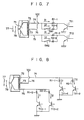
- In a write circuit in Fig. 7, a
center tap 73 of anexciting coil 72 is connected through alead line 76 to a power source voltage Vcc. Alead line 74 connected to one end of thecoil 72 is connected through a resistor Rl-l to the collector of a transistor Trl and is connected in series through a switch SW1 and a resistor R2-1 to the collector of the transistor Trl. Alead line 75 connected to the other end of thecoil 72 is connected to the collector of a transistor Tr2 and is connected in series through a switch SW2 and a resistor R2-2 to the collector of the transistor Tr2. - According to the write circuit in Fig. 7, the switches SW1 and SW2 are respectively opened and closed according to the low or high coercive force recording mode, and the transistors Trl and Tr2 are turned ON or OFF according to the recording information, thereby recording in the low or high coercive force recording mode. In other words, when the switches SW1 and SW2 are opened, the
coil 72 is excited only by the current Il, and information recording is performed with a weak magnetic field by the recording magnetic field on the recording medium, i.e., the magnetic layer of the one-way ticket. When the switches SW1 and SW2 are closed, the exciting current Il+I2 flows through thecoil 72, and the information is recorded on the recording medium of the pass using the strong magnetic field. - In a write circuit in Fig. 8, a
lead line 74 is grounded in parallel through a series circuit of a resistor Rl-l and a transistor Trl-1 and a series circuit of a resistor R2-1 and a transistor Trl-2. Similarly, alead line 75 is grounded in parallel through a series circuit of a resistor Rl-2 and a transistor Tr2-1 and a series circuit of a resistor R2-2 and a transistor Tr2-2. - According to this circuit, a signal corresponding to recording information is supplied to the bases of the transistors Trl-1 and Tr2-1, and a switching signal responsive to low or high coercive force recording mode is supplied to the bases of the transistors Trl-2 and Tr2-2. In other words, the transistors Trl-2 and Tr2-2 are turned OFF in the low coercive force recording mode, the
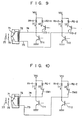
coil 72 is excited by the current I1, and information is recorded on the recording medium with the weak magnetic field. The transistor Trl-2 or Tr2-2 is turned ON in the high coercive force recording mode, and thecoil 72 is excited by the current I1+I2. In this manner, the magnetic head records information on the recording medium using the strong magnetic field. - In a write circuit in Fig. 9, a center tap is not provided at an
exciting coil 72, alead line 74 connected to one end of thecoil 72 is connected through a resistor Rl-l to a power voltage Vcc, and is connected through the collector-emitter path of a transistor Tr3-1 and a resistor R2-1 to a power voltage Vcc. Further, alead line 74 is grounded through the collector-emitter path of a transistor Trl. The power voltage Vcc is connected through a resistor Rl-2 to alead line 75 connected to the other end of thecoil 72 and is connected through a resistor R2-2 and the emitter- collector path of a transistor Tr3-2. Theline 75 is grounded through the collector-emitter path of a transistor Tr2. - According to the circuit in Fig. 9, a recording signal is supplied to the bases of the transistors Trl and Tr2. A low or high coercive force recording mode signal is supplied to the bases of the transistors Tr3-1 and Tr3-2. In other words, the transistors Tr3-l and Tr3-2 are turned OFF in the low coercive force recording mode, and the
coil 72 is excited by the current I1. The transistors Tr3-1 and Tr3-2 are turned ON in the high coercive force recording mode, thecoil 72 is excited by the current Il+I2, and information is recorded on a recording medium with a high coercive force. - In a write circuit in Fig. 10, switches SW1 and SW2 are provided instead of the transistors Tr3-1 and Tr3-2 of the circuit in Fig. 9, and the remainder of the circuit arrangement is the same as the circuit in Fig. 9.
- In a write circuit in Fig. 11, a
lead line 74 connected to one end of anexciting coil 72 is connected through a resistor R to a common contact of a changeover switch SWl, and the first and second contacts of this switch SW1 are respectively connected to power voltages +Vcc and -Vcc. Acenter tap 73 and the other end of anexciting coil 72 are respectively connected throughlead lines - A transistorized circuit of the circuit in Fig. 11 is shown in Fig. 12. In the circuit in Fig. 12, a power voltage +Vcc is connected through a resistor Rl and a transistor Trl-1 to a
lead line 74, and a power voltage -Vcc is connected through a resistor R2 and a transistor Trl-2. Alead line 75 connected to the other end of thecoil 72 is grounded through a transistor Tr2-l and Tr2-2. Alead line 76 connected to acenter tap 73 is grounded through complementary transistors Tr3-l and Tr3-2. - According to the write circuit in Fig. 12, the transistors Trl-1, Tr3-1 and Tr2-1 are selectively turned ON or OFF. In this case, the transistors Trl-2, Tr3-2 and Tr2-2 are turned OFF. In other words, the transistors Trl-1 and Tr3-l are turned ON and the transistor Tr2-l is turned OFF, in the low coercive force recording mode. At this time, a current Il flows from the power voltage +Vcc through a resistor Rl, transistor Trl-l,
coil 72,tap 73,line 76 and transistor Tr3-1. Accordingly, information is recorded on a recording medium with low coercive force. When the transistor Tr3-1 is turned OFF and the transistor Tr2-1 is turned ON, the current I1 flows through resistor Rl, transistor Trl-1,line 74,coil 72,line 75 and transistor Tr2-1. In other words, the current I1 flows through all the coil sections of theexciting coil 72, a strong recordingmagnetic field 77 is generated from amagnetic head 71, and information is recorded on the recording medium with high coercive force. - On the other hand, when the transistors Trl-1, Tr3-1 and Tr2-1 are turned OFF and the transistors Trl-2 and Tr3-2 are turned ON, a current I2 flows through transistor Tr3-2,
line 76,tap 73,coil 72,line 74, transistor Trl-2 and resistor R2. At this time, the recording medium is magnetized by amagnetic field 78 of low intensity, and information is recorded on the recording medium with low coercive force. When the transistor Tr3-l is turned OFF and the transistor Tr2-l is turned ON, a recordingmagnetic field 78 of high density is generated from themagnetic head 71, thereby magnetizing the recording medium and recording the information with high coercive force. - As described above, when the low or high coercive force recording mode is selectively set according to the ticket or pass, predetermined information is recorded on the magnetic layer (recording medium) of a one-way ticket, multiple trip ticket or pass.
- When the one-way ticket, multiple trip ticket or pass thus recorded with the information as described above is inserted into the
inlet slot automatic gate 17, the ticket or pass is checked by the automatic ticket checking apparatus. The ticket checking apparatus is constructed as shown in Fig. 13. In other words, a ticket/pass transporting device 101 hasrollers transport path 102. Amagnetic read device 107 is arranged between therollers device 107 has amagnetic read head 108 and apress roller 109 in contact opposite to each other. Amagnetic write device 110 is arranged between therollers device 110 has amagnetic write head 111 and apress roller 112 in contact opposite to each other. Therollers heads - The output of the
head 108 and the input of thehead 111 are connected to adata processing section 115. This section l15 has, as shown in Fig. 14, aninformation discriminating circuit 116 including an input connected to the output of thehead 108 and a coerciveforce discriminating circuit 117. Thecircuit 116 is constructed to discriminate, for example, the propriety of the information of the pass read by thehead 108 by an ordinary method. The output of thecircuit 117 is connected to the input of a flip-flop 118. The output of the flip-flop 118 is connected to the input of aninformation write circuit 119 together with the output of thecircuit 116. Thecircuit 119 is provided in a ticket vending machine and has a circuit arrangement similar to the information write circuit shown in Figs. 5 to 12. For example, in the write circuit in Fig. 5, the output Q of the flip-flop 118 is supplied to the base of the transistor Tr3, and read information is supplied through thecircuit 116 to the transistors Trl and Tr2. The output of thecircuit 119 is connected to amagnetic head 111 corresponding to thehead 71 in Fig. 5. - When the
pass 16 is introduced between therollers 103 through thetransport path 102 in the above- described automatic ticket checking apparatus, theticket 14 or pass 16 is conveyed by therollers 103 to theread device 109. Thehead 108 of thedevice 109 has eight magnetic head elements provided corresponding to the eighttracks 55 to 62 formed on the pass in Fig. 4, and the information on thepass 16 is read by the eight elements. Since theticket ticket 14 orpass 15a is read by the three elements of one side of the eight elements. - The information read by the
head 108 is inputted to thecircuit 116, which transfers the coercive force data of the input information into thecircuit 117. In the case of the one-way ticket, the coercive force data may be substituted for theticket type bit 42 in Fig. 2 or may use thespare bit 43. In the case of the multiple trip ticket, the multipletrip ticket code 54 is used as the coercive force data, and in the case of the pass, the coercive force data is stored in any of the data tracks 55, 56, 60, 61 and 62. - The
circuit 117 discriminates whether the inputted coercive force data is high or low, and supplies a set signal or reset signal to the flip-flop 118 according to the discriminated result. When the coercive force data represents, for example, the high coercive force with "1" and the low coercive force with "0", thecircuit 117 outputs the set signal with the data "1" and the reset signal with the data "0". When the flip-flop 118 supplies, when set, an output Q to thecircuit 119, the transistor Tr3 of the write circuit in Fig. 5 is turned ON, and thecircuit 119 is set to the high coercive force recording mode. When the flip-flop 118 is reset, the transistor Tr3 is turned OFF, and thecircuit 119 is set to the low coercive force recording mode. - On the other hand, the circuit l16 discriminates the information of the
ticket circuit 116 discriminates, for example, the effective section or effective term. When thecircuit 116 discriminates the proper data, it supplies, for example, a gate open signal to a gate driving device (not shown). When an error exists in the data of thepass 16 in this discriminating operation, thecircuit 116 generates number-of-errors data. The ticket or pass is conveyed by therollers device 107 to thedevice 110. As shown in Fig. 15, theticket guide surface 120 to thedevice 110, but since the ticket or pass is inserted in an arbitrary direction into the ticket checking apparatus, the ticket or pass may be conveyed in either the normal or reverse directions, as shown by FT, RT, FP and RP in Fig. 15. Thewrite head 111 has eight write head elements WH1 to WH8, and four read head elements RH1, RH3, RH6 and RH8 for reading a clock. When theticket head 111, the clock track of theticket ticket circuit 119 based on the directional data stored on the track of theticket circuit 119 writes ticket or pass information transferred from thecircuit 116 on the ticket or pass synchronously with the clock of the clock track. In this case, the normal direction ticket FT is written by the elements WH2 and WH3, and the reverse direction ticket RT is written by the elements WH1 and VJH2. Similarly, the normal direction pass FP is written by the elements WH1 and WH2, and WH5 to WH8, and the reverse direction pass PR is written by the elements WH1 to WH5 and WH7 and WH8. - Write information is ticket or pass information which is discriminated by the
circuit 116 and update data, and when such information is supplied, for example, to the bases of the transistors Trl and Tr2 of thecircuit 119 in Fig. 5, the information of the ticket or pass is all rewritten. - The elements WH1 to WH3, RH1 and RH3 of the
head 111 slidably contact theticket pass 16. Accordingly, the elements WH1 to WH3 and RH1 and RH3 are worn more than the elements WH4 to WH8 and RH6. In order to compensate this, the head elements are symmetrically arranged about a center (shown by a one-dotted chain line) in thewrite head 111, and thewrite head 111 is constructed so that, when thehead 111 is worn irregularly at one side, it may be turned at 180° around the (one-dotted chain line) center. In this manner, one-side wear of the head can be corrected, and the lifetime of the head can be substantially prolonged. This can also be applied to the readhead 108. - In the embodiments described above, description has been given using the one-
way ticket 14 as a low coercive force ticket and themultiple trip ticket 15 and pass 16 as a high coercive force ticket. However, the low and high coercive force passes may be used. When the high coercive force pass is used, the pass is not reduced in magnetization nor demagnetized by the external magnetic field. Accordingly, if almost no error occurs in reading the high coercive force pass, it is not necessary to record data of the number of reading errors. Consequently, only information on the pass size needs to be written for the low coercive force magnetic layer. On the other hand, in the case of theticket multiple trip ticket 15a is determined to be effective by thecircuit 116, the effectiveend month data 51, tens place effectiveend date data 52, ones place effectiveend date data 53, multipletrip ticket code 54 andticket type data 55 of themultiple trip ticket 15a must be rewritten to correspond to the data 62 to 66 of the one-way ticket 14. Therefore, in the case of the ticket size, the information may be written only for the high coercive force ticket. From this, the write circuit may be set to either the high or low coercive force recording mode by discriminating the ticket size. - Fig. 15 shows an automatic ticket checking apparatus having a ticket size discriminating function. In Fig. 15, a
size detector 121 is arranged at the inlet side of atransport path 102. As shown in Fig. 17, thisdetector 121 has fourphotointerrupters 121a to 121d, each of which has a photoemissive element (light emitting diode) LED and a photoelectric element (photodiode) PD arranged opposite to each other with thepath 102 as a boundary. - When the
pass 16 is conveyed to thedetector 121 while being aligned by an aligningguide 122, all fourphotointerrupters 121a to 121d of thedetector 121 simultaneously operate. At this time, thedetector 121 detects the pass size. However, when theticket detector 121, a plurality of photointerrupters do not operate simultaneously. In other words, in Fig. 17, thephotointerrupter 121d initially operates, and thephotointerrupter 121b then operates after the operation of thephotointerrupter 121d is released. Accordingly, in the case of theticket photointerrupter detector 121 detects the ticket size. When the detection signal of thedetector 121 is inputted to adata processing section 115, thecircuit 116 of thesection 115 determines the pass size and ticket size. - The ticket or pass thus discriminated in size is conveyed to the
device 107, thehead 108 reads the information of the ticket or pass, and the information is transferred to thesection 115. Thesection 115 determines whether the conveyed ticket or pass is a low or high coercive force ticket. The write mode is set in the circuit l19 based on the discriminated coercive force and size results. In other words, when the low coercive force ticket is discriminated by the pass size, the low coercive force recording mode is set for the pass, and when the high coercive force ticket is discriminated in the ticket size, the high coercive force recording mode is set for the ticket. - When the ticket or pass is conveyed to the
device 110, thehead 111 records information on the ticket or pass in response to the set recording mode. In other words, when the conveyed ticket is a low coercive force ticket, the elements WH4 and WH5 in Fig. 15 are set to the low coercive force exciting state. When the conveyed ticket is a high coercive force ticket, i.e., a multiple trip ticket, the elements WH1 to WH3 are set to a high coercive force exciting state. Since the high coercive force ticket and low coercive force ticket, i.e., one-way tickets do not need data writing, thedevice 110 is not operated. - In the case of the embodiment in Fig. 16, central head elements WH4 and WH5 of the
write head 111 may be composed of low coercive force magnetic heads, and side head elements WH6 and WH8 may be composed of high coercive force magnetic heads. In this case, thecircuit 119 does not necessitate the exciting current switching circuit or coil switching circuit. Accordingly, thecircuit 119 may be constructed with a simple circuit. - In the embodiments described above, information is recorded on the low coercive force ticket with low coercive force, and is recorded on the high coercive force ticket with high coercive force. In an embodiment in Fig. 18, when information is recorded on the tickets, it is recorded with the coercive force of the ticket having the maximum coercive force among the tickets having different coercive forces. The low coercive force of the ticket and pass is 300 Oe, and the high coercive force is 3,000 Oe. In the embodiment described above, information is rewritten with a high coercive force of 3,000 Oe in all the low coercive force tickets and passes, and the high coercive force ticket and pass are written with the same high coercive force. In other words, when information to be read is inputted to the
circuit 116 in Fig. 18, thecircuit 116 transfers the coercive force data to adrive signal circuit 123. Thecircuit 123 outputs a high coercive force write mode signal to thecircuit 119 in response to the coercive force data. An information write circuit shown in Fig. 5 is, for example, provided in thecircuit 119, and a high coercive force write mode signal, i.e., a low level signal is supplied to the transistor Tr.3 of this write circuit. Accordingly, an exciting current of high level flows to thehead 111 in accordance with the write data, and thehead 111 generates a strong write magnetic field. The information of the low coercive force ticket or pass is rewritten by this strong magnetic field. Further, even if the conveyed ticket or pass has a high coercive force, the information is similarly rewritten by the strong magnetic field. When the low coercive force ticket is written with the same magnetic field as the high coercive force ticket, the read-out output is slightly lowered. The graph in Fig. 19 shows this state. In this graph, the ordinate axis indicates the read-out output, and the abscissa axis indicates the write intensity (ampere-turn). However, the 100% mark indicates the read-out output at the optimum write magnetic field intensity. The write intensity of the abscissa axis corresponds to the variation in the write current. According to this graph, when the exciting current is increased to magnetize both the low coercive force recording medium of 300 Oe and the high coercive force recording medium of 3,000 Oe, the magnetic flux (read-out output) of either recording medium increases with the increase of the exciting current (write current), and is saturated at a predetermined point. The exciting currents Ia, Ib at the saturation point are much larger for the high coercive force recording medium than for the low coercive force recording medium. When the exciting current exceeds the saturation point, the read-out output decreases. This occurs because the residual magnetic flux of the write information is weakened by the leakage magnetic flux from the portion displaced from the gap of the magnetic head at the writing time, i.e., so-called "recording demagnetization". - When the information is written on the low coercive force recording medium with a strong magnetic field as described above, the read-out output decreases. Since the slice level, i.e., readable level of the read-out signal at the reading time is set from 60% to 70% of the ordinary standard output in the present automatic ticket checking apparatus, the above decrease in the read-out output causes no serious problem in practical use.
- According to the present invention as described above, a magnetic read-write device which can commonly read and write information on magnetic media of different coercive forces is provided. Therefore, the operating efficiency of the apparatus can be improved.
- It is preferred to construct the information read device so as to generate the read-out output at a constant level irrespective of the read-out output from the low or high coercive force ticket. The recording medium is not limited to a magnetic medium of 300 Oe or 3,000 Oe, and a magnetic medium which has a coercive force of 600 Oe, 1,200 Oe, ... or more may be used.
Claims (11)
Applications Claiming Priority (2)
| Application Number | Priority Date | Filing Date | Title |
|---|---|---|---|
| JP66255/82 | 1982-04-22 | ||
| JP6625582A JPS58185008A (en) | 1982-04-22 | 1982-04-22 | Recorder of magnetic information |
Publications (4)
| Publication Number | Publication Date |
|---|---|
| EP0092763A2 true EP0092763A2 (en) | 1983-11-02 |
| EP0092763A3 EP0092763A3 (en) | 1987-01-07 |
| EP0092763B1 EP0092763B1 (en) | 1990-03-14 |
| EP0092763B2 EP0092763B2 (en) | 1993-09-29 |
Family
ID=13310565
Family Applications (1)
| Application Number | Title | Priority Date | Filing Date |
|---|---|---|---|
| EP19830103727 Expired - Lifetime EP0092763B2 (en) | 1982-04-22 | 1983-04-18 | Magnetic write device |
Country Status (3)
| Country | Link |
|---|---|
| EP (1) | EP0092763B2 (en) |
| JP (1) | JPS58185008A (en) |
| DE (1) | DE3381327D1 (en) |
Cited By (6)
| Publication number | Priority date | Publication date | Assignee | Title |
|---|---|---|---|---|
| EP0903682A2 (en) * | 1997-09-19 | 1999-03-24 | Sankyo Seiki Mfg. Co. Ltd. | Magnetic card reader and method for determining the coercive force of a magnetic card therein |
| EP0978797A2 (en) * | 1998-08-03 | 2000-02-09 | Neuron Corporation | Magnetic card recording/reproducing apparatus and method |
| EP1024452A2 (en) * | 1998-11-24 | 2000-08-02 | Sankyo Seiki Mfg. Co. Ltd. | Recording medium detection |
| EP1059601A2 (en) * | 1999-06-09 | 2000-12-13 | Sankyo Seiki Mfg. Co. Ltd. | Magnetism detecting apparatus and magnetic material identifying apparatus |
| EP1396848A2 (en) * | 2002-08-28 | 2004-03-10 | Omron Corporation | Device for determining coercive force of magnetic recording medium |
| EP2717267A4 (en) * | 2011-05-24 | 2016-01-06 | Nidec Sankyo Corp | Method for determining coercivity of magnetic recording medium |
Families Citing this family (2)
| Publication number | Priority date | Publication date | Assignee | Title |
|---|---|---|---|---|
| JP2006293911A (en) * | 2005-04-14 | 2006-10-26 | Toshiba Corp | Verification system of automatic ticket gate and verification system of automatic ticket gate system |
| JP5061723B2 (en) * | 2007-05-25 | 2012-10-31 | 沖電気工業株式会社 | Magnetic recording device |
Citations (3)
| Publication number | Priority date | Publication date | Assignee | Title |
|---|---|---|---|---|
| GB1212502A (en) * | 1966-12-10 | 1970-11-18 | Emi Ltd | Improvements relating to cards capable of breaking an authenticity code |
| US3790754A (en) * | 1972-08-04 | 1974-02-05 | Burroughs Machines Ltd | Security access medium |
| US3803634A (en) * | 1971-06-25 | 1974-04-09 | Magnetic Printing Co Ltd | Magnetic pattern printing method |
-
1982
- 1982-04-22 JP JP6625582A patent/JPS58185008A/en active Granted
-
1983
- 1983-04-18 DE DE8383103727T patent/DE3381327D1/en not_active Expired - Lifetime
- 1983-04-18 EP EP19830103727 patent/EP0092763B2/en not_active Expired - Lifetime
Patent Citations (3)
| Publication number | Priority date | Publication date | Assignee | Title |
|---|---|---|---|---|
| GB1212502A (en) * | 1966-12-10 | 1970-11-18 | Emi Ltd | Improvements relating to cards capable of breaking an authenticity code |
| US3803634A (en) * | 1971-06-25 | 1974-04-09 | Magnetic Printing Co Ltd | Magnetic pattern printing method |
| US3790754A (en) * | 1972-08-04 | 1974-02-05 | Burroughs Machines Ltd | Security access medium |
Non-Patent Citations (1)
| Title |
|---|
| IBM TECHNICAL DISCLOSURE BULLETIN, vol. 7, no. 6, November 1964, page 500, Yorktown Heights, US; R.E. BRAUN: "Scanned recording by utilizing the coercivity characteristics of a recording media" * |
Cited By (12)
| Publication number | Priority date | Publication date | Assignee | Title |
|---|---|---|---|---|
| EP0903682A2 (en) * | 1997-09-19 | 1999-03-24 | Sankyo Seiki Mfg. Co. Ltd. | Magnetic card reader and method for determining the coercive force of a magnetic card therein |
| EP0903682A3 (en) * | 1997-09-19 | 2001-01-17 | Sankyo Seiki Mfg. Co. Ltd. | Magnetic card reader and method for determining the coercive force of a magnetic card therein |
| EP0978797A2 (en) * | 1998-08-03 | 2000-02-09 | Neuron Corporation | Magnetic card recording/reproducing apparatus and method |
| EP0978797A3 (en) * | 1998-08-03 | 2002-05-22 | Neuron Corporation | Magnetic card recording/reproducing apparatus and method |
| EP1024452A2 (en) * | 1998-11-24 | 2000-08-02 | Sankyo Seiki Mfg. Co. Ltd. | Recording medium detection |
| EP1024452A3 (en) * | 1998-11-24 | 2002-02-27 | Sankyo Seiki Mfg. Co. Ltd. | Recording medium detection |
| US6574058B1 (en) | 1998-11-24 | 2003-06-03 | Sankyo Seiki Mfg. Co., Ltd. | Recording medium detecting apparatus for distinguishing between a recording medium having a relatively high coercivity or a relatively low coercivity |
| EP1059601A2 (en) * | 1999-06-09 | 2000-12-13 | Sankyo Seiki Mfg. Co. Ltd. | Magnetism detecting apparatus and magnetic material identifying apparatus |
| EP1059601A3 (en) * | 1999-06-09 | 2002-05-15 | Sankyo Seiki Mfg. Co. Ltd. | Magnetism detecting apparatus and magnetic material identifying apparatus |
| EP1396848A2 (en) * | 2002-08-28 | 2004-03-10 | Omron Corporation | Device for determining coercive force of magnetic recording medium |
| EP1396848A3 (en) * | 2002-08-28 | 2005-11-02 | Omron Corporation | Device for determining coercive force of magnetic recording medium |
| EP2717267A4 (en) * | 2011-05-24 | 2016-01-06 | Nidec Sankyo Corp | Method for determining coercivity of magnetic recording medium |
Also Published As
| Publication number | Publication date |
|---|---|
| JPS58185008A (en) | 1983-10-28 |
| EP0092763A3 (en) | 1987-01-07 |
| EP0092763B1 (en) | 1990-03-14 |
| EP0092763B2 (en) | 1993-09-29 |
| JPH0438045B2 (en) | 1992-06-23 |
| DE3381327D1 (en) | 1990-04-19 |
Similar Documents
| Publication | Publication Date | Title |
|---|---|---|
| KR970011124B1 (en) | Magnetic recording transfer method of toll road ticket and digital recording and reproducing circuit of magnetic card | |
| US3986205A (en) | Dual particle population magnetic recording medium | |
| US5767495A (en) | Reduced-power magnetic transducer system utilizing a magnetoresistive head | |
| EP0092763A2 (en) | Magnetic write device | |
| US5650606A (en) | Accurate read/write head for preventing credit card alteration and counterfeiting of debit cards | |
| US3874586A (en) | Information-carrying article and reading apparatus and method | |
| US6513713B1 (en) | Magnetism detecting apparatus and magnetic material identifying apparatus using the same | |
| US2941190A (en) | Magnetic selecting system | |
| US3368208A (en) | Information carriers for magnetic destination recording in conveying systems | |
| EP0128535B1 (en) | Value-rated magnetic card writing and reading system, particularly for public telephony | |
| US3855619A (en) | Magnetic card readout machine and cards therefor | |
| EP1256094B1 (en) | Ticket provided with a magnetic layer, and a corresponding apparatus for ticket emission, validation and inspection | |
| JPH03229391A (en) | Discriminating method for coercive force of magnetic ticket form | |
| JPH10255211A (en) | Magnetic card recording and reproducing device and magnetic card | |
| JPH117502A (en) | Magnetic card processor | |
| JP2654047B2 (en) | Magnetic information writing device for read / write composite magnetic head | |
| JP2001093111A (en) | Magnetic head and information recording/reproducing device using the same | |
| JPH06266934A (en) | Magnetic information reader | |
| JPH10149502A (en) | Information processor | |
| JPH06286368A (en) | Record carrier card and device for determine its genuineness | |
| JPH10334199A (en) | Illegal use preventing method for magnetic card and magnetic card reader and writer device | |
| JPS6151276A (en) | Ticket reader | |
| JP2000260112A (en) | Device and method for detecting recording medium | |
| JPH05189734A (en) | Ac transcribing head | |
| Franklin | Factors influencing the applications of magnetic tape recording to digital computers |
Legal Events
| Date | Code | Title | Description |
|---|---|---|---|
| PUAI | Public reference made under article 153(3) epc to a published international application that has entered the european phase |
Free format text: ORIGINAL CODE: 0009012 |
|
| 17P | Request for examination filed |
Effective date: 19830513 |
|
| AK | Designated contracting states |
Designated state(s): DE FR GB |
|
| RAP1 | Party data changed (applicant data changed or rights of an application transferred) |
Owner name: KABUSHIKI KAISHA TOSHIBA |
|
| PUAL | Search report despatched |
Free format text: ORIGINAL CODE: 0009013 |
|
| AK | Designated contracting states |
Kind code of ref document: A3 Designated state(s): DE FR GB |
|
| 17Q | First examination report despatched |
Effective date: 19880307 |
|
| GRAA | (expected) grant |
Free format text: ORIGINAL CODE: 0009210 |
|
| AK | Designated contracting states |
Kind code of ref document: B1 Designated state(s): DE FR GB |
|
| REF | Corresponds to: |
Ref document number: 3381327 Country of ref document: DE Date of ref document: 19900419 |
|
| ET | Fr: translation filed | ||
| PLBE | No opposition filed within time limit |
Free format text: ORIGINAL CODE: 0009261 |
|
| PLBI | Opposition filed |
Free format text: ORIGINAL CODE: 0009260 |
|
| 26 | Opposition filed |
Opponent name: GAO GESELLSCHAFT FUER AUTOMATION UND ORGANISATION Effective date: 19901214 |
|
| 26N | No opposition filed | ||
| PLAA | Information modified related to event that no opposition was filed |
Free format text: ORIGINAL CODE: 0009299DELT |
|
| PLAB | Opposition data, opponent's data or that of the opponent's representative modified |
Free format text: ORIGINAL CODE: 0009299OPPO |
|
| R26 | Opposition filed (corrected) |
Opponent name: GAO GESELLSCHAFT FUER AUTOMATION UND ORGANISATION Effective date: 19901214 |
|
| PUAH | Patent maintained in amended form |
Free format text: ORIGINAL CODE: 0009272 |
|
| STAA | Information on the status of an ep patent application or granted ep patent |
Free format text: STATUS: PATENT MAINTAINED AS AMENDED |
|
| 27A | Patent maintained in amended form |
Effective date: 19930929 |
|
| AK | Designated contracting states |
Kind code of ref document: B2 Designated state(s): DE FR GB |
|
| ET3 | Fr: translation filed ** decision concerning opposition | ||
| PGFP | Annual fee paid to national office [announced via postgrant information from national office to epo] |
Ref country code: GB Payment date: 19970409 Year of fee payment: 15 Ref country code: FR Payment date: 19970409 Year of fee payment: 15 |
|
| PGFP | Annual fee paid to national office [announced via postgrant information from national office to epo] |
Ref country code: DE Payment date: 19970428 Year of fee payment: 15 |
|
| PG25 | Lapsed in a contracting state [announced via postgrant information from national office to epo] |
Ref country code: GB Free format text: LAPSE BECAUSE OF NON-PAYMENT OF DUE FEES Effective date: 19980418 |
|
| PG25 | Lapsed in a contracting state [announced via postgrant information from national office to epo] |
Ref country code: FR Free format text: THE PATENT HAS BEEN ANNULLED BY A DECISION OF A NATIONAL AUTHORITY Effective date: 19980430 |
|
| GBPC | Gb: european patent ceased through non-payment of renewal fee |
Effective date: 19980418 |
|
| PG25 | Lapsed in a contracting state [announced via postgrant information from national office to epo] |
Ref country code: DE Free format text: LAPSE BECAUSE OF NON-PAYMENT OF DUE FEES Effective date: 19990202 |
|
| REG | Reference to a national code |
Ref country code: FR Ref legal event code: ST |