EP0084366B1 - Coke oven chamber door - Google Patents
Coke oven chamber door Download PDFInfo
- Publication number
- EP0084366B1 EP0084366B1 EP83100326A EP83100326A EP0084366B1 EP 0084366 B1 EP0084366 B1 EP 0084366B1 EP 83100326 A EP83100326 A EP 83100326A EP 83100326 A EP83100326 A EP 83100326A EP 0084366 B1 EP0084366 B1 EP 0084366B1
- Authority
- EP
- European Patent Office
- Prior art keywords
- door
- steel plate
- coke oven
- steel plates
- plug
- Prior art date
- Legal status (The legal status is an assumption and is not a legal conclusion. Google has not performed a legal analysis and makes no representation as to the accuracy of the status listed.)
- Expired
Links
Images
Classifications
-
- C—CHEMISTRY; METALLURGY
- C10—PETROLEUM, GAS OR COKE INDUSTRIES; TECHNICAL GASES CONTAINING CARBON MONOXIDE; FUELS; LUBRICANTS; PEAT
- C10B—DESTRUCTIVE DISTILLATION OF CARBONACEOUS MATERIALS FOR PRODUCTION OF GAS, COKE, TAR, OR SIMILAR MATERIALS
- C10B25/00—Doors or closures for coke ovens
- C10B25/02—Doors; Door frames
- C10B25/06—Doors; Door frames for ovens with horizontal chambers
Definitions
- the invention relates to a coke oven chamber door with a heat-resistant stopper, which consists of an outer door body plate and inner steel plates which are slidably arranged for thermal insulation at one end.
- a heat-resistant stopper which consists of an outer door body plate and inner steel plates which are slidably arranged for thermal insulation at one end.
- Such furnace chamber doors are used in particular for coke ovens, the furnace chamber walls of which are provided with heating trains which, compared to the design in flame furnaces with quenched furnace filling and moved back first heating trains, have heating trains moved forward and a mechanical leveling of the furnace filling.
- the refractory stopper not only serves to reduce the heat emission of the door plate, which is usually made of cast iron, to the extent that the door body constructions cannot bend, but the stopper is also intended to withstand the preheating stress caused by the laying of the first heating cables Reduce the furnace, namely the furnace heads and in particular the anchor positions located there, by keeping the glowing coke furnace far back.
- the stopper is made of refractory material, e.g. B. in the form of a resting on a lower stone holder and held by lateral stone holders, or made of molded blocks that are screwed to the door body plate, for example.
- the first heating draft of the chamber walls is usually behind an outward-facing wall made of preferably semi-acidic stones, the outside of which is supported on the anchor stands by a layer of heat-insulating material and carries the usually interchangeable door frame.
- the inside of the refractory stopper material protrudes into the furnace chamber up to the first heating draft.
- the sealing joint is removed from the heat of the first heating train and the coke cake.
- the thermal expansion of the coating that occurs during the coking process can be compensated for by using metal plates as the coating. In this way, the footprint of the door plug becomes a heating surface and can result in a better cooking of the head parts of the stove.
- An air or gas cushion can be formed between the door plugs and the steel plates.
- the poor thermal conductivity of this closed air or gas space can be used excellently for thermal insulation.
- the distance between the door body and steel plates can be varied depending on the permissible surface temperature of the door body.
- the steel plates are stiffened in a T-shape and are located one above the other at the ends. The steel plates can freely expand at these ends.
- the steel plates should not be longer than 1 m in the case of 4 m high furnaces, the steel plate length decreasing by one tenth of the change in height with each increase in the furnace height. For a 7 m furnace, this would result in a maximum length of steel plates of 0.7 m.
- the operational availability of this door system is much lower than with conventional door plugs due to recurring faults. The damage is concentrated on the lower plate area.
- the invention has for its object to adapt such door plugs to the rough coking plant.
- the invention is based on the idea that the cause of the various damage is the fact that when the door is pulled off - in particular in the manually controlled sequence - the doors are partially pulled off and subsequently lowered, so that the bottom steel plate rests on the sole touches down. At this point, the entire weight rests on the steel plate, which is then strongly deformed together with its holder. In the further work process, the door is pulled forward, the lowest steel plate then slides over the sole and comes in front of the door frame, which is higher than the sole. As a result, the bottom plate is bent forward and torn out of the holder.
- the bottom steel plate has a fixed point at the lower end and is slidably mounted at the upper end for thermal expansion.
- Another advantage is the double function of the upper bracket for the lowest steel plate. According to the original concept, this bracket forms a longitudinally movable bearing for the steel plate above. According to the invention, this bracket also forms a longitudinally displaceable bearing for the lowest steel plate.
- a common movable bearing is provided for two adjacent steel plates.
- the ends of the steel plates facing away from the movable bearing have common mounts with the adjoining steel plates, so that two steel plates are locked on each of these brackets.
- the top steel plate of the oven door is optionally arranged using separate brackets and movable bearings so that the steel plate end located at the top of the door is locked and the thermal expansion of the steel plate or the associated change in length affects downwards. All steel plates are arranged so that the lower end of an upper steel plate overlaps the upper end of an underlying steel plate.
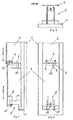
- the known coke oven chamber door is provided with a door body 1.
- a plug 2 is located on the door body 1.
- the coke oven chamber door projects with the stopper 2 into the coke oven chamber, while the door head 1 lies against the outside of the door frame.
- sealing strips not shown, provide an adequate seal.
- the sealing strips consist, for example, of profiled iron.
- the stopper 2 forms a hollow body and, as a hollow body, a gas collecting space through which the gas obtained during coking can rise to a gas collecting space arranged in the head of the coke oven or to a riser pipe in the ceiling area of the coke oven.
- the plug 2 is composed of a number of sections, of which the sections 3 and 4 are shown in FIGS. 1 and 2. Each section 3 and 4 has a steel plate 5. The individual steel plates 5 overlap, from top to bottom so that the lower end of an upper steel plate 5 overlaps the upper end of a subsequent lower steel plate 5.
- the steel plates 5 are provided with tabs at each end.
- the tabs on the upper steel sheet end serve to lock the associated steel sheet end, while the tabs on the lower steel sheet end are intended to enable longitudinally displaceable storage for thermal expansion of the sheets downwards.
- the tab of section 4 at the lower end of sheet steel is designated 6, that at the upper end of section 3 with 7 and that at the lower end of section 3 with 8.
- the tab 6 is guided with bolts 9 in the tab 7 so as to be longitudinally displaceable. For this purpose, there is a sufficient section for the thermal expansion of the steel sheet 5 of section 4 between the tabs 6 and 7.
- the tab 7 is in turn on a bracket 10 attached to the door body 1. Between the bracket 10 and the tab 7 there is a schematically indicated bolt or screw connection which fixes the upper end of section 3. The same arrangement exists at the upper end of section 4. At the lower end of section 3, a bracket 11 enables longitudinally displaceable storage for thermal expansion. The bracket 11 is fastened to the door frame and guides the lower end of the section 3 with a bolt 12 which is displaceable longitudinally in the bracket 8.
- the existing between the steel plates 5 and the door body 1 forms a vertical gas plenum through which the gaseous coking products are advantageously derived and fed to the upper gas plenum and the riser. Due to the resulting favorable gas pressure conditions, the pressure structure on the door frame or on the coke oven door as a whole is so favorable to the respective outer atmosphere that emissions on the coke oven doors are prevented with conventional sealing strips.
- the steel plates 5 have a high thermal conductivity.
- the high thermal conductivity also results in the supply of heat via the steel plates 5. This effect allows the plate to protrude less than 100 mm into the furnace chamber. This is equivalent to an increase in the usable oven volume while the head sections are cooked consistently.
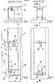
- the coke oven chamber door according to FIGS. 4 to 7 differs from the coke oven chamber door according to FIGS. 1 to 3 both by a different suspension of the sections 3 and 4 in the connecting area 13 and by a different arrangement at the foot of the plug 2.
- the latter area is marked with 14.
- the tab 7 is provided at the connection point with the bracket 10 with an elongated hole 15, which enables a thermal expansion of the steel plate 5 in the longitudinal direction of the door within the scope of section 3.
- the connection between the tab 7 and the bracket 10 is made by a bolt arranged in the bracket 10 and shown schematically, which slides in the slot 15.
- the console 16 extends essentially to the steel plate 5 of section 3 and is on the bottom connected to a slide shoe 17.
- section 3 is stiffened with the bracket 16 and is additionally protected against damage by the sliding shoe 17. In this way it is achieved that neither damage to the door structure nor to the frame or the sole stones can occur when inserting the door, regardless of the operation of the door operating machines.
Landscapes
- Chemical & Material Sciences (AREA)
- Engineering & Computer Science (AREA)
- Materials Engineering (AREA)
- Oil, Petroleum & Natural Gas (AREA)
- Organic Chemistry (AREA)
- Coke Industry (AREA)
Description
Die Erfindung betrifft eine Koksofenkammertür mit einem hitzebeständigen Stopfen, der aus einer außenliegenden Türkörperplatte und innenliegenden Stahlplatten besteht, die zur Wärmedämmung mit einem Ende verschiebbar angeordnet sind. Derartige Ofenkammertüren dienen insbesondere für Koksöfen, deren Ofenkammerwände mit Heizzügen versehen sind, welche gegenüber der Bauart in Flammenöfen mit abgeschreckter Ofenfüllung und zurückverlegten ersten Heizzügen vorverlegte Heizzüge und eine maschinelle Planierung der Ofenfüllung aufweisen. Bei den hierfür bestimmten Kammertüren dient der feuerfeste Stopfen nicht nur dazu, die Wärmeabgabe der zumeist aus Gußeisen bestehenden Türplatte nach außen soweit zu vermindern, daß die Türkörperkonstruktionen sich nicht verbiegen können, sondern der Stopfen soll auch die durch die Verlegung der ersten Heizzüge bedingte Vorwärmebeanspruchung des Ofens, nämlich der Ofenköpfe und insbesondere der dort liegenden Ankerstände dadurch reduzieren, daß er den glühenden Koksofen entsprechend weit zurückhält.The invention relates to a coke oven chamber door with a heat-resistant stopper, which consists of an outer door body plate and inner steel plates which are slidably arranged for thermal insulation at one end. Such furnace chamber doors are used in particular for coke ovens, the furnace chamber walls of which are provided with heating trains which, compared to the design in flame furnaces with quenched furnace filling and moved back first heating trains, have heating trains moved forward and a mechanical leveling of the furnace filling. With the chamber doors intended for this purpose, the refractory stopper not only serves to reduce the heat emission of the door plate, which is usually made of cast iron, to the extent that the door body constructions cannot bend, but the stopper is also intended to withstand the preheating stress caused by the laying of the first heating cables Reduce the furnace, namely the furnace heads and in particular the anchor positions located there, by keeping the glowing coke furnace far back.
Bei bekannten Koksofentürkonstruktionen für derartige Koksöfen besteht der Stopfen aus feuerfestem Material, z. B. in Form einer auf einem unteren Steinhalter ruhenden und von seitlichen Steinhaltern festgehaltenen Aufmauerung oder aus Formsteinen, die mit der Türkörperplatte beispielsweise verschraubt sind. Der jeweils erste Heizzug der Kammerwände liegt zumeist hinter einer nach außen weisenden Mauerung aus vorzugsweise halbsauren Steinen, deren Außenseite über eine Schicht aus wärmedämmendem Werkstoff auf den Ankerständen abgestützt ist und den in der Regel auswechselbaren Türrahmen trägt. Die Innenseite des feuerfesten Stopfenmaterials steht bei geschlossener Türe bis zum ersten Heizzug in die Ofenkammer vor. Dadurch ist die Dichtungsfuge der Wärmeeinwirkung des ersten Heizzuges und des Kokskuchens entzogen. Zur Beschleunigung der Ausgarung der Kopfpartien des Koksofens und demzufolge zur Vergleichmäßigung des Kokskuchens ist nach der DE-OS 3 000 161 vorgeschlagen worden, den Stopfen an seiner Ofenseite mit einem Belag zu versehen, der gegenüber dem Stopfenwerkstoff eine höhere Wärmeleitfähigkeit aufweist. Durch den Belag werden die Gesamtabmessungen des Türstopfens nicht verändert, so daß der Türstopfen ohne Belag um die in der gleichen Richtung liegende Belagstärke reduziert ist.In known coke oven door constructions for such coke ovens, the stopper is made of refractory material, e.g. B. in the form of a resting on a lower stone holder and held by lateral stone holders, or made of molded blocks that are screwed to the door body plate, for example. The first heating draft of the chamber walls is usually behind an outward-facing wall made of preferably semi-acidic stones, the outside of which is supported on the anchor stands by a layer of heat-insulating material and carries the usually interchangeable door frame. When the door is closed, the inside of the refractory stopper material protrudes into the furnace chamber up to the first heating draft. As a result, the sealing joint is removed from the heat of the first heating train and the coke cake. In order to accelerate the cooking of the head parts of the coke oven and consequently to make the coke cake more uniform, it has been proposed according to DE-OS 3 000 161 to provide the stopper on its oven side with a coating which has a higher thermal conductivity than the stopper material. The covering does not change the overall dimensions of the door stopper, so that the door stopper without covering is reduced by the covering thickness lying in the same direction.
Die während des Verkokungsvorganges auftretende Wärmedehnung des Belages läßt sich durch Verwendung von Metallplatten als Belag kompensieren. Auf diese Weise wird die Standfläche des Türstopfens zur Heizfläche, und kann eine bessere Ausgarung der Kopfpartien des Ofenbesatzes bewirken.The thermal expansion of the coating that occurs during the coking process can be compensated for by using metal plates as the coating. In this way, the footprint of the door plug becomes a heating surface and can result in a better cooking of the head parts of the stove.
Zwischen den Türstopfen und den Stahlplatten kann ein Luft- bzw. Gaspolster gebildet werden. Die schlechte Wärmeleitfähigkeit dieses abgeschlossenen Luft- oder Gasraumes läßt sich zur Wärmedämmung hervorragend nutzen. Der Abstand zwischen Türkörper und Stahlplatten kann je nach der zulässigen Oberflächentemperatur des Türkörpers variiert werden. Die Stahlplatten sind nach einer bekannten Ausführungsform T-förmig versteift und liegen an den Enden nach unten gerichtet übereinander. An diesen Enden können sich die Stahlplatten frei dehnen. Die Stahlplatten sollen bei 4 m hohen Öfen nicht länger als 1 m sein, wobei sich die Stahlplattenlänge mit jeder Vergrößerung der Ofenhöhe um ein Zehntel der Höhenänderung vermindert. Bei einem 7-m-Ofen würden sich daraus Stahlplattenlängen von maximal 0,7 m ergeben. Die betriebliche Verfügbarkeit dieses Türsystems ist durch immer wieder auftretende Störungen weitaus geringer als bei konventionelle Türstopfen. Dabei konzentrieren sich die Schäden auf den unteren Plattenbereich.An air or gas cushion can be formed between the door plugs and the steel plates. The poor thermal conductivity of this closed air or gas space can be used excellently for thermal insulation. The distance between the door body and steel plates can be varied depending on the permissible surface temperature of the door body. According to a known embodiment, the steel plates are stiffened in a T-shape and are located one above the other at the ends. The steel plates can freely expand at these ends. The steel plates should not be longer than 1 m in the case of 4 m high furnaces, the steel plate length decreasing by one tenth of the change in height with each increase in the furnace height. For a 7 m furnace, this would result in a maximum length of steel plates of 0.7 m. The operational availability of this door system is much lower than with conventional door plugs due to recurring faults. The damage is concentrated on the lower plate area.
Der Erfindung liegt die Aufgabe zugrunde, derartige Türstopfen dem rauhen Kokereibetrieb anzupassen. Dabei geht die Erfindung von dem Gedanken aus, daß Ursache für die verschiedenen Schäden die Tatsache ist, daß beim Abziehen der Türe - insbesondere im von Hand gesteuerten Ablauf - die Türen teilweise abgezogen und nachfolgend abgesenkt werden, so daß sich die unterste Stahlplatte auf die Sohle aufsetzt. Zu diesem Zeitpunkt lastet das gesamte Gewicht auf der Stahlplatte, die dann zusammen mit ihrer Halterung stark verformt wird. Im weiteren Arbeitsablauf wird die Tür nach vorne gezogen, die unterste Stahlplatte schleift dann über die Sohle und gerät vor den gegenüber der Sohle höherstehenden Türrahmen. Dadurch wird die unterste Platte nach vorne gebogen und aus der Halterung gerissen. Nach der Erfindung werden derartige Beschädigungen dadurch vermieden, daß die Wärmedehnung der untersten Stahlplatte nach oben gelenkt wird, d. h. im Unterschied zu den anderen Stahlplatten hat die unterste Stahlplatte am unteren Ende einen Fixpunkt und ist sie am oberen Ende zur Wärmedehnung verschiebbar gelagert. Dadurch ergibt sich eine definierte, gleichbleibende Höhe der Stahlplatten bei beliebiger Wärmedehnung. Ein weiterer Vorteil ist in der Doppelfunktion der oberen Halterung für die unterste Stahlplatte zu sehen. Nach dem ursprünglichen Konzept bildet diese Halterung eine längsverschiebliche Lagerung für die darüberliegende Stahlplatte. Nach der Erfindung bildet diese Halterung zugleich eine längsverschiebliche Lagerung für die unterste Stahlplatte.The invention has for its object to adapt such door plugs to the rough coking plant. The invention is based on the idea that the cause of the various damage is the fact that when the door is pulled off - in particular in the manually controlled sequence - the doors are partially pulled off and subsequently lowered, so that the bottom steel plate rests on the sole touches down. At this point, the entire weight rests on the steel plate, which is then strongly deformed together with its holder. In the further work process, the door is pulled forward, the lowest steel plate then slides over the sole and comes in front of the door frame, which is higher than the sole. As a result, the bottom plate is bent forward and torn out of the holder. According to the invention, such damage is avoided in that the thermal expansion of the lowermost steel plate is directed upwards, i.e. H. in contrast to the other steel plates, the bottom steel plate has a fixed point at the lower end and is slidably mounted at the upper end for thermal expansion. This results in a defined, constant height of the steel plates with any thermal expansion. Another advantage is the double function of the upper bracket for the lowest steel plate. According to the original concept, this bracket forms a longitudinally movable bearing for the steel plate above. According to the invention, this bracket also forms a longitudinally displaceable bearing for the lowest steel plate.
In weiterer Ausbildung dieses Gedankens ist für jeweils zwei benachbarte Stahlplatten eine gemeinsame verschiebliche Lagerung vorgesehen.In a further development of this idea, a common movable bearing is provided for two adjacent steel plates.
Nach der Erfindung besitzen die der verschieblichen Lagerung abgewandten Enden der Stahlplatten gemeinsame Halterungen mit den sich daran anschließenden Stahlplatten, so daß an jeder dieser Halterungen jeweils zwei Stahlplatten arretiert sind.According to the invention, the ends of the steel plates facing away from the movable bearing have common mounts with the adjoining steel plates, so that two steel plates are locked on each of these brackets.
Die oberste Stahlplatte der Ofentür wird ggfs. unter Verwendung separater Halterungen und verschieblicher Lagerungen so angeordnet, daß das sich am oberen Ende der Tür befindende Stahlplattenende arretiert ist und sich die Wärmedehnung der Stahlplatte oder die damit verbundene Längenänderung nach unten hin auswirkt. Alle Stahlplatten sind so angeordnet, daß das untere Ende einer jeweils oberen Stahlplatte das obere Ende einer darunterliegenden Stahlplatte überlappt.The top steel plate of the oven door is optionally arranged using separate brackets and movable bearings so that the steel plate end located at the top of the door is locked and the thermal expansion of the steel plate or the associated change in length affects downwards. All steel plates are arranged so that the lower end of an upper steel plate overlaps the upper end of an underlying steel plate.
Der durch die bei jeder Temperatur definierten Abmessungen der Tür gegebene Schutz vor Beschädigungen wird ergänzt durch eine Verlängerung des Türhalters entsprechend dem Abstand des Türkörpers bis zu den Stahlplatten. Diese Verlängerung hat vorzugsweise die Form eines U-Profils mit unterlegter Platte und ist darüber hinaus an der Unterseite mit einem Gleitschuh versehen. In der Zeichnung sind der Stand der Technik, von dem die Erfindung ausgeht, und ein Ausführungsbeispiel der Erfindung dargestellt. Es zeigen
- Fig. 1 bis 3 Türkörper in der bisherigen Ausführung,
- Fig. 4 bis 7 einen erfindungsgemäßen Türkörper in verschiedenen Ansichten.
- 1 to 3 door body in the previous version,
- 4 to 7 a door body according to the invention in different views.
Nach den Fig. 1 bis 3 ist die bekannte Koksofenkammertür mit einem Türkörper 1 versehen. An dem Türkörper 1 befindet sich ein Stopfen 2.1 to 3, the known coke oven chamber door is provided with a door body 1. A
Im Betriebsfall verschließt die Koksofenkammertür einen auswechselbaren Türrahmen eines Koksofens. Der auswechselbare Türrahmen sitzt üblicherweise in den Kopfpartien der Koksofenkammerwände, die mit Heizzügen versehen sind.In operation, the coke oven chamber door closes an interchangeable door frame of a coke oven. The interchangeable door frame usually sits in the top of the coke oven chamber walls, which are equipped with heating cables.
Die Koksofenkammertür ragt im Betriebszustand mit dem Stopfen 2 in die Koksofenkammer, während der Türkopf 1 außen an dem Türrahmen anliegt. Zwischen dem Türrahmen und dem Türkörper 1 bewirken nicht dargestellte Dichtleisten eine ausreichende Abdichtung. Die Dichtleisten bestehen beispielsweise aus Profileisen. Der Stopfen 2 bildet einen Hohlkörper und als Hohlkörper einen Gassammelraum, durch den das bei der Verkokung anfallende Gas zu einem im Kopf des Koksofens angeordneten Gassammelraum bzw. zu einem Steigrohr im Deckenbereich des Koksofens aufsteigen kann.In the operating state, the coke oven chamber door projects with the
Der Stopfen 2 setzt sich aus einer Anzahl von Abschnitten zusammen, von denen die Abschnitte 3 und 4 in den Fig. 1 und 2 dargestellt sind. Jeder Abschnitt 3 bzw. 4 besitzt eine Stahlplatte 5. Die einzelnen Stahlplatten 5 überlappen sich, und zwar von oben nach unten so, daß das untere Ende einer oberen Stahlplatte 5 das obere Ende einer nachfolgend unteren Stahlplatte 5 überlappt.The
Die Stahlplatten 5 sind an jedem Ende mit Laschen versehen. Dabei dienen die Laschen am oberen Stahlblechende zur Arretierung des zugehörenden Stahlblechendes, während die Laschen am unteren Stahlblechende eine längsverschiebliche -Lagerung zur Wärmedehnung der Bleche nach unten ermöglichen sollen. Die Lasche des Abschnittes 4 am unteren Stahlblechende ist mit 6, die am oberen Ende des Abschnittes 3 mit 7 und die am unteren Ende des Abschnittes 3 mit 8 bezeichnet. Die Lasche 6 ist mit Bolzen 9 in der Lasche 7 längsverschiebbar geführt. Dazu besteht ein für die Wärmedehnung des Stahlbleches 5 des Abschnittes 4 ausreichender Abschnitt zwischen den Laschen 6 und 7.The
Die Lasche 7 liegt ihrerseits auf einer am Türkörper 1 befestigten Konsole 10. Zwischen der Konsole 10 und der Lasche 7 besteht eine schematisch angedeutete Bolzen- oder Schraubverbindung, die das obere Ende des Abschnittes 3 festlegt. Dieselbe Anordnung besteht am oberen Ende des Abschnittes 4. Am unteren Ende des Abschnittes 3 wird eine zur Wärmedehnung längsverschiebliche Lagerung durch eine Konsole 11 ermöglicht. Die Konsole 11 ist am Türrahmen befestigt und führt das untere Ende des Abschnittes 3 mit einem längsverschiebbar in der Lasche 8 sitzenden Bolzen 12.The
Der zwischen den Stahlplatten 5 und dem Türkörper 1 bestehende Hohlraum bildet einen vertikalen Gassammelraum, über den die gasförmigen Verkokungsprodukte vorteilhaft abgeleitet und dem oberen Gassammelrohr und dem Steigrohr zugeführt werden. Aufgrund der dabei entstehenden günstigen Gasdruckverhältnisse ist das Druckgefüge am Türrahmen bzw. an der Koksofentür insgesamt zur jeweils äußeren Atmosphäre so günstig, daß mit üblichen Dichtleisten Emissionen an den Koksofentüren verhindert werden.The existing between the
Die Stahlplatten 5 besitzen eine hohe Wärmeleitfähigkeit. Die hohe Wärmeleitfähigkeit hat eine Wärmezufuhr auch über die Stahlplatten 5 zur Folge. Dieser Effekt erlaubt es, die Platte um rund 100 mm weniger tief in die Ofenkammer hineinragen zu lassen. Das ist gleichbedeutend mit einer Erhöhung des nutzbaren Ofenvolumens bei gleichbleibender Garung der Kopfpartien.The
Die Koksofenkammertür nach den Fig. 4 bis 7 unterscheidet sich von der Koksofenkammertür nach den Fig. 1 bis 3 sowohl durch eine andere Aufhängung der Abschnitte 3 und 4 in dem Verbindungsbereich 13, als auch durch eine andere Anordnung am Fuß des Stopfens 2. Letzterer Bereich ist mit 14 gekennzeichnet. Die Lasche 7 ist an der Verbindungsstelle mit der Konsole 10 mit einem Langloch 15 versehen, das eine in Türlängsrichtung gerichtete Wärmedehnung der Stahlplatte 5 im Rahmen des Abschnittes 3 ermöglicht. Die Verbindung zwischen der Lasche 7 und der Konsole 10 erfolgt durch einen in der Konsole 10 angeordneten und schematisch dargestellten Bolzen, der in dem Langloch 15 gleitet.The coke oven chamber door according to FIGS. 4 to 7 differs from the coke oven chamber door according to FIGS. 1 to 3 both by a different suspension of the
Im Bereich 14 ist das untere Ende des Abschnittes 3 mit der Lasche 8 fest an der hier mit 16 bezeichneten Konsole befestigt.In the
Die Konsole 16 erstreckt sich im wesentlichen bis zur Stahlplatte 5 des Abschnittes 3 und ist an der Unterseite mit einem Gleitschuh 17 verbunden.The
Mit der in den Fig. 4 bis 7 dargestellten erfindungsgemäßen Konstruktion wird die Wärmedehnung der untersten Stahlplatte 5 nach oben gelenkt. Damit ist ein definierter Fixpunkt für die Maße des gesamten Stopfens und den darunter liegenden Türhalter gegeben.With the construction according to the invention shown in FIGS. 4 to 7, the thermal expansion of the
Das untere Ende des Abschnittes 3 ist mit der Konsole 16 versteift und überdies durch den Gleitschuh 17 zusätzlich gegen Beschädigung geschützt. Auf diese Weise wird erreicht, daß beim Einsetzen der Tür weder Schäden an der Türkonstruktion noch an dem Rahmen bzw. den Sohlsteinen, unabhängig von der Arbeitsweise der Türbedienungsmaschinen, auftreten können.The lower end of
Claims (4)
Applications Claiming Priority (2)
| Application Number | Priority Date | Filing Date | Title |
|---|---|---|---|
| DE3201521 | 1982-01-20 | ||
| DE3201521A DE3201521A1 (en) | 1982-01-20 | 1982-01-20 | "COOKING OVEN DOOR" |
Publications (3)
| Publication Number | Publication Date |
|---|---|
| EP0084366A1 EP0084366A1 (en) | 1983-07-27 |
| EP0084366B1 true EP0084366B1 (en) | 1985-05-29 |
| EP0084366B2 EP0084366B2 (en) | 1989-12-27 |
Family
ID=6153413
Family Applications (1)
| Application Number | Title | Priority Date | Filing Date |
|---|---|---|---|
| EP83100326A Expired EP0084366B2 (en) | 1982-01-20 | 1983-01-15 | Coke oven chamber door |
Country Status (6)
| Country | Link |
|---|---|
| US (1) | US4502922A (en) |
| EP (1) | EP0084366B2 (en) |
| JP (1) | JPS58502218A (en) |
| AU (1) | AU554349B2 (en) |
| DE (1) | DE3201521A1 (en) |
| WO (1) | WO1983002454A1 (en) |
Families Citing this family (2)
| Publication number | Priority date | Publication date | Assignee | Title |
|---|---|---|---|---|
| DE3344976C2 (en) * | 1983-05-04 | 1985-02-28 | WSW Planungsgesellschaft mbH, 4355 Waltrop | Lightweight coke oven door |
| US4647343A (en) * | 1984-05-03 | 1987-03-03 | Wsw Planungs - Gmbh | Self sealing coke oven door of lightweight construction |
Family Cites Families (9)
| Publication number | Priority date | Publication date | Assignee | Title |
|---|---|---|---|---|
| US4086145A (en) * | 1977-03-14 | 1978-04-25 | Jones & Laughlin Steel Corporation | Coke oven door lining |
| US4217177A (en) * | 1978-12-05 | 1980-08-12 | Jones & Laughlin Steel Corporation | Vented coke oven door apparatus |
| EP0028679B1 (en) * | 1979-11-08 | 1983-06-08 | WSW Planungs-GmbH | Coke oven door with a voluminous gas collecting space |
| DE3000161A1 (en) * | 1980-01-04 | 1981-07-09 | Ruhrkohle Ag, 4300 Essen | Coke oven door - with hollow stopper as gas collecting space for improved gas and coke quality |
| ATE3724T1 (en) * | 1979-11-08 | 1983-06-15 | Wsw-Planungsgesellschaft Mbh | COKE OVEN DOOR WITH LARGE-VOLUME GAS COLLECTOR. |
| DE3044607C2 (en) * | 1980-11-27 | 1985-04-18 | Carl Still Gmbh & Co Kg, 4350 Recklinghausen | Foot stone holder for coke oven doors |
| EP0058320B1 (en) * | 1981-02-17 | 1985-05-02 | WSW Planungs-GmbH | Process for the coking of coal and coke oven for carrying out the process |
| ZA82980B (en) * | 1981-02-17 | 1983-01-26 | Wsw Planungsges | Process of coking coal |
| US4381972A (en) * | 1981-02-17 | 1983-05-03 | Wsw-Planungs-Gmbh | Coke-oven door |
-
1982
- 1982-01-20 DE DE3201521A patent/DE3201521A1/en not_active Withdrawn
-
1983
- 1983-01-15 JP JP83500384A patent/JPS58502218A/en active Pending
- 1983-01-15 EP EP83100326A patent/EP0084366B2/en not_active Expired
- 1983-01-15 US US06/537,404 patent/US4502922A/en not_active Expired - Fee Related
- 1983-01-15 AU AU11048/83A patent/AU554349B2/en not_active Ceased
- 1983-01-15 WO PCT/DE1983/000004 patent/WO1983002454A1/en unknown
Also Published As
| Publication number | Publication date |
|---|---|
| WO1983002454A1 (en) | 1983-07-21 |
| EP0084366B2 (en) | 1989-12-27 |
| EP0084366A1 (en) | 1983-07-27 |
| AU1104883A (en) | 1983-07-28 |
| JPS58502218A (en) | 1983-12-22 |
| AU554349B2 (en) | 1986-08-14 |
| DE3201521A1 (en) | 1983-07-28 |
| US4502922A (en) | 1985-03-05 |
Similar Documents
| Publication | Publication Date | Title |
|---|---|---|
| EP0028679A1 (en) | Coke oven door with a voluminous gas collecting space | |
| DE2831251C2 (en) | Lifting plate furnace | |
| DE3436976C2 (en) | Forehearth for molten glass | |
| EP0084366B1 (en) | Coke oven chamber door | |
| EP0317494B1 (en) | Coke oven door with a ceramic shield construction | |
| DE2317685C3 (en) | ||
| DE202012102639U1 (en) | Flaming machine for scarfing hot and cold workpieces, such as slabs, blocks and billets made of steel | |
| DE2317685B2 (en) | ||
| EP0058320B1 (en) | Process for the coking of coal and coke oven for carrying out the process | |
| DE8201167U1 (en) | Coke oven door | |
| DE3505551C2 (en) | Coke oven door with a ceramic stopper | |
| DE3344976C2 (en) | Lightweight coke oven door | |
| DE3105726C2 (en) | Coke oven door with coking plate | |
| DE102012008936B3 (en) | Leveling box of a coke oven chamber with a refractory shaped body contained therein as Abstreifkontur, leveler and method for leveling a coal bed in a filled coke oven chamber | |
| DE511588C (en) | Device for coking coal or the like. | |
| DE3441267C1 (en) | Coke oven battery | |
| DE3137488C1 (en) | Levelling apparatus for coke ovens | |
| EP0321642B1 (en) | Coke oven door with a metal shield | |
| WO2016119069A1 (en) | Air feed-in device for a combustion furnace | |
| DE3743156A1 (en) | COOKING OVEN DOOR WITH METAL PLATE | |
| DE210342C (en) | ||
| DE3440311C2 (en) | ||
| EP0383813B1 (en) | Chamber frame | |
| DE19508848C2 (en) | Refractory molded part for rotary hearth furnaces | |
| DE402793C (en) | Control slide for furnaces |
Legal Events
| Date | Code | Title | Description |
|---|---|---|---|
| PUAI | Public reference made under article 153(3) epc to a published international application that has entered the european phase |
Free format text: ORIGINAL CODE: 0009012 |
|
| AK | Designated contracting states |
Designated state(s): BE FR GB IT LU NL |
|
| 17P | Request for examination filed |
Effective date: 19830812 |
|
| ITF | It: translation for a ep patent filed |
Owner name: SPADINI MARUSCO |
|
| GRAA | (expected) grant |
Free format text: ORIGINAL CODE: 0009210 |
|
| AK | Designated contracting states |
Designated state(s): BE FR GB IT LU NL |
|
| RAP2 | Party data changed (patent owner data changed or rights of a patent transferred) |
Owner name: STEWEN, WILHELM, DR.-ING. |
|
| ET | Fr: translation filed | ||
| BECN | Be: change of holder's name |
Effective date: 19850529 |
|
| PG25 | Lapsed in a contracting state [announced via postgrant information from national office to epo] |
Ref country code: LU Free format text: LAPSE BECAUSE OF NON-PAYMENT OF DUE FEES Effective date: 19860131 |
|
| PLBI | Opposition filed |
Free format text: ORIGINAL CODE: 0009260 |
|
| 26 | Opposition filed |
Opponent name: J. STOG TEC GMBH Effective date: 19860227 |
|
| NLR1 | Nl: opposition has been filed with the epo |
Opponent name: J. STOG TEC GMBH |
|
| PGFP | Annual fee paid to national office [announced via postgrant information from national office to epo] |
Ref country code: NL Payment date: 19890131 Year of fee payment: 8 |
|
| PUAH | Patent maintained in amended form |
Free format text: ORIGINAL CODE: 0009272 |
|
| STAA | Information on the status of an ep patent application or granted ep patent |
Free format text: STATUS: PATENT MAINTAINED AS AMENDED |
|
| PGFP | Annual fee paid to national office [announced via postgrant information from national office to epo] |
Ref country code: BE Payment date: 19891222 Year of fee payment: 8 |
|
| 27A | Patent maintained in amended form |
Effective date: 19891227 |
|
| AK | Designated contracting states |
Kind code of ref document: B2 Designated state(s): BE FR GB IT LU NL |
|
| PGFP | Annual fee paid to national office [announced via postgrant information from national office to epo] |
Ref country code: LU Payment date: 19891229 Year of fee payment: 8 |
|
| ITF | It: translation for a ep patent filed |
Owner name: SPADINI MARUSCO |
|
| ITTA | It: last paid annual fee | ||
| PGFP | Annual fee paid to national office [announced via postgrant information from national office to epo] |
Ref country code: GB Payment date: 19900131 Year of fee payment: 8 |
|
| NLR2 | Nl: decision of opposition | ||
| NLR3 | Nl: receipt of modified translations in the netherlands language after an opposition procedure | ||
| ET3 | Fr: translation filed ** decision concerning opposition | ||
| PG25 | Lapsed in a contracting state [announced via postgrant information from national office to epo] |
Ref country code: GB Effective date: 19910115 |
|
| PG25 | Lapsed in a contracting state [announced via postgrant information from national office to epo] |
Ref country code: BE Effective date: 19910131 |
|
| PG25 | Lapsed in a contracting state [announced via postgrant information from national office to epo] |
Ref country code: NL Effective date: 19910801 |
|
| GBPC | Gb: european patent ceased through non-payment of renewal fee | ||
| NLV4 | Nl: lapsed or anulled due to non-payment of the annual fee | ||
| PGFP | Annual fee paid to national office [announced via postgrant information from national office to epo] |
Ref country code: FR Payment date: 19911212 Year of fee payment: 10 |
|
| PG25 | Lapsed in a contracting state [announced via postgrant information from national office to epo] |
Ref country code: FR Effective date: 19930930 |
|
| REG | Reference to a national code |
Ref country code: FR Ref legal event code: ST |
|
| APAC | Appeal dossier modified |
Free format text: ORIGINAL CODE: EPIDOS NOAPO |
|
| APAC | Appeal dossier modified |
Free format text: ORIGINAL CODE: EPIDOS NOAPO |
|
| APAH | Appeal reference modified |
Free format text: ORIGINAL CODE: EPIDOSCREFNO |