EP0036321B1 - Ceramic filter - Google Patents
Ceramic filter Download PDFInfo
- Publication number
- EP0036321B1 EP0036321B1 EP81301091A EP81301091A EP0036321B1 EP 0036321 B1 EP0036321 B1 EP 0036321B1 EP 81301091 A EP81301091 A EP 81301091A EP 81301091 A EP81301091 A EP 81301091A EP 0036321 B1 EP0036321 B1 EP 0036321B1
- Authority
- EP
- European Patent Office
- Prior art keywords
- channels
- filter
- honeycomb
- ceramic
- sealed
- Prior art date
- Legal status (The legal status is an assumption and is not a legal conclusion. Google has not performed a legal analysis and makes no representation as to the accuracy of the status listed.)
- Expired
Links
- 239000000919 ceramic Substances 0.000 title claims description 24
- 239000003566 sealing material Substances 0.000 claims description 6
- 229910010293 ceramic material Inorganic materials 0.000 claims description 4
- 239000007789 gas Substances 0.000 description 15
- 238000005192 partition Methods 0.000 description 9
- 239000010419 fine particle Substances 0.000 description 8
- 239000000463 material Substances 0.000 description 7
- 239000011148 porous material Substances 0.000 description 7
- 238000007789 sealing Methods 0.000 description 7
- 238000000034 method Methods 0.000 description 6
- OKTJSMMVPCPJKN-UHFFFAOYSA-N Carbon Chemical compound [C] OKTJSMMVPCPJKN-UHFFFAOYSA-N 0.000 description 5
- 229910052799 carbon Inorganic materials 0.000 description 5
- RKTYLMNFRDHKIL-UHFFFAOYSA-N copper;5,10,15,20-tetraphenylporphyrin-22,24-diide Chemical compound [Cu+2].C1=CC(C(=C2C=CC([N-]2)=C(C=2C=CC=CC=2)C=2C=CC(N=2)=C(C=2C=CC=CC=2)C2=CC=C3[N-]2)C=2C=CC=CC=2)=NC1=C3C1=CC=CC=C1 RKTYLMNFRDHKIL-UHFFFAOYSA-N 0.000 description 4
- 229910052878 cordierite Inorganic materials 0.000 description 4
- JSKIRARMQDRGJZ-UHFFFAOYSA-N dimagnesium dioxido-bis[(1-oxido-3-oxo-2,4,6,8,9-pentaoxa-1,3-disila-5,7-dialuminabicyclo[3.3.1]nonan-7-yl)oxy]silane Chemical compound [Mg++].[Mg++].[O-][Si]([O-])(O[Al]1O[Al]2O[Si](=O)O[Si]([O-])(O1)O2)O[Al]1O[Al]2O[Si](=O)O[Si]([O-])(O1)O2 JSKIRARMQDRGJZ-UHFFFAOYSA-N 0.000 description 4
- KZHJGOXRZJKJNY-UHFFFAOYSA-N dioxosilane;oxo(oxoalumanyloxy)alumane Chemical compound O=[Si]=O.O=[Si]=O.O=[Al]O[Al]=O.O=[Al]O[Al]=O.O=[Al]O[Al]=O KZHJGOXRZJKJNY-UHFFFAOYSA-N 0.000 description 3
- 239000000203 mixture Substances 0.000 description 3
- 229910052863 mullite Inorganic materials 0.000 description 3
- 239000002245 particle Substances 0.000 description 3
- 230000035939 shock Effects 0.000 description 3
- VYPSYNLAJGMNEJ-UHFFFAOYSA-N Silicium dioxide Chemical compound O=[Si]=O VYPSYNLAJGMNEJ-UHFFFAOYSA-N 0.000 description 2
- 239000003054 catalyst Substances 0.000 description 2
- 239000000428 dust Substances 0.000 description 2
- 238000001125 extrusion Methods 0.000 description 2
- 238000001914 filtration Methods 0.000 description 2
- 238000004519 manufacturing process Methods 0.000 description 2
- 238000000465 moulding Methods 0.000 description 2
- 239000002994 raw material Substances 0.000 description 2
- 229910052581 Si3N4 Inorganic materials 0.000 description 1
- 229910000831 Steel Inorganic materials 0.000 description 1
- PNEYBMLMFCGWSK-UHFFFAOYSA-N aluminium oxide Inorganic materials [O-2].[O-2].[O-2].[Al+3].[Al+3] PNEYBMLMFCGWSK-UHFFFAOYSA-N 0.000 description 1
- 239000011230 binding agent Substances 0.000 description 1
- 238000002485 combustion reaction Methods 0.000 description 1
- 238000007598 dipping method Methods 0.000 description 1
- 230000000694 effects Effects 0.000 description 1
- 239000000945 filler Substances 0.000 description 1
- 238000010304 firing Methods 0.000 description 1
- 239000004014 plasticizer Substances 0.000 description 1
- 239000000843 powder Substances 0.000 description 1
- HBMJWWWQQXIZIP-UHFFFAOYSA-N silicon carbide Chemical compound [Si+]#[C-] HBMJWWWQQXIZIP-UHFFFAOYSA-N 0.000 description 1
- 229910010271 silicon carbide Inorganic materials 0.000 description 1
- 239000000377 silicon dioxide Substances 0.000 description 1
- HQVNEWCFYHHQES-UHFFFAOYSA-N silicon nitride Chemical compound N12[Si]34N5[Si]62N3[Si]51N64 HQVNEWCFYHHQES-UHFFFAOYSA-N 0.000 description 1
- 239000002002 slurry Substances 0.000 description 1
- 239000010959 steel Substances 0.000 description 1
- 210000002268 wool Anatomy 0.000 description 1
Images

Classifications
-
- F—MECHANICAL ENGINEERING; LIGHTING; HEATING; WEAPONS; BLASTING
- F01—MACHINES OR ENGINES IN GENERAL; ENGINE PLANTS IN GENERAL; STEAM ENGINES
- F01N—GAS-FLOW SILENCERS OR EXHAUST APPARATUS FOR MACHINES OR ENGINES IN GENERAL; GAS-FLOW SILENCERS OR EXHAUST APPARATUS FOR INTERNAL COMBUSTION ENGINES
- F01N3/00—Exhaust or silencing apparatus having means for purifying, rendering innocuous, or otherwise treating exhaust
- F01N3/02—Exhaust or silencing apparatus having means for purifying, rendering innocuous, or otherwise treating exhaust for cooling, or for removing solid constituents of, exhaust
- F01N3/021—Exhaust or silencing apparatus having means for purifying, rendering innocuous, or otherwise treating exhaust for cooling, or for removing solid constituents of, exhaust by means of filters
- F01N3/022—Exhaust or silencing apparatus having means for purifying, rendering innocuous, or otherwise treating exhaust for cooling, or for removing solid constituents of, exhaust by means of filters characterised by specially adapted filtering structure, e.g. honeycomb, mesh or fibrous
- F01N3/0222—Exhaust or silencing apparatus having means for purifying, rendering innocuous, or otherwise treating exhaust for cooling, or for removing solid constituents of, exhaust by means of filters characterised by specially adapted filtering structure, e.g. honeycomb, mesh or fibrous the structure being monolithic, e.g. honeycombs
-
- B—PERFORMING OPERATIONS; TRANSPORTING
- B01—PHYSICAL OR CHEMICAL PROCESSES OR APPARATUS IN GENERAL
- B01D—SEPARATION
- B01D29/00—Filters with filtering elements stationary during filtration, e.g. pressure or suction filters, not covered by groups B01D24/00 - B01D27/00; Filtering elements therefor
- B01D29/11—Filters with filtering elements stationary during filtration, e.g. pressure or suction filters, not covered by groups B01D24/00 - B01D27/00; Filtering elements therefor with bag, cage, hose, tube, sleeve or like filtering elements
- B01D29/111—Making filtering elements
-
- B—PERFORMING OPERATIONS; TRANSPORTING
- B01—PHYSICAL OR CHEMICAL PROCESSES OR APPARATUS IN GENERAL
- B01D—SEPARATION
- B01D29/00—Filters with filtering elements stationary during filtration, e.g. pressure or suction filters, not covered by groups B01D24/00 - B01D27/00; Filtering elements therefor
- B01D29/11—Filters with filtering elements stationary during filtration, e.g. pressure or suction filters, not covered by groups B01D24/00 - B01D27/00; Filtering elements therefor with bag, cage, hose, tube, sleeve or like filtering elements
- B01D29/31—Self-supporting filtering elements
-
- B—PERFORMING OPERATIONS; TRANSPORTING
- B01—PHYSICAL OR CHEMICAL PROCESSES OR APPARATUS IN GENERAL
- B01D—SEPARATION
- B01D29/00—Filters with filtering elements stationary during filtration, e.g. pressure or suction filters, not covered by groups B01D24/00 - B01D27/00; Filtering elements therefor
- B01D29/50—Filters with filtering elements stationary during filtration, e.g. pressure or suction filters, not covered by groups B01D24/00 - B01D27/00; Filtering elements therefor with multiple filtering elements, characterised by their mutual disposition
- B01D29/52—Filters with filtering elements stationary during filtration, e.g. pressure or suction filters, not covered by groups B01D24/00 - B01D27/00; Filtering elements therefor with multiple filtering elements, characterised by their mutual disposition in parallel connection
-
- B—PERFORMING OPERATIONS; TRANSPORTING
- B01—PHYSICAL OR CHEMICAL PROCESSES OR APPARATUS IN GENERAL
- B01D—SEPARATION
- B01D39/00—Filtering material for liquid or gaseous fluids
- B01D39/14—Other self-supporting filtering material ; Other filtering material
- B01D39/20—Other self-supporting filtering material ; Other filtering material of inorganic material, e.g. asbestos paper, metallic filtering material of non-woven wires
- B01D39/2068—Other inorganic materials, e.g. ceramics
- B01D39/2072—Other inorganic materials, e.g. ceramics the material being particulate or granular
- B01D39/2075—Other inorganic materials, e.g. ceramics the material being particulate or granular sintered or bonded by inorganic agents
-
- B—PERFORMING OPERATIONS; TRANSPORTING
- B01—PHYSICAL OR CHEMICAL PROCESSES OR APPARATUS IN GENERAL
- B01D—SEPARATION
- B01D46/00—Filters or filtering processes specially modified for separating dispersed particles from gases or vapours
- B01D46/24—Particle separators, e.g. dust precipitators, using rigid hollow filter bodies
- B01D46/2403—Particle separators, e.g. dust precipitators, using rigid hollow filter bodies characterised by the physical shape or structure of the filtering element
- B01D46/2407—Filter candles
-
- C—CHEMISTRY; METALLURGY
- C04—CEMENTS; CONCRETE; ARTIFICIAL STONE; CERAMICS; REFRACTORIES
- C04B—LIME, MAGNESIA; SLAG; CEMENTS; COMPOSITIONS THEREOF, e.g. MORTARS, CONCRETE OR LIKE BUILDING MATERIALS; ARTIFICIAL STONE; CERAMICS; REFRACTORIES; TREATMENT OF NATURAL STONE
- C04B38/00—Porous mortars, concrete, artificial stone or ceramic ware; Preparation thereof
- C04B38/0006—Honeycomb structures
-
- B—PERFORMING OPERATIONS; TRANSPORTING
- B01—PHYSICAL OR CHEMICAL PROCESSES OR APPARATUS IN GENERAL
- B01D—SEPARATION
- B01D2201/00—Details relating to filtering apparatus
- B01D2201/46—Several filtrate discharge conduits each connected to one filter element or group of filter elements
-
- F—MECHANICAL ENGINEERING; LIGHTING; HEATING; WEAPONS; BLASTING
- F01—MACHINES OR ENGINES IN GENERAL; ENGINE PLANTS IN GENERAL; STEAM ENGINES
- F01N—GAS-FLOW SILENCERS OR EXHAUST APPARATUS FOR MACHINES OR ENGINES IN GENERAL; GAS-FLOW SILENCERS OR EXHAUST APPARATUS FOR INTERNAL COMBUSTION ENGINES
- F01N2330/00—Structure of catalyst support or particle filter
- F01N2330/06—Ceramic, e.g. monoliths
-
- Y—GENERAL TAGGING OF NEW TECHNOLOGICAL DEVELOPMENTS; GENERAL TAGGING OF CROSS-SECTIONAL TECHNOLOGIES SPANNING OVER SEVERAL SECTIONS OF THE IPC; TECHNICAL SUBJECTS COVERED BY FORMER USPC CROSS-REFERENCE ART COLLECTIONS [XRACs] AND DIGESTS
- Y02—TECHNOLOGIES OR APPLICATIONS FOR MITIGATION OR ADAPTATION AGAINST CLIMATE CHANGE
- Y02T—CLIMATE CHANGE MITIGATION TECHNOLOGIES RELATED TO TRANSPORTATION
- Y02T10/00—Road transport of goods or passengers
- Y02T10/10—Internal combustion engine [ICE] based vehicles
- Y02T10/12—Improving ICE efficiencies
Definitions
- the present invention relates to a ceramic filter for removing fine particles contained in gases, and more particularly to a ceramic honeycomb filter which has excellent heat resistance and thermal shock resistance, is small in size and has a very large filter area.
- Known filters include ones wherein various fillers, such as adsorbing material, steel wools, ceramic fibres, and porous porcelains, are arranged.
- various fillers such as adsorbing material, steel wools, ceramic fibres, and porous porcelains.
- filters aiming at removing fine particles unless filters having fine meshes are used, the removing efficiency cannot .be improved but on the contrary a disadvantageous increase of the pressure drop results when a high filtration rate is required.
- Various processes for producing ceramic honeycomb structural bodies include, for example, a paper dipping process wherein an organic porous sheet is impregnated with a ceramic slurry and a honeycomb body is formed and the formed body is fired, a pipe binding process wherein a large number of pipes of given shape are bound, an extrusion process wherein a raw batch material is extruded through a die provided with a large number of given shaped slits, and a press process.
- a ceramic honeycomb structural body To fine powder of a ceramic raw material, such as alumina, silica, mullite, silicon carbide, silicon nitride and/or cordierite, are added an organic binder and a plasticizer, the mixture is kneaded to prepare a composition consisting mainly of ceramic raw material, this composition is extruded through a die provided with a large number of slits, which forms a monolithic structure having channels of given shape in cross-section, for example polygonal such as triangular, tetragonal or hexagonal, circular or oval, and the shaped structure is dried and fired to obtain a porous ceramic honeycomb body.
- a ceramic raw material such as alumina, silica, mullite, silicon carbide, silicon nitride and/or cordierite
- an organic binder and a plasticizer To fine powder of a ceramic raw material, such as alumina, silica, mullite, silicon carbide, silicon nitride and/or cordie
- Honeycomb structural bodies have been recently used as catalyst supports for purifying exhaust gases of automobiles, and as heat exchangers for gas turbines. As mentioned above, a large number of parallel channels of given shape extending therethrough are uniformly distributed, so that the pressure drop of the gas flow is very small and the surface area per unit volume is large and the channels are constructed of thin walls, so that such a body can be easily heated up. However, in such ceramic honeycomb bodies, the large number of channels defined by the thin partition walls have been limited to the function of passages for flowing gas.
- the present invention provides a ceramic filter comprising a honeycomb structural body having parallel longitudinally extending channels defined by gas permeable porous ceramic walls, wherein the number of channels in the honeycomb body is 3.9-93/cm 2 (25-600/inchj) and wherein the walls forming the channels are of a substantially constant thickness of 0.10 to 1.0 mm, and wherein one end face of some channels of the honeycomb body is sealed with a sealing material which is the same as the ceramic material forming the honeycomb body and the other end face of the remaining channels is also sealed with the same sealing material.
- the thickness thereof can be far thinner than that of a conventional ceramic filter and the available area of the filter can be structural enlarged, and even if a filter material having a fine structure is used in order to remove fine particles, the pressure drop is not increased and a compact structure can be obtained.
- Figures 1 and 2 show a conventional honeycomb structural body in which the cross- sectional shape of a large number of parallel channels 2 extending therethrough is tetragonal and each channel is defined by very thin partition walls 1.
- Figure 3 shows one embodiment of a honeycomb structural body wherein one end surface of the channels of the honeycomb body is sealed in a checker pattern
- Figures 4 and 5 show an embodiment of a honeycomb structural body wherein one end surface of the channels is sealed in alternate rows.
- the thin porous partition walls forming the channels are used as a filter by sealing one end of the channels in the honeycomb structural body.
- a suitable mask is used and the sealing material is the same ceramic material as that forming the ceramic honeycomb body, in order to achieve good heat resistance and thermal shock resistance.
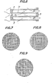
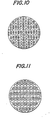
- the pattern of sealing the channels is not limited to the checker pattern shown in Figure 3 and the alternate row pattern shown in Figure 4; other sealing patterns include a spiral pattern (Figure 7), a concentric tetragonal pattern (Figure 8), a stepped pattern ( Figure 9) and a cross pattern (Figure 10).
- the shape of the channels may be other than tetragonal, for example another polygonal shape such as triangular or hexagonal, or circular or oval. Circular channels are shown in Figure 11.
- the ceramic honeycomb body has a wall thickness of 0.10-1.0 mm, preferably 0.15-0.80 mm, a channel number of 3.9-93/cm 2 (25-600/inch z ), preferably 7.8-46.5/cm2 (50-300/inch 2 ), and a porosity of 30-60%.
- the filter preferably has a diameter of 50-300 mm and a length of 50-400 mm and the shape of the filter may be other than a circular column, for example an oval column or a polygonal-column.
- the filter size in the radial direction may be optionally enarged by bonding several filters.
- FIG. 6 is an enlarged fragmentary view of a part of the honeycomb structural body shown in Figure 5.
- This filter is set so that the direction of the channels is parallel to the flow of dust-containing gas and the gas flow passes into the filter through an opening portion 2a of a gas inlet end face and passes through thin porous ceramic partition walls 1 a and 1 b having communicating pores, because the other end face of the respective channel is sealed with sealing material 3, and the gas flow transfers to the adjacent channels which open at the gas outlet side and is discharged.
- the thin porous partition walls having communicating pores function as a filter and the entrained fine particles in the gas are filtered.
- the filter Since the filter has a honeycomb structure the available area of the filter per unit volume is noticeably increased, and since the thickness of the partition walls is very thin the pressure drop is relatively low even when a high filtration rate is required, and the structure can be compact.
- the structure may be composed of a porous ceramic material having excellent heat resistance and thermal shock resistance, so that the filter can be used at high temperatures and is very stable to sudden temperature variation. Therefore, the filter clogged with fine particles can be exposed to a fairly high temperature, so that the fine particles can be removed by burning, whereby the filter function can be recovered. Accordingly, the filter is very effective for removing fine carbon dust from exhaust gases of Diesel engines and other internal combustion engines at high temperatures.
- the filter may be coated with a catalyst and the clogged fine particles burnt at a low temperature to recover the filter function.
- a honeycomb filter wherein both ends are sealed in checker pattern as shown in Figure 3 was prepared.
- the material for sealing the channels was the same as that forming the honeycomb structural body, and after moulding the honeycomb body the channels were sealed and then fired.
- the obtained cordierite honeycomb had a porosity of 43% and an average pore diameter of 10 ⁇ m.
- the pressure drop of this sample was measured by using air at room temperature, and the pressure drop was 50 mm H 2 0 (490 Pa) at a flow rate of 2 m 3 /min.
- the filter area was about 12,700 cm Z .
- the wall thickness of the ceramic filter was 3 mm, which is thin as production permits.
- the material forming the filter was cordierite, the porosity was 45%, the average pore diameter was 20 pm and the filter area was about 770 cm 2 .
- the pressure loss measured by using air at room temperature was 1,800 mm H 2 0 (17646 Pa) at a flow rate of 2 m 3 /min, i.e. the pressure drop was about 35 times as high as the previously described honeycomb filter, and the filter area was far smaller than the previously described honeycomb filter.
- a honeycomb filter wherein both ends are sealed as shown in Figure 4 was prepared.
- the material for sealing the channels was the same as that forming the honeycomb structural body, and after moulding and firing the honeycomb body the channels were sealed and again fired.
- the obtained mullite honeycomb had a porosity of 41 % and an average pore diameter of 14 ⁇ m.
- the pressure drop of the sampie was measured by using air at room temperature, and the pressure drop was 40 mm H 2 0 (392 Pa) at a flow rate of 2 m 3 /min.
- the filter area was about 11,000 cm 2 .
- a honeycomb filter was prepared by sealing channels of a honeycomb having a diameter of 120 mm, a tength of 150 mm, a thickness of the partition walls of the channels of 0.43 mm and a number of channels per square inch of about 100 (15. 5/cm 2 ), with the same material as that forming the honeycomb structural body in a checker pattern as shown in Figure 3.
- the pressure drop of the filter was found to be 80 mm H 2 0 (784 Pa) by using air at room temperature at a flow rate of 2 m 3 /min.
- the filter was not at all damaged and the fine carbon particles were burnt, and the pressure drop measured by using air at room temperature was 80 mm H 2 0 (784 Pa) at a flow rate of 2 m 3 /min whereby it was confirmed that the filter function has been recovered.
Landscapes
- Chemical & Material Sciences (AREA)
- Engineering & Computer Science (AREA)
- Chemical Kinetics & Catalysis (AREA)
- Ceramic Engineering (AREA)
- Inorganic Chemistry (AREA)
- Structural Engineering (AREA)
- Geology (AREA)
- Materials Engineering (AREA)
- Life Sciences & Earth Sciences (AREA)
- Organic Chemistry (AREA)
- Physics & Mathematics (AREA)
- Geometry (AREA)
- Combustion & Propulsion (AREA)
- Mechanical Engineering (AREA)
- General Engineering & Computer Science (AREA)
- Filtering Materials (AREA)
- Filtering Of Dispersed Particles In Gases (AREA)
Description
- The present invention relates to a ceramic filter for removing fine particles contained in gases, and more particularly to a ceramic honeycomb filter which has excellent heat resistance and thermal shock resistance, is small in size and has a very large filter area.
- Known filters include ones wherein various fillers, such as adsorbing material, steel wools, ceramic fibres, and porous porcelains, are arranged. However, in filters aiming at removing fine particles, unless filters having fine meshes are used, the removing efficiency cannot .be improved but on the contrary a disadvantageous increase of the pressure drop results when a high filtration rate is required.
- As means for enlarging the filter area in the prior sheet-formed, plate-formed or cylindrical filters, there are used relatively simple structures, such as corrugated structures and double cylindrical forms. However, a notable increase of the filter area per unit volume has not been attained. Therefore, in order to avoid a high pressure drop, the filter volume has been made larger and it has been very difficult to obtain a filter of smaller size.
- Various processes for producing ceramic honeycomb structural bodies are known and include, for example, a paper dipping process wherein an organic porous sheet is impregnated with a ceramic slurry and a honeycomb body is formed and the formed body is fired, a pipe binding process wherein a large number of pipes of given shape are bound, an extrusion process wherein a raw batch material is extruded through a die provided with a large number of given shaped slits, and a press process.
- The method for producing a ceramic honeycomb structural body will now be explained in more detail with respect to an extrusion process. To fine powder of a ceramic raw material, such as alumina, silica, mullite, silicon carbide, silicon nitride and/or cordierite, are added an organic binder and a plasticizer, the mixture is kneaded to prepare a composition consisting mainly of ceramic raw material, this composition is extruded through a die provided with a large number of slits, which forms a monolithic structure having channels of given shape in cross-section, for example polygonal such as triangular, tetragonal or hexagonal, circular or oval, and the shaped structure is dried and fired to obtain a porous ceramic honeycomb body.
- Honeycomb structural bodies have been recently used as catalyst supports for purifying exhaust gases of automobiles, and as heat exchangers for gas turbines. As mentioned above, a large number of parallel channels of given shape extending therethrough are uniformly distributed, so that the pressure drop of the gas flow is very small and the surface area per unit volume is large and the channels are constructed of thin walls, so that such a body can be easily heated up. However, in such ceramic honeycomb bodies, the large number of channels defined by the thin partition walls have been limited to the function of passages for flowing gas.
- The present invention provides a ceramic filter comprising a honeycomb structural body having parallel longitudinally extending channels defined by gas permeable porous ceramic walls, wherein the number of channels in the honeycomb body is 3.9-93/cm2 (25-600/inchj) and wherein the walls forming the channels are of a substantially constant thickness of 0.10 to 1.0 mm, and wherein one end face of some channels of the honeycomb body is sealed with a sealing material which is the same as the ceramic material forming the honeycomb body and the other end face of the remaining channels is also sealed with the same sealing material.
- I In a honeycomb filter body according to the invention, the thickness thereof can be far thinner than that of a conventional ceramic filter and the available area of the filter can be structural enlarged, and even if a filter material having a fine structure is used in order to remove fine particles, the pressure drop is not increased and a compact structure can be obtained.
- The invention will be further described, by way of example only, with reference to the accompanying drawings wherein:
- Figure 1 is an end view of a previously known honeycomb structural body;
- Figure 2 is a partially cut away side view of the honeycomb structural body shown in Figure 1;
- Figure 3 is an end view of one embodiment of a honeycomb structural body comprising a filter according to the present invention;
- Figure 4 is an end view of another embodiment of a honeycomb structural body comprising filter according to the present invention;
- Figure 5 is a partially cut away side view of the honeycomb structural body shown in Figure 4;
- Figure 6 is an enlarged fragmentary view of a part of the honeycomb structural body of Figure 5; and
- Figures 7-11 are end views of other embodiments of honeycomb structural bodies comprising filters according to the present invention.
- Figures 1 and 2 show a conventional honeycomb structural body in which the cross- sectional shape of a large number of
parallel channels 2 extending therethrough is tetragonal and each channel is defined by very thin partition walls 1. - Figure 3 shows one embodiment of a honeycomb structural body wherein one end surface of the channels of the honeycomb body is sealed in a checker pattern, and Figures 4 and 5 show an embodiment of a honeycomb structural body wherein one end surface of the channels is sealed in alternate rows. Thus, the thin porous partition walls forming the channels are used as a filter by sealing one end of the channels in the honeycomb structural body. When sealing the channels, a suitable mask is used and the sealing material is the same ceramic material as that forming the ceramic honeycomb body, in order to achieve good heat resistance and thermal shock resistance. The pattern of sealing the channels is not limited to the checker pattern shown in Figure 3 and the alternate row pattern shown in Figure 4; other sealing patterns include a spiral pattern (Figure 7), a concentric tetragonal pattern (Figure 8), a stepped pattern (Figure 9) and a cross pattern (Figure 10). The shape of the channels may be other than tetragonal, for example another polygonal shape such as triangular or hexagonal, or circular or oval. Circular channels are shown in Figure 11.
- The ceramic honeycomb body has a wall thickness of 0.10-1.0 mm, preferably 0.15-0.80 mm, a channel number of 3.9-93/cm2 (25-600/inchz), preferably 7.8-46.5/cm2 (50-300/inch2), and a porosity of 30-60%. The filter preferably has a diameter of 50-300 mm and a length of 50-400 mm and the shape of the filter may be other than a circular column, for example an oval column or a polygonal-column. The filter size in the radial direction may be optionally enarged by bonding several filters.
- A further explanation will now be made with respect to the effect of the filter according to the present invention. Figure 6 is an enlarged fragmentary view of a part of the honeycomb structural body shown in Figure 5. This filter is set so that the direction of the channels is parallel to the flow of dust-containing gas and the gas flow passes into the filter through an opening portion 2a of a gas inlet end face and passes through thin porous ceramic partition walls 1 a and 1 b having communicating pores, because the other end face of the respective channel is sealed with sealing
material 3, and the gas flow transfers to the adjacent channels which open at the gas outlet side and is discharged. Thus, the thin porous partition walls having communicating pores function as a filter and the entrained fine particles in the gas are filtered. - Since the filter has a honeycomb structure the available area of the filter per unit volume is noticeably increased, and since the thickness of the partition walls is very thin the pressure drop is relatively low even when a high filtration rate is required, and the structure can be compact. By controlling the pore distribution and porosity of the porous material, fine particles of various sizes can be filtered. Furthermore, the structure may be composed of a porous ceramic material having excellent heat resistance and thermal shock resistance, so that the filter can be used at high temperatures and is very stable to sudden temperature variation. Therefore, the filter clogged with fine particles can be exposed to a fairly high temperature, so that the fine particles can be removed by burning, whereby the filter function can be recovered. Accordingly, the filter is very effective for removing fine carbon dust from exhaust gases of Diesel engines and other internal combustion engines at high temperatures.
- If possible, the filter may be coated with a catalyst and the clogged fine particles burnt at a low temperature to recover the filter function.
- The invention will now be further described with reference to the following illustrative Examples.
- By using a cordierite honeycomb having a diameter of 120 mm, a length of 120 mm, a thicknes of the partition walls of the channels of 0.30 mm and a number of channels per square inch of about 200 (31.0/cm2), a honeycomb filter wherein both ends are sealed in checker pattern as shown in Figure 3 was prepared. The material for sealing the channels was the same as that forming the honeycomb structural body, and after moulding the honeycomb body the channels were sealed and then fired.
- The obtained cordierite honeycomb had a porosity of 43% and an average pore diameter of 10 µm. The pressure drop of this sample was measured by using air at room temperature, and the pressure drop was 50 mm H20 (490 Pa) at a flow rate of 2 m3/min. The filter area was about 12,700 cm Z .
- For comparison, a cylindrical ceramic filter having the same diameter and length as the above described honeycomb structural body, one end of the cylinder being sealed, was prepared and the pressure drop of this filter was measured. The wall thickness of the ceramic filter was 3 mm, which is thin as production permits. The material forming the filter was cordierite, the porosity was 45%, the average pore diameter was 20 pm and the filter area was about 770 cm2. The pressure loss measured by using air at room temperature was 1,800 mm H20 (17646 Pa) at a flow rate of 2 m3/min, i.e. the pressure drop was about 35 times as high as the previously described honeycomb filter, and the filter area was far smaller than the previously described honeycomb filter.
- By using a mullite honeycomb having a diameter of 140 mm, a length of 150 mm, a thickness of the partition walls of the channels of 0.30 mm and a number of channels per square inch of about 200 (31.0/cm2), a honeycomb filter wherein both ends are sealed as shown in Figure 4 was prepared. The material for sealing the channels was the same as that forming the honeycomb structural body, and after moulding and firing the honeycomb body the channels were sealed and again fired.
- The obtained mullite honeycomb had a porosity of 41 % and an average pore diameter of 14 µm. The pressure drop of the sampie was measured by using air at room temperature, and the pressure drop was 40 mm H20 (392 Pa) at a flow rate of 2 m3/min. The filter area was about 11,000 cm 2.
- A honeycomb filter was prepared by sealing channels of a honeycomb having a diameter of 120 mm, a tength of 150 mm, a thickness of the partition walls of the channels of 0.43 mm and a number of channels per square inch of about 100 (15. 5/cm2), with the same material as that forming the honeycomb structural body in a checker pattern as shown in Figure 3. The pressure drop of the filter was found to be 80 mm H20 (784 Pa) by using air at room temperature at a flow rate of 2 m3/min.
- When exhaust gas of a Diesel engine was passed through this filter to collect 7 g of fine carbon particles, the pressure drop measured by using air at room temperature was 800 mm H20 (7840 Pa) at a flow rate of 2 m3/min. It has been generally known that fine carbon particles in the exhaust gas of a Diesel engine are burnt at a temperature of 550-650°C, but for the purpose of determining the heat resistance of the filter wherein carbon has collected the filter was put in an electric furnace and treated at 1,200° C for 30 minutes.
- As a result, the filter was not at all damaged and the fine carbon particles were burnt, and the pressure drop measured by using air at room temperature was 80 mm H20 (784 Pa) at a flow rate of 2 m3/min whereby it was confirmed that the filter function has been recovered.
Claims (4)
Applications Claiming Priority (2)
| Application Number | Priority Date | Filing Date | Title |
|---|---|---|---|
| JP33202/80 | 1980-03-15 | ||
| JP3320280A JPS56129020A (en) | 1980-03-15 | 1980-03-15 | Ceramic filter |
Publications (2)
| Publication Number | Publication Date |
|---|---|
| EP0036321A1 EP0036321A1 (en) | 1981-09-23 |
| EP0036321B1 true EP0036321B1 (en) | 1984-06-27 |
Family
ID=12379878
Family Applications (1)
| Application Number | Title | Priority Date | Filing Date |
|---|---|---|---|
| EP81301091A Expired EP0036321B1 (en) | 1980-03-15 | 1981-03-16 | Ceramic filter |
Country Status (3)
| Country | Link |
|---|---|
| EP (1) | EP0036321B1 (en) |
| JP (1) | JPS56129020A (en) |
| DE (1) | DE3164378D1 (en) |
Cited By (1)
| Publication number | Priority date | Publication date | Assignee | Title |
|---|---|---|---|---|
| US8080082B2 (en) | 1999-09-29 | 2011-12-20 | Ibiden Co., Ltd. | Honeycomb filter and method for producing the honeycomb filter |
Families Citing this family (25)
| Publication number | Priority date | Publication date | Assignee | Title |
|---|---|---|---|---|
| DE3173763D1 (en) | 1980-07-03 | 1986-03-27 | Corning Glass Works | Particulate filter and material for producing the same |
| DE3101026A1 (en) * | 1981-01-15 | 1982-08-26 | Engelhard Kali-Chemie Autocat Gmbh, 3000 Hannover | BIFUNCTIONAL FILTER FOR TREATING EXHAUST GAS |
| JPS5870814A (en) * | 1981-10-20 | 1983-04-27 | Nippon Soken Inc | Structure for purifying exhaust gas |
| JPS57187013A (en) * | 1981-05-11 | 1982-11-17 | Toyota Motor Corp | Waste gas filter |
| EP0070671B1 (en) * | 1981-07-15 | 1986-12-03 | Corning Glass Works | Selective charging honeycomb structures |
| US5021204A (en) * | 1981-07-15 | 1991-06-04 | Corning Incorporated | Method for selectively charging honeycomb structures |
| US4557773A (en) * | 1981-07-15 | 1985-12-10 | Corning Glass Works | Method for selectively manifolding honeycomb structures |
| US4455180A (en) * | 1981-08-24 | 1984-06-19 | Corning Glass Works | Method of fabricating a sintered and selectively plugged honeycomb structure |
| US4417908A (en) * | 1982-02-22 | 1983-11-29 | Corning Glass Works | Honeycomb filter and method of making it |
| JPS58197848A (en) * | 1982-05-14 | 1983-11-17 | Oki Electric Ind Co Ltd | Manufacture of multi-layer wiring structure |
| JPS58183206U (en) * | 1982-05-31 | 1983-12-06 | いすゞ自動車株式会社 | Ceramic filter for tank cars transporting powder and granular materials |
| JPS59184285A (en) * | 1983-04-04 | 1984-10-19 | Nippon Steel Chem Co Ltd | Dust collector for coke oven |
| US4830749A (en) * | 1986-07-15 | 1989-05-16 | Ngk Insulators, Ltd. | Liquid waste filtering apparatus |
| JPH01159408A (en) * | 1987-09-25 | 1989-06-22 | Asahi Glass Co Ltd | Exhaust gas processor for diesel engine and method thereof |
| US5062911A (en) * | 1989-12-21 | 1991-11-05 | Corning Incorporated | Preparation of ceramic honeycomb structure having selectively sealed channels |
| JP3147372B2 (en) * | 1990-10-10 | 2001-03-19 | 株式会社日本自動車部品総合研究所 | Exhaust gas particulate collection filter |
| US5253476A (en) * | 1992-02-21 | 1993-10-19 | Northeastern University | Pulsed, reverse-flow, regenerated diesel trap capturing soot, ash and PAH's |
| US5426936A (en) * | 1992-02-21 | 1995-06-27 | Northeastern University | Diesel engine exhaust gas recirculation system for NOx control incorporating a compressed air regenerative particulate control system |
| DE69629979T2 (en) * | 1995-06-02 | 2004-07-29 | Corning Inc. | Device for removing contaminants from fluid streams |
| JP3983117B2 (en) | 2001-07-31 | 2007-09-26 | 日本碍子株式会社 | Honeycomb structure and manufacturing method thereof |
| WO2003074848A1 (en) † | 2002-03-04 | 2003-09-12 | Ibiden Co., Ltd. | Honeycomb filter for exhaust gas decontamination and exhaust gas decontamination apparatus |
| JP4773043B2 (en) | 2003-03-28 | 2011-09-14 | 日本碍子株式会社 | Ceramic filter structure |
| JP4640987B2 (en) | 2003-08-12 | 2011-03-02 | 日本碍子株式会社 | Ceramic filter |
| JP2005169308A (en) | 2003-12-12 | 2005-06-30 | Ngk Insulators Ltd | Honeycomb filter and its production method |
| JP2009154124A (en) | 2007-12-27 | 2009-07-16 | Ngk Insulators Ltd | Partially unsealed dpf |
Citations (6)
| Publication number | Priority date | Publication date | Assignee | Title |
|---|---|---|---|---|
| US994282A (en) * | 1910-05-07 | 1911-06-06 | Just Process Company | Apparatus for separating solid particles from gaseous fluids. |
| FR1515158A (en) * | 1967-01-17 | 1968-03-01 | Sfec | Improvements to catalyst supports |
| US3458977A (en) * | 1964-05-19 | 1969-08-05 | Wix Corp | Filters |
| DE2248359A1 (en) * | 1971-09-30 | 1973-04-05 | Minnesota Mining & Mfg | FILTER |
| US4178145A (en) * | 1976-04-26 | 1979-12-11 | Kyoto Ceramic Co., Ltd. | Extrusion die for ceramic honeycomb structures |
| DE2900705A1 (en) * | 1979-01-10 | 1980-07-24 | Ind Wert Beteiligungsgesellsch | Hot gas filters - made from expanded calcium aluminium silicate and sodium silicate binder |
Family Cites Families (3)
| Publication number | Priority date | Publication date | Assignee | Title |
|---|---|---|---|---|
| DE1097344B (en) * | 1958-09-08 | 1961-01-12 | Corning Glass Works | Process for the production of ceramic objects with honeycomb-like cross-sections |
| JPS4938266A (en) * | 1972-08-16 | 1974-04-09 | ||
| JPS55114324A (en) * | 1979-02-27 | 1980-09-03 | Noritake Co Ltd | Filter unit |
-
1980
- 1980-03-15 JP JP3320280A patent/JPS56129020A/en active Pending
-
1981
- 1981-03-16 EP EP81301091A patent/EP0036321B1/en not_active Expired
- 1981-03-16 DE DE8181301091T patent/DE3164378D1/en not_active Expired
Patent Citations (6)
| Publication number | Priority date | Publication date | Assignee | Title |
|---|---|---|---|---|
| US994282A (en) * | 1910-05-07 | 1911-06-06 | Just Process Company | Apparatus for separating solid particles from gaseous fluids. |
| US3458977A (en) * | 1964-05-19 | 1969-08-05 | Wix Corp | Filters |
| FR1515158A (en) * | 1967-01-17 | 1968-03-01 | Sfec | Improvements to catalyst supports |
| DE2248359A1 (en) * | 1971-09-30 | 1973-04-05 | Minnesota Mining & Mfg | FILTER |
| US4178145A (en) * | 1976-04-26 | 1979-12-11 | Kyoto Ceramic Co., Ltd. | Extrusion die for ceramic honeycomb structures |
| DE2900705A1 (en) * | 1979-01-10 | 1980-07-24 | Ind Wert Beteiligungsgesellsch | Hot gas filters - made from expanded calcium aluminium silicate and sodium silicate binder |
Cited By (2)
| Publication number | Priority date | Publication date | Assignee | Title |
|---|---|---|---|---|
| US8080082B2 (en) | 1999-09-29 | 2011-12-20 | Ibiden Co., Ltd. | Honeycomb filter and method for producing the honeycomb filter |
| US8083826B2 (en) | 1999-09-29 | 2011-12-27 | Ibiden Co., Ltd. | Honeycomb filter and method for producing the honeycomb filter |
Also Published As
| Publication number | Publication date |
|---|---|
| DE3164378D1 (en) | 1984-08-02 |
| EP0036321A1 (en) | 1981-09-23 |
| JPS56129020A (en) | 1981-10-08 |
Similar Documents
| Publication | Publication Date | Title |
|---|---|---|
| EP0036321B1 (en) | Ceramic filter | |
| US4364760A (en) | Ceramic honeycomb filter | |
| EP0042300B1 (en) | Ceramic honeycomb filters and the production thereof | |
| US4293357A (en) | Method for producing ceramic honeycomb filters | |
| EP1413345B1 (en) | Honeycomb structural body and method of manufacturing the structural body | |
| EP0042301B1 (en) | Ceramic honeycomb filters and the production thereof | |
| JP4699451B2 (en) | Diesel engine exhaust filter | |
| JP4367683B2 (en) | Honeycomb filter | |
| KR100602867B1 (en) | Honeycomb filter | |
| EP2368619B1 (en) | Ceramic honeycomb structures | |
| EP1484483B1 (en) | Honeycomb filter | |
| CA1314496C (en) | Ceramic honeycomb filter for purifying exhaust gases | |
| EP1382445B1 (en) | A method of manufacturing a filter for purifying exhaust gas | |
| JP2003010616A (en) | Honeycomb structure body | |
| EP1251247A1 (en) | Exhaust gas purifying filter | |
| EP2698191B1 (en) | Plugged honeycomb structure | |
| EP2698190B1 (en) | Plugged Honeycomb Structure | |
| JP4426381B2 (en) | Honeycomb structure and manufacturing method thereof | |
| JPH0647620U (en) | Exhaust gas purification device | |
| US7468156B2 (en) | Method for manufacturing porous ceramic structure | |
| JP4146048B2 (en) | Honeycomb filter, honeycomb filter assembly, | |
| JPS6147136B2 (en) | ||
| JPH06241018A (en) | Exhaust gas purifier | |
| KR19980051300A (en) | Manufacturing method of ceramic filter with different pore characteristics in thickness direction |
Legal Events
| Date | Code | Title | Description |
|---|---|---|---|
| PUAI | Public reference made under article 153(3) epc to a published international application that has entered the european phase |
Free format text: ORIGINAL CODE: 0009012 |
|
| ITCL | It: translation for ep claims filed |
Representative=s name: AVV. GIOVANNI LECCCE |
|
| AK | Designated contracting states |
Designated state(s): BE DE FR GB IT SE |
|
| DET | De: translation of patent claims | ||
| 17P | Request for examination filed |
Effective date: 19820112 |
|
| ITF | It: translation for a ep patent filed |
Owner name: BARZANO' E ZANARDO MILANO S.P.A. |
|
| GRAA | (expected) grant |
Free format text: ORIGINAL CODE: 0009210 |
|
| AK | Designated contracting states |
Designated state(s): BE DE FR GB IT SE |
|
| REF | Corresponds to: |
Ref document number: 3164378 Country of ref document: DE Date of ref document: 19840802 |
|
| ET | Fr: translation filed | ||
| PLBE | No opposition filed within time limit |
Free format text: ORIGINAL CODE: 0009261 |
|
| STAA | Information on the status of an ep patent application or granted ep patent |
Free format text: STATUS: NO OPPOSITION FILED WITHIN TIME LIMIT |
|
| 26N | No opposition filed | ||
| ITTA | It: last paid annual fee | ||
| EAL | Se: european patent in force in sweden |
Ref document number: 81301091.5 |
|
| PGFP | Annual fee paid to national office [announced via postgrant information from national office to epo] |
Ref country code: GB Payment date: 20000306 Year of fee payment: 20 |
|
| PGFP | Annual fee paid to national office [announced via postgrant information from national office to epo] |
Ref country code: FR Payment date: 20000320 Year of fee payment: 20 |
|
| PGFP | Annual fee paid to national office [announced via postgrant information from national office to epo] |
Ref country code: SE Payment date: 20000322 Year of fee payment: 20 Ref country code: DE Payment date: 20000322 Year of fee payment: 20 |
|
| PGFP | Annual fee paid to national office [announced via postgrant information from national office to epo] |
Ref country code: BE Payment date: 20000329 Year of fee payment: 20 |
|
| BE20 | Be: patent expired |
Free format text: 20010316 *NGK INSULATORS LTD |
|
| PG25 | Lapsed in a contracting state [announced via postgrant information from national office to epo] |
Ref country code: GB Free format text: LAPSE BECAUSE OF EXPIRATION OF PROTECTION Effective date: 20010315 |
|
| PG25 | Lapsed in a contracting state [announced via postgrant information from national office to epo] |
Ref country code: SE Free format text: THE PATENT HAS BEEN ANNULLED BY A DECISION OF A NATIONAL AUTHORITY Effective date: 20010330 |
|
| REG | Reference to a national code |
Ref country code: GB Ref legal event code: PE20 Effective date: 20010315 |
|
| EUG | Se: european patent has lapsed |
Ref document number: 81301091.5 |