EP0023953A1 - Sealing and bearing for the shaft of a swinging flap - Google Patents
Sealing and bearing for the shaft of a swinging flap Download PDFInfo
- Publication number
- EP0023953A1 EP0023953A1 EP80103179A EP80103179A EP0023953A1 EP 0023953 A1 EP0023953 A1 EP 0023953A1 EP 80103179 A EP80103179 A EP 80103179A EP 80103179 A EP80103179 A EP 80103179A EP 0023953 A1 EP0023953 A1 EP 0023953A1
- Authority
- EP
- European Patent Office
- Prior art keywords
- shaft
- ring
- flap
- bearing
- seal
- Prior art date
- Legal status (The legal status is an assumption and is not a legal conclusion. Google has not performed a legal analysis and makes no representation as to the accuracy of the status listed.)
- Withdrawn
Links
Images
Classifications
-
- F—MECHANICAL ENGINEERING; LIGHTING; HEATING; WEAPONS; BLASTING
- F16—ENGINEERING ELEMENTS AND UNITS; GENERAL MEASURES FOR PRODUCING AND MAINTAINING EFFECTIVE FUNCTIONING OF MACHINES OR INSTALLATIONS; THERMAL INSULATION IN GENERAL
- F16J—PISTONS; CYLINDERS; SEALINGS
- F16J15/00—Sealings
- F16J15/16—Sealings between relatively-moving surfaces
- F16J15/34—Sealings between relatively-moving surfaces with slip-ring pressed against a more or less radial face on one member
- F16J15/3464—Mounting of the seal
-
- F—MECHANICAL ENGINEERING; LIGHTING; HEATING; WEAPONS; BLASTING
- F16—ENGINEERING ELEMENTS AND UNITS; GENERAL MEASURES FOR PRODUCING AND MAINTAINING EFFECTIVE FUNCTIONING OF MACHINES OR INSTALLATIONS; THERMAL INSULATION IN GENERAL
- F16K—VALVES; TAPS; COCKS; ACTUATING-FLOATS; DEVICES FOR VENTING OR AERATING
- F16K1/00—Lift valves or globe valves, i.e. cut-off apparatus with closure members having at least a component of their opening and closing motion perpendicular to the closing faces
- F16K1/16—Lift valves or globe valves, i.e. cut-off apparatus with closure members having at least a component of their opening and closing motion perpendicular to the closing faces with pivoted closure-members
- F16K1/18—Lift valves or globe valves, i.e. cut-off apparatus with closure members having at least a component of their opening and closing motion perpendicular to the closing faces with pivoted closure-members with pivoted discs or flaps
- F16K1/22—Lift valves or globe valves, i.e. cut-off apparatus with closure members having at least a component of their opening and closing motion perpendicular to the closing faces with pivoted closure-members with pivoted discs or flaps with axis of rotation crossing the valve member, e.g. butterfly valves
- F16K1/226—Shaping or arrangements of the sealing
- F16K1/2268—Sealing means for the axis of rotation
Definitions
- the invention relates to a pendulum flap, the shaft of which is sealed by means of a seal and is guided through a wall of the flap housing to the outside and is mounted outside the housing interior, a compression spring being arranged on the shaft between the bearing and the seal.
- Swing flaps of various designs are used in practice for the introduction and discharge of bulk goods of all kinds in silos, heat treatment devices, coolers, air classifiers and the like. Since there is usually a different pressure in such facilities than outside, they are intended to prevent false air from flowing into the room at a lower pressure when bulk material is conveyed by such a swing flap. The fulfillment of such a requirement, however, presupposes that the seal for the valve shaft, which is located between the bearing and the valve housing, functions reliably.
- the seal arranged between the flap housing and the bearing can only maintain the desired seal at relatively low temperatures and relatively light operating conditions; in the case of more severe applications and especially at higher operating temperatures, the intended seal fails in most cases.
- the escaping, sometimes extremely abrasive material to be conveyed increases the leaks even more and inevitably leads to one Destruction of the shaft bearings.
- a tight closing of the butterfly valve itself is no longer possible, with the result that the desired function of the swing valve is no longer provided and that the corresponding valve parts are worn out to such an extent within a relatively short time that further use of the swing valve is impossible.
- the invention is therefore based on the object, while avoiding the shortcomings of the known design, to create a pendulum flap of the type mentioned, which is particularly reliable because of its seal, which always works reliably in all operating conditions (even at higher operating temperatures).
- the seal contains a slip ring provided with a flat ground sealing surface and a spherical bearing surface and a pressure ring which receives the slip ring in a corresponding spherical recess.
- the pressure ring and the intended slip ring by dome-shaped bearing surfaces engaged with each other can also even at the occurrence of misalignments of the flap shaft or with a delay of the valve body (by superheating) always at the same everywhere even and gap-free concerns plangeschliffencn sealing surface guaranteed of the slip ring on its counter sealing surface will. In this way, a reliable seal between the corresponding housing wall and the valve shaft can be maintained even under extreme operating conditions.
- a grinding cup surrounding the shaft is installed in a fixed and sealed manner and has a ring-shaped, counter-sealing surface which is in sliding engagement with the flat-ground sealing surface of the slip ring and is also flat-ground.
- a recess is provided on the side of the pressure ring axially opposite the dome-shaped recess for receiving a static sealing element between the shaft and the pressure ring. This creates a particularly reliable seal between the annular gap between the shaft and the pressure ring.
- a fabric ring preferably an asbestos-molykote fabric ring
- this sealing effect can also be maintained unchanged if a possible axial displacement of the shaft occurs.
- the fabric ring used as a static sealing element has the outer shape of a truncated cone in the axial direction and the pressure ring recess has a shape corresponding thereto, the compression spring acting on the pressure ring via the fabric ring.
- the necessary contact pressure of the slip ring (via the pressure ring) is then generated on the counter-sealing surface and, on the other hand, a constant sufficient prestress is exerted on the fabric ring, so that both the static seal and the dynamic seal are reliably guaranteed via the compression spring.
- the sealing parts of the cup wheel build up axially in the direction of the associated bearing provided on the side of the corresponding housing wall.
- the seal is arranged to a substantial extent outside the housing, so that these parts are not only removed from the particularly dust-laden air streams present in the interior of the housing, but also from the hotter operating range.
- the embodiment according to the invention can be assembled particularly easily if the bearing is screwed together with the flange of the cup to the wall of the valve housing.
- a radial spherical plain bearing is provided as a bearing for the flap shaft. It has been shown that such a type of bearing favors the effectiveness of the seal due to the unfavorable mechanical loads and the possible high operating temperatures. Such a bearing can work largely maintenance-free even under extreme conditions and also automatically compensate for any existing or emerging misalignments of the shaft or housing distortions (due to overheating).
- a pendulum flap according to the invention can be either a simple pendulum flap (i.e. with only a single sealing flap inside the housing) or a double pendulum flap, in which case then alternating pendulum movements of the two one above the other A flap-like inlet or outlet effect is achieved in the sealing flaps arranged in the housing.
- a shaft which is usually guided in a sealed manner through opposite housing walls and is then mounted outside the actual housing.
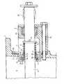
- the drawing shows only a partial sectional view through a pendulum flap designed according to the invention, specifically in the area of a housing wall penetrated by the flap shaft.
- the pendulum flap contains a flap housing 1, a flap shaft 2, which is guided to the outside through the flap housing wall 3, a seal 4 and a bearing 6 lying outside the housing interior 5; the shaft end 2a projecting axially outward from the bearing 6 can be connected in the usual way to a drive device (not illustrated in any more detail).
- An essential part of this invention is the design and arrangement of the seal 4, which seals the housing interior 5 at the passage point of the shaft 2 through the housing wall 3.
- This seal 4 initially contains as an essential component a slip ring 7, which surrounds the shaft 2 at a distance and is made of a suitable, temperature-resistant material (e.g. temperature-resistant steel) plane-ground sealing surface 7a, while on its axially opposite side it has a spherical bearing surface 7b.
- a suitable, temperature-resistant material e.g. temperature-resistant steel
- the slip ring 7 stands in Sealing sliding engagement with a likewise flat-ground, annular counter-sealing surface 8a of a cup wheel 8 which surrounds the shaft 2 at a distance and which is installed in a corresponding opening 3a in the housing wall 3.
- the spherical bearing surface 7b of the slip ring 7, is in engagement with a suitably designed spherical recess 9a of a pressure ring 9 surrounding the shaft 2 with little play.
- the pressure ring 9 is under the action of a compression spring 10, which is preferably designed as a temperature-resistant, cylindrical helical spring, arranged between two rings 11, 12 surrounding the shaft 2 and secured in its pretension by a cross pin 13 penetrating the shaft 2.
- a compression spring 10 which is preferably designed as a temperature-resistant, cylindrical helical spring, arranged between two rings 11, 12 surrounding the shaft 2 and secured in its pretension by a cross pin 13 penetrating the shaft 2.
- the compression spring 10 does not act directly on the pressure ring 9, but with the interposition of a static sealing element 14, which is accommodated in a recess 9b of this pressure ring on the side of the pressure ring axially opposite the spherical recess 9a and a possibly existing annular gap between shaft 2 and pressure ring 9 seals.
- This static sealing element is preferably formed by an asbestos-molykote fabric ring 14 which - as the drawing clearly shows - has the outer shape of a truncated cone in the axial direction, while the pressure ring recess 9b accordingly has a shape corresponding thereto.
- the static sealing fabric ring 14 is therefore always sufficient the preload pressed into the compression ring recess 9b; At the same time, the necessary pressure is then exerted on the pressure ring 9 itself, which in turn transmits this pressure to the slip ring 7, so that this slip ring 7 with its plane-ground sealing surface 7a always lies sufficiently firmly against the counter-sealing surface 8a of the cup wheel 8.
- the bearing 6, which is arranged further outside the housing interior 5 with respect to the seal, can be screwed to the housing wall 3 by means of screws 15 through its housing 6a together with the outer flange 8b of the cup wheel 8.
- the particularly dust and temperature protected bearing 6 in this outer arrangement is preferably designed as a radial joint bearing, so that it can compensate for any misalignment particularly well.
- the latter is particularly advantageous also in connection with the seal 4 according to the invention, in which a possible relative displacement of the slip ring 7 and pressure ring 9 due to the spherical bearing surfaces 7b and 9a balanced between shaft 3 and housing 1 and thus always a reliable seal between slip ring 7 and cup 8 (on their sealing surfaces 7a and 8a) is maintained.
Landscapes
- Engineering & Computer Science (AREA)
- General Engineering & Computer Science (AREA)
- Mechanical Engineering (AREA)
- Sealing Devices (AREA)
- Sealing Of Bearings (AREA)
Abstract
Description
Die Erfindung betrifft eine Pendelklappe, deren Welle mittels einer Dichtung abgedichtet durch eine Wand des Klappengehäuses nach außen geführt und außerhalb des Gehäuse-Innenraumes gelagert ist, wobei auf der Welle zwischen dem Lager und der Dichtung eine Druckfeder angeordnet ist.The invention relates to a pendulum flap, the shaft of which is sealed by means of a seal and is guided through a wall of the flap housing to the outside and is mounted outside the housing interior, a compression spring being arranged on the shaft between the bearing and the seal.
Pendelklappen verschiedener Ausführungen werden in der Praxis zum Ein- und Austragen von Schüttgütern aller Art bei Silos, Wärmebehandlungseinrichtungen, Kühlern, Windsichtern und dergleichen verwendet. Da in solchen Einrichtungen meist ein anderer Druck als außerhalb herrscht, sollen sie verhindern, daß Falschluft in den Raum mit niedrigerem Druck einströmen kann, wenn Schüttgut durch eine solche Pendelklappe gefördert wird. Die Erfüllung einer solchen Forderung setzt jedoch voraus, daß die zwischen dem Lager und dem Klappengehäuse befindliche Dichtung für die Klappenwelle zuverlässig funktioniert.Swing flaps of various designs are used in practice for the introduction and discharge of bulk goods of all kinds in silos, heat treatment devices, coolers, air classifiers and the like. Since there is usually a different pressure in such facilities than outside, they are intended to prevent false air from flowing into the room at a lower pressure when bulk material is conveyed by such a swing flap. The fulfillment of such a requirement, however, presupposes that the seal for the valve shaft, which is located between the bearing and the valve housing, functions reliably.
Bei einer aus der Praxis bekannten Pendelklappen-Ausführung der eingangs genannten Art kann die zwischen Klappengehäuse und Lager angeordnete Dichtung die gewünschte Abdichtung nur bei verhältnismäßig niedrigen Temperaturen und relativ leichten Betriebsbedingungen aufrecht erhalten; bei schwereren Einsatzfällen und insbesondere bei höheren Betriebstemperaturen fällt die vorgesehene Dichtung in den meisten Fällen aus. Das dabei austretende, mitunter stark schleißende Fördergut erhöht die Undichtigkeiten noch mehr und führt zwangsläufig zu einer Zerstörung der Wellenlagerung. Hierdurch ist dann ein dichtes Abschließen der Absperrklappe selbst überhaupt nicht mehr möglich, mit der Folge, daß die gewünschte Funktion der Pendelklappe nicht mehr gegeben ist und daß innerhalb verhältnismäßig kurzer Zeit die entsprechenden Klappenteile so weit verschlissen werden, daß eine Weiterverwendung der Pendelklappe unmöglich wird.In a swing flap design of the type mentioned at the outset, the seal arranged between the flap housing and the bearing can only maintain the desired seal at relatively low temperatures and relatively light operating conditions; in the case of more severe applications and especially at higher operating temperatures, the intended seal fails in most cases. The escaping, sometimes extremely abrasive material to be conveyed increases the leaks even more and inevitably leads to one Destruction of the shaft bearings. As a result, a tight closing of the butterfly valve itself is no longer possible, with the result that the desired function of the swing valve is no longer provided and that the corresponding valve parts are worn out to such an extent within a relatively short time that further use of the swing valve is impossible.
Der Erfindung liegt daher die Aufgabe zugrunde, unter Vermeidung der aufgezeigten Mängel der bekannten Ausführung eine Pendelklappe der eingangs genannten Art zu schaffen, die sich insbesondere aufgrund ihrer bei allen Betriebsbedingungen (auch bei höheren Betriebstemperaturen) stets zuverlässig arbeitende Dichtung auszeichnet.The invention is therefore based on the object, while avoiding the shortcomings of the known design, to create a pendulum flap of the type mentioned, which is particularly reliable because of its seal, which always works reliably in all operating conditions (even at higher operating temperatures).
Diese Aufgabe wird erfindungsgemäß dadurch qelöst, daß die Dichtung einen mit einer plangeschliffenen Dichtungsfläche und einer kalottenförmigen Lagerfläche versehenen Schleifring sowie einen den Schleifring in einer entsprechenden kalottenförmigen Ausnehmung aufnehmenden Druckring enthält.This object is achieved according to the invention in that the seal contains a slip ring provided with a flat ground sealing surface and a spherical bearing surface and a pressure ring which receives the slip ring in a corresponding spherical recess.
Da bei dieser erfindungsgemäßen Ausführungsform der Druckring und der vorgesehene Schleifring durch kalottenförmige Lagerflächen miteinander in Eingriff stehen, kann auch selbst bei dem Auftreten von Fluchtfehlern der Klappenwelle oder bei einem Verzug des Klappengehäuses (durch Uberhitzung) stets ein überall gleichmäßiges und spaltfreies Anliegen der plangeschliffencn Dichtungsfläche des Schleifringes an seiner Gegendichtungsfläche gewährleistet werden. Auf diese Weise kann auch selbst bei extremen Betriebsbedingungen eine zuverlässige Abdichtung zwischen der entsprechenden Gehäusewand und der Klappenwelle aufrecht erhalten werden. D a are in this embodiment of the invention, the pressure ring and the intended slip ring by dome-shaped bearing surfaces engaged with each other, can also even at the occurrence of misalignments of the flap shaft or with a delay of the valve body (by superheating) always at the same everywhere even and gap-free concerns plangeschliffencn sealing surface guaranteed of the slip ring on its counter sealing surface will. In this way, a reliable seal between the corresponding housing wall and the valve shaft can be maintained even under extreme operating conditions.
Gemäß einer vorteilhaften Ausgestaltung der Erfindung ist in der die Dichtung enthaltenden Wand des Klappengehäuses ein die Welle umgebender Schleiftopf fest und abgedichtet eingebaut, der eine mit der plangeschliffenen Dichtungsfläche des Schleifringes in Gleiteingriff stehende, ebenfalls plangeschliffene, ringförmige Gegendichtungsfläche aufweist. Durch eine entsprechende Anordnung dieses Schleiftopfes in der Gehäusewand können von vornherein bereits alle groben Stäube und Verunreinigungen von den Dichtungsflächen, ferngehalten werden.According to an advantageous embodiment of the invention, in the wall of the flap housing containing the seal, a grinding cup surrounding the shaft is installed in a fixed and sealed manner and has a ring-shaped, counter-sealing surface which is in sliding engagement with the flat-ground sealing surface of the slip ring and is also flat-ground. By arranging this cup wheel in the housing wall, all coarse dusts and contaminants can be kept away from the sealing surfaces from the outset.
Es ist dabei ferner vorteilhaft, wenn auf der der kalottenförmigen Ausnehmung axial entgegengesetzten Seite des Druckringes eine Ausdrehung zur Aufnahme eines statischen Dichtungselemcnts zwischen Welle und Druckring vorgesehen ist. Hierdurch wird eine besonders zuverlässige Abdichtung des zwischen Welle und Druckring vorhandenen Ringspaltes geschaffen.It is also advantageous if a recess is provided on the side of the pressure ring axially opposite the dome-shaped recess for receiving a static sealing element between the shaft and the pressure ring. This creates a particularly reliable seal between the annular gap between the shaft and the pressure ring.
Wenn ferner als statisches Dichtungselement ein Gewebering, vorzugsweise ein Asbest-Molykote-GewebeRing, in die Ausdrehung des Druckringes eingesetzt ist, dann kann diese Dichtwirkung auch unverändert aufrecht erhalten werden, wenn ein eventuelles axiales Verschieben der Welle auftritt.If, in addition, a fabric ring, preferably an asbestos-molykote fabric ring, is inserted into the recess of the pressure ring as a static sealing element, then this sealing effect can also be maintained unchanged if a possible axial displacement of the shaft occurs.
Nach einer zweckmäßigen Weiterbildung der Frfindung weist der als statisches Dichtangselement verwendete Gewebering in axialer Richtung die äußere Form eines Kegelstumpfes und die Druckring-Ausdrehung eine dazu korrespondierende Form auf, wobei die Druckfeder über den Gewebering auf den Druckring einwirkt. Hierdurch wird dann einerseits die notwendige Anpreßkraft des Schleifringes (über den Druckring) auf die Gegendichtungsfläche erzeugt und andererseits wird gleichzeitig eine ständig ausreichende Vorspannung auf den Gewebering ausgeübt, so daß also über die Druckfeder sowohl die statische Abdichtung als auch die dynamische Abdichtung zuverlässig gewährleistet ist.According to an expedient development of the invention, the fabric ring used as a static sealing element has the outer shape of a truncated cone in the axial direction and the pressure ring recess has a shape corresponding thereto, the compression spring acting on the pressure ring via the fabric ring. As a result, the necessary contact pressure of the slip ring (via the pressure ring) is then generated on the counter-sealing surface and, on the other hand, a constant sufficient prestress is exerted on the fabric ring, so that both the static seal and the dynamic seal are reliably guaranteed via the compression spring.
Erfindungsgemäß ist es ferner besonders günstag, daß sich die Dichtungsteile vcm Schleiftopf ausgehend axial in Richtung auf das zugehörige, auf der Aatenseite der entsprechenden Gehäusewand vorgesehene Lager aufbauen. Auf diese Weise ist nicht nur das Lager, sondern auch die Dichtung zu einem wesentlichen Teil außerhalb des Gehäuses angeordnet, so daß diese Teile nicht nur den im Gehäuse-Innenraum vorhandenen, besonders staubbeladenen Luftströmen, sondern auch dem heißeren Betriebsbereich entrückt sind.According to the invention it is also particularly favorable that the sealing parts of the cup wheel build up axially in the direction of the associated bearing provided on the side of the corresponding housing wall. In this way, not only the bearing, but also the seal is arranged to a substantial extent outside the housing, so that these parts are not only removed from the particularly dust-laden air streams present in the interior of the housing, but also from the hotter operating range.
Die erfindungsgemäße Ausführung läßt sich besonders einfach montieren, wenn das Lager zusammen mit dem Flansch des Schleiftopfes an der Wand des Klappengehäuses verschraubt ist.The embodiment according to the invention can be assembled particularly easily if the bearing is screwed together with the flange of the cup to the wall of the valve housing.
Ferner hat es sich bei dieser erfindungsgemäßen Pendelklappe als besonders vorteilhaft erwiesen, wenn neben der genannten Dichtung als Lager für die Klappenwelle ein Radial-Gelenklager vorgesehen ist. Es hat sich nämlich gezeigt, daß aufgrund der ungünstigen mechanischen Belastungen und der möglichen hohen Betriebstemperaturen eine solche Lagerart die Wirksamkeit der Dichtung begünstigt. Ein solches Lager kann nämlich auch unter extremen Bedingungen weitgehend wartungsfrei arbeiten und ebenfalls eventuell vorhandene oder entstehende Fluchtfehler der Welle oder Gehäuseverzüge (durch Uberhitzung) selbsttätig ausgleichen.Furthermore, it has proven particularly advantageous in this pendulum flap according to the invention if, in addition to the seal mentioned, a radial spherical plain bearing is provided as a bearing for the flap shaft. It has been shown that such a type of bearing favors the effectiveness of the seal due to the unfavorable mechanical loads and the possible high operating temperatures. Such a bearing can work largely maintenance-free even under extreme conditions and also automatically compensate for any existing or emerging misalignments of the shaft or housing distortions (due to overheating).
Generell sei noch darauf hingewiesen, daß es sich bei einer erfindungsgemäßen Pendelklappe sowohl um eine einfache Pendelklappe (also mit nur einer einzigen Dichtungsklappe im Innern des Gehauses) als auch um eine Doppel-Pendelklappe handeln kann, bei der dann also durch abwechselnde Pendelbewegungen der beiden übereinander im Gehäuse angeordneten Abdichtungsklappen ein schleusenartiger Einlaß-oder Auslaßeffekt erzielt wird. Für jede im Innern des Klappengehäuses pendelnd aufgehängte Abdichtungsklappe ist dann selbstverständlich eine Welle vorhanden, die üblicherweise durch gegenüberliegende Gehäusewände abgedichtet hindurchgeführt und dann außerhalb des eigentlichen Gehäuses gelagert ist.In general, it should also be pointed out that a pendulum flap according to the invention can be either a simple pendulum flap (i.e. with only a single sealing flap inside the housing) or a double pendulum flap, in which case then alternating pendulum movements of the two one above the other A flap-like inlet or outlet effect is achieved in the sealing flaps arranged in the housing. For each sealing flap suspended in the interior of the flap housing, there is of course a shaft which is usually guided in a sealed manner through opposite housing walls and is then mounted outside the actual housing.
Im folgenden sei ein Ausführungsbeispiel der Erfindung anhand der Zeichnung beschrieben.An exemplary embodiment of the invention is described below with reference to the drawing.
Die Zeichnung zeigt lediglich eine Teil-Schnittansicht durch eine erfindungsgemäß ausgeführte Pendelklappe, und zwar im Bereich einer von der Klappenwelle durchsetzten Gehäusewand.The drawing shows only a partial sectional view through a pendulum flap designed according to the invention, specifically in the area of a housing wall penetrated by the flap shaft.
Von der Pendelklappe sind - wie bereits angedeutet - lediglich die für die Erläuterung der Erfindung wesentlichen Teile veranschaulicht. Die Pendelklappe enthält ein Klappengehäuse 1, eine Klappenwelle 2, die durch die Klappengehäusewand 3 nach außen geführt ist, eine Dichtung 4 und ein außerhalb des Gehäuse-Innenraumes 5 liegendes Lager 6; das axial nach außen aus den Lager 6 herausragende Wellenende 2a kann in üblicher Weise mit einer nicht näher veranschaulichten Antriebseinrichtung in Verbindung stehen.As already indicated, only the parts essential for the explanation of the invention are illustrated of the pendulum flap. The pendulum flap contains a flap housing 1, a
Ein wesentlicher Bestandteil dieser Erfindung ist die Ausführung und Anordnung der Dichtung 4, die das Gehäuse-Innere 5 an der Durchführungsstelle der Welle 2 durch die Gehäusewand 3 abdichtet.An essential part of this invention is the design and arrangement of the
Diese Dichtung 4 enthält zunächst als einen wesentlichen Bestandteil einen-Schleifring 7, der die Welle 2 mit Abstand umgibt und aus einem zweckmäßigen, temperaturbeständigen Material (z.B. temperaturbeständigen Stahl) hergestellt ist.Auf seiner zum Gehäuse-Innenraum 5 hinweisenden Stirnseite besitzt der Schleifring 7 eine plangeschliffene Dichtungsfläche 7a, während er auf seiner axial entgegengesetzten Seite eine kalottenförmige Lagerfläche 7b aufweist. Mit seiner plangeschliffenen Dichtungsfläche 7a steht der Schleifring 7 in Dichtungs-Gleiteingriff mit einer ebenfalls plangeschliffenen, ringförmigen Gegendichtungsfläche 8a eines die Welle 2 mit Abstand umgebenden Schleiftopfes 8, der in eine entsprechende Öffnung 3a der Gehäusewand 3 eingebaut ist. Die kalottenförmige Lagerfläche 7b des Schleifringes 7 steht dagegen in Eingriff mit einer entsprechend ausgebildeten kalottenförmigen Ausnehmung 9a eines die Welle 2 mit geringem Spiel umgebenden Druckringes 9.This
Der Druckring 9 steht unter der Wirkung einer Druckfeder 10, die vorzugsweise als temperaturbeständige, zylindrische Schraubenfeder ausgebildet ist, zwischen zwei die Welle 2 umgebenden Ringen 11, 12 angeordnet und durch einen die Welle 2 durchsetzenden Querstift 13 in ihrer Vorspannung gesichert ist.The
Die Druckfeder 10 wirkt jedoch nicht direkt auf den Druckring 9, sondern unter Zwischenschaltung eines statischen Dichtungselementes 14, das auf der der kalottenförmigen Ausnehmung 9a axial entgegengesetzten Seite des Druckringes in einer Ausdrehung 9b dieses Druckringes aufgenommen ist und einen eventuell vorhandenen Ringspalt zwischen Welle 2 und Druckring 9 abdichtet. Dieses statische Dichtungselement wird vorzugsweise durch einen Asbest-Molykote-Gewebering 14 gebildet, der - wie die Zeichnung deutlich zeigt - in axialer Richtung die äußere Form eines Kegelstumpfes besitzt, während dementsprechend die Druckring-Ausdrehung 9b eine dazu korrespondierende Form aufweist. Durch die Druckfeder 10 wird somit zunächst einmal der statische Dichtungs-Gewebering 14 unter stets ausreichender Vorspannung in die Druckring-Ausdrehung 9b gedrückt; gleichzeitig wird dabei dann der notwendige Druck auf den Druckring 9 selbst ausgeübt, der diesen Druck wiederum auf den Schleifring 7 überträgt, so daß dieser Schleifring 7 mit seiner plangeschliffenen Dichtungsfläche 7a stets ausreichend fest an der Gegendichtungsfläche 8a des Schleiftopfes 8 anliegt.However, the
Aus der Zeichnung läßt sich weiterhin gut erkennen, daß sich die Dichtungsteile alle vom Schleiftopf 8 ausgehend axial in Richtung auf das zugehörige Lager 6 aufbauen. Auf diese Weise ist also der wesentliche Teil der Dichtung 4 gegenüber de:.. Gehäuse-Innenraum 5 geschützt und nach außen hin angeordnet, so daß diese Anordnung bereits für eine besonders staub- und temperaturgeschützte Lage sorgt.From the drawing it can also be clearly seen that the sealing parts all build axially starting from the cup 8 in the direction of the associated
Das gegenüber der Dichtung noch'weiter außerhalb des Gehäuse-Innenraumes 5 angeordnete Lager 6 kann durch sein Gehäuse 6a zusammen mit dem Außenflansch 8b des Schleiftopfes 8 an der Gehäusewand 3 mittels Schrauben 15 verschraubt sein.The
Das in dieser äußeren Anordnung besonders staubund temperaturgeschützte Lager 6 ist vorzugsweise als Radial-Gelenk-Lager ausgeführt, so daß es jegliche Fluchtfehler besonders gut ausgleichen kann. Letzteres ist besonders auch im Zusammenhang mit der erfindungsgemäßen Dichtung 4 von Vorteil, bei der aufgrund der kalottenförmig ausgebildeten Lagerflächen 7b und 9a vom Schleifring 7 und Druckring 9 eine eventuelle Relativ-Verlagerung zwischen Welle 3 und Gehäuse 1 ausgeglichen und somit stets eine zuverlässige Abdichtung zwischen Schleifring 7 und Schleiftopf 8 (an ihren Dichtflächen 7a und 8a) aufrecht erhalten wird.The particularly dust and temperature protected bearing 6 in this outer arrangement is preferably designed as a radial joint bearing, so that it can compensate for any misalignment particularly well. The latter is particularly advantageous also in connection with the
Claims (9)
dadurch gekennzeichnet,
daß die Dichtung ( 4) einen mit einsr plangeschliffenen Dichtungsfläche (7a) und einer kalottenförmigen Lagerfläche (7b) versehenen Schleifring (7) sowie einen den Schleifring in einer entsprechenden kalottenförmigen Ausnehmung (9a) aufnehmenden Druckring (9) enthält.1. pendulum flap, the shaft of which is sealed by means of a seal and is guided through a wall of the flap housing to the outside and is mounted outside the housing interior, a compression spring being arranged on the shaft between the bearing and the seal,
characterized,
that the seal (4) contains a slip ring (7) provided with a face-ground sealing surface (7a) and a spherical bearing surface (7b) and a pressure ring (9) receiving the slip ring in a corresponding spherical recess (9a).
Applications Claiming Priority (2)
| Application Number | Priority Date | Filing Date | Title |
|---|---|---|---|
| DE7922692U | 1979-08-08 | ||
| DE7922692 | 1979-08-08 |
Publications (1)
| Publication Number | Publication Date |
|---|---|
| EP0023953A1 true EP0023953A1 (en) | 1981-02-18 |
Family
ID=6706448
Family Applications (1)
| Application Number | Title | Priority Date | Filing Date |
|---|---|---|---|
| EP80103179A Withdrawn EP0023953A1 (en) | 1979-08-08 | 1980-06-07 | Sealing and bearing for the shaft of a swinging flap |
Country Status (4)
| Country | Link |
|---|---|
| EP (1) | EP0023953A1 (en) |
| BR (1) | BR8004960A (en) |
| ES (1) | ES494052A0 (en) |
| ZA (1) | ZA803042B (en) |
Cited By (11)
| Publication number | Priority date | Publication date | Assignee | Title |
|---|---|---|---|---|
| EP0249831A2 (en) * | 1986-06-11 | 1987-12-23 | Hoechst Aktiengesellschaft | Safety rotary transmission |
| DE4444719A1 (en) * | 1994-12-15 | 1996-06-20 | Atd Antriebs Und Dichtungstech | Seal device for shaft leading through wall with wall-fixed seal holder |
| WO1996028680A1 (en) * | 1995-03-14 | 1996-09-19 | Ksb Aktiengesellschaft | Valve device |
| EP1306618A1 (en) * | 2001-10-24 | 2003-05-02 | Sammet Dampers OY | Bearing assembly for shut-off and control dampers in flue ducts |
| WO2006003016A1 (en) * | 2004-07-07 | 2006-01-12 | Faurecia Abgastechnik Gmbh | Flap valve for a motor vehicle exhaust system |
| WO2006003017A1 (en) * | 2004-07-07 | 2006-01-12 | Faurecia Abgastechnik Gmbh | Flap valve for a motor vehicle exhaust system |
| WO2009053363A1 (en) * | 2007-10-24 | 2009-04-30 | Continental Automotive Gmbh | Valve |
| EP2113692A1 (en) * | 2008-04-30 | 2009-11-04 | Friedrich Boysen GmbH & Co. KG | Flap valve |
| CN104314399A (en) * | 2014-09-23 | 2015-01-28 | 中国核电工程有限公司 | Door panel supporting and power buffering device |
| US9188162B2 (en) | 2013-10-08 | 2015-11-17 | Kice Industries, Inc. | Bearing assembly with spacer for locating a seal sleeve |
| US9574610B2 (en) | 2013-10-08 | 2017-02-21 | Kice Industries, Inc. | Bearing assembly with outboard bearing support cartridge |
Citations (7)
| Publication number | Priority date | Publication date | Assignee | Title |
|---|---|---|---|---|
| US2222612A (en) * | 1938-07-25 | 1940-11-26 | Johnson Corp | Fluid seal construction |
| US2744774A (en) * | 1952-05-06 | 1956-05-08 | Shell Dev | Shaft-seal |
| US3070377A (en) * | 1957-10-19 | 1962-12-25 | Eickmann Karl | Sealing arrangement between relatively rotating parts in hydraulic and pneumatic motors, internal combustion engines and the like |
| US3749358A (en) * | 1971-04-01 | 1973-07-31 | C Bates | Valve having adjustable seating means |
| GB1451874A (en) * | 1973-02-05 | 1976-10-06 | Johnson Corp | Self-adjusting seal load compensator |
| US4022424A (en) * | 1975-09-29 | 1977-05-10 | General Electric Company | Shaft bearing and seals for butterfly valves |
| DE7922692U1 (en) * | 1979-11-08 | Polysius Ag, 4720 Beckum | Pendulum flap |
-
1980
- 1980-05-22 ZA ZA00803042A patent/ZA803042B/en unknown
- 1980-06-07 EP EP80103179A patent/EP0023953A1/en not_active Withdrawn
- 1980-08-07 BR BR8004960A patent/BR8004960A/en unknown
- 1980-08-07 ES ES494052A patent/ES494052A0/en active Granted
Patent Citations (7)
| Publication number | Priority date | Publication date | Assignee | Title |
|---|---|---|---|---|
| DE7922692U1 (en) * | 1979-11-08 | Polysius Ag, 4720 Beckum | Pendulum flap | |
| US2222612A (en) * | 1938-07-25 | 1940-11-26 | Johnson Corp | Fluid seal construction |
| US2744774A (en) * | 1952-05-06 | 1956-05-08 | Shell Dev | Shaft-seal |
| US3070377A (en) * | 1957-10-19 | 1962-12-25 | Eickmann Karl | Sealing arrangement between relatively rotating parts in hydraulic and pneumatic motors, internal combustion engines and the like |
| US3749358A (en) * | 1971-04-01 | 1973-07-31 | C Bates | Valve having adjustable seating means |
| GB1451874A (en) * | 1973-02-05 | 1976-10-06 | Johnson Corp | Self-adjusting seal load compensator |
| US4022424A (en) * | 1975-09-29 | 1977-05-10 | General Electric Company | Shaft bearing and seals for butterfly valves |
Cited By (17)
| Publication number | Priority date | Publication date | Assignee | Title |
|---|---|---|---|---|
| EP0249831A2 (en) * | 1986-06-11 | 1987-12-23 | Hoechst Aktiengesellschaft | Safety rotary transmission |
| EP0249831A3 (en) * | 1986-06-11 | 1988-09-07 | Hoechst Aktiengesellschaft | Safety rotary transmission |
| DE4444719A1 (en) * | 1994-12-15 | 1996-06-20 | Atd Antriebs Und Dichtungstech | Seal device for shaft leading through wall with wall-fixed seal holder |
| WO1996028680A1 (en) * | 1995-03-14 | 1996-09-19 | Ksb Aktiengesellschaft | Valve device |
| FR2731766A1 (en) * | 1995-03-14 | 1996-09-20 | Ksb Ag | FAUCET DEVICE |
| US6022000A (en) * | 1995-03-14 | 2000-02-08 | Ksb Aktiengesellschaft | Valve device |
| EP1306618A1 (en) * | 2001-10-24 | 2003-05-02 | Sammet Dampers OY | Bearing assembly for shut-off and control dampers in flue ducts |
| WO2006003017A1 (en) * | 2004-07-07 | 2006-01-12 | Faurecia Abgastechnik Gmbh | Flap valve for a motor vehicle exhaust system |
| WO2006003016A1 (en) * | 2004-07-07 | 2006-01-12 | Faurecia Abgastechnik Gmbh | Flap valve for a motor vehicle exhaust system |
| US7503544B2 (en) | 2004-07-07 | 2009-03-17 | Faurecia Abgastechnic Gmbh | Flap valve for a motor vehicle exhaust system |
| WO2009053363A1 (en) * | 2007-10-24 | 2009-04-30 | Continental Automotive Gmbh | Valve |
| US8291885B2 (en) | 2007-10-24 | 2012-10-23 | Continental Automotive Gmbh | Valve having a sleeve to prevent contamination and condensation |
| CN101836019B (en) * | 2007-10-24 | 2013-06-26 | 大陆汽车有限责任公司 | Valve |
| EP2113692A1 (en) * | 2008-04-30 | 2009-11-04 | Friedrich Boysen GmbH & Co. KG | Flap valve |
| US9188162B2 (en) | 2013-10-08 | 2015-11-17 | Kice Industries, Inc. | Bearing assembly with spacer for locating a seal sleeve |
| US9574610B2 (en) | 2013-10-08 | 2017-02-21 | Kice Industries, Inc. | Bearing assembly with outboard bearing support cartridge |
| CN104314399A (en) * | 2014-09-23 | 2015-01-28 | 中国核电工程有限公司 | Door panel supporting and power buffering device |
Also Published As
| Publication number | Publication date |
|---|---|
| ZA803042B (en) | 1981-05-27 |
| ES8104126A1 (en) | 1981-04-01 |
| BR8004960A (en) | 1981-02-17 |
| ES494052A0 (en) | 1981-04-01 |
Similar Documents
| Publication | Publication Date | Title |
|---|---|---|
| EP0023953A1 (en) | Sealing and bearing for the shaft of a swinging flap | |
| DE2644419A1 (en) | DRIVE PIN SEAL OF A BALL VALVE | |
| DE4004094A1 (en) | LOCKING DEVICE FOR A PIPELINE FOR THE TRANSPORT OF Loose Products | |
| DE4300191A1 (en) | Metal seal | |
| EP0331793A2 (en) | Sealing for a magnetizable shaft | |
| EP0316750A1 (en) | Sealing device | |
| DE2151076C3 (en) | Rotating device | |
| DE1162144B (en) | Mechanical seal | |
| DE2814486A1 (en) | ROTARY VALVE TO CONTROL THE FLOW OF A SOLID PARTICULATE MATERIAL | |
| DE69924891T2 (en) | PAINT PUMP DEVICE | |
| DE102018122000B4 (en) | Shaft seal with a shaft seal | |
| DE7922692U1 (en) | Pendulum flap | |
| EP1125619A1 (en) | Vapour-through passage system for a rotary evaporator and rotary evaporator | |
| DE10157934A1 (en) | Bushing to restrict movement of a ball joint | |
| DE7829170U1 (en) | Double-acting rubber bellows seal | |
| DE3607736C2 (en) | Butterfly valve | |
| DE3704634A1 (en) | BALL VALVE | |
| EP0192179B1 (en) | Mixer | |
| DE2361332C3 (en) | An annular seal arranged between a ball plug and a housing sealing surface surrounding the flow channel of a ball valve | |
| DE3520430A1 (en) | Slip ring for a mechanical seal | |
| DE2455093A1 (en) | BALL VALVE | |
| DE3612327A1 (en) | Gas-locked axial shaft seal | |
| DE2944425A1 (en) | Fire resistant flanged pipe joint seal - has resilient sides with asbestos extensions, compressed against corrugated steel insert | |
| DE4430181A1 (en) | Shaft seal for armatures | |
| DE60013963T2 (en) | Improved gas spring |
Legal Events
| Date | Code | Title | Description |
|---|---|---|---|
| PUAI | Public reference made under article 153(3) epc to a published international application that has entered the european phase |
Free format text: ORIGINAL CODE: 0009012 |
|
| AK | Designated contracting states |
Designated state(s): BE DE FR GB |
|
| STAA | Information on the status of an ep patent application or granted ep patent |
Free format text: STATUS: THE APPLICATION IS DEEMED TO BE WITHDRAWN |
|
| 18D | Application deemed to be withdrawn |
Effective date: 19820125 |
|
| RIN1 | Information on inventor provided before grant (corrected) |
Inventor name: BECKER, WILLI Inventor name: REGENTE, WERNER Inventor name: PRINZ, HELMUT Inventor name: GENAU, HANS Inventor name: UETER, JOHANNES |