HINTERGRUND
DER ERFINDUNGBACKGROUND
THE INVENTION
Die vorliegende Erfindung befasst
sich mit Kathetern. Insbesondere befasst sich die vorliegende Erfindung
mit der Abgabe einer kleinen Menge (Bolus) von Flüssigkeit
mit einem Katheter.The present invention is concerned
yourself with catheters. In particular, the present invention is concerned
with the delivery of a small amount (bolus) of fluid
with a catheter.
Es wurde bereits eine Vielzahl von
unterschiedlichen Mechanismen und Methoden entwickelt, um Koronarerkrankungen
zu behandeln. Diese Methoden und Vorrichtungen richten sich gewöhnlich auf
die physikalische Manipulation von biologischen Geweben, z. B. Herzgewebe,
oder anderen Gefäßgeweben
im Gefäßsystem.
Beispielsweise beziehen sich einige Methoden auf die physikalische
Entfernung oder Dilatation von Verengungen (Stenosen und Totalverschlüsse) im
Gefäßsystem.
Die Methoden zur Behandlung dieser Krankheiten umfassen die perkutane
transluminale Koronar-Angioplastie (PTCA), wobei ein angioplastischer
Ballonkatheter über
die Femoralarterie in den Körper
eingeführt
und quer zu einer Verengung in einer Arterie positioniert wird.
Der Ballon wird aufgeblasen um die Verengung zu erweitern und um
den Blutfluss zu Teilen des Herzmuskels wiederherzustellen, die
vorher an sauerstoffreichem Blut verarmt waren. Die Implantation
von Stents unter Verwendung der PTCA ist ebenfalls eine übliche Methode
zur Öffnung
von arteriellen Verengungen. Eine andere Methode zur Behandlung
von Gefäßkrankheiten
umfasst die Einpflanzung eines Koronararterien-Bypass (CABG). Diese Methoden umfassen
gewöhnlich
die Platzierung einer Aufpfropfung an einer bestimmten Stelle des
Gefäßsystems,
um den Blutfluss in den zuvor an Blut verarmten Bereich (oder mit
vermindertem Blutfluss) in Folge der Gefäßverengung zu verstärken. Eine üblische
Art der CABG-Methode umfasst die Platzierung eines Bypass aus der
Vena saphena (SVG) zwischen der der Verengung proximalen aufsteigenden
Aorta und einem Bereich im eingeschnürtem Gefäß distal zur Einschnürung.A variety of
Different mechanisms and methods are developed to treat coronary artery disease
to treat. These methods and devices usually stand up
the physical manipulation of biological tissues, e.g. B. heart tissue,
or other vascular tissues
in the vascular system.
For example, some methods relate to the physical
Removal or dilation of constrictions (stenoses and total occlusions) in the
Vasculature.
The methods of treating these diseases include percutaneous ones
transluminal coronary angioplasty (PTCA), with an angioplasty
Balloon catheter over
the femoral artery in the body
introduced
and positioned across an artery narrowing.
The balloon is inflated to widen and narrow the constriction
restore blood flow to parts of the heart muscle that
have previously been depleted of oxygenated blood. The implantation
stents using PTCA is also a common method
for opening
of arterial narrowing. Another method of treatment
of vascular diseases
involves the implantation of a coronary artery bypass (CABG). These methods include
usually
the placement of a graft at a specific point on the
Vascular system,
to reduce blood flow to the area previously depleted of blood (or with
decreased blood flow) as a result of the narrowing of the vessels. A bad one
Type of CABG method involves placing a bypass from the
Vena saphena (SVG) between the ascending proximal to the narrowing
Aorta and an area in the constricted vessel distal to the constriction.
Eine andere Methode zur Behandlung
von Gefäßerkrankungen
umfasst ein Atherektomie-Verfahren. Bei einem Atherektomie-Verfahren
wird eine Atherektomie-Vorrichtung im Gefäßsystem proximal zur Einschnürung platziert.
Die Atherektomie-Vorrichtung wird so verlegt, dass sie physikalisch
das okklusive Material aus dem eingeschnürten Gefäß wegschneidet, abschleift
oder anderweitig physikalisch entfernt. Die Teile der Verengung,
die durch die Atherektomie-Vorrichtung abgetrennt werden, werden
anschließend
durch Absaugung oder mit Hilfe einer anderen geeigneten Vorrichtung
entfernt.Another method of treatment
of vascular diseases
involves an atherectomy procedure. With an atherectomy procedure
an atherectomy device is placed in the vascular system proximal to the constriction.
The atherectomy device is relocated to be physical
cuts the occlusive material from the constricted vessel, grinds it
or otherwise physically removed. The parts of the narrowing,
which are separated by the atherectomy device
subsequently
by suction or with the help of another suitable device
away.
Eine weitere Methode, die transluminale
myokardische Revaskularisation genannt wird, gewinnt in der medizinische
Praxis als akzeptable Therapie immer mehr Beachtung.Another method, the transluminal
Myocardial revascularization is gaining in medical
Practice as an acceptable therapy is getting more and more attention.
Es wurden auch verschiedene medikamentöse Therapien
entwickelt. Diese Therapien wurden unter gewissen Umständen anstatt
oder im Zusammenhang mit den vorstehend erwähnten Therapien angewendet. Beispielsweise
kann es beim Aufpfropfen erwünscht
sein, Medikamente zu der Pfropfstelle zu geben, die die Bildung
von Thromben verhindern. Weiterhin wurden verschiedene medikamentöse Therapien
entwickelt, die die Abgabe von Medikamenten direkt an das Herzgewebe
umfassen. Zusammen mit den neueren Entwicklungen in der pharmazeutischen
Industrie wurden auch andere medikamentöse Therapien gewünscht. Einige neuere
pharmazeutische Entwicklungen umfassen die Entwicklung von gentherapeutischen
Medikamenten, wie Wachstumsfaktoren.There have also been various drug therapies
developed. These therapies were held under certain circumstances
or used in connection with the therapies mentioned above. For example
it may be desirable when grafting
be giving medication to the graft that is forming
prevent thrombi. Various drug therapies have also been used
designed to deliver medication directly to the heart tissue
include. Along with recent developments in pharmaceutical
Other drug therapies have also been desired in the industry. Some newer ones
Pharmaceutical developments include the development of gene therapy
Drugs, such as growth factors.
Eine transluminale Methode zur Bereitstellung
der Medikamente zusammen mit den verschiedenen Arten von bekannten
Positionier- und
Visualisierungstechniken, die üblicherweise
bei transluminalen Behandlungen angewendet werden, kann sehr erwünscht sein.
Die medikamentösen
Therapien erfordern gewöhnlich eine
lokalspezifische Anwendung des Meidkaments. Die transluminalen Methoden
können
wirksam zur Abgabe eines Flüssigmaterials
an eine ausgewählte
Stelle im Gefäßsystem
verwendet werden.A transluminal method of delivery
the medication along with the different types of known ones
Positioning and
Visualization techniques that are common
applied to transluminal treatments can be very desirable.
The drug
Therapies usually require one
local application of meidkament. The transluminal methods
can
effective for dispensing a liquid material
to a selected one
Place in the vascular system
be used.
Medikamentöse Therapien können jedoch äußerst kostspielig
sein. Beispielsweise sind neu entwickelte Medikamente üblicherweise
estrem teuer und können
praktisch nur in sehr geringen Volumina angewendet zu werden. Gewöhnlich brauchen
diese Medikamente nur an der zu behandelten Gefäßstelle angewendet werden.
Es besteht jedoch bisher noch keine Methode, wonach die zu behandelnde
Stelle transluminal mit einem Katheter erreicht werden kann, so
dass nur eine sehr kleine Menge des von dem distalen Teil des Katheters an
die Behandlungsstelle abzugebenden Medikaments abgegeben werden
kann.However, drug therapies can be extremely costly
his. For example, newly developed drugs are common
extremely expensive and can
to be used practically only in very small volumes. Usually need
these drugs are used only at the vascular site to be treated.
However, there is as yet no method according to which the one to be treated
Site can be reached transluminally with a catheter, so
that only a very small amount of that from the distal part of the catheter
medication to be delivered to the treatment center
can.
Vielmehr erfordern die transluminalen
Medikamentenabgabe-Katheter eine proximale Infusionsvorrichtung,
die mit einem proximalen Ende des Infusionskatheters verbunden ist
und die dazu verwendet wird, um eine Flüssigkeit oder ein Infusat,
welches das abzugebende Medikament enthält, unter Druck zu setzen. Der
Katheter wird mit dem Infusat gefüllt, und das Medikament wird
am distalen Teil des Infusionskatheters (nachdem das Infusat unter
Druck gesetzt wurde) verabreicht, nachdem der Katheter eingeführt und
richtig positioniert wurde. Obwohl das Innenvolumen dieser Infusionskatheter
gewöhnlich
klein ist, ist es trotzdem noch zu groß, um die Abgabe von extrem
teuren Medikamenten praktikabel zu machen.Rather, the transluminal ones require
Drug delivery catheter a proximal infusion device,
which is connected to a proximal end of the infusion catheter
and used to make a liquid or infusate,
which contains the drug to be dispensed. The
The infusate is filled into the catheter and the drug is filled
on the distal part of the infusion catheter (after the infusate under
Pressure was administered) after the catheter was inserted and
was positioned correctly. Although the internal volume of this infusion catheter
usually
is small, it is still too large to make the delivery extremely
to make expensive medicines practicable.
In den US-A-5,649,959 (D1) von Hanna,
US-A-5,391,183 (D2) von Janzen und US-A-4,790,819 (D3) von Li et
al. sind Abgabevorrichtungen beschrieben, bei denen ein Stempel
verwendet wird, der herabgedrückt wird,
um ein Verklumpungsmittel zur Behandlung einer Wunde oder eines
Einschnitts abzugeben. Insbesondere beschreiben Janzen und Hanna
Vorrichtungen zum Abdichten einer Stichwunde oder eines Einschnitts in
ein Körper-
oder Adergefäß, durch
die verschiedene Vorrichtungen zur Behandlung eingeführt werden.
Li et al. beschreiben ein Verfahren und eine Vorrichtung zur Abscheidung
eines Fibrin-Verklumpungsmaterials in eine Wundstelle während einer
arthroskopischen Operation.In Hanna US-A-5,649,959 (D1), Janzen US-A-5,391,183 (D2) and Li et al. US-A-4,790,819 (D3). Dispensing devices are described that use a stamp that is depressed to deliver a clumping agent to treat a wound or incision. In particular, Janzen and Hanna describe devices for sealing a puncture wound or an incision into a body or vein through which various treatment devices are inserted. Li et al. describe a method and an apparatus for depositing a fibrin clumping material into a wound site during an arthroscopic operation.
ZUSAMMENFASSUNG
DER ERFINDUNGSUMMARY
THE INVENTION
Die Erfindung bezieht sich auf die
Abgabe eines niedrigvolumigen Bolus eines Medikaments oder eines
anderen Behandlungsmaterials an das Myokardium, an ein Gefäß oder an
ein anderes Organ oder ein Bereich, für den ein transluminaler Zugang
erwünscht
ist. Beispielsweise können
erfindungsgemäß Anti-Arrhythmie-Medikamente
in das Myokardium zur elektrophysikalischen Therapie injiziert werden.
Weiterhin können
Wachstumsfaktoren und andere gentherapeutische Substanzen in das
Myokardium für
eine myokardische Revaskularisation injiziert werden.The invention relates to the
Deliver a low-volume bolus of a drug or drug
other treatment material to the myocardium, to a vessel or to
another organ or area for which transluminal access
he wishes
is. For example
anti-arrhythmia drugs according to the invention
be injected into the myocardium for electrophysical therapy.
Can continue
Growth factors and other gene therapy substances in that
Myocardium for
myocardial revascularization is injected.
Die Erfindung betrifft einen Infusionskatheter,
wie er in Anspruch 1 definiert ist.The invention relates to an infusion catheter,
as defined in claim 1.
Nach einer Ausführungsform enthält ein Kathetersystem
einen Katheter mit einem proximalen Ende, einem distalen Ende und
einen sich darin erstreckenden Lumen. Ein langgestrecktes Element
kann gleitend im Lumen angeordnet sein. Dieses Element kann ein
distales Ende haben, das proximal zum distalen Ende des Katheters
liegt. Ein Verabreichungsteil kann am distalen Ende des Katheters
angeordnet und so gestaltet sein, dass es einen Bolus von Flüssigkeit
unter einem positiven Druck in einem distalen Teil des Lumens, der durch
die Bewegung des langgestreckten Elements distal im Lumen erzeugt
wird, herausdrückt.In one embodiment, includes a catheter system
a catheter with a proximal end, a distal end and
a lumen extending therein. An elongated element
can be slidably arranged in the lumen. This element can be a
distal end proximal to the distal end of the catheter
lies. An administration part can be at the distal end of the catheter
arranged and designed so that there is a bolus of fluid
under a positive pressure in a distal part of the lumen passing through
the movement of the elongated element creates distally in the lumen
is pushed out.
Erfindungsgemäß wird ein Medikamentenabgabe-Katheter
mit einem minimalen Totvolumen bereitgestellt, um die Menge der
nach Verabreichung des Medikaments im Katheter verbleibenden Restmenge
an Medikament möglichst
gering zu halten. Vorzugsweise hat der Medikamentenabgabe-Katheter
gemäß der Erfindung
ein Totvolumen von weniger als 0,32 cm3,
einschließlich
des Totvolumens im proximalen Verteilerrohr und im Rest des Katheters.
Besonders bevorzugt hat der Medikamentenabgabe-Katheter gemäß der Erfindung
ein Totvolumen von weniger als 0,15 cm3,
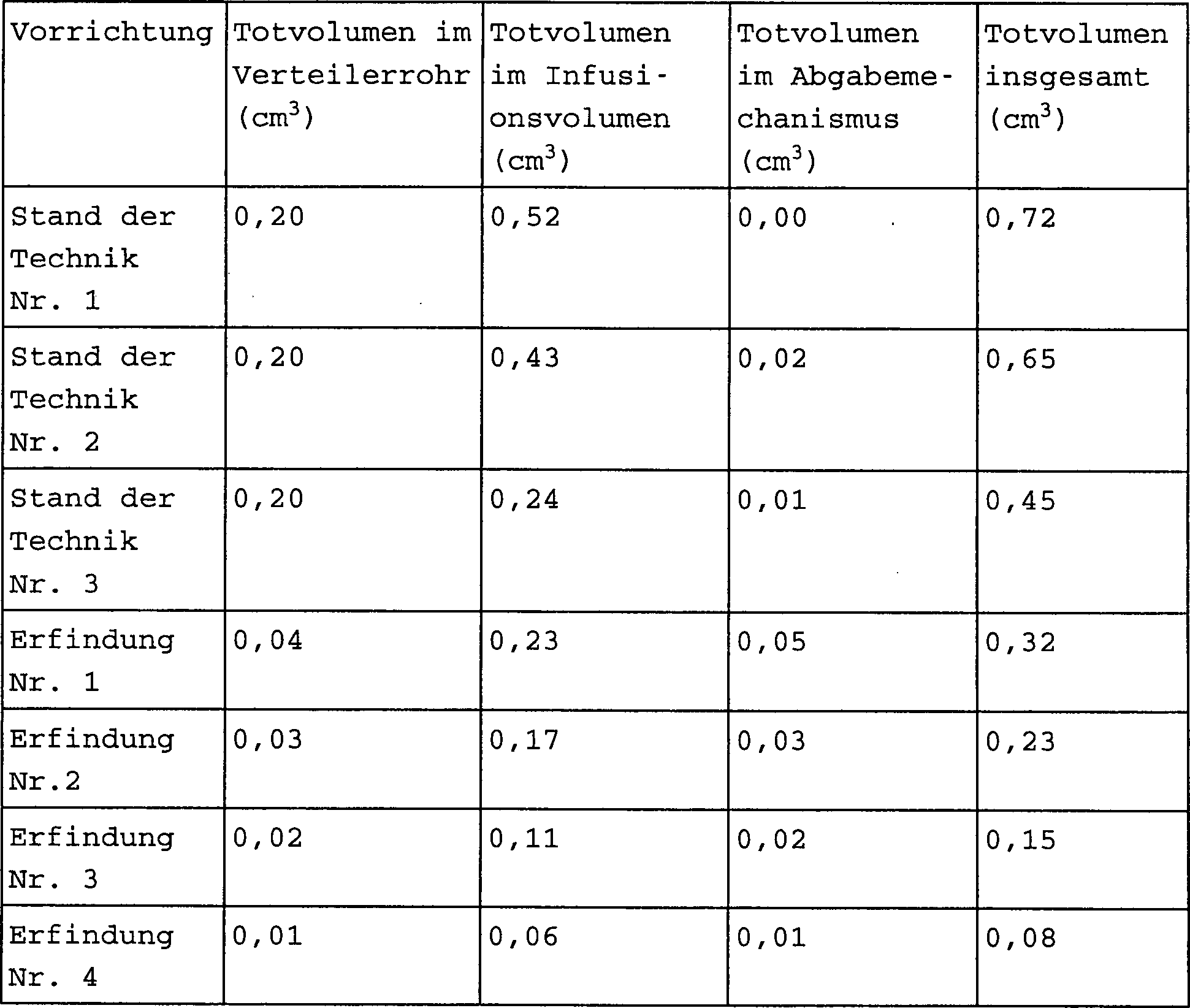
und idealerweise von weniger als 0,08 cm3.According to the invention, a medication delivery catheter with a minimal dead volume is provided in order to keep the amount of medication remaining in the catheter after administration of the medication as small as possible. Preferably, the drug delivery catheter according to the invention has a dead volume of less than 0.32 cm 3 , including the dead volume in the proximal manifold and the rest of the catheter. The medication delivery catheter according to the invention particularly preferably has a dead volume of less than 0.15 cm 3 , and ideally less than 0.08 cm 3 .
Die Erfindung soll ferner nicht beschränkt werden
auf die Anwendung von konventionellen Kathetern per se, sondern
umfasst auch jede steuerbare, maneuvriebare Infusionsstruktur. Der
Ausdruck Katheter soll also so interpretiert werden, dass er sowohl
konventionelle Katheter als auch langgestreckte, maneuvrierbare Infusionsstrukturen
umfasst, die zum Maneuvrieren, Manipulieren, Führen und Steuern in einem Gefäß geeignet
sind.The invention is also not intended to be limited
on the use of conventional catheters per se, but
also includes any controllable, maneuverable infusion structure. The
Expression catheter should therefore be interpreted as meaning that it is both
conventional catheters as well as elongated, maneuverable infusion structures
comprises suitable for maneuvering, manipulating, guiding and controlling in one vessel
are.
Das Kathetersystem kann durch verschiedene
Lumina und Hohlräume
im Körper
geführt
werden. Der intravaskuläre
Zugang durch die femorale, brachiale und radiale Arterie wird in
Betracht gezogen, um Zielgebiete im Herzen oder im peripheren Gefäßsystem
zu erreichen. Der Katheter kann aber auch über die Aorta zur direkten
Behandlung des Herzmuskels (Myokardium) in die Herzkammern geführt werden.
Eine weitere Methode zum Erreichen der Herzkammer ist über die
Hohlvene (Vena cava). Schließlich
können
nicht-vaskuläre Leitungen
oder Lumina im Körper
zur Abgabe von Medikamenten, beispielsweise für die Krebsbehandlung, erreicht
werden.The catheter system can be different
Lumina and cavities
in the body
guided
become. The intravascular
Access through the femoral, brachial, and radial arteries becomes in
Considered to target areas in the heart or in the peripheral vasculature
to reach. The catheter can also go directly through the aorta
Treatment of the heart muscle (myocardium) to be conducted into the heart chambers.
Another method of reaching the ventricle is through
Vena cava. Finally
can
non-vascular leads
or lumina in the body
for the delivery of medication, for example for cancer treatment
become.
Erfindungsgemäß ist ein kollabierbares Arzneimittelreservoir
im Katheter enthalten, das zum Kollabieren gebracht wird, um den
Flüssigkeitsbolus
zu verabreichen.According to the invention, a collapsible drug reservoir
contained in the catheter that is collapsing around the
fluid bolus
to administer.
KURZE BESCHREIBUNG DER
ZEICHNUNGBRIEF DESCRIPTION OF THE
DRAWING
1 zeigt
einen seitlichen Schnitt durch ein Kathetersystem. 1 shows a side section through a catheter system.
2 zeigt
einen vergrößerten seitlichen
Schnitt durch einen distalen Teil des Kathetersystems. 2 shows an enlarged lateral section through a distal part of the catheter system.
3 zeigt
eine vergrößerte Ansicht
des distalen Endes eines Kathetersystems. 3 shows an enlarged view of the distal end of a catheter system.
4 zeigt
einen vergrößerten seitlichen
Schnitt durch einen distalen Teil des Kathertersystems. 4 shows an enlarged lateral section through a distal part of the catheter system.
5 zeigt
ein vergrößerten seitlichen
Schnitt durch einen distalen Teil des Kathetersystems. 5 shows an enlarged lateral section through a distal part of the catheter system.
6 zeigt
einen vergrößerten seitlichen
Schnitt durch einen distalen Teil des Kathetersystems. 6 shows an enlarged lateral section through a distal part of the catheter system.
7 zeigt
einen vergrößerten seitlichen
Schnitt durch einen distalen Teil des Kathetersystems. 7 shows an enlarged lateral section through a distal part of the catheter system.
8 zeigt
einen seitlichen Schnitt durch ein Kathetersystem. 8th shows a side section through a catheter system.
9 zeigt
einen seitlichen Schnitt durch das Kathetersystem von 8, mit einer modifizierten
Ausbildung des Flüssigkeitsreservoirs. 9 shows a side section through the catheter system of 8th , with a modified design of the liquid reservoir.
10.
zeigt einen seitlichen Schnitt durch ein Kathetersystem mit einer
Zwei-Kolben-Anordnung. 10 , shows a side section through a catheter system with a two-piston arrangement.
11 zeigt
einen seitlichen Schnitt durch ein Kathetersystem mit einer gegabelten
Kolben-Anordnung. 11 shows a side section through a catheter system with a bifurcated piston arrangement.
12 zeigt
einen seitlichen Schnitt durch ein Kathetersystem mit einem Ventil
und einer eingreifbaren Ventilsitzanordnung. 12 shows a side section through a catheter system with a valve and an engageable valve seat assembly.
13A zeigt
einen seitlichen Schnitt durch ein Kathetersystem. 13A shows a side section through a catheter system.
13B zeigt
einen seitlichen Schnitt mit einer alternativen Kanal-Ballonstruktur. 13B shows a side section with an alternative channel balloon structure.
13C zeigt
einen Schnitt entlang der Linie C-C von 13B. 13C shows a section along the line CC of 13B ,
13D zeigt
einen Schnitt entlang der Linie D-D von 13B. 13D shows a section along the line DD of 13B ,
14A–14D erläutern eine Spritze und ein
proximales Verteilerrohr (manifold). 14A - 14D explain a syringe and a proximal manifold.
15 und 15B zeigen einen seitlichen
Schnitt durch einen Katheter bzw. eine Seitenansicht eines Kolbens. 15 and 15B show a side section through a catheter and a side view of a piston.
16A–16D erläutern die Arbeitsweise eines
Katheters mit einem kollabierbaren Reservoir gemäß der Erfindung. 16A - 16D explain the operation of a catheter with a collapsible reservoir according to the invention.
17A–17D erläutern die Arbeitsweise eines
Katheters mit einem kollabierebaren Reservoir nach einem anderen
Gesichtspunkt der Erfindung. 17A - 17D illustrate the operation of a catheter with a collapsible reservoir according to another aspect of the invention.
18A–18H erläutern in schematischer Form
eine weitere Ausführungsform
der vorliegenden Erfindung mit einer kollabierbaren Membran. 18A - 18H explain in schematic form a further embodiment of the present invention with a collapsible membrane.
Es sei bemerkt, dass die 1 bis 15B nicht beanspruchte Varianten des
Gegenstandes der vorliegenden Erfindung erläutern.It should be noted that the 1 to 15B explain non-claimed variants of the subject matter of the present invention.
DETAILBESCHREIBUNG
DER BEVORZUGTEN AUSFÜHRUNGSFORMENLONG DESCRIPTION
OF THE PREFERRED EMBODIMENTS
1 zeigt
einen seitlichen Schnitt durch ein Kathetersystem 10, das
nicht Teil der Erfindung ist. Das Kathetersystem 10 enthält einen
Katheter mit einem distalen Ende 14, einem proximalen Ende 16 und
ein durchgehendes Lumen 18. Bei der in 1 dargestellten Ausführungsform ist das distalen
Ende 14 einfach ein offenes Ende, das eine distale Öffnung 20 bildet,
und das proximale Ende 16 ist in beliebiger Weise mit einem
proximalen Verteilerrohr (manifold) 22 verbunden. 1 shows a side section through a catheter system 10 which is not part of the invention. The catheter system 10 contains a catheter with a distal end 14 , a proximal end 16 and a continuous lumen 18 , At the in 1 The embodiment shown is the distal end 14 just an open end that has a distal opening 20 forms, and the proximal end 16 is in any way possible with a proximal manifold 22 connected.
Das Verteilerrohr 22 hat
vorzugsweise ein durchgehendes Lumen 24, das mit dem Lumen 18 koaxial ist.
Das Lumen 24 steht vorzugsweise auch in Fluidverbindung
mit dem Lumen 18. Das System 10 enthält vorzugsweise
auch einen Kolbenstab 26. Der Kolbenstab 26 ist
vorzugsweise ein langgestrecktes Element, das sich von einem proximalen
Ende 28 (welches sich vorzugsweise in einen Bereich proximal
zum Verteilerrohr 22 erstreckt) zu einem distalen Ende 30 erstreckt,
das sich vorzugsweise in der Nähe
des distalen Endes 40 des Katheters 12 befindet.
Der Kolbenstab 26 hat vorzugsweise einen Außendurchmesser,
der etwas kleiner ist als der Innendurchmesser des Lumens 18.
Der Kolbenstab 26 ist vorzugsweise auch gleitend im Lumen 18 angeordnet,
so dass er einer Richtung gleiten kann, die im Allgemeinen parallel
zu der Längsachse
des Katheters 18 ist, wie es durch den Pfeil 32 angedeutet
ist.The manifold 22 preferably has a continuous lumen 24 that with the lumen 18 is coaxial. The lumen 24 is preferably also in fluid communication with the lumen 18 , The system 10 preferably also includes a piston rod 26 , The piston rod 26 is preferably an elongated member extending from a proximal end 28 (which is preferably in an area proximal to the manifold 22 extends) to a distal end 30 extends, preferably near the distal end 40 of the catheter 12 located. The piston rod 26 preferably has an outer diameter that is slightly smaller than the inner diameter of the lumen 18 , The piston rod 26 is preferably also sliding in the lumen 18 arranged so that it can slide in a direction generally parallel to the longitudinal axis of the catheter 18 is like it by the arrow 32 is indicated.
Der Kolbenstab 26 ist für eine hin-
und herbewegbar im Lumen 18 gehalten, und zwar aufgrund
seiner äußeren Abmessungen
im Verhältnis
zu dem inneren Abmessungen des Lumens 18, sowie durch die
Dichtungsanordnung 34. Die Dichtungsanordnung 34 ist
vorzugsweise eine O-Ring-Dichtung, die das Innere des Lumens 18 von
dem äußeren des
Systems 10 durch das proximale Ende des Verteilerrohrs 22 flüssigkeitsdicht abschließt. Die
Dichtungsanordnung 34 enthält also vorzugsweise einen
O-Ring 36, der sich in einer im Allgemeinen ringförmigen Vertiefung 38 im
Lumen 34 des Verteilerrohrs 22 befindet. Der O-Ring 36 ist
vorzugsweise aus einem üblichen
Abdichtmaterial, wie Silikonkautschuk, gebildet und ist mittels
eines geeigneten Klebstoffs in der ringförmigen Vertiefung 38 gehalten.The piston rod 26 is for a reciprocating in the lumen 18 held because of its outer dimensions in relation to the inner dimensions of the lumen 18 , as well as through the sealing arrangement 34 , The sealing arrangement 34 is preferably an O-ring seal that covers the inside of the lumen 18 from the outside of the system 10 through the proximal end of the manifold 22 seals liquid-tight. The sealing arrangement 34 therefore preferably contains an O-ring 36 that is in a generally annular recess 38 in the lumen 34 the manifold 22 located. The o-ring 36 is preferably formed from a conventional sealing material such as silicone rubber and is in the annular recess by means of a suitable adhesive 38 held.
Das distale Ende 30 des
Stabs 26 wirkt in der in 1 dargestellten
Stellung vorzugsweise mit dem Innenumfang des distalen Endes 14 des
Katheters 12 zusammen, um eine Boluskammer 37 zur
Aufnahme eines Bolus aus Behandlungsmaterial zu bilden. Das in der
Kammer 37 enthaltene Behandlungsmaterial kann ein Medikament,
ein Wachstumsfaktor, ein gentechnologisches Material, eine radioaktive
Flüssigkeit
für die Restenose
oder Krebsbehandlung, ein klumpenlösendes Mittel oder ein anderes
gewünschtes
fluides oder flüssiges
Material sein. Das Material kann auch unter hohem Druck mit hoher
Geschwindigkeit injiziert werden, um Klumpen (Thromben) mechanisch
aufzubrechen. Wie in der nachstehenden Beschreibung noch näher erläutert ist,
wird das durch das System 10 verabreichte Material zu einer
gewünschten
Stelle im Körper
durch Hin- und Herbewegung des Stabes 26 im Lumen 18 gebracht.The distal end 30 of the staff 26 acts in the 1 shown position preferably with the inner circumference of the distal end 14 of the catheter 12 together to form a bolus chamber 37 to form a bolus of treatment material. That in the chamber 37 The treatment material contained may be a medicament, a growth factor, a genetic engineering material, a radioactive liquid for restenosis or cancer treatment, a lump-removing agent or another desired fluid or liquid material. The material can also be injected at high speed under high pressure to mechanically break up lumps (thrombi). As will be explained in more detail in the description below, this is achieved by the system 10 administered material to a desired location in the body by reciprocating the rod 26 in the lumen 18 brought.
Das proximale Ende 28 des
Kolbenstabs 26 ist vorzugsweise in einer geeigneten Weise
geformt, so dass der Benutzer den Stab im Lumen 18 leicht
ergreifen und hin- und herbewegen kann. Bei einer Ausführungsform
ist eine verschraubbare Verbindung zwischen dem proximalen Ende 28 des
Stabs 26 und dem Verteilerrohr 22 vorgesehen.
Auf diese Weise kann der Benutzer den Stab 26 drehen, um
entweder eine proximale oder eine distale Reziprokbewegung im Lumen 18 zu
erzeugen. Nach einer weiteren bevorzugten Ausführungsform ist ein Freigabemechanismus
vorgesehen, so dass der Schraubeingriff zwischen dem Stab 26 und dem
Verteilerrohr 22 gelöst
werden kann, wodurch der Stab 26 einfach geschoben oder
gezogen werden kann und somit in Längsrichtung schneller bewegt
werden kann. Dann wird zur Feineinstellung des Stabes 26 die Schraubverbindung
wieder aktiviert und der Stab 26 wird gedreht um eine Längsbewegung
zu bewirken. Es kann auch eine elektromechanische (z. B. durch ein
Solenoid) Betätigung
des Stabes 26 erfolgen.The proximal end 28 of the piston rod 26 is preferably shaped in a suitable manner so that the user can insert the rod into the lumen 18 can easily grasp and move back and forth. In one embodiment there is a screwable connection between the proximal end 28 of the staff 26 and the manifold 22 intended. This way the user can control the rod 26 rotate to either proximal or distal reciprocal motion in the lumen 18 to create. According to a further preferred embodiment, a release mechanism is provided so that the screw engagement between the rod 26 and the manifold 22 can be solved, causing the rod 26 can be easily pushed or pulled and thus can be moved faster in the longitudinal direction. Then the rod is fine-tuned 26 the screw connection is reactivated and the rod 26 is rotated to cause a longitudinal movement. There may also be an electromechanical (e.g. solenoid) actuation of the rod 26 respectively.
In jedem Fall kann der Katheter 12 aus
einem geeigneten Material gebildet sein, das durch das gewünschte Gefäßsystem
geführt
und zu einer Behandlungsstelle im Körper gebrachtführt werden
kann. Deshalb wird der Katheter 12 im Betrieb vor dem Einführen in
das Gefäßsystem
vorzugsweise mit einer Lösung, z.
B. einer Kochsalzlösung
gefüllt,
so dass alle Bereiche zwischen dem Stab 26 und der Innenwand
des Lumens 18 mit der flüssigen Lösung gefüllt sind, um jegliches Totvolumen
im Lumen 18 zu vermeiden. Dann wird ein Therapeutikum oder
ein anderes fluides Material in das distale Ende 14 des
Katherter 18 eingebracht. Dies kann beispielsweise durch
Bewegen des Stabes 26 in eine Stellung erfolgen, in der
sein distales Ende 30 etwa koterminal zur Öffnung 22 im
Lumen 18 des Katheters 12 ist. Dann wird das distale
Ende 14 des Katheters 12 in die in das Gefäßsystem
einzuführende
flüssige
Lösung
gebracht, und der Stab 26 wird proximal in eine gewünschte Stellung
gezogen. Beim proximalen Ziehen des Stabes 26 wird in der
Kammer 37 des Katheters 12 ein Vakuum erzeugt,
wodurch ein Teil der in die Kammer 37 des Katheters 12 einzuführenden
flüssigen
Lösung angesaugt
wird. Nach einer bevorzugten Ausführungsform sind sichtbare Marken
am proximalen Ende 28 des Stabes 26 vorgesehen,
um dem Benutzer zu zeigen, dass das Gesamtvolumen der flüssigen Lösung, das
in das distale Ende 14 des Katheters 12 gezogen
wurde, auf der proximalen Entfernung des Stabes 26 entspricht.In any case, the catheter 12 be formed from a suitable material that can be guided through the desired vascular system and brought to a treatment site in the body. That is why the catheter 12 during operation, preferably with a solution, e.g. B. a saline solution, so that all areas between the rod 26 and the inner wall of the Lu mens 18 filled with the liquid solution to any dead volume in the lumen 18 to avoid. Then a therapeutic or other fluid material is placed in the distal end 14 of the Katherter 18 brought in. This can be done, for example, by moving the rod 26 be done in a position in which its distal end 30 about the terminal for opening 22 in the lumen 18 of the catheter 12 is. Then the distal end 14 of the catheter 12 brought into the liquid solution to be introduced into the vascular system, and the rod 26 is pulled proximally into a desired position. When pulling the rod proximally 26 is in the chamber 37 of the catheter 12 a vacuum is created, causing part of the in the chamber 37 of the catheter 12 liquid solution to be introduced is sucked in. According to a preferred embodiment, there are visible marks at the proximal end 28 of the staff 26 provided to show the user that the total volume of liquid solution is in the distal end 14 of the catheter 12 was pulled on the proximal distance of the rod 26 equivalent.
Nachdem der Katheter 12 mit
der Behandlungslösung
gefüllt
wurde, wird das distale Ende des Katheters 12 durch das
Gefäßsystem
bewegt und in der Nähe
einer gewünschten
Behandlungsstelle positioniert. Dies kann auf verschiedene bekannte
Weise erfolgen. Beispielsweise kann das distale Ende 14 des
Katheters 12 als scharfe Spitze ausgebildet sein, die dazu
verwendet werden kann, um die Haut zu durchstoßen und in das gewünschte Gefäß einzudringen.
Weiterhin kann eine gesonderte Schneidvorrichtung verwendet werden, die
im Zusammenhang mit dem (zum Beispiel über die Spitze des) Katheters) 12 verwendet
wird, um den Katheter 12 in das gewünschte Gefäß einzuführen. Weiterhin können zusammen
mit dem Katheter 12 übliche Führungsdraht-
oder Führungskatheter-Anordnungen
verwendet werden, um den Katheter 12 an eine gewünschte Stelle
im Gefäßsystem
zu führen.
Die Verwendung eines Führungsdrahtes
mit dem Katheter 12 erfolgt vorzugsweise dadurch, dass
entweder ein vom Lumen 18 getrenntes Lumen im Katheter 12 vorgesehen ist, über das
der Katheter 12 den Führungsdraht
führen
kann. Der Katheter 12 kann aber auch als Austauschkatheter
für eine
einzige Bediehungsperson gebildet sein, welcher ein distales Führungsdrahtrohr
zum Führen über den
Führungsdraht
enthält.After the catheter 12 has been filled with the treatment solution, the distal end of the catheter 12 moved through the vascular system and positioned near a desired treatment site. This can be done in various known ways. For example, the distal end 14 of the catheter 12 be formed as a sharp tip that can be used to pierce the skin and penetrate the desired vessel. Furthermore, a separate cutting device can be used, which in connection with the (for example over the tip of the) catheter) 12 used to the catheter 12 insert into the desired vessel. Furthermore, together with the catheter 12 Common guidewire or guiding catheter arrangements are used to secure the catheter 12 to a desired location in the vascular system. The use of a guidewire with the catheter 12 is preferably done by either one of the lumens 18 separate lumen in the catheter 12 is provided over which the catheter 12 can guide the guidewire. The catheter 12 can also be formed as an exchange catheter for a single relative, which contains a distal guidewire tube for guiding over the guidewire.
In jedem Fall wird das distale Ende
des Katheters 12 in geeigneter Weise sichtbar gemacht oder
nach anderen Positioniermethoden bewegt, bis es in der Nähe der zu
behandelten Stelle steht.In either case, the distal end of the catheter 12 appropriately visualized or moved by other positioning methods until it is close to the area to be treated.
Sobald es in geeigneter Weise positioniert
ist, bewegt der Benutzer den Stab 26 distal, so dass das distale
Ende 30 des Stabes 26 einen positiven Druck in
der Kammer 37 des Lumens am distalen Ende des Katheters 12 erzeugt.
Durch diesen positiven Druck wird das flüssige Behandlungsmaterial aus
der distalen Öffnung 20 im
Katheter 12 gedrückt,
so dass es an der gewünschten
Stelle abgegeben wird.Once properly positioned, the user moves the wand 26 distal, so the distal end 30 of the staff 26 a positive pressure in the chamber 37 of the lumen at the distal end of the catheter 12 generated. This positive pressure removes the liquid treatment material from the distal opening 20 in the catheter 12 pressed so that it is delivered to the desired location.
Das Volumen der Kammer 37,
das durch den Innenumfang des Katheters 12 und der distalen
Spitze des Stabes 26 bestimmt ist, kann weniger als oder
gleich etwa einen Milliliter betragen. Man erkennt also, dass der
Katheter 12 dazu verwendet werden kann, um einen sehr kleinvolumigen
Bolus eines Medikaments oder eines anderen therapeutischen Materials
direkt an eine gewünschte
Behandlungsstelle innerhalb des Körpers abzugeben, wobei eine
Transluminaltechnik angewendet wird.The volume of the chamber 37 through the inner circumference of the catheter 12 and the distal tip of the rod 26 is less than or equal to about one milliliter. So you can see that the catheter 12 can be used to deliver a very small bolus of medication or other therapeutic material directly to a desired treatment site within the body using a transluminal technique.
Die speziellen Materialien, die für das Kathetersystem 10 verwendet
werden können,
können
alle geeigneten handelüblichen
Materialen umfassen. Beispielsweise ist das Verteilerrohr 22 vorzugsweise
aus einem spritzgegossenen Polycarbonat hergestellt. Die Vertiefung 38,
in welcher der O-Ring 36 sitzt, ist vorzugsweise eine Vertiefung
mit einem Durchmesser von etwa 0,312 cm (0,123 inch), die im Verteilerrohr 22 gebildet ist,
und der Innendurchmesser des Lumens 24 im Verteilerrohr 22 beträgt vorzugsweise
0,107 cm (0,042 inch). Der Katheter 12 kann aus mehreren
Abschnitten oder nur aus einem Abschnitt gebildet sein. Der Katheter 12 kann
auch aus allen geeigneten Materialen hergestellt sein, was von den
gewünschten
Gebrauchseigenschaften abhängt.
Beispielsweise kann der Katheter 12 aus einem extrudiertem
Polymerrohr, aus einem Spritzenrohr aus Edelstahl oder aus einem
Verbundmaterial, z. B. einem Edelstahlgeflecht in Polyimid sein.
Um unterschiedliche Eigenschaften entlang seiner Länge zu erzeugen,
kann der Katheter unterschiedliche Durchmesser haben oder unterschiedliche
Strukturen umfassen. Beispielsweise kann der Katheter 12 einen
proximalen Verbundabschnitt, kombiniert mit einem distalen polymeren
Abschnitt enthalten. Andere geeignete Ausbildungen können ebenfalls
verwendet werden.The special materials for the catheter system 10 can be used, can comprise all suitable commercially available materials. For example, the manifold 22 preferably made of an injection molded polycarbonate. The deepening 38 in which the O-ring 36 is preferably a recess approximately 0.312 cm (0.123 inch) in diameter in the manifold 22 is formed, and the inner diameter of the lumen 24 in the manifold 22 is preferably 0.107 cm (0.042 inch). The catheter 12 can be formed from several sections or from only one section. The catheter 12 can also be made of all suitable materials, depending on the desired properties. For example, the catheter 12 from an extruded polymer tube, from a stainless steel syringe tube or from a composite material, e.g. B. a stainless steel mesh in polyimide. To create different properties along its length, the catheter can have different diameters or comprise different structures. For example, the catheter 12 a proximal composite section combined with a distal polymeric section. Other suitable training can also be used.
Der Stab 26 ist vorzugsweise
aus einem Draht aus Edelstahl hergestellt, der von einem KynarWZ-Rohr umgeben ist. Der Draht aus Edelstahl
hat vorzugsweise einen Druckmesser von etwa 0.048 cm (0,019 inch) und
eine Länge
von etwa 127 cm (50 inch). Das Rohr, das den Draht umgibt, hat vorzugsweise
einen Außendurchmesser
von etwa 0,097 cm (0,038 inch) und einen Innendurchmesser von 0,051
cm (0,020 inch). Wenn der Stab 26 vollständig in
der distalen Richtung bewegt wurde, ist er vorzugsweise so lang,
dass sein distales Ende 30 mit dem distalen Ende 14 im
Katheter 12 abschließt.
Es können
gegebenenfalls positive Anschläge (nicht
dargestellt) am distalen Ende 40 des Katheters 12 vorgesehen
sein, um die distale Bewegung des Stabes 26 zu begrenzen.The rod 26 is preferably made from stainless steel wire surrounded by a Kynar WZ tube. The stainless steel wire preferably has a pressure gauge of about 0.048 cm (0.019 inch) and a length of about 127 cm (50 inch). The tube surrounding the wire is preferably about 0.097 cm (0.038 inch) in outside diameter and 0.051 cm (0.020 inch) in inside diameter. If the rod 26 has been moved completely in the distal direction, it is preferably so long that its distal end 30 with the distal end 14 in the catheter 12 concludes. There may be positive stops (not shown) at the distal end 40 of the catheter 12 be provided to the distal movement of the rod 26 to limit.
Im Allgemeinen können Verbindungen zwischen
den verschiedenen polymeren Komponenten mit Hilfe von geeigenten
medizinischen Klebstoffen oder thermischen Bindemitteln hergestellt
werden, die dem Fachmann sämtlich
bekannt sind. Verbindungen zwischen metallischen Bestandteilen werden
vorzugsweise durch Löten,
Hartlöten,
Schweißen
oder nach anderen geeigneten Methoden hergestellt.In general, connections between
the various polymeric components with the help of suitable
medical adhesives or thermal binders
be the expert all
are known. Connections between metallic components
preferably by soldering,
Brazing,
welding
or produced by other suitable methods.
2 zeigt
eine vergrößerte Ansicht
eines distalen Endabschnitts 14 des Katheters 12.
Einige Bestandteile in 2 sind ähnlich denen
von 1, weshalb sie entsprechend
nummeriert sind. 2 zeigt
jedoch, dass der Stab 26 nicht nur ein distales Ende 30 hat,
sondern dass ein Stempel 40 mit dem distalen Ende 30 des
Stabes 26 verbunden ist. Der Stempel 24 hat einen
Außendurchmesser,
der etwa gleich dem oder etwas kleiner als der Innendurchmesser
des Lumens 18 ist. Wenn also der Stab 26 in distaler
Richtung bewegt wird, wirken der Stempel 40 und der Stab 26 weitgehend
wie eine konventionelle Spritze, indem die distale Kammer 37,
die durch das distale Ende 14 des Katheters 12 und
den Stempel 40 begrenzt ist, unter Druck gesetzt wird.
Dadurch wird der Bolus des Behandlungsmaterials durch die distale Öffnung 20 im
Katheter 12 nach außen
gedrückt.
Da jedoch der Stempel 40 vorgesehen ist, braucht der äußere Umfang
des restlichen des Betätigungsstabes
nicht etwa gleich oder gerade kleiner als der Innenumfang des Lumens 18 zu
sein. Stattdessen kann er viel kleiner sein. Dadurch werden die
Reibungskräfte,
die auf den Stab 26 während
seiner Hin- und Herbewegung im Lumen 18 einwirken, stark
reduziert. Es sei darauf hingewiesen, dass der Stempel 40 ein
getrenntes Element sein kann, das an dem distalen Ende 30 des
Stabes 26 befestigt sein kann, oder er kann mit dem Stab 26 eine
Einheit bilden, einfach indem das distale Ende 30 des Stabes 26 verbreitert
wird. 2 shows an enlarged view of a distal end portion 14 of the catheter 12 , Some be components in 2 are similar to those of 1 which is why they are numbered accordingly. 2 shows, however, that the staff 26 not just a distal end 30 but has a stamp 40 with the distal end 30 of the staff 26 connected is. The Stamp 24 has an outer diameter that is approximately equal to or slightly smaller than the inner diameter of the lumen 18 is. So if the staff 26 is moved in the distal direction, the stamp act 40 and the staff 26 largely like a conventional syringe by the distal chamber 37 through the distal end 14 of the catheter 12 and the stamp 40 is limited, is put under pressure. This will cause the bolus of treatment material to pass through the distal opening 20 in the catheter 12 pushed outwards. However, since the stamp 40 is provided, the outer circumference of the rest of the actuating rod does not need to be approximately the same or just smaller than the inner circumference of the lumen 18 to be. Instead, it can be much smaller. This will reduce the frictional forces on the rod 26 during its float in the lumen 18 act, greatly reduced. It should be noted that the stamp 40 can be a separate element at the distal end 30 of the staff 26 can be attached or it can be attached to the rod 26 form a unit simply by placing the distal end 30 of the staff 26 is widened.
3 zeigt
eine weitere vergrößerte Ansicht
des distalen Endes des Stabes 26. Einige Elemente sind ähnlich wie
die von 12 und sind
in ähnlicher
weise nummeriert. Die in 3 dargestellte
Ausführungsform enthält jedoch
statt des einfachen Stempels 40 einen Stempelkopf 42.
Der Stempelkopf 42 enthält
ein Paar Scheiben 44 und 46, die um einen äußeren Umfang
des distalen Endes 30 des Stabes 26 angebracht
sind. Die Scheiben 44 und 46 sind vorzugsweise
durch einen O-Ring 48 voneinander getrennt, der aus Silikon
oder einem anderen geeigneten Material gebildet ist, und der so
groß ist,
dass das Lumen 18 flüssigkeitsdicht
abgedichtet ist. Die Scheiben 44 und 46 sind ebenfalls
vorzugsweise an einem Silikonkautschukmaterial oder einem anderen
geeigneten Material geformt, können
aber mit dem Stab 26 eine Einheit bilden. 3 shows another enlarged view of the distal end of the rod 26 , Some elements are similar to that of 12 and are similarly numbered. In the 3 illustrated embodiment, however, contains instead of the simple stamp 40 a stamp head 42 , The stamp head 42 contains a pair of discs 44 and 46 that are around an outer circumference of the distal end 30 of the staff 26 are attached. The disks 44 and 46 are preferably through an O-ring 48 separated from each other, which is made of silicone or another suitable material, and which is so large that the lumen 18 is sealed liquid-tight. The disks 44 and 46 are also preferably molded on a silicone rubber material or other suitable material, but can be made with the rod 26 form a unit.
4 zeigt
einen vergrößerten seitlichen
Schnitt einer Variante von Katheter 12. Einige Elemente
sind mit denen von 2 identisch
weshalb sie auch entsprechend nummeriert sind. Anstelle einer einfachen
distalen Öffnung
im distalen Ende des Katheters 12 zeigt 4 eine trennbare Abdichtung im distalen Ende 14. Die
trennbare Abdichtung 50 enthält vorzugsweise ein Kautschuk-
oder Polymermaterial, das in das distale Ende 14 des Katheters 12 eingesetzt
und damit mit Hilfe eines geeigneten Klebstoffs verbunden ist. 4 shows an enlarged side section of a variant of catheter 12 , Some elements are the same as those of 2 identical which is why they are numbered accordingly. Instead of a simple distal opening in the distal end of the catheter 12 shows 4 a separable seal in the distal end 14 , The separable seal 50 preferably contains a rubber or polymeric material that extends into the distal end 14 of the catheter 12 used and connected with the help of a suitable adhesive.
Die trennbare Abdichtung 50 enthält vorzugsweise
eine Naht 52. Die Naht 52 wird vorzugsweise dadurch
gebildet, dass die Oberflächen
der Abdichtung 50 aneinander anstoßen, wobei diese Teile jedoch
nicht durch Klebstoff oder anderweitig miteinander verbunden sind
(ausgenommen durch Reibung). Diese Anordnung ermöglicht die Einführung einer üblichen
Nadel mit kleinem Durchmesser, die mit einer, die Behandlungslösung enthaltenen
Spritze verbunden ist, in das distale Ende 14 (und somit
in die Kammer 37) des Katheters 12 durch die Naht 52.
Die Behandlungslösung
kann also in die Kammer 37 des Katheters 12 injiziert
werden, wenn der Stempel in proximaler Richtung zurückgezogen
wird, um die Behandlungslösung
anzusaugen.The separable seal 50 preferably contains a seam 52 , The seam 52 is preferably formed by the surfaces of the seal 50 abut each other, but these parts are not bonded to each other by glue or otherwise (except by friction). This arrangement enables a conventional small diameter needle connected to a syringe containing the treatment solution to be inserted into the distal end 14 (and thus into the chamber 37 ) of the catheter 12 through the seam 52 , The treatment solution can therefore be in the chamber 37 of the catheter 12 be injected when the plunger is withdrawn in the proximal direction to draw in the treatment solution.
Sobald das distale Ende 14 des
Katheters 12 an der Behandlungsstelle im Gefäßsystem
platziert ist, bewirkt eine distale Bewegung des Stabes 26,
dass der Stempel 40 einen Druck hinter der Abdichtung 50 erzeugt,
wodurch sich die Abdichtung 50 an der Naht 52 trennt
und so die Behandlungslösung
an der gewünschten
Stelle freigibt. Bei einer anderen bevorzugten Ausführungform
ist die Abdichtung 50 vom Typ einer rollenden Membran oder
von einem anderen Typ einer Abdichtungsanordnung.Once the distal end 14 of the catheter 12 placed at the treatment site in the vascular system causes distal movement of the rod 26 that the stamp 40 a pressure behind the seal 50 generated, which causes the seal 50 at the seam 52 separates and thus releases the treatment solution at the desired location. In another preferred embodiment, the seal is 50 rolling membrane type or other type of sealing arrangement.
5 zeigt
einen vergrößerten seitlichen
Schnitt einer anderen Variante des Katheters 12. Ähnliche Elemente
sind ähnlich
wie in den vorstehenden Figuren nummeriert. 5 zeigt jedoch, dass die distale Spitze des
Katheters 12 mit einer Nadel mit mehreren Öffnungen 54 versehen
ist. Die Öffnungen 54 ermöglichen
es, dass die Behandlungslösung 37 in
das distale Ende 14 des Katheters 12 gezogen und
durch dessen distales Ende herausgedrückt wird. 5 shows an enlarged side section of another variant of the catheter 12 , Similar elements are numbered similarly to those in the previous figures. 5 shows, however, that the distal tip of the catheter 12 with a needle with multiple openings 54 is provided. The openings 54 allow the treatment solution 37 into the distal end 14 of the catheter 12 pulled and pushed out through its distal end.
6 ist ähnlich wie 5, ausgenommen jedoch, dass
statt der gleichmäßig beabstandeten Öffnungen 54 an
der distalen Spitze des Katheters 12 der distale Spitzen-
oder Düsenbereich
mit seitlichen Öffnungen 56 versehen
ist, die es ermöglichen,
dass die Behandlungslösung
in der Kammer 37 gezielt in der Richtung, in der die seitlichen Öffnungen
angeordnet sind, verabreicht werden kann. 6 is similar to 5 , except that instead of the equally spaced openings 54 at the distal tip of the catheter 12 the distal tip or nozzle area with side openings 56 is provided, which allow the treatment solution in the chamber 37 can be administered specifically in the direction in which the side openings are arranged.
In 7 sind ähnliche
Bestandteile wie in den früheren
Figuren ähnlich
nummeriert. Das distale Ende des Katheters 12 ist jedoch
kein festes Element mit Öffnungen,
sondern ist als Teil einer porösen
Nadel 58 ausgebildet. Der poröse Nadelteil 58 kann
als mikroporöse
Membran, als selektiv poröse
Membran oder als ein anderes geeignetes poröses oder kapillares Material
ausgebildet sein, das zur Einführung
der Behandlungslösung
aus der Kammer 37 an die Behandlungsstelle geeignet ist.In 7 components similar to those in the previous figures are numbered similarly. The distal end of the catheter 12 is not a solid element with openings, but is part of a porous needle 58 educated. The porous needle part 58 can be designed as a microporous membrane, as a selectively porous membrane or as another suitable porous or capillary material which is used to introduce the treatment solution from the chamber 37 is suitable for the treatment site.
8 zeigt
einen seitlichen Schnitt durch ein Kathetersystem 60. Einige
Bestandteile sind ähnlich
denen von 1 bis 7, weshalb sie auch ähnlich nummmeriert
sind. Der Katheter 12 ist jedoch auch mit einem Reservoir 62 für die Behandlungsflüssigkeit
vorgesehen, das durch die Wand 64 begrenzt ist, welche
vorzugsweise um einen äußeren Teil
des Katheters 12 angeordnet ist. Das Reservoir 62 erstreckt
sich von einem distalen Ende 66, das unmittelbar neben
der Anwendungsspitze (oder Düse) 68 angeordnet
ist, zu einem proximalen Ende 70, das mit einem geeigenten
Verbindungsstück
zur Aufnahme der Behandlungslösung
versehen ist. 8th shows a side section through a catheter system 60 , Some components are similar to those of 1 to 7 which is why they are numbered similarly. The catheter 12 is also with a reservoir 62 provided for the treatment liquid that goes through the wall 64 is limited, which is preferably around an outer part of the catheter 12 is arranged. The reservoir 62 extends from a distal end 66 which is immediately next to the application tip (or nozzle) 68 is arranged to a proximal end 70 , which is provided with a suitable connector for receiving the treatment solution.
Bei der Anwendung wird die Behandlungslösung vorzugsweise
mit Hilfe einer Standardspritze durch den proximalen Teil 70 des
Reservoirs 62 injiziert. Ein Klappenventil 72 ist
vorzugsweise am distalen Ende 66 des Reservoirs 62 angeordnet,
um das Lumen 18 im Katheter 12 fluidmäßig vom
Reservoir 62 zu trennen. Das Klappenventil 72 kann
so angeordnet sein, dass es im Allgemeinen in einer Richtung, die
durch den Pfeil 74 angedeutet ist, schwenkt. Es ist durch
das Gelenk 76 an der Wand des Katheters 12 angelenkt.
Das Klappenventil 72 hat ein distales Ende 78,
das auf einem positiven Anschlag 80 auf der Innenseite
des Lumens 18 des Katheters 12 aufliegt.When used, the treatment solution is preferably administered using a standard syringe the proximal part 70 of the reservoir 62 injected. A flap valve 72 is preferably at the distal end 66 of the reservoir 62 arranged to the lumen 18 in the catheter 12 fluidly from the reservoir 62 to separate. The flap valve 72 can be arranged so that it is generally in a direction indicated by the arrow 74 is indicated, pivots. It is through the joint 76 on the wall of the catheter 12 hinged. The flap valve 72 has a distal end 78 that on a positive stop 80 on the inside of the lumen 18 of the catheter 12 rests.
Wenn also der Stempel 40 proximal
bewegt wird, wird ein Vakuum oder ein Unterdruck in der Kammer 37 relativ
zum Reservoir 62 erzeugt. Dies bewirkt, dass das Klappenventil 72 nach
oben angehoben wird, so dass Flüssigkeit
aus dem Reservoir 62 in die Kammer 37 strömen kann.
Wenn der Stempel 40 dann distal bewegt wird, wird im Lumen 18 relativ
zum Reservoir 82 ein hoher Druck erzeugt, so dass sich
das Klappenventil 70 schließt und das distale Ende des
Klappenventils 72 an den positiven Anschlag 80 anschlägt.So if the stamp 40 is moved proximally, there is a vacuum or a vacuum in the chamber 37 relative to the reservoir 62 generated. This causes the flap valve 72 is lifted upwards, so that liquid from the reservoir 62 into the chamber 37 can flow. If the stamp 40 then moved distally is in the lumen 18 relative to the reservoir 82 generates a high pressure so that the flap valve 70 closes and the distal end of the flapper valve 72 to the positive stop 80 strikes.
Wenn der Stempel 40 weiter
distal bewegt wird, wird die Behandlungslösung in der Kammer 37 durch die
Verabreichungsspitze 68 an die gewünschte Stelle gebracht. Die
Verabreichungsspitze 68 kann mit sehr kleinen Öffnungen
oder Poren oder Ventilöffnungen
versehen sein, so dass ein größerer Druckunterschied
zwischen dem inneren Lumen 18 und dem Äußeren des Katheters 12 benötigt wird,
damit das flüssige
Material durch die Verabreichungsspitze 68 hindurchgeht,
als benötigt
wird, um das Klappenventil zu heben. Deshalb wird, wenn der Stempel 40 proximal
bewegt wird, das Klappenventil 72 geöffnet, um den Eintritt des
Behandlungsmaterials aus der Kammer 62 in das Lumen 18 zu
ermöglichen;
es wird aber keine Flüssigkeit
oder nur sehr wenig Flüssigkeit
von außerhalb
des Katheters 12 in das Lumen 18 gezogen. Wird
dann der Stempel 40 distal weiterbewegt, so schließt sich
das Klappenventil 72, und es wird ein ausreichend hoher
Druck in der Kammer 37 aufgebaut, so dass das Behandlungsmaterial
durch die Verabreichungsspitze 68 an die gewünschte Stelle
gelangt.If the stamp 40 is moved further distally, the treatment solution is in the chamber 37 through the administration tip 68 brought to the desired location. The administration tip 68 can be provided with very small openings or pores or valve openings, so that a larger pressure difference between the inner lumen 18 and the exterior of the catheter 12 is needed so that the liquid material passes through the administration tip 68 goes through than is required to lift the flap valve. Therefore, when the stamp 40 is moved proximally, the flap valve 72 opened to the entry of the treatment material from the chamber 62 into the lumen 18 to enable; however, there is no fluid or very little fluid from outside the catheter 12 into the lumen 18 drawn. Then the stamp 40 Moving distally, the flap valve closes 72 , and there is a sufficiently high pressure in the chamber 37 built up so that the treatment material through the administration tip 68 reached the desired location.
Man erkennt also, dass das in 8 beschriebene Kathetersystem 60 es
dem Benutzer ermöglicht, die
distale Spitze 14 des Katheters an der gewünschten
Stelle im Körper
zu positionieren, bevor die Kammer 37 mit dem Bolus des
Behandlungsmaterials gefüllt
wird, das an der Behandlungsstelle injiziert werden soll.So you can see that in 8th described catheter system 60 it allows the user to use the distal tip 14 Position the catheter at the desired location in the body before the chamber 37 is filled with the bolus of treatment material to be injected at the treatment site.
9 zeigt
ein anderes distales Ende des Katheters 12 im Kathetersystem 60. Ähnliche
Teile sind ähnlich
wie in 8 nummeriert.
Anstatt dass sich jedoch das Reservoir 62 insgesamt von
seinem distalen Ende 66 zu seinem proximalen Ende 70 erstreckt,
wird das Reservoir 62 nur an einem distalen Teil des Katheters
gehalten. Das Reservoir 62 ist ebenfalls mit einem geeigneten
Einführungsventil 82 versehen,
das zusammen mit einer üblichen
Spritze verwendet werden kann, um den Bolus des Behandlungsmaterials
in das Reservoir 62 einzuführen. Da es nicht nötig ist,
dass sich das Reservoir 62 bis ganz zum proximalen Ende
erstreckt, kann das Innenvolumen des Reservoirs sehr klein gehalten
werden. Dies erleichtert es, dass nur das benötigte Volumen des Behandlungsmaterials.
Kein zusätzliches
Material ist erforderlich, um das Innenvolumen des Reservoirs 82 zu
füllen,
da dieses Volumen so klein ist. 9 shows another distal end of the catheter 12 in the catheter system 60 , Similar parts are similar to in 8th numbered. Instead of that, however, the reservoir 62 overall from its distal end 66 to its proximal end 70 extends, the reservoir 62 only held on a distal part of the catheter. The reservoir 62 is also with a suitable insertion valve 82 provided that can be used with a conventional syringe to place the bolus of treatment material in the reservoir 62 introduce. Since it is not necessary that the reservoir 62 Extending all the way to the proximal end, the internal volume of the reservoir can be kept very small. This makes it easier to have only the required volume of treatment material. No additional material is required to fill the interior volume of the reservoir 82 to fill because this volume is so small.
10 zeigt
ein weiteres Kathetersystem 84. Das Kathetersystem 82 ist ähnlich dem
in 8 dargestellten Kathetersystem 60,
und ähnliche
Bestandteile sind ähnlich
nummeriert. Das Kathetersystem 84 enthält jedoch eine modifizierte
Form eines Behandlungsreservoirs 82. Anstatt dass das proximale
Ende 70 im proximalen Bereich endet, erstreckt sich das
proximale Ende des Reservoirs 62 im Kathetersystem 84 durch
das gesamte proximale Verteilerrohr 22 in der gleichen
Weise wie das Lumen 24. Weiterhin ist das Reservoir 62 mit
einem reziprok befestigten Stab 86 und einem Stempel 88 versehen.
Weiterhin ist der Stab dichtschließend im Verteilerrohr 22 angebracht
mit einer Hilfe einer Dichtungsanordnung 90, die ähnlich der
im Zusammenhang mit 1 diskutierten
Dichtungsanordnung 34 ist. Die proximalen Enden der Stäbe 26 und 86 können gegebenenfalls
miteinander verbunden werden oder sie können auch getrennt voneinander
sein, so dass sie von dem Benutzer getrennt betätigt werden können. 10 shows another catheter system 84 , The catheter system 82 is similar to that in 8th shown catheter system 60 , and similar components are numbered similarly. The catheter system 84 however, contains a modified form of treatment reservoir 82 , Instead of the proximal end 70 ends in the proximal area, the proximal end of the reservoir extends 62 in the catheter system 84 through the entire proximal manifold 22 in the same way as the lumen 24 , Furthermore, the reservoir 62 with a reciprocally attached rod 86 and a stamp 88 Mistake. The rod is also tightly sealed in the distributor pipe 22 attached with the help of a sealing arrangement 90 that are similar to those related to 1 discussed sealing arrangement 34 is. The proximal ends of the rods 26 and 86 can optionally be connected to one another or they can also be separate from one another so that they can be operated separately by the user.
In jedem Fall werden zum Einführen des
Bolus des Behandlungsmaterials in das Reservoir 62 der Stab 86 und
der Stempel 88 zu dem am weitesten entfernten distalen
Betätigungspunkt
geführt,
an welchem sie an die zweite Klappenventilanordnung 92 anstoßen.In any case, the bolus of the treatment material is inserted into the reservoir 62 the rod 86 and the stamp 88 to the most distal actuation point, where it connects to the second flapper valve assembly 92 nudge.
Das Klappenventil 92 ist
so angedrückt,
dass es normalerweise eine Öffnung 94 gegen
einen Innenteil 96 des distalen Endes des Reservoirs 62 verschließt. Dann
werden die distale Spitze 14 des Katheters 12 und des
Reservoirs 62 in die zu verabreichende Arzneimittellösung gebracht.
Der Stab 86 und der Stempel 88 werden dann distal
um einen bestimmten Betrag bewegt, so dass das Klappenventil 92 sich öffnet, wodurch
die zu verabreichende Flüssigkeit
durch die Öffnung 94 in
das Reservoir 62 eindringen kann. Wenn die distale Spitze 14 des
Katheters 12 in geeigneter Weise im Gefäßsystem positioniert ist, werden
der Stab 86 und der Stempel 88 distal bewegt,
um den Katheter 12 zu füllen,
indem das zu verarbeichende Material aus dem Reservoir 62 durch
das Klappenventil 72 und in die Kammer 37 im Katheter 12 zugeführt wird.
Sobald er gefüllt ist,
ist der Katheter 12 bereit, die Behandlungslösung abzugeben.
Der Benutzer schiebt also den Stab 26 und den Stempel 40 vor,
so dass der Bolus der Behandlungslösung aus der Kammer 37 durch
die Verabreichungsspitze des Katheters 12 an die gewünschte Stelle
gebracht wird.The flap valve 92 is so pressed that there is usually an opening 94 against an inner part 96 the distal end of the reservoir 62 closes. Then the distal tip 14 of the catheter 12 and the reservoir 62 brought into the drug solution to be administered. The rod 86 and the stamp 88 are then moved distally by a certain amount so that the flapper valve 92 opens, causing the liquid to be administered through the opening 94 into the reservoir 62 can penetrate. If the distal tip 14 of the catheter 12 appropriately positioned in the vascular system, the rod 86 and the stamp 88 moved distally to the catheter 12 fill by removing the material to be processed from the reservoir 62 through the flap valve 72 and into the chamber 37 in the catheter 12 is fed. Once it is filled, the catheter is out 12 ready to deliver the treatment solution. So the user pushes the rod 26 and the stamp 40 ahead so that the bolus of treatment solution is out of the chamber 37 through the delivery tip of the catheter 12 is brought to the desired location.
11 zeigt
ein weiteres Kathetersystem 98. Ähnliche Bestandteile sind ähnlich nummeriert
wie in den vorhergehenden Figuren. Das Kathetersystem 98 ist
dem Kathetersystem 84 ähnlich,
und ähnliche
Bestandteile sind ähnlich
nummeriert. Anstatt aber, das wie in 10 zwei
Katheterstäbe 26 und 86 vorgesehen sind,
enthält
das Kathetersystem 98 einen gegabelten Stab 100.
Der gegabelte Stab 100 enthält einen ersten Schenkelteil 102,
der mit dem Stempel 40 verbunden ist und der innerhalb
des Lumens 18 des Katheters 12 ruht. Der gegabelte
Stab 100 enthält
auch einen zweiten Schenkelteil 104, der mit dem Stempel 88 verbunden ist
und der im Reservoir 62 liegt. Das in 11 dargestellte Kathetersystem 98 kann
mit einer Ventilanordnung 82, ähnlich der in 9 dargestellten, versehen sein, durch
die das Behandlungsmaterial in das Reservoir 62 eingeführt wird. 11 shows another catheter system 98 , Similar components are numbered similarly to those in the previous figures. The catheter system 98 is the catheter system 84 similar, and similar Be parts are numbered similarly. But instead of that as in 10 two catheter rods 26 and 86 are provided, contains the catheter system 98 a forked stick 100 , The forked stick 100 contains a first leg part 102 with the stamp 40 is connected and within the lumen 18 of the catheter 12 rests. The forked stick 100 also contains a second leg portion 104 with the stamp 88 is connected and that in the reservoir 62 lies. This in 11 shown catheter system 98 can with a valve assembly 82 , similar to that in 9 shown, provided, through which the treatment material in the reservoir 62 is introduced.
In dem in 11 dargestellten System wird das Behandlungsmaterial
gleichzeitig aus dem Reservoir 62 in die zum Stempel 40 distalen
Kammer 37 eingeführt,
und der Bolus des Materials wird an der gewünschten Stelle injiziert, sobald
der Benutzer den gegabelten Stab 100 distal bewegt. Der
Stempel 82 bewirkt, dass der hohe Druck im Reservoir 62 den
Bolus des Behandlungsmaterials aus dem Reservoir 62 in
die zum Stempel 40 distale Kammer 37 bewegt. Gleichzeitig
bewirkt der Stempel 40, dass sich in der Kammer 37 ein
hoher Druck ausbildet, so dass der Bolus des Materials durch die
Verabreichungsspitze an die gewünschte
Stelle gebracht wird.In the in 11 system shown, the treatment material is simultaneously from the reservoir 62 in the stamp 40 distal chamber 37 inserted, and the bolus of material is injected into the desired location once the user removes the bifurcated rod 100 moved distally. The Stamp 82 causes the high pressure in the reservoir 62 the bolus of treatment material from the reservoir 62 in the stamp 40 distal chamber 37 emotional. At the same time the stamp effects 40 that in the chamber 37 creates a high pressure so that the bolus of material is brought to the desired location through the administration tip.
12 ist ähnlich den 10 und 11, und ähnliche Bestandteile sind ähnlich nummeriert.
Das Reservoir 82 ist jedoch mit unterschiedlichen Ventilanordnungen
versehen. Anstelle des Klappenventils 72 ist zwischen dem
Reservoir 62 und dem Lumen 18 eine einfache Öffnung 106 vorgesehen.
Ein Stempel 108 ist so groß, dass er die Öffnung 106 vollständig bedeckt,
wenn er in seine extreme distale Lage (in 12 gestrichelt dargestellt) bewegt wird.
So kann also der Benutzer den Stempel 108 im Reservoir 62 bewegen,
um das Lumen 18 mit einem Bolus des Materials zu füllen. Der
Benutzer kann den Stempel 40 entweder gleichzeitig oder getrennt
bewegen, um das Material durch die Spitze des Katheters zu verabreichen,
sobald die Kammer 37 mit dem Bolus gefüllt ist. 12 is similar to that 10 and 11 , and similar components are numbered similarly. The reservoir 82 is however provided with different valve arrangements. Instead of the flap valve 72 is between the reservoir 62 and the lumen 18 an easy opening 106 intended. A stamp 108 is so big that it's opening 106 completely covered when in its extreme distal position (in 12 shown in broken lines) is moved. So the user can use the stamp 108 in the reservoir 62 move to the lumen 18 fill with a bolus of material. The user can use the stamp 40 move either simultaneously or separately to deliver the material through the tip of the catheter once the chamber 37 is filled with the bolus.
13A zeigt
einen seitlichen Schnitt des Katheters 120. Der Katheter 120 enthält ein proximales
Verteilerrohr 122, einen Schaftteil 124 und ein
distales Ende 126. Der Schaftteil 124 enthält ein Inflationslumen 128,
ein Führungsdrahtlumen 130 und
ein Infusionslumen 132. Der Schaftteil 124 enthält auch
eine Wand oder einen Dichtungsteil 134 an seinem distalen
Ende, die (der) mit dem inneren Teil der äußeren Folie, die den Schaftteil 124 bildet,
sowie mit dem äußeren Umfang
des Führungsdrahtlumens 130 und
des Infusionslumen 132 dichtschließend verbundenen ist. In der
Wand 134 befindet sich vorzugsweise ein Inflationsrohr 136,
das eine Fluidverbindung zwischen dem Inflationslumen 128 und
dem Inneren des Ballons 138 auf dem distalen Teil 126 bewirkt. 13A shows a lateral section of the catheter 120 , The catheter 120 contains a proximal manifold 122 , a shaft part 124 and a distal end 126 , The shaft part 124 contains an inflation lumen 128 , a guide wire lumen 130 and an infusion lumen 132 , The shaft part 124 also contains a wall or a sealing part 134 at its distal end, which (the) with the inner part of the outer film, which the shaft part 124 forms, as well as with the outer circumference of the guide wire lumen 130 and the infusion lumen 132 is closely connected. In the wall 134 there is preferably an inflation pipe 136 which is a fluid connection between the inflation lumen 128 and the inside of the balloon 138 on the distal part 126 causes.
Der distale Teil 126 enthält einen
inneren Ballon 138 und eine äußere Membran 140 und
ist so ausgebildet, dass das Führungsdrahtlumen 130 sich
bis zu einem distalen Teil 142 erstreckt. Der Ballon 138 ist
bei einer bevorzugten Ausführungsform
ein üblicher
Dilatationsballon, der an einer ersten Verbindungsstelle 144 mit
der Folie, die den röhrenförmigen Teil 124 bildet
und an einer zweiten Verbindungsstelle 146 mit dem äußeren Umfang
des Führungsdrahtlumens 130 verbunden
ist.The distal part 126 contains an inner balloon 138 and an outer membrane 140 and is designed so that the guidewire lumen 130 down to a distal part 142 extends. The balloon 138 In a preferred embodiment, a conventional dilatation balloon is located at a first connection point 144 with the film covering the tubular part 124 forms and at a second junction 146 with the outer circumference of the guidewire lumen 130 connected is.
Der Ballon 138 kann als
Kanal-Ballonstruktur 300 ausgebildet sein, wie sie in 13B dargestellt ist. Die
Kanal-Ballonstruktur 300 kann anstelle der Kombination
des Ballons 138 und der äußeren Membran 140 von 13A verwendet werden. Die
Aspekte der Abgabe eines geringen Arzneimittelvolumens, die im Bezug auf
den Katheter 120 diskutiert wurden, können Kanal-Ballonstruktur 300 angepasst
werden. Insbesondere sind die im Zusammenhang mit 14A bis 14C diskutierte
Spritze bevorzugt geeignet für
die Verwendung mit der Kanal-Ballonstruktur 300, aber nicht
darauf beschränkt.The balloon 138 can be used as a channel balloon structure 300 be trained as in 13B is shown. The channel balloon structure 300 can instead of combining the balloon 138 and the outer membrane 140 of 13A be used. The aspects of dispensing a small volume of drug related to the catheter 120 have been discussed, canal balloon structure 300 be adjusted. In particular, they are related to 14A to 14C The syringe discussed is preferably suitable for use with the channel balloon structure 300 but not limited to.
Die Kanal-Ballonstruktur 300 enthält einen
Kanalballon 301 mit einer Vielzahl von Längskanälen 302, wie
sie am besten in 13C dargestellt
sind. Die Längskanäle 302 stehen
in Fluidverbindung mit dem in 13C dargestellten
Infusionslumen 303. Eine Fluidverbindung zwischen dem Infusionslumen 303 und
den Längskanälen 302 wird
durch die Infusionsöffnung 304 und
das Verbindungsrohr 305 erzeugt. Der Kanalballon 301 enthält auch
eine Vielzahl von Infusionsöffnungen 306,
die eine Fluidverbindung zwischen den Längskanälen 302 und dem Äußeren des
Ballons 301 ergeben. Entsprechend kann Flüssigkeit über das
Infusionsvolumen 103 aus der Infusionsöffnung 304 durch das
Verbindungsrohr 305 und in die Längskanäle 302 des Kanalballons 301 abgegeben
werden. Die Flüssigkeit
gelangt dann von den Kanälen 302 aus
den Infusionsöffnungen 306 an
die gewünschte
Behandlungsstelle.The channel balloon structure 300 contains a channel balloon 301 with a variety of longitudinal channels 302 how best in 13C are shown. The longitudinal channels 302 are in fluid communication with the in 13C shown infusion lumen 303 , A fluid connection between the infusion lumen 303 and the longitudinal channels 302 is through the infusion port 304 and the connecting pipe 305 generated. The channel balloon 301 also contains a variety of infusion ports 306 that provide a fluid connection between the longitudinal channels 302 and the exterior of the balloon 301 result. Accordingly, liquid can flow over the infusion volume 103 from the infusion port 304 through the connecting pipe 305 and in the longitudinal channels 302 of the channel balloon 301 be delivered. The liquid then flows from the channels 302 from the infusion ports 306 to the desired treatment site.
Der Kanalballon 301 kann
durch Einführung
von unter Druck Inflationsmedien unter Druck durch die Inflationslumina
aufgeblasen werden, wie es am besten in 13C dargestellt ist. Die Inflationslumina 307 kommunizieren
mit dem Inneren des Ballons 301 durch die Inflationsöffnungen 308.
An sich kann der Kanalballon 301 auch unabhängig von
der Abgabe von Flüssigkeit
an die Behandlungsstelle aufgeblasen werden. Die Kanal-Ballon-Struktur 300 kann
auch ein Führungsdraht-Lumen 309 zum
Einführen
des Katheters über
einen üblichen
Führungsdraht
enthalten.The channel balloon 301 can be inflated by introducing pressurized inflation media under pressure through inflation lumens as best in 13C is shown. The inflation lumens 307 communicate with the inside of the balloon 301 through the inflation openings 308 , In itself, the channel balloon 301 also be inflated regardless of the delivery of fluid to the treatment site. The canal balloon structure 300 can also be a guide wire lumen 309 included for insertion of the catheter over a conventional guidewire.
Der Kanalballon 301 kann
mit üblichen
Klebstoffen oder nach thermischen Verbindungsmethoden verbunden
werden. In ähnlicher
Weise kann das Verbindungsrohr 305 mit der Außenseite
des proximalen Endes des Kanalballons 301 und mit dem Schaft 310 nach ähnlichen
Methoden verbunden werden. Der Schaft 310 ist vorzugsweise
unmittelbar distal zu den Inflationsöffnungen 308 absetzt.
Auf diese Weise kann der Kanalballon 301 um den Schaft 310 gewickelt
werden, um einen gefalteten Niedrigprofil-Ballon zu bilden, der
in der Lage ist, durch verhältnismäßig enge
Gefäßverengungen
hindurchzugehen. Diese und andere Aspekte sind ausführlicher
in der PCT-Veröffentlichung
WO 98/10824, Lin et al. (veröffentlicht
19.03.98) beschrieben.The channel balloon 301 can be bonded with common adhesives or using thermal bonding methods. Similarly, the connecting pipe 305 with the outside of the proximal end of the channel balloon 301 and with the shaft 310 be connected using similar methods. The shaft 310 is preferably immediately distal to the inflation openings 308 settles. This way the channel balloon 301 around the shaft 310 are wrapped to form a folded, low profile balloon capable of passing through relatively narrow vasoconstrictions. These and other aspects are discussed in more detail in PCT publication WO 98/10824, Lin et al. (published 3/19/98).
Um auf 13A zurückzukommen,
so kann die äußere Membran 140 auch
nach vielen anderen geeigneten Methoden geformt werden. Beispielsweise
kann die äußere Membran 140 einfach
eine mikroporöse Membran
sein, die bei der Expansion des Ballons 138 expandierbar
ist. Die äußere Membran 140 kann
aber auch aus üblichen
Ballonmaterial geformt sein, das eine Vielzahl von Öffnungen
für die
Infusion des Bolus der Behandlungslösung enthält. Natürlich können auch, wie vorstehend in
Verbindung mit 6 beschrieben,
die Öffnungen 170 um
den ganzen Umfang der äußeren Membran 140 oder
nur in einem Teil der äußeren Membran 140 angeordnet
sein, um eine gerichtete Infusion zu erzielen.In order to 13A come back so the outer membrane 140 can also be formed by many other suitable methods. For example, the outer membrane 140 just be a microporous membrane that is involved in the expansion of the balloon 138 is expandable. The outer membrane 140 but can also be formed from conventional balloon material which contains a plurality of openings for the infusion of the bolus of the treatment solution. Of course, as above in connection with 6 described the openings 170 around the entire circumference of the outer membrane 140 or only in part of the outer membrane 140 be arranged to achieve a targeted infusion.
Das proximale Verteilerrohr 122 enthält die Inflationsöffnung 152 und
die Infusionsöffnung 154.
Die Inflationsöffnung 152 ist
mit dem Schaftteil 124 gekoppelt, so dass sie mit dem Inflationslumen 128 und
auch (durch das Inflationsrohr 136) mit dem Inneren des
Ballons 138 in Fluidverbindung steht. Die Inflationsöffnung 152 ist
vorzugsweise in an sich bekannter Weise geformt, so dass bei der
Anwendung von Druckflüssigkeit durch
die Inflationsöffnung 152 das
Inflationslumen 128 unter Druck gesetzt wird, um die Inflations
des Ballons 138 zu bewirken. Die Infusionsöffnung 154 ist
vorzugsweise mit einem kleinen Rohr von geringem Durchmesser versehen,
das in Fluidverbindung mit dem Infusionslumen 132 steht.The proximal manifold 122 contains the inflation opening 152 and the infusion port 154 , The inflation opening 152 is with the shaft part 124 coupled so that it with the inflation lumen 128 and also (through the inflation pipe 136 ) with the inside of the balloon 138 is in fluid communication. The inflation opening 152 is preferably shaped in a manner known per se, so that when using pressure fluid through the inflation opening 152 the inflation lumen 128 is pressurized to inflate the balloon 138 to effect. The infusion port 154 is preferably provided with a small tube of small diameter that is in fluid communication with the infusion lumen 132 stands.
Um den Bolus der Behandlungslösung zu
infundieren, wird das distale Ende 126 des Katheters 120 zuerst
in die Nähe
der mit einer Behandlungslösung
zu behandelnden Stelle gebracht. Der Ballon 138 und folglich
auch die Membran 140 befinden sich in einer nicht aufgeblasenen
Position mit geringem Profil. Der Katheter 120 wird durch
das Gefäßsystem
an die Behandlungsstelle geführt.
Die Behandlungslösung
wird dann durch das Rohr 156 in das Infusionslumen 132 injiziert,
wobei eine übliche
Spritze oder eine modifizierte Spritze verwendet wird, die nachstehend
in Verbindung mit den 14A bis 14D diskutiert wird, so dass
die Behandlungslösung
aus dem Infusionslumen 132 in die Kammer 158 eintritt,
die durch die innere Oberfläche
der Membran 140 und die äußere Oberfläche des Ballons 138 begrenzt
ist. Der Ballon 138 wird dann aufgeblasen, um die Behandlungslösung durch
die Membran 140 an die gewünschte Behandlungsstelle zu
drücken.
Der Ballon 138 kann so ausgebildet sein, dass er sich in
der aufgeblasenen Stellung eng an den inneren Umfang der Membran 140 anschmiegt.To infuse the bolus of the treatment solution, the distal end 126 of the catheter 120 first brought close to the area to be treated with a treatment solution. The balloon 138 and consequently also the membrane 140 are in an uninflated, low profile position. The catheter 120 is guided through the vascular system to the treatment site. The treatment solution is then passed through the tube 156 into the infusion lumen 132 injected using a conventional syringe or a modified syringe, described below in connection with the 14A to 14D is discussed so that the treatment solution from the infusion lumen 132 into the chamber 158 enters through the inner surface of the membrane 140 and the outer surface of the balloon 138 is limited. The balloon 138 is then inflated to the treatment solution through the membrane 140 to the desired treatment site. The balloon 138 can be designed so that it is close to the inner periphery of the membrane in the inflated position 140 snugly.
Das Totvolumen des Infusionssystems,
wie es im Zusammenhang mit der vorliegenden Erfindung diskutiert
wird, entspricht dem Volumen, das im Infusionssystem verbleibt,
nachdem die Infusion beendet ist. So enthält das Totvolumen nach der
Infusion im System üblicherweise
zusätzliches,
nicht gebrauchtes Infusat. Bei dem Katheter von 13A begrenzen das Infusionsrohr 156,
das Infusionslumen 132 und der Teil der Kammer 158,
der nach der vollständigen
Inflation des Ballons 138 offen bleibt, zusammen ein Totvolumen
von weniger als etwa 0,32 cm3 und vorzugsweise von
weniger als 0,15 cm3. Das Infusionsrohr 156 und
das proximale Verteilerrohr 122 können ein Totvolumen von nicht
mehr als etwa 0,02 cm3 enthalten, und das
Infusionslumen 132 und das Totvolumen in der Kammer 158 machen
zusammen weniger als etwa 0,13 cm3 aus.
Wird die Kanal-Ballonstruktur 300 verwendet, machen das
Infusionslumen 132 und das Totvolumen im Verbindungsrohr 306 und
den Kanälen 302 insgesamt
weniger als etwa 0,16 cm3 aus. Tabelle 1
gibt Beispiele geeigneter Parameter für das Verteilerrohr, das Infusionslumen
und den Abgabemechanismus (z. B. Ballonstruktur), mit dem resultierendem
gesamten Totvolumen für
koronare Arzneimittel-Abgabekatheter an.The dead volume of the infusion system, as discussed in the context of the present invention, corresponds to the volume that remains in the infusion system after the infusion has ended. The dead volume after the infusion in the system usually contains additional, unused infusate. The catheter from 13A limit the infusion tube 156 , the infusion lumen 132 and the part of the chamber 158 that after complete inflation of the balloon 138 remains open, together a dead volume of less than about 0.32 cm 3 and preferably less than 0.15 cm 3 . The infusion tube 156 and the proximal manifold 122 may contain a dead volume of no more than about 0.02 cm 3 and the infusion lumen 132 and the dead volume in the chamber 158 together make up less than about 0.13 cm 3 . Will the channel balloon structure 300 used to make the infusion lumen 132 and the dead volume in the connecting pipe 306 and the channels 302 less than about 0.16 cm 3 in total. Table 1 provides examples of suitable parameters for the manifold, infusion lumen and delivery mechanism (e.g., balloon structure), with the resulting total dead volume for coronary drug delivery catheters.
TABELLE
1 TABLE 1
Wie aus Tabelle 1 ersichtlich ist,
beträgt
das gesamte Totvolumen für
bekannte arzneimittelabgebende Katheter für Koronaranwendungen 0,75 bis
0,72 cm3. Im Gegensatz dazu beträgt das gesamte
Totvolumen für einen
ein an Koronararzneimittel abgebenden Katheter gemäß der Erfindung
0,0 bis 0,32 cm3. Es ist zu berücksichtigen,
dass das Totvolumen im Verteilerrohr gemäß der Erfindung etwa 0,00 cm3 betragen kann, wenn im Katheter kein Verteilerrohr
verwendet wird. Man kann das Verteilerrohr von dem Medikamentenabgabekatheter
I beispielsweise dadurch eliminieren, dass man eine der in den 18A bis 18H erläuterten Ausführungsformen
verwendet. In ähnlicher
Weise kann das Totvolumen des Infusionslumens, etwa 0,00 cm3 sein, wenn ein Koronararzneimittel abgebender
Katheter gemäß der Erfindung
eines der Merkmale von 18A bis 18H enthält. Der Abgabemechanismus gemäß der Erfindung
kann auch dann ein Totvolumen von etwa 0,00 cm3 haben,
wenn ein Lumen mit offenen Ende als Abgabemechanismus verwendet
wird. Wie hier schon erwähnt,
kann der Abgabemechanismus eine Ballonstruktur, eine Nadel, ein
Lumen mit offenen Ende oder eine beliebige andere geeignete Struktur
darstellen, die in der Lage ist, die therapeutische Flüssigkeit
auf die Behandlungsstelle aufzubringen.As can be seen from Table 1, the total dead volume for known drug delivery catheters for coronary applications is 0.75 to 0.72 cm 3 . In contrast, the total dead volume for a catheter emitting coronary drug according to the invention is 0.0 to 0.32 cm 3 . It should be taken into account that the dead volume in the distributor pipe according to the invention can be approximately 0.00 cm 3 if no distributor pipe is used in the catheter. You can eliminate the manifold from the drug delivery catheter I, for example, by one of the in the 18A to 18H explained embodiments used. Similarly, the dead volume of the infusion lumen can be about 0.00 cm 3 when a coronary drug delivery catheter according to the invention is one of the features of 18A to 18H contains. The delivery mechanism according to the invention can also have a dead volume of about 0.00 cm 3 if a lumen with an open end is used as the delivery mechanism. As mentioned herein, the delivery mechanism may be a balloon structure, a needle, an open ended lumen, or any other suitable structure capable of delivering the therapeutic fluid to the treatment site.
Die 14A bis 14D erläutern ein proximales Verteilerrohr
und eine Spritze. 14A erläutert ein
proximales Verteilerrohr 160 und einer Infusionsspritze 162.
Das proximale Verteilerrohr 160 ist mit einer Inflationsöffnung 152,
einem Führungsdrahtlumen 130 und
einer Infusionsöffnung 164 dargestellt.
Die Infusionsöffnung
enthält
eine die Spritze aufnehmende Kammer 166, die mit dem Infusionsrohr 156 gekoppelt
ist. Das Infusionsrohr 156 ist, wie im Zusammenhang mit 13 diskutiert wurde, vorzugsweise
in Fluidverbindung mit dem Infusionslumen 132. Zwischen
der die Spritze aufnehmenden Kammer 166 und dem Infusionsrohr 156 enthält proximale
Verteilerrohr 160 vorzugsweise ein selbst dichtendes Element 168.
Das selbstdichtende Element 168 kann eine Gummidichtung
sein, die mit Hilfe von Klebstoff oder mit anderen geeigneten Mitteln
mit der Schulter 170 der die Spritze aufnehmenden Kammer 166 verbunden
ist. Die Schulter 170 ist in einem distalen Bereich der
die Spritze aufnehmenden Kammer 166 angeordnet, an dem
die die Spritze aufnehmende Kammer 166 in Fluidverbindung
mit dem Infusionsrohr 156 kommt.The 14A to 14D explain a proximal manifold and syringe. 14A explains a proximal manifold 160 and an infusion syringe 162 , The proximal manifold 160 is with an inflation opening 152 , a guide wire lumen 130 and an infusion port 164 shown. The infusion port contains a chamber that holds the syringe 166 that with the infusion tube 156 is coupled. The infusion tube 156 is how related 13 was discussed, preferably in fluid communication with the infusion lumen 132 , Between the chamber receiving the syringe 166 and the infusion tube 156 contains proximal manifold 160 preferably a self-sealing element 168 , The self-sealing ele ment 168 can be a rubber gasket that is glued to the shoulder with the help of glue or other suitable means 170 the chamber receiving the syringe 166 connected is. The shoulder 170 is in a distal area of the syringe-receiving chamber 166 arranged on which the syringe-receiving chamber 166 in fluid communication with the infusion tube 156 comes.
Das Element 168 kann aber
auch (wie in 14D dargestellt)
durch einen geformten Einsatz 167 ersetzt sein, der in
einem Stück
mit oder getrennt von dem proximalen Verteilerrohr 160 geformt
sein kann. Der Einsatz 167 wird dann in die Infusionsöffnung 164 gebracht
und darin verklebt oder anderweitig gesichert. Der Einsatz 167 vermindert
also das Totvolumen in der Infusionsöffnung des proximalen Verteilerrohrs 160,
während
er die Verwendung einer konventionellen Infusionsspritze (z. B.
einer Spritze ohne Nadel) erleichtert.The element 168 can also (as in 14D shown) by a shaped insert 167 be replaced in one piece with or separately from the proximal manifold 160 can be shaped. The stake 167 is then in the infusion port 164 brought and glued or otherwise secured. The stake 167 thus reduces the dead volume in the infusion opening of the proximal manifold 160 while facilitating the use of a conventional infusion syringe (e.g. a syringe without a needle).
Nach 14A enthält die Spritze 162 einen
Stempel 172, der in einer inneren Kammer 174 des Büchsenteils 176 angeordnet
ist. Die Kammer 174 verjüngt sich oder ist anderweitig
ausgebildet, um einen verminderten Innenradius an ihrem distalen
Ende zu erreichen. Die Spritze 162 enthält auch die Nadel 178,
welche ein Lumen enthält,
das in Fluidverbindung mit der Kammer 174 steht. Die Nadel 178 ist über ein
Kupplungselement 182 mit einem ringförmigen Kragen 180 verbunden.
Die Nadel 178 ist vorzugsweise ein geformtes Rohr aus dem
gleichen Material wie die Büchse
der Spritze 162, oder eine Hohlnadel, z. B. ein aus Nitinol, Edelstahl
oder einem anderen geeigneten Material hergestelltes Röhrchen,
das mit dem Kragen 180 in der Spritze 162 verbunden
ist. Das Kupplungselement 182 kann einfach ein geeigneter
Klebstoff sein, kann aber auch ein Silikonkautschuk-Abdichtring oder
ein anderes geeignetes Abdichtelement sein. Die Nadel 178 ist
so bemessen, dass sie durch das selbstdichtende Element 168 hindurchdringt
und innerhalb des Infusionsrohres 156 zu liegen kommt.
Der ringförmige
Kragen 180 ist so bemessen, dass er straff in die die Spritze
aufnehmende Kammer 166 im proximalen Verteilerrohr passt.
Die Spritze 162 enthält
auch einen äußeren ringförmigen Kragen 184.
Der Kragen 184 enthält
vorzugsweise ein Gewinde, so dass er auf die Infusionsöffnung aufgeschraubt
werden kann; er kann auch einen Innenumfang haben, der etwas größer ist
als der äußere Umfang der
Infusionsöffnung 164,
so dass er gut über
den äußeren Umfang
der Infusionsöffnung 184 passt.To 14A contains the syringe 162 a stamp 172 who is in an inner chamber 174 of the bush part 176 is arranged. The chamber 174 tapers or is otherwise configured to achieve a reduced inner radius at its distal end. The syringe 162 also contains the needle 178 which contains a lumen which is in fluid communication with the chamber 174 stands. The needle 178 is via a coupling element 182 with an annular collar 180 connected. The needle 178 is preferably a molded tube made of the same material as the syringe barrel 162 , or a hollow needle, e.g. B. a tube made of nitinol, stainless steel or another suitable material, which with the collar 180 in the syringe 162 connected is. The coupling element 182 can simply be a suitable adhesive, but can also be a silicone rubber sealing ring or another suitable sealing element. The needle 178 is dimensioned so that it passes through the self-sealing element 168 penetrates and inside the infusion tube 156 comes to rest. The ring-shaped collar 180 is dimensioned so that it is taut into the chamber that holds the syringe 166 fits in the proximal manifold. The syringe 162 also contains an outer annular collar 184 , The collar 184 preferably contains a thread so that it can be screwed onto the infusion opening; it can also have an inner circumference that is slightly larger than the outer circumference of the infusion opening 164 so that it fits well over the outer circumference of the infusion port 184 fits.
Der Stempel 172 enthält einen
Schaft 176 und einen Kolben 188. Der Schaft 186 ist
vorzugsweise starr mit dem Kolben 188 verbunden. Der Kolben 188 hat
einen Teil 190 mit vergrößertem Außendurchmesser, der so bemessen
ist, dass er dichtschließend
in die Kammer 174 passt und gleitfähig in der Kammer 174 angeordnet
ist. Der Kolben 188 hat ferner ein distales Ende 192,
das so geformt ist, dass es gut mit der inneren Verjüngung der
Büchse 174 zusammenpasst.
Wenn also der Stab 186 in der Kammer 174 bewegt
wird, so bewegt sich das distale Ende 192 des Kolbens 188,
bis es das proximale Ende der Nadel 178 berührt. In
dieser Stellung entspricht die äußere Form
des Kolbens 188 vorzugsweise im Wesentlichen der inneren
Form des Zylinders 174, um praktisch das gesamte Totvolumen
aus der Büchse 174 auszuschließen.The Stamp 172 contains a shaft 176 and a piston 188 , The shaft 186 is preferably rigid with the piston 188 connected. The piston 188 has a part 190 with an enlarged outer diameter that is dimensioned so that it closes tightly into the chamber 174 fits and slides in the chamber 174 is arranged. The piston 188 also has a distal end 192 which is shaped to fit well with the inner taper of the sleeve 174 matches. So if the staff 186 in the chamber 174 is moved, the distal end moves 192 of the piston 188 until it is the proximal end of the needle 178 touched. In this position, the outer shape of the piston corresponds 188 preferably essentially the inner shape of the cylinder 174 to get practically the entire dead volume out of the can 174 excluded.
Im Betrieb wird der mit dem proximalen
Verteilrohr 160 gekoppelte Katheter vorzugsweise so im
Gefäßsystem
platziert, dass sich sein distales Ende an der gewünschten
Behandlungsstelle befindet. Die Spritze 162 wird dann mit
der Behandlungsflüssigkeit
gefüllt,
indem das distale Ende der Nadel 178 in die Behandlungsflüssigkeit
gebracht und der Stempel 172 angezogen wird, um die Behandlungslösung in
die Büchse 174 zwischen
dem distalen Ende 192 des Kolbens 188 und dem
distalen Ende der Nadel 178 zu saugen. Die Spritze 162 wird
dann mit der Infusionsöffnung 164 verbunden,
wie es in 14B dargestellt
ist.In operation, the one with the proximal distribution tube 160 coupled catheter preferably placed in the vascular system so that its distal end is at the desired treatment site. The syringe 162 is then filled with the treatment fluid by the distal end of the needle 178 brought into the treatment liquid and the stamp 172 is tightened to the treatment solution in the can 174 between the distal end 192 of the piston 188 and the distal end of the needle 178 to suck. The syringe 162 then with the infusion port 164 connected as it is in 14B is shown.
14B zeigt,
dass der Kragen 184 vorzugsweise straff um den äußeren Umfang
der Infusionsöffnung 164 passt.
Auch der Kragen 180 passt gut in die die Spritze aufnehmende
Kammer 160 in der Infusionsöffnung 164. Die Nadel 178 ist
vorzugsweise so groß, dass
ihr distales Ende das selbstdichtende Element 168 durchstößt und in
das Infusionsrohr 156 eintritt. Wie in 14B dargestellt, enthält der äußere Umfang der Nadel 178 vorzugsweise
ein Gewinde, so dass sie in das Infusionsrohr 156 geschraubt
werden kann, oder aber sie passt dicht (z. B. gleitend oder durch
leichte Reibung) in den Innenumfang des Infusionsrohr 156.
Der Stempel 172 wird dann soweit vorgeschoben, dass ein
distales Ende 192 dicht an dem proximalen Ende der Nadel 178 zu
liegen kommt. Die Behandlungslösung
in der Kammer 174 wird also durch die Nadel 178 in
das Infusionsrohr 156 gedrückt. Man erkennt also, dass
praktisch das einzige Totvolumen im Zusammenhang mit der Spritze 162 das
Volumen im Inneren der Nadel 178 ist. Das im Wesentlichen
einzige Totvolumen im proximalen Verteilerrohr 160 und
in der Spritze 162 ist das Totvolumen innerhalb der Nadel 178 und
im Inneren des Infusionsrohrs 156 distal zu dem distalen
Ende der Nadel 178. 14B shows that the collar 184 preferably taut around the outer circumference of the infusion opening 164 fits. The collar too 180 fits well into the chamber that holds the syringe 160 in the infusion port 164 , The needle 178 is preferably so large that its distal end is the self-sealing element 168 pierces and into the infusion tube 156 entry. As in 14B shown, contains the outer circumference of the needle 178 preferably a thread so that it is in the infusion tube 156 can be screwed, or it fits tightly (e.g. sliding or due to slight friction) in the inner circumference of the infusion tube 156 , The Stamp 172 is then advanced so far that a distal end 192 close to the proximal end of the needle 178 comes to rest. The treatment solution in the chamber 174 is through the needle 178 into the infusion tube 156 pressed. So you can see that practically the only dead volume in connection with the syringe 162 the volume inside the needle 178 is. The essentially only dead volume in the proximal manifold 160 and in the syringe 162 is the dead volume inside the needle 178 and inside the infusion tube 156 distal to the distal end of the needle 178 ,
14C erläutert eine
andere Variante einer Spritze 194. Die Spritze 194 hat
einige Elemente, die ähnlich
denen von 14A und 14B in Bezug auf die Spritze 162 sind,
weshalb diese Elemente auch ähnlich nummeriert
sind. Anstatt dass aber eine getrennte Nadel 178 im ringförmigen Kragen 180 angeordnet
ist, wirkt der ringförmige
Kragen 180 selbst als Nadel. Anders gesagt, der ringförmige Kragen 180 ist
so bemessen, dass er das selbstdichtende Element 168 von 14A durchstößt, wenn
die Spritze mit dem proximalen Verteilerrohr 160 verbunden
wird. Die Spritze 194 enthält auch einen Kolben 196.
Der Kolben 196 hat einen proximalen ringförmigen Bereich 198 mit
einem äußeren Umfang,
der so groß ist,
dass er straff in den Zylinder 174 passt. Der ringförmige Teil 198 hat
ferner eine distale Oberfläche 200,
welche so geformt ist, dass sie mit der inneren Form der Büchse 174 an
ihrem distalen Ende gut zusammenpasst. 14C explains another variant of a syringe 194 , The syringe 194 has some elements that are similar to those of 14A and 14B in relation to the syringe 162 are, which is why these elements are numbered similarly. Instead of a separate needle 178 in the ring-shaped collar 180 the ring-shaped collar acts 180 even as a needle. In other words, the ring-shaped collar 180 is dimensioned so that it is the self-sealing element 168 of 14A pierces when the syringe with the proximal manifold 160 is connected. The syringe 194 also contains a piston 196 , The piston 196 has a proximal annular area 198 with an outer circumference so large that it is taut in the cylinder 174 fits. The ring-shaped part 198 also has a distal surface 200 which is shaped to match the inner shape of the sleeve 174 fits well at its distal end.
Der Kolben 196 hat ferner
einen distalen Vorsprung 202 mit einem äußeren Umfang, der so bemessen ist,
dass er straff in das Innere des ringförmigen Kragens 180 passt;
er hat ferner eine Länge,
die vorzugsweise ausreicht, dass die distale Spitze des Vor sprungs 202 etwa
an der gleichen Stelle endet wie das distale Ende des Kragens 180,
wenn der Kolben 196 den ganzen Weg bis zum distalen Ende
der Büchse 174 vorgeschoben ist.
Der Kolben 196 ist in 14C in
dieser vorgeschobenen Stellung gestrichelt dargestellt.The piston 196 also has a distal protrusion 202 with an outer perimeter that is sized is that it is taut inside the annular collar 180 fits; it also has a length that is preferably sufficient for the distal tip of the projection to jump 202 ends approximately at the same point as the distal end of the collar 180 when the piston 196 all the way to the distal end of the sleeve 174 is advanced. The piston 196 is in 14C shown in dashed lines in this advanced position.
Auf diese Weise entspricht, wenn
der Kolben 196 distal in der Spritze 194 vorgeschoben
wurde, der ringförmige
Teil 198 weitgehend dem Innenumfang der Büchse 174,
wodurch das Totvolumen in der Büchse 174 eliminiert
wird. Der Vorsprung 202 erstreckt sich den ganzen Weg durch
den Innenumfang des ringförmigen
Kragens 180 und ist entsprechend geformt, um das Totvolumen
im ringförmigen
Kragen 180 zu eliminieren. Die Spritze 194 hat
also praktisch kein inneres Totvolumen.This way, if the piston matches 196 distally in the syringe 194 the annular part was advanced 198 largely the inner circumference of the sleeve 174 , causing the dead volume in the can 174 is eliminated. The lead 202 extends all the way through the inner circumference of the annular collar 180 and is shaped to match the dead volume in the annular collar 180 to eliminate. The syringe 194 has practically no internal dead volume.
Die Nadel 178 kann an dem
am weitesten distalen Ende des ringförmigen Kragens 180 befestigt
sein. Das einzige Totvolumen bei dieser Ausführungsform der Spritze 194 ist
also das Totvolumen, das sich in der Nadel 178 distal von
dem am weitesten distalen Ende des ringförmigen Kragen 180 befindet.
Der Vorsprung 202 eliminiert also bei der Ausführungsform,
bei der sich die Nadel 178 proximal im ringförmigen Kragens 180 erstreckt
praktisch das gesamte zusätzliche
Totvolumen, das mit der Nadel 178 verbunden ist.The needle 178 can be at the most distal end of the annular collar 180 be attached. The only dead volume in this embodiment of the syringe 194 is the dead volume that is in the needle 178 distal from the most distal end of the annular collar 180 located. The lead 202 therefore eliminated in the embodiment in which the needle 178 proximally in the annular collar 180 extends practically all of the additional dead volume that occurs with the needle 178 connected is.
Die Nadel 178 und das Infusionsrohr 156 können so
bemessen sein, dass das gesamte Totvolumen, das mit dem proximalen
Verteilerrohr 160 und mit der Spritze 162 oder
der Spritze 194 verbunden ist, weniger als etwa 0,02 cm3, vorzugsweise weniger als etwa 0,001 cm3 beträgt.The needle 178 and the infusion tube 156 can be dimensioned so that the total dead volume with the proximal manifold 160 and with the syringe 162 or the syringe 194 is less than about 0.02 cm 3 , preferably less than about 0.001 cm 3 .
15A zeigt
einen seitlichen Schnitt durch einen Katheter 204. Eine
Anzahl von Elementen im Katheter 204 ist ähnlich denen
von 13 im Hinblick auf
den Katheter 120, weshalb sie auch ähnlich nummeriert sind. Der
Katheter 204 enthält
ein proximales Verteilerrohr 206, ein Schaftteil 208 und
einen distalen Teil 126. Das proximale Verteilerrohr 206 enthält ein Inflationsöff nung 152,
eine Infusionsöffnung 210 und
ein Infusionslumen 212. Der Katheter 204 enthält auch
einen Kolben 214, der im Infusionslumen 212 gleitfähig angeordnet ist. 15A shows a side section through a catheter 204 , A number of elements in the catheter 204 is similar to that of 13 with regard to the catheter 120 which is why they are numbered similarly. The catheter 204 contains a proximal manifold 206 , a shaft part 208 and a distal part 126 , The proximal manifold 206 contains an inflation opening 152 , an infusion port 210 and an infusion lumen 212 , The catheter 204 also contains a piston 214 that in the infusion lumen 212 is slidably disposed.
Der Schaftteil 208 enthält eine äußere Folie,
die das Inflationslumen 128 begrenzt und durch die sich ein
Führungsdrahtlumen 130 erstreckt.
Der Schaftteil 208 enthält
auch ein Infusionslumen 216, das sich in Fluidverbindung
mit dem Infusionslumen 202 und dem proximalen Verteilerrohr 206 befindet.
Das Infusionslumen 216 endet an seinem distalen Ende in
einem Verbindungslumen 218 mit kleinem Durchmesser, das
das Innere des Inflationslumens 216 mit der Kammer 158 in
der distalen Spitze 126 des Katheters 204 verbindet.The shaft part 208 contains an outer film that contains the inflation lumen 128 limited and through which there is a guide wire lumen 130 extends. The shaft part 208 also contains an infusion lumen 216 that is in fluid communication with the infusion lumen 202 and the proximal manifold 206 located. The infusion lumen 216 ends in a connecting lumen at its distal end 218 small diameter that the inside of the inflation lumen 216 with the chamber 158 in the distal tip 126 of the catheter 204 combines.
Das Lumen 218 kann an seinem
distalen Ende ein Druckventil 220 enthalten. Das Druckventil 220 kann
einfach als ein Stück
aus Kautschuk oder Silikon gebildet sein, das am Lumen 218 befestigt
sein und einen Schlitz enthalten kann. Wenn der Druck auf das proximale
Ende des Ventils 220 größer wird
als ein gewünschter
Schwellenwert, öffnet
der Druck an seinem distalen Ende den Schlitz oder die Naht, so
dass eine Fluidverbindung zwischen dem Lumen 218 und er
Kammer 158 erzeugt wird.The lumen 218 can have a pressure valve at its distal end 220 contain. The pressure valve 220 can simply be formed as a piece of rubber or silicone attached to the lumen 218 can be attached and contain a slot. When the pressure on the proximal end of the valve 220 becomes greater than a desired threshold, the pressure at its distal end opens the slit or suture, causing fluid communication between the lumens 218 and he chamber 158 is produced.
Der Kolben 214 enthält vorzugsweise
einen Schaft 222 mit einem äußeren Umfang, der dichtschließend in
das Abdichtelement 226 am proximalen Ende des Infusionslumens 212 eingreift.
Der Schaft 220 ist ferner vorzugsweise in gleitendem Eingriff
mit dem Abdichtelement 226. Der Kolben 214 hat
vorzugsweise einen Außenumfang,
der so bemessen ist, dass er straff und gleitfähig mit dem Inneren des Infusionslumens 212 und 216 zusammenpasst.
Der Schaft 222 kann einen proximalen Schaftteil 228 und
einen distalen Schaftteil 230 mit kleinem Durchmesser enthalten.
Der proximale Schaftteil 228 ist vorzugsweise aus einem
Nitinol- oder Edelstahldraht geformt, während der Schaftteil 230 vorzugsweise
aus einem Nitinol-Draht mit kleinem Durchmesser geformt ist. Der
Schaft 222 kann aber auch aus einem einzigen Materialstück mit einem
einzigen Außendurchmesser
geformt sein, der sich über seine
ganze Länge
erstreckt, oder er kann auch einen sich verjüngenden Abschnitt enthalten,
der sich zu einem kleinen Durchmesser zwischen einem proximalen
Bereich des Schafts 228 und dem distalen Bereichs des Schafts 228 verjüngt.The piston 214 preferably contains a shaft 222 with an outer circumference that closes tightly in the sealing element 226 at the proximal end of the infusion lumen 212 intervenes. The shaft 220 is also preferably in sliding engagement with the sealing element 226 , The piston 214 preferably has an outer circumference that is sized to be tight and slidable with the interior of the infusion lumen 212 and 216 matches. The shaft 222 can have a proximal shaft part 228 and a distal shaft part 230 included with small diameter. The proximal part of the shaft 228 is preferably formed from a nitinol or stainless steel wire during the shaft portion 230 is preferably formed from a small diameter nitinol wire. The shaft 222 but may also be formed from a single piece of material with a single outer diameter that extends along its entire length, or it may also include a tapered portion that extends to a small diameter between a proximal region of the shaft 228 and the distal area of the shaft 228 rejuvenated.
Im Betrieb wird der Kolben 214 vorzugsweise
zuerst proximal angezogen, so dass das distale Ende des Kolbens 214 dem
Infusionsrohr 232 in der Infusionsöffnung 210 gerade
proximal mit oder zugeordnet ist. Dann wird durch die Infusionsöffnung 210 ein
Vakuum angelegt. Der Bolus der zu verabreichenden Behandlungslösung wird
dann durch das Infusionsrohr 232 unter Verwendung einer üblichen
Spritze oder mit Hilfe der Spritzen 182 und 194,
die im Zusammenhang mit 14A und 14C beschrieben sind, oder
mit einer anderen geeigneten Füllvorrichtung,
verabreicht. Der Kolben 214 wird dann mit Hilfe des proximalen
Schaftteiles 220 vorgeschoben, so dass das proximale Ende
des Kolbens 214 gerade distal zum Infusionsrohr 232 liegt.The piston is in operation 214 preferably tightened proximally first, so that the distal end of the plunger 214 the infusion tube 232 in the infusion port 210 is proximally associated with or. Then through the infusion port 210 created a vacuum. The bolus of the treatment solution to be administered is then passed through the infusion tube 232 using a conventional syringe or using syringes 182 and 194 related to 14A and 14C are described, or with another suitable filling device. The piston 214 is then with the help of the proximal shaft part 220 advanced so that the proximal end of the plunger 214 straight distal to the infusion tube 232 lies.
Die Infusionsöffnung 210 wird dann
mit einer Quelle von Druckfluid verbunden, zum Beispiel mit einer Spritze,
die ein Kontrastmedium, eine Kochsalzlösung oder eine andere geeignete
Flüssigkeit
enthält.
Dann wird Flüssigkeit
unter einem ausreichend hohem Druck, um den Kolben 214 distal
in der durch den Pfeil 234 angegebenen Richtung zu verschieben,
durch die Infusionsöffnung 218 injiziert.
Der Kolben 214 gleitet distal in straffem Eingriff mit
den Innenwänden
des Infusionslumens 216, wodurch der Bolus der therapeutischen
Lösung
distal bewegt wird. Der Kolben 214 wird weiter distal bewegt,
bis der distale Schaftteil 230 im das Lumen 218 mit
dem kleinen Durchmesser am distalen Ende des Infusionslumens 216 eingreift
und sich darin bewegt. Der distale Schaftteil 230 kann
einen äußeren Umfang
haben, der so bemessen ist, dass er in das Lumen 218 mit
verminderten Durchmesser gut passt und darin gleitet. Der distale
Schaftteil 230 ist vorzugsweise auch so ausgebildet, dass
seine Länge
bis zu einem Bereich im Lumen 218 reicht, der angrenzend
an oder proximal zum Ventil 220 ist. Das distale Ende des
Kolbens 214 hat weiterhin eine äußere Form, die sich stark an
die innere Form des distalen Endes des Infusionslumens 216 angleicht.
Wenn also der Kolben 214 in seine weiteste distale Stellung
gedrückt
ist (gestrichelt in 15A dargestellt),
ist praktisch der gesamte Bolus der Behandlungslösung aus dem Infusionslumen 216,
durch das Lumen 218 und durch das Druckventil 220 in
die Kammer 158 und durch die Membran 140 zu der
Behandlungsstelle getrieben. Wird andererseits die Kanal-Ballonstrukur 300 verwendet,
wie sie in 13B dargestellt
ist, wird praktisch der gesamte Bolus der Behandlungslösung in
die Längskanäle 302,
aus den Infusionsöffnungen 306 und
zu der Behandlungsstelle getrieben. Man erkennt also, dass der Katheter 204 das
gesamte Totvolumen eliminiert, außer einem sehr kleinen Totvolumen
im Ballon.The infusion port 210 is then connected to a source of pressurized fluid, such as a syringe containing a contrast medium, saline, or other suitable liquid. Then liquid is placed under a sufficiently high pressure around the piston 214 distal in the arrow 234 to move in the specified direction through the infusion port 218 injected. The piston 214 slides distally into tight engagement with the inner walls of the infusion lumen 216 , which moves the therapeutic solution bolus distally. The piston 214 is moved further distally until the distal shaft part 230 in the lumen 218 with the small diameter at the distal end of the infusion lumen 216 intervenes and moves in it. The distal part of the shaft 230 may have an outer circumference that is sized to enter the lumen 218 fits well with reduced diameter and slides in it. The distal part of the shaft 230 is preferably also so trained that its length up to an area in the lumen 218 enough, which is adjacent to or proximal to the valve 220 is. The distal end of the plunger 214 also has an outer shape that closely resembles the inner shape of the distal end of the infusion lumen 216 equalizes. So if the piston 214 is pushed into its most distal position (dashed in 15A ) is practically the entire bolus of the treatment solution from the infusion lumen 216 , through the lumen 218 and through the pressure valve 220 into the chamber 158 and through the membrane 140 driven to the treatment center. On the other hand, the channel balloon structure 300 used as in 13B is shown, practically the entire bolus of the treatment solution is in the longitudinal channels 302 , from the infusion ports 306 and driven to the treatment center. So you can see that the catheter 204 the entire dead volume is eliminated, except for a very small dead volume in the balloon.
15B erläutert einen
anderen Kolben 215 zur Verwendung mit dem Katheter 204.
Der Kolben 215 enthält
einen Draht 217, der vorzugsweise einen Nitinol-Kerndraht
darstellt. Der Kolben 215 enthält ferner einen Kunststoff-Überzug 219,
der über
einen proximalen Bereich des Drahtes 217 aufgetragen ist.
Der Kunststoff-Überzug 219 hat
vorzugsweise einen äußeren Durchmesser,
der straff und gleitfähig
durch die Abdichtung 226 und in die Infusionslumina 212 und 216 passt.
Der Kunststoff-Überzug
ist vorzugsweise an seinem proximalen Ende mit einer Anzahl von
Markierungen 221 versehen, die vom Benutzer dazu verwendet
werden, um das Volumen des Infusats zu bestimmen, das mit dem Katheter 204 verabreicht
wurde. Der Überzug 219 ist
z. B. aus einem Kunststoff oder einem anderen geeigenten Material
geformt, das die Reibungskräfte
beim Bewegen des Kolbens 215 vermindert. 15B explains another piston 215 for use with the catheter 204 , The piston 215 contains a wire 217 , which is preferably a nitinol core wire. The piston 215 also contains a plastic coating 219 that extends over a proximal area of the wire 217 is applied. The plastic cover 219 preferably has an outer diameter that is tight and slippery due to the seal 226 and into the infusion lumen 212 and 216 fits. The plastic cover is preferably at its proximal end with a number of markings 221 provided, which are used by the user to determine the volume of the infusate that is with the catheter 204 was administered. The coating 219 is z. B. molded from a plastic or other suitable material, the frictional forces when moving the piston 215 reduced.
Im Betrieb wird der Kolben 215 angezogen,
so dass das distale Ende des Kunststoff-Überzugs 219 gerade
proximal zum Infusionsrohr 232 liegt. Dann wird durch das
Infusionrohr 232 ein Vakuum angelegt, und der Bolus der
Behandlungslösung
wird durch das Infusionsrohr 323 in das Infusionslumen 212 eingeführt. Die Infusionsöffnung 210 wird
dann geschlossen. Der Kolben 215 wird dann vom Benutzer
distal bewegt, wodurch der Bolus der Behandlungslösung distal
im Infusionslumen 216 bewegt wird. In dem Maße, wie
der Kolben 215 distal bewegt wird, baut sich der Druck
im Infusionslumen 216 bis zum Ansprechpunkt des Ventils 220 auf.
Dadurch wird das Ventil 220 geöffnet, so dass der Bolus der
Behandlungslösung
durch das Lumen 218 in die Kammer 158 gelangt,
wo er verteilt wird. Die Abmessung des Nitinol-Drahtes 217 kann
so sein, dass er genau in das Lumen 218 passt, so dass
das distale Ende des Drahtes 217 beim Bewegen des Kolbens 215 über den gesamten
distalen Weg gerade proximal zum Ventil 220 liegt. Weiterhin
hat das distale Ende des Kunststoff-Überzugs 219 eine äußere Form,
die gut mit der inneren Form des distalen Endes des Infusionslumens 216 zusammenpasst,
um ein Totvolumen zu eliminieren.The piston is in operation 215 tightened so that the distal end of the plastic cover 219 just proximal to the infusion tube 232 lies. Then through the infusion tube 232 a vacuum is applied and the bolus of treatment solution is passed through the infusion tube 323 into the infusion lumen 212 introduced. The infusion port 210 is then closed. The piston 215 is then moved distally by the user, causing the treatment solution bolus to be distal in the infusion lumen 216 is moved. To the extent that the piston 215 is moved distally, the pressure builds up in the infusion lumen 216 to the response point of the valve 220 on. This will make the valve 220 opened so that the bolus of treatment solution through the lumen 218 into the chamber 158 arrives where it is distributed. The dimension of the Nitinol wire 217 can be so that it is exactly in the lumen 218 fits so that the distal end of the wire 217 when moving the piston 215 along the entire distal path just proximal to the valve 220 lies. It also has the distal end of the plastic cover 219 an outer shape that matches well with the inner shape of the distal end of the infusion lumen 216 fits together to eliminate dead volume.
Die 16A bis 16D erläutern einen Katheter gemäß der Erfindung.
Einige Bestandteile des Katheters 240 sind ähnlich denen
in den früheren
Figuren, weshalb sie auch ähnlich
nummeriert sind.The 16A to 16D illustrate a catheter according to the invention. Some parts of the catheter 240 are similar to those in the previous figures, which is why they are numbered similarly.
Der Katheter 240 enthält ein proximales
Verteilerrohr 242, einen Schaftteil 244 und einen
distalen Teil 126. Das proximale Verteilerrohr 242 enthält eine
Inflationsöffnung 142 und
eine Infusionsöffnung 246.
Die Infusionsöffnung 246 enthält ein Infusionsrohr 248.
Der Schaftteil 244 enthält
ein Inflationslumen 128, ein Führungsdrahtlumen 130 und
ein kollabierbares Flüssigkeitsreservoir 250.
Das kollabierbare Flüssigkeitsreservoir 250 ist
vorzugsweise aus einem nachgiebigen Material geformt, zum Beispiel
aus einem üblichen
Ballonmaterial, oder einem anderen geeigneten Material und hat ein
proximales Ende 252, das mit dem Infusionsrohr 248 gekoppelt
ist und damit in Fluidverbindung steht. Das Reservoir 250 hat
auch ein distales Ende 254, das mit dem Lumen 218 mit
vermindertem Durchmesser gekoppelt und damit in Fluidverbindung
steht, welches auch z. B. ein Druckventil 220 enthält. Das
Reservoir 250 ist vorzugsweise im Inflationslumen 128 angeordnet.The catheter 240 contains a proximal manifold 242 , a shaft part 244 and a distal part 126 , The proximal manifold 242 contains an inflation opening 142 and an infusion port 246 , The infusion port 246 contains an infusion tube 248 , The shaft part 244 contains an inflation lumen 128 , a guide wire lumen 130 and a collapsible fluid reservoir 250 , The collapsible liquid reservoir 250 is preferably formed from a resilient material, such as a common balloon material or other suitable material, and has a proximal end 252 that with the infusion tube 248 is coupled and is in fluid communication therewith. The reservoir 250 also has a distal end 254 that with the lumen 218 coupled with a reduced diameter and thus in fluid communication, which also z. B. a pressure valve 220 contains. The reservoir 250 is preferably in the inflation lumen 128 arranged.
Im Betrieb, entweder bevor oder nachdem
das distale Ende 126 des Katheters 240 in die
Nähe der Behandlungsstelle
im Gefäßsystem gebracht
wurde, wird ein geeigneter Mechanismus, z. B. eine Spritze mit der
Infusionsöffnung 246 und
dem Infusionsrohr 248 verbunden. An der Infusionsöffnung 246 wird
ein Vakuum angelegt, um das Reservoir 250 zu kollabieren.
Ein Querschnitt des Katheters 240 entlang der Schnittlinien 16-16
von 16A ist in 16D erläutert. Die 16D zeigt das Reservoir 250 in
der kollabierten Stellung.In operation, either before or after the distal end 126 of the catheter 240 a suitable mechanism, e.g. B. a syringe with the infusion port 246 and the infusion tube 248 connected. At the infusion opening 246 a vacuum is applied to the reservoir 250 to collapse. A cross section of the catheter 240 along the section lines 16-16 of 16A is in 16D explained. The 16D shows the reservoir 250 in the collapsed position.
Nachdem das Reservoir 250 kollabiert
ist, wird die Behandlungslösung,
durch die Infusionsöffnung 246 in
das Reservoir 250 injiziert. Dann wird die Infusionsöffnung 246 geschlossen. 16C zeigt den gleichen Querschnitt
des Katheters 240, wie in 16D,
wobei jedoch das Reservoir 240 in der expandierten Position
ist und das Infusat enthält.After the reservoir 250 has collapsed, the treatment solution, through the infusion opening 246 into the reservoir 250 injected. Then the infusion port 246 closed. 16C shows the same cross section of the catheter 240 , as in 16D , however, the reservoir 240 is in the expanded position and contains the infusate.
Nachdem der Ballon 232 des
Katheters 240 an der Behandlungsstelle appliziert wurde,
wird Druckflüssigkeit
durch die Inflationsöffnung 152 in
das Inflationslumen 128 injiziert. In dem Maße, wie
sich der Ballon 138 aufbläst, wird Druckflüssigkeit
kontinuierlich in das Inflationslumen 128 injiziert, um
den Druck im Inflationslumen 128 aufzubauen. In dem Maße, wie
sich der Druck im Inflationslumen 128 aufbaut, wird ein
Druck auf das kollabierbare Reservoir 250 ausgeübt, der
bestrebt ist, das Reservoir 250 zu kollabieren. So nimmt also
der Druck im Reservoir 250 allmählich bis zum Ansprechpunkt
des Ventils 220 zu. An diesem Punkt öffnet sich das Ventil 220 und
das Reservoir 250 kollabiert unter dem Druck im Inflationslumens 128,
wodurch das Infusat aus dem Reservoir 250 durch das Lumen 218 und
das Ventil 220 in die Kammer 158 gedrückt wird. Das
Infusat tritt dann durch die Membran 140 in der vorstehend
beschriebenen Weise aus.After the balloon 232 of the catheter 240 Has been applied at the treatment site, hydraulic fluid will flow through the inflation opening 152 into the inflation lumen 128 injected. To the extent that the balloon 138 inflates, hydraulic fluid is continuously in the inflation lumen 128 injected to the pressure in the inflation lumen 128 build. To the extent that the pressure in the inflation lumen 128 builds up pressure on the collapsible reservoir 250 exercised, which strives to the reservoir 250 to collapse. So the pressure in the reservoir increases 250 gradually up to the response point of the valve 220 to. At this point the valve opens 220 and the reservoir 250 collapses under pressure in the inflation lumen 128 , causing the Infusat from the reservoir 250 through the lumen 218 and the valve 220 into the chamber 158 is pressed. The infusate then passes through the membrane 140 in the manner described above.
16B zeigt
einen Querschnitt durch den Katheter 240, wobei sich das
Reservoir 250 in der kollabierten Position befindet. Es
sei bemerkt, dass das Reservoir 250 unter einem ausreichenden
Druck praktisch vollständig
kollabiert, so dass kein Totvolumen im Reservoir 250 hinterbleibt.
Dadurch wird das Totvolumen, das mit dem Katheter 240 verbunden
ist, wesentlich reduziert, ohne dass es notwendig ist, den Stempel
oder ein anders bewegliches Stempelelement im Reservoir 250 zu
bewegen. 16B shows a cross section through the catheter 240 , the reservoir 250 is in the collapsed position. It should be noted that the reservoir 250 practically completely collapsed under sufficient pressure so that no dead volume in the reservoir 250 remains behind. This will reduce the dead volume associated with the catheter 240 is connected, significantly reduced without the need for the stamp or another movable stamp element in the reservoir 250 to move.
17A bis 17D erläutern einen Katheter nach einer
anderen bevorzugten Ausführungsform
der Erfindung. Einige Bestandteile des Katheters 260 sind ähnlich denen
von früheren
Ausführungsformen,
weshalb sie auch ähnlich
nummeriert sind. 17A to 17D illustrate a catheter according to another preferred embodiment of the invention. Some parts of the catheter 260 are similar to those of previous embodiments, which is why they are also numbered similarly.
Der Katheter 260 enthält ein proximales
Verteilerrohr 262 und einen Schaftteil 264 sowie
einen distalen Teil 126. Das proximale Verteilerrohr 262 enthält eine
Inflationsöffnung 152,
die in Fluidverbindung mit einem Inflationslumen 128 steht,
das, wenn es zum Einführen
von Druckflüssigkeit
in den Ballon 138 verwendet wird, den Ballon 138 aufbläst. Das
proximale Verteilerrohr 262 enthält auch die Infusionsöffnungen 266 und 268.
Die Infusionsöffnung 268 enthält das Infusionsrohr 270,
das mit einem distalen Ende verbunden ist und in Fluidverbindung
mit dem kollabierbaren Reservoir 272 im Schaftteil 264 des
Katheters 260 steht. Die Öffnung 268 hat ein
Infusionsrohr 274, das in Fluidverbindung mit dem Drucklumen 276 im
Schaftteil 264 des Katheters 260 steht.The catheter 260 contains a proximal manifold 262 and a shaft part 264 as well as a distal part 126 , The proximal manifold 262 contains an inflation opening 152 that are in fluid communication with an inflation lumen 128 stands that when it is used to introduce hydraulic fluid into the balloon 138 is used the balloon 138 inflates. The proximal manifold 262 also contains the infusion ports 266 and 268 , The infusion port 268 contains the infusion tube 270 connected to a distal end and in fluid communication with the collapsible reservoir 272 in the shaft part 264 of the catheter 260 stands. The opening 268 has an infusion tube 274 that is in fluid communication with the pressure lumen 276 in the shaft part 264 of the catheter 260 stands.
Die Verwendung des Katheters 216 ist ähnlich der
des Katheters 240 von 16A.
Anstatt das aber ein kollabierbares Reservoir 270 vorhanden
ist, das durch den Inflationsdruck kollabiert wird, wird zum Aufblasen
den Ballons 138 das kollabierbare Reservoir 272 durch
eine getrennte Druckflüssigkeit
kollabiert, die durch die Öffnung 268 und
das Infusionsrohr 270 eingeführt wird. Bei der Verwendung
wird also zunächst
durch die Infusionsöffnung 266 ein
Vakuum angelegt, um das Reservoir 270 zu kollabieren. Dann
wird die Behandlungslösung
durch das Infusionsrohr 270 in das Reservoir 270 injiziert,
und die Öffnung 266 wird
geschlossen. Dann wird die Druckflüssigkeit durch das Infusionsrohr 274 in
die Öffnung 268 eingeführt. Die
Druckflüssigkeit
wird in das Lumen 276 eingeführt, das das kollabierbare
Reservoir 272 umgibt. In dem Maße, wie sich der Druck im Lumen 276 aufbaut,
neigt der Druck außerhalb
des Reservoirs 272 dazu, das Reservoir 272 zu
kollabieren und auf diese Weise den Druck auf der Innenseite des
Reservoirs 272 zu erhöhen.
Wenn der Innendruck im Reservoir 272 bis zum Ansprechpunkt
des Ventils 220 zunimmt, öffnet sich das Ventil 220,
wodurch das Reservoir 272 vollständig kollabiert und die darin
enthaltene Behandlungslösung
durch das Lumen 218 und das Ventil 220 in die
Kammer 158 bewegt wird, von wo aus sie durch die Membran 114 verabreicht
wird.The use of the catheter 216 is similar to that of the catheter 240 of 16A , But instead of that a collapsible reservoir 270 is present, which is collapsed by inflationary pressure, will inflate the balloons 138 the collapsible reservoir 272 collapsed by a separate hydraulic fluid passing through the opening 268 and the infusion tube 270 is introduced. When used, it is first passed through the infusion opening 266 a vacuum is applied to the reservoir 270 to collapse. Then the treatment solution is passed through the infusion tube 270 into the reservoir 270 injected, and the opening 266 will be closed. Then the hydraulic fluid is passed through the infusion tube 274 into the opening 268 introduced. The hydraulic fluid is in the lumen 276 introduced the collapsible reservoir 272 surrounds. To the extent that the pressure in the lumen 276 pressure builds up outside the reservoir 272 to the reservoir 272 to collapse and in this way the pressure on the inside of the reservoir 272 to increase. If the internal pressure in the reservoir 272 to the response point of the valve 220 increases, the valve opens 220 , causing the reservoir 272 completely collapsed and the treatment solution contained therein through the lumen 218 and the valve 220 into the chamber 158 from where it moves through the membrane 114 is administered.
Wie bei dem kollabierbaren Reservoir 250 von 16A ist das kollabierbare
Reservoir 272 vorzugsweise aus üblichen Ballonmaterial gebildet
und an seinem proximalen Ende mit dem distalen Ende des Infusionsrohres 270 und
an seinem distalen Ende mit dem proximalen Ende des Lumens 218 verbunden.
Die Gesamtlänge
des kollabierbaren Reservoirs 272 ist vorzugsweise etwa
80 cm, wobei der Innendurchmesser im aufgeblasenen Zustand etwa
0,056 cm (0,022 Inch) beträgt,
so dass das Volumen im Reservoir 272 etwa 0,2 cm3 beträgt.
Das gesamte Totvolumen des Katheters 260, einschließlich des
proximalen Verteilerrohrs 262, beträgt somit vorzugsweise 0,06
bis 0,1 cm3.As with the collapsible reservoir 250 of 16A is the collapsible reservoir 272 preferably formed from conventional balloon material and at its proximal end with the distal end of the infusion tube 270 and at its distal end with the proximal end of the lumen 218 connected. The total length of the collapsible reservoir 272 is preferably about 80 cm, with the inner diameter when inflated is about 0.056 cm (0.022 inches) so that the volume in the reservoir 272 is about 0.2 cm 3 . The total dead volume of the catheter 260 , including the proximal manifold 262 is therefore preferably 0.06 to 0.1 cm 3 .
17B zeigt
den Katheter 260 mit dem Reservoir 272 in kollabierter
Position. Man erkennt, dass bei einem Druckaufbau durch Injektion
von Druckfluid in das Lumen 276 das kollabierbare Reservoir 272 praktisch vollständig kollabiert
und kein Totvolumen hinterlässt. 17B shows the catheter 260 with the reservoir 272 in a collapsed position. It can be seen that when pressure is built up by injecting pressure fluid into the lumen 276 the collapsible reservoir 272 practically completely collapsed and leaves no dead volume.
17C und 17D erläutern Querschnitte des Katheters 260 bei
einer alternativen Ausführungsform des
Katheters 260. In den 17C und 17D sind das kollabierbare
Reservoir 272 und das Lumen 276 außerhalb
des Inflationslumens 128 ausgebildet. Die Wand, die das
Lumen 276 begrenzt, ist ebenfalls vorzugsweise aus einem
kollabierbaren Material, z. B. üblichem
Ballonmaterial, geformt. 17C zeigt
das Lumen 276 und das Reservoir 272 in einer eingeführten Position,
wobei das distale Ende des Katheters 260 in das Gefäßsystem
eingeführt
ist. Da sowohl das Lumen 276 als auch das Reservoir 272 kollabierbar
sind, werden sie in das Gefäßsystem
vorzugsweise im kollabierten Zustand mit geringem Profil eingeführt, wodurch
die Manipulation des Katheters 260 im Gefäßsystem
erleichtert wird. 17D zeigt
das Lumen 176 und das Reservoir 272 im aufgeblasenen
Zustand mit höherem
Profil. Bei der bevorzugten Ausführungsform
werden das Lumen 276 und das Reservoir 272 erst
aufgeblasen, wenn der Katheter 260 in der Nähe des distalen
Endes 126 an der Behandlungsstelle liegt. Das Reservoir 272 und
das Lumen 276 werden dann wiederum kollabiert, indem während der
Entfernung des Katheters 260 ein Vakuum angelegt wird. 17C and 17D explain cross sections of the catheter 260 in an alternative embodiment of the catheter 260 , In the 17C and 17D are the collapsible reservoir 272 and the lumen 276 outside the inflation lumen 128 educated. The wall, the lumen 276 limited, is also preferably made of a collapsible material, e.g. B. conventional balloon material. 17C shows the lumen 276 and the reservoir 272 in an inserted position with the distal end of the catheter 260 is introduced into the vascular system. Because both the lumen 276 as well as the reservoir 272 are collapsible, they are introduced into the vascular system, preferably in the collapsed state with a low profile, thereby manipulating the catheter 260 is facilitated in the vascular system. 17D shows the lumen 176 and the reservoir 272 inflated with a higher profile. In the preferred embodiment, the lumen 276 and the reservoir 272 only inflated when the catheter 260 near the distal end 126 lies at the treatment site. The reservoir 272 and the lumen 276 are then in turn collapsed by during the removal of the catheter 260 a vacuum is applied.
Die 18A bis 18G erläutern eine andere Ausführungsform
der vorliegenden Erfindung mit einer kollabierbaren Membran. Die 18A bis 18G sind lediglich schematische Darstellungen
und definieren nicht die spezielle Struktur, innerhalb der die Konzepte
verwirklicht werden können.
Die Konzepte, die durch die 18A bis 18G verwirklicht werden,
können
in einer Vielzahl von Medikamenten-Abgabekathetern verwendet werden,
wie sie beispielsweise in den 16A und 17A erläutert sind.The 18A to 18G illustrate another embodiment of the present invention with a collapsible membrane. The 18A to 18G are only schematic representations and do not define the specific structure within which the concepts can be realized. The concepts created by the 18A to 18G can be used in a variety of drug delivery catheters, such as those described in US Pat 16A and 17A are explained.
18A zeigt
einen generellen Katheterschaft 401 mit einem proximalen
Ende, das mit einer Druck/Vakuumquelle 402, und einem distalen
Ende, das mit einem Abgabemechanismus 403 verbunden ist. Der
Katheterschaft 401 hat vorzugsweise einen Aufbau ähnlich dem
der Katheterschäfte,
die in der vorliegenden Anmeldung erläutert sind. Die Druck/Vakuumquelle 402 kann
die Form einer üblichen
Spritze oder einer anderen geeigneten Alternative haben. Der Abgabemechanismus 403 kann
die Form eines porösen
Ballons, eines Kanal-Ballons, eines Punktierelements (z. B. einer
Nadel), eines Lumens mit offenden Ende oder eines anderen geeigneten
Mechanismus haben, um ein Medikament an eine spezifische Behandlungsstelle
abzugeben. 18A shows a general catheterization 401 with a proximal end that is connected to a pressure / vacuum source 402 , and a distal end that has a delivery mechanism 403 connected is. The catheter community 401 preferably has a construction similar to that of the catheter shafts which are explained in the present application. The pressure / vacuum source 402 can be in the form of a conventional syringe or a have another suitable alternative. The delivery mechanism 403 may be in the form of a porous balloon, a channel balloon, a puncture element (e.g., a needle), an open-ended lumen, or other suitable mechanism for delivering a drug to a specific treatment site.
Der Katheterschaft 401 enthält ein starres äußeres Element 404 und
ein kollabierbares inneres Element 405. Das kollabierbare
innere Element 405 enthält
das gewünsche
Arzneimittel für
die Anwendung an der Behandlungsstelle. Die Druckquelle 402 gibt einen
gewünschten
Druck P1 in den Raum zwischen der äußeren Membran 404 und
der inneren Membran 405 ab. Die innere Membran 405 enthält ein kleines
Fluidvolumen unter einem Druck P2. Wird die Druckquelle 402 bei
Umgebungsdruck gehalten, ist P1 etwa gleich P2, so dass das in der
inneren Membran 405 enthaltene Fluid darin verbleibt. Bei
der Anwendung von Druck aus der Druckquelle 202 wird P1
größer als
P2, wodurch das Fluid aus dem Inneren der inneren Membran 405 zu dem
Abgabemechanismus 403 strömt. Wenn P1 größer als
P2 ist, kollabiert die innere Membran 405 weiter, bis die
gesamte, darin enthaltene Flüssigkeit
zu dem Abgabemechanismus 403 geht. Es wird also eine Fluiddosis
gleich dem Innenvolumen der inneren Membran 405 an den
Abgabemechanismus 403 und anschließend an die Behandlungsstelle
abgegeben. 18A erläutert den
Zustand, worin P1 gleich P2, und 18B erläutert den
Zustand worin P1 größer als
P2 ist.The catheter community 401 contains a rigid outer element 404 and a collapsible inner element 405 , The collapsible inner element 405 contains the desired medicinal product for use at the treatment site. The pressure source 402 gives a desired pressure P1 in the space between the outer membrane 404 and the inner membrane 405 from. The inner membrane 405 contains a small volume of fluid under a pressure P2. Becomes the pressure source 402 maintained at ambient pressure, P1 is approximately equal to P2, so that's in the inner membrane 405 contained fluid remains in it. When applying pressure from the pressure source 202 P1 becomes larger than P2, which removes the fluid from inside the inner membrane 405 to the delivery mechanism 403 flows. If P1 is greater than P2, the inner membrane collapses 405 continue until all of the liquid contained therein to the dispensing mechanism 403 goes. So there is a fluid dose equal to the inner volume of the inner membrane 405 to the delivery mechanism 403 and then delivered to the treatment site. 18A explains the state where P1 is equal to P2, and 18B explains the state where P1 is greater than P2.
Die Innenmembran 405 kann
zum Gebrauch vorbereitet werden (prepped), indem mit Hilfe der Druck/Vakuumquelle 402 ein
Vakuum angelegt wird, während
der Abgabemechanismus 403 in eine Medikmentenlösung eintaucht.
Es kann aber auch wie in 18C dargestellt,
ein gebrauchsbereites (prepped) Lumen 406 bereitgestellt
werden, um das Fluid in die innere Membran 405 einzuführen. Das
proximale Ende des gebrauchsbereiten Lumens 406 ist mit
einer Medikamentenquelle 408 verbunden, die das an die
Behandlungsstelle abzugebende Medikament enthält. Das distale Ende des gebrauchsbereiten
Lumens 406 ist mit einem Einwegeventil 407 verbunden,
das in Fluidverbindung mit dem Inneren der inneren Membran 405 steht. Das
Einwegeventil 407 ermöglicht
eine Flüssigkeitsströmung von
der Medikamentenquelle 408 durch das gebrauchsbereite Lumen 406 und
in das Innere der inneren Membran 405, ermöglicht aber
nicht eine Fluidströmung
aus der Inneren der inneren Membran 405 zurück zu der
Medikamentenquelle 408.The inner membrane 405 can be prepped for use by using the pressure / vacuum source 402 a vacuum is applied during the dispensing mechanism 403 immersed in a drug solution. But it can also be like in 18C shown a prepped lumen 406 be provided to the fluid in the inner membrane 405 introduce. The proximal end of the ready-to-use lumen 406 is with a source of medication 408 connected, which contains the drug to be delivered to the treatment site. The distal end of the ready-to-use lumen 406 is with a one-way valve 407 connected in fluid communication with the interior of the inner membrane 405 stands. The one-way valve 407 enables fluid flow from the drug source 408 through the ready-to-use lumen 406 and inside the inner membrane 405 , but does not allow fluid flow from inside the inner membrane 405 back to the drug source 408 ,
Auf diese Weise ist, wenn mit Hilfe
der Druck/Vakuumquelle 402 ein Vakuum angelegt wird, P1
kleiner als P2, wodurch Flüssigkeit
von der Medikamentenquelle 408 durch das gebrauchsbereite
Lumen 406 über das
Einwegeventil 407 und in das Innere der inneren Membran 405 fließen kann.
Alternativ kann die innere Membran 405 für den Gebrauch
vorbereitet werden, indem ein positiver Druck auf die Medikamentenquelle 408 ausgeübt wird,
so dass P3 größer als
P2 wird.This way, when using the pressure / vacuum source 402 a vacuum is applied, P1 less than P2, causing fluid from the medication source 408 through the ready-to-use lumen 406 via the one-way valve 407 and inside the inner membrane 405 can flow. Alternatively, the inner membrane 405 Be prepared for use by placing positive pressure on the medication source 408 is exercised so that P3 becomes larger than P2.
Beim Anlage eines positiven Drucks
aus der Druckquelle 402 wird P1 größer als P2, wodurch Flüssigkeit
aus dem Inneren der inneren Membran 405 über das
Einwegeventil 407 (das keinen Flüssigkeitsfluss in das gebrauchsbereite
Lumen 406 ermöglicht)
in den Abgabemechanismus 403 fließen kann.When applying a positive pressure from the pressure source 402 P1 becomes larger than P2, causing fluid to come from inside the inner membrane 405 via the one-way valve 407 (that has no fluid flow into the ready-to-use lumen 406 enables) in the delivery mechanism 403 can flow.
18D erläutert eine
alternative Ausführungsform
mit einer inneren Membran, enthaltend mehrere Abschnitte 405A, 405B und 405C mit
unterschiedlichen physikalischen Eigenschaften. 18D explains an alternative embodiment with an inner membrane containing several sections 405A . 405B and 405C with different physical properties.
Obgleich in 18D drei diskrete Abschnitte der inneren
Membran erläutert
sind, können
auch 2, 3 oder mehrere Abschnitte verwendet werden. Jeder Abschnitt
der inneren Membran 412 hat einen unterschiedlichen physikalischen
Aufbau, so dass jeder Abschnitt bei einem anderen Druck kollabiert.
Die Geometrie (Länge,
Innendurchmesser, Außendurchmesser
und Wandstärke)
und/oder die Materialeigenschaften (z. B. die Durometer-Härte) können so
gewählt
werden, dass ein Abschnitt bei einem gewünschten Druck kollabiert.Although in 18D If three discrete sections of the inner membrane are explained, 2, 3 or more sections can also be used. Every section of the inner membrane 412 has a different physical structure so that each section collapses at a different pressure. The geometry (length, inside diameter, outside diameter and wall thickness) and / or the material properties (e.g. the durometer hardness) can be selected so that a section collapses at a desired pressure.
Beispielsweise können die diskreten Abschnitte 405A, 405B und 405C der
inneren Membran 405 die gleiche Geometrie (Länge, Durchmesser
und Wandstärke),
aber eine unterschiedliche Durometer-Härte haben. Der Abschnitt 405A kann
eine niedrige Durometer-Härte
haben, während
der Abschnitt 405B eine mittlere und der Abschnitt 405C eine
verhältnismäßig hohe
Durometer-Härte
haben kann. Bei dieser Anordnung kollabiert der Abschnitt 405A der
inneren Membran 405 bei einem verhältnismäßig niedrigem Druck, wodurch
die Flüssigkeit
aus dem Inneren des Abschnitts 405A zu dem Abgabemechanismus 403 strömen kann.
Bei einem verhältnismäßig höherem Druck
kollabiert der Abschnitt 405B, wodurch eine zusätzliche
Menge an Flüssigkeit, die
gleich dem Innenvolumen des Abschnitts 405B ist, an den
Abgabemechanismus
403 abgegeben wird. Bei einem noch höherem Druck
kollabiert der Abschnitt 405C, wodurch der Rest der Flüssigkeit
an den Abgabemechanismus 403 abgegeben wird. Bei dieser
Anordnung ist es möglich,
selektiv genaue Mengen an Flüssigkeit
an der inneren Membran 405 an den Abgabemechanismus abzugeben,
indem man den Druck aus der Quelle 402 variiert.For example, the discrete sections 405A . 405B and 405C the inner membrane 405 the same geometry (length, diameter and wall thickness), but have a different durometer hardness. The section 405A can have a low durometer hardness during the section 405B a middle and the section 405C can have a relatively high durometer hardness. With this arrangement, the section collapses 405A the inner membrane 405 at a relatively low pressure, causing the liquid to get out of the interior of the section 405A to the delivery mechanism 403 can flow. At a relatively higher pressure, the section collapses 405B , creating an additional amount of liquid that is equal to the interior volume of the section 405B is to the delivery mechanism 403 is delivered. At an even higher pressure, the section collapses 405C , bringing the rest of the liquid to the dispensing mechanism 403 is delivered. With this arrangement it is possible to selectively select accurate amounts of liquid on the inner membrane 405 to deliver to the delivery mechanism by taking the pressure from the source 402 varied.
Alternativ kann jeder diskrete innere
Membranabschnitt 405A, 405B und 405C aus
demselben Material, aber mit unterschiedlicher Wandstärke geformt
sein. Der Abschnitt 405A kann eine verhältnismäßig dünne Wandstärke haben, während der
Abschnitt 405B eine verhältnismäßig dicke Wandstärke und
der Abschnitt 405C eine noch dickere Wandstärke haben
kann. Bei dieser Anordnung kollabiert der Abschnitt 405A bei
einem verhältnismäßig niederen
Druck, wodurch ein Flüssigkeitsvolumen
gleich dem Innenvolumen des Abschnitts 405A an den Abgabemechanismus 403 abgegeben
werden. Bei einem verhältnismäßig höherem Druck
kollabiert der Abschnitt 405B, wodurch ein Flüssigkeitsvolumen
gleich dem Innenvolumen des Durchschnitts 405B an den Abgabemechanismus 403 abgegeben
wird. Bei einem noch höherem
Druck kollabiert der Abschnitt 405C, wodurch die Flüssigkeit
aus dem Inneren des Abschnitts 405C zu dem Abgabemechanismus 403 strömt. Auf
diese Weise ist es möglich,
die diskrete Mengen an Flüssigkeit
bei vorgewählten
Drucken an den Abgabemechanismus 403 abzugeben.Alternatively, any discrete inner membrane section 405A . 405B and 405C be made of the same material but with different wall thickness. The section 405A can have a relatively thin wall thickness during the section 405B a relatively thick wall and the section 405C can have an even thicker wall. With this arrangement, the section collapses 405A at a relatively low pressure, causing a volume of liquid equal to the interior volume of the section 405A to the delivery mechanism 403 be delivered. At a relatively higher pressure, the section collapses 405B , making a liquid volume equal to the internal volume of the through -section 405B to the delivery mechanism 403 is delivered. At an even higher pressure, the section collapses 405C , which removes the liquid from inside the section 405C to the delivery mechanism 403 flows. In this way it is possible to deliver the discrete amounts of liquid at preselected pressures to the delivery mechanism 403 leave.
Weiterhin kann durch Änderung
der Länge
jedes Abschnitts eine unterschiedliche Menge an Flüssigkeit
pro Abschnitt bei jedem vorgewählten
Druck enthalten sein. Der Fachmann erkennt, dass durch Änderung anderer
physikalischer Eigenschaften der inneren Membran die Abschnitte 405A, 405B angewendet
werden können,
um das gleiche Ergebnis zu erzielen. In jedem Fall ist es jedoch
erwünscht,
dass das Innenvolumen der Innenmembran 405 im kollabierten
Zustand im Wesentlichen gleich Null ist, um die innerhalb der Innenmembran 405 nach
der Abgabe des Medikaments enthaltenen Restflüssigkeiten zu minimieren.Furthermore, by changing the length of each section, a different amount of liquid per section can be included at each preselected pressure. Those skilled in the art will recognize that by changing other physical properties of the inner membrane, the sections 405A . 405B can be applied to achieve the same result. In any case, however, it is desirable that the inner volume of the inner membrane 405 in the collapsed state is substantially equal to zero within the inner membrane 405 to minimize residual fluids contained after dispensing the drug.
18E erläutert eine
weitere Ausführungsform,
wobei ein Torsionsmechanismus 409 verwendet wird, um die
Kollabierung der inneren Membran 405 zu erzielen. Der Torsionsmechanismus 409 kann
mit einer einfachen digitale Manipulation durch den behandelnden
Arzt oder nach einer anderen geeigneten Alternative betätigt werden.
Wenn die innere Membran 405 durch den Torsionsmechanismus 409 gedreht
wird, wird das Innenvolumen der inneren Membran 405 vermindert.
Jede Drehung der inneren Membran 405 verursacht eine bestimmte
Verminderung des Innenvolumens der inneren Membran 405,
wodurch eine diskrete Menge an Flüssigkeit an den Abgabemechanismus 403 und
anschließend
an die Behandlungsstelle abgegeben wird. Vorzugsweise wird die innere
Membran 405 gedreht, bis die gesamte darin enthaltene Flüssigkeit
zum Abgabemechanismus 403 geströmt ist, wodurch die Restflüssigkeit
nach der Abgabe des Arzneimittels minimiert wird. Es wird auch in
Betracht gezogen, dass der Torsionsmechanismus 409 im Zusammenhang
mit der Druckquelle 402 verwendet werden kann, wobei beide
zur Abgabe der gewünschten
Menge an Flüssigkeit
an den Abgabemechanismus 403 verwendet werden 18E explains another embodiment, wherein a torsion mechanism 409 is used to collapse the inner membrane 405 to achieve. The torsion mechanism 409 can be operated with a simple digital manipulation by the attending physician or according to another suitable alternative. If the inner membrane 405 through the torsion mechanism 409 is rotated, the inner volume of the inner membrane 405 reduced. Every rotation of the inner membrane 405 causes a certain decrease in the inner volume of the inner membrane 405 , which creates a discrete amount of liquid to the dispensing mechanism 403 and then delivered to the treatment site. Preferably the inner membrane 405 rotated until all of the liquid contained therein to the dispensing mechanism 403 has flowed, which minimizes the residual liquid after dispensing the drug. It is also considered that the torsion mechanism 409 related to the pressure source 402 can be used, both for dispensing the desired amount of liquid to the dispensing mechanism 403 be used
18F erläutert die
Verwendung eines Spannmechanismus 410, der die Innenmembran 405 in Längsrichtung
streckt, um die darin enthaltene Flüssigkeit an den Abgabemechanismus 403 abzugeben. Wenn
an die innere Membran 405 durch den Spannmechanismus 410 selektiv
eine Spannung angelegt wird, wird eine vorbestimmte Menge an Flüssigkeit
an den Abgabemechanismus 403 abgegeben, die proportional der
Verschiebung des Spannmechanismus 410 ist. Bei dieser Anordnung
können
kontrollierte Mengen an Flüssigkeit
aus dem Inneren der inneren Membran 405 an den Abgabemechanismus 403 und
anschließend an
die Behandlungsstelle abgegeben werden, indem das proximale Ende
der inneren Membran 405 unter Verwendung des Spannmechanismus 410 selektiv
verschoben wird. Die Menge der an den Abgabemechanismus 403 abgegebenen
Flüssigkeit
ist eine Funktion der Längsverschiebung
des proximalen Endes der inneren Membran 405. 18F explains the use of a tensioning mechanism 410 which is the inner membrane 405 stretches longitudinally to the liquid contained therein to the dispensing mechanism 403 leave. When on the inner membrane 405 through the tensioning mechanism 410 selectively applying a voltage, a predetermined amount of liquid is applied to the dispensing mechanism 403 given that is proportional to the displacement of the tensioning mechanism 410 is. With this arrangement, controlled amounts of liquid can flow from inside the inner membrane 405 to the delivery mechanism 403 and then delivered to the treatment site by the proximal end of the inner membrane 405 using the tensioning mechanism 410 is moved selectively. The amount of the delivery mechanism 403 dispensed fluid is a function of the longitudinal displacement of the proximal end of the inner membrane 405 ,
Es wird ferner in Betracht gezogen,
dass der Spannmechanismus 410 auch zusammen mit der Druckquelle 402 verwendet
werden kann, um diskrete Mengen an Flüssigkeit an den Abgabemechanismus 403 abzugeben.
Es wird ferner in Betracht gezogen, dass das starre äußere Element 404 aus
den in den 18E bis 18G erläuterten Ausführungsformen
weggelassen werden kann, wenn keine Druckquelle 402 verwendet
wird.It is also contemplated that the tensioning mechanism 410 also together with the pressure source 402 can be used to deliver discrete amounts of liquid to the delivery mechanism 403 leave. It is also contemplated that the rigid outer member 404 from the in the 18E to 18G explained embodiments can be omitted if no pressure source 402 is used.
18G erläutert eine
weitere Ausführungsform,
bei der ein ringförmiges
Formwerkzeug 412 verwendet wird, um die innere Membran 405 zu
quetschen und auf diese Weise die in der inneren Membran 405 enthaltene
Flüssigkeit
zum Abgabemechanismus 403 zu drücken. Das ringförmige Formwerkzeug 412 kann
mit Hilfe eines Betätigungsmechanismus 411 vorgeschoben
und/oder zurückgezogen
werden. Der Betätigungsmechanismus 411 kann
durch manuelle Betätigung
oder nach einer anderen geeigneten Alternative betätigt werden.
Bei dieser Anordnung wird bei des Bewegung der Formwerkzeugs 412 die
innere Membran 405 gequetscht und die Flüssigkeit
in einer Menge, die proportional der Länge des Weges des Formwerkzeugs 412 ist,
herausgedrückt.
Es können
also diskrete Mengen an Flüssigkeit
aus dem Inneren der inneren Membran 405 an den Abgabemechanismus 403 abgegeben
werden, indem das ringförmige
Formwerkzeug 412 in diskreten Längen betätigt wird. Wie bei den Ausführungsformen
nach den 18E und 18F wird in Betracht gezogen,
dass der Betätigungsmechanismus 411 in
Kombination mit der Druckquelle 402 verwendet werden kann.
Alternativ kann der Betätigungsmechanismus 211 allein
verwendet werden, in welchem Fall die äußere Membran 404 nicht
nötig ist. 18G explains another embodiment in which an annular mold 412 used to the inner membrane 405 to squeeze and this way the one in the inner membrane 405 contained liquid to the dispensing mechanism 403 to press. The ring-shaped mold 412 can with the help of an operating mechanism 411 advanced and / or withdrawn. The operating mechanism 411 can be operated by manual operation or by another suitable alternative. With this arrangement, when the mold is moved 412 the inner membrane 405 squeezed and the liquid in an amount proportional to the length of the path of the mold 412 is pushed out. So there can be discrete amounts of liquid from inside the inner membrane 405 to the delivery mechanism 403 are dispensed by the annular mold 412 is operated in discrete lengths. As with the embodiments according to the 18E and 18F is considered that the actuation mechanism 411 in combination with the pressure source 402 can be used. Alternatively, the actuation mechanism 211 used alone, in which case the outer membrane 404 is not necessary.
18H erläutert eine
alternative Ausführungsform
der vorliegenden Erfindung, worin die therapeutische Flüssigkeit
zwischen dem äußeren Element 404 und
der inneren Membran 405 enthalten ist. Diese Ausführungsform
ist mit der in den 18A und 18B erläuterten Ausführungsform
identisch, ausgenommen, dass die Druck/Vakuumquelle 402 in
Fluidverbindung mit der Innenseite der inneren Membran 405 und
der Abgabemechanismus 403 in Fluidverbindung mit dem Raum
zwischen dem äußeren Element 404 und
der inneren Membran 405 ist. Wenn Druck auf die Innenseite
der inneren Membran durch die Druckquelle 402 ausgeübt ist,
ist der darin hersehende Druck P2 größer als der Druck P1 zwischen
dem äußerem Element 404 und
der Membran 405. Dadurch fließt die Flüssigkeit aus dem Zwischenraum
und in den Abgabemechanismus 403 und schließlich an
die Behandlungsstelle. Diese Ausführungsform, die in 18H erläutert ist, kann einige der
in den 18C und 18D dargestellten Merkmale
enthalten. Insbesondere kann ein gebrauchsbereites Lumen 406 vorgesehen
sein, um die therapeutische Flüssigkeit
in den Innenraum zwischen der inneren Membran 405 und dem äußeren Element 404 einzuführen. Weiterhin
kann die innere Membran 405 in diskrete Abschnitte mit unterschiedlichen
Geometrien und Materialeigenschaften unterteilt werden. 18H illustrates an alternative embodiment of the present invention wherein the therapeutic fluid is between the outer member 404 and the inner membrane 405 is included. This embodiment is with the in the 18A and 18B explained embodiment identical, except that the pressure / vacuum source 402 in fluid communication with the inside of the inner membrane 405 and the delivery mechanism 403 in fluid communication with the space between the outer member 404 and the inner membrane 405 is. When pressure on the inside of the inner membrane through the pressure source 402 is exerted, the pressure P2 therein is greater than the pressure P1 between the outer element 404 and the membrane 405 , This causes the liquid to flow out of the space and into the dispensing mechanism 403 and finally to the treatment site. This embodiment, which in 18H is explained in some of the 18C and 18D included features included. In particular, a ready-to-use lumen 406 be provided to the therapeutic fluid in the interior between the inner membrane 405 and the outer element 404 introduce. Furthermore, the inner membrane 405 can be divided into discrete sections with different geometries and material properties.
Man erkennt also, dass die vorliegende
Erfindung eine Anzahl von Vorteilen gegenüber den bekannten Infusionsmethoden
bringt. Die vorliegende Erfindung kann dazu verwendet werden, um
eine im Körper
zu behandelnde Stelle transluminal zu erreichen. Die vorliegende
Erfindung kann auch dazu verwendet, um eine therapeutische Lösung oder
eine beliebige andere Lösung
an diese Stelle zu bringen. Weiterhin kann die vorliegende Erfindung
dazu verwendet werden, um ein sehr kleines Volumen eines Materialbolus,
vorzugsweise weniger als 1 ml, an der Stelle zu applizieren. Weiterhin
wird erfindungsgemäß nach einer
bevorzugten Ausführungsform
ein System mit einem Totvolumen von insgesamt etwa weniger als 0,17
cm3 angewendet, einschließlich des
Totvolumens im proximalen Verteilerrohr und dem Rest des Katheters.
Dies ermöglicht
die pragmatische Anwendung auch von sehr teuren Medikamenten in
einer wirksamen und genauen Weise.It can thus be seen that the present invention has a number of advantages over the known infusion methods. The present invention can be used to transluminally reach a site to be treated in the body. The present invention can also be used to bring a therapeutic solution or any other solution in place. Furthermore, the present invention can be used to apply a very small volume of a material bolus, preferably less than 1 ml, at the site. Furthermore, according to the invention, according to a preferred embodiment, a system with a total dead volume of approximately less than 0.17 cm 3 is used, including the dead volume in the proximal distributor tube and the rest of the catheter. This enables the pragmatic use of even very expensive medications in an effective and precise manner.
Es sei jedoch bemerkt, dass der distale
Teil des Katheters so ausgestaltet sein kann, dass sich eine Art
von Düsenkonfiguration
ergibt. Der distale Teil kann mit Ventilen versehen sein, er kann
einige oder mehrere gleichmäßig verteilte Öffnungen
haben, er kann Öffnungen
haben, die gerichtet verteilt sind und er kann Öffnungen haben, die die gewünschten
Injektions- oder Dispersionseigenschaften haben.However, it should be noted that the distal
Part of the catheter can be designed so that a kind
of nozzle configuration
results. The distal part can be provided with valves, it can
some or more evenly spaced openings
have openings
which are distributed in a directed manner and it can have openings which the desired ones
Have injection or dispersion properties.