DE69633574T2 - ARCHITECTURE FOR MOBILE RADIO NETS WITH DYNAMIC TOPOLOGY ADAPTATION WITH THE HELP OF VIRTUAL COMPANIES - Google Patents
ARCHITECTURE FOR MOBILE RADIO NETS WITH DYNAMIC TOPOLOGY ADAPTATION WITH THE HELP OF VIRTUAL COMPANIES Download PDFInfo
- Publication number
- DE69633574T2 DE69633574T2 DE69633574T DE69633574T DE69633574T2 DE 69633574 T2 DE69633574 T2 DE 69633574T2 DE 69633574 T DE69633574 T DE 69633574T DE 69633574 T DE69633574 T DE 69633574T DE 69633574 T2 DE69633574 T2 DE 69633574T2
- Authority
- DE
- Germany
- Prior art keywords
- node
- physical
- subnet
- virtual
- network
- Prior art date
- Legal status (The legal status is an assumption and is not a legal conclusion. Google has not performed a legal analysis and makes no representation as to the accuracy of the status listed.)
- Expired - Lifetime
Links
Classifications
-
- H—ELECTRICITY
- H04—ELECTRIC COMMUNICATION TECHNIQUE
- H04L—TRANSMISSION OF DIGITAL INFORMATION, e.g. TELEGRAPHIC COMMUNICATION
- H04L45/00—Routing or path finding of packets in data switching networks
- H04L45/46—Cluster building
-
- H—ELECTRICITY
- H04—ELECTRIC COMMUNICATION TECHNIQUE
- H04L—TRANSMISSION OF DIGITAL INFORMATION, e.g. TELEGRAPHIC COMMUNICATION
- H04L45/00—Routing or path finding of packets in data switching networks
- H04L45/02—Topology update or discovery
-
- H—ELECTRICITY
- H04—ELECTRIC COMMUNICATION TECHNIQUE
- H04W—WIRELESS COMMUNICATION NETWORKS
- H04W40/00—Communication routing or communication path finding
- H04W40/02—Communication route or path selection, e.g. power-based or shortest path routing
- H04W40/20—Communication route or path selection, e.g. power-based or shortest path routing based on geographic position or location
-
- H—ELECTRICITY
- H04—ELECTRIC COMMUNICATION TECHNIQUE
- H04W—WIRELESS COMMUNICATION NETWORKS
- H04W40/00—Communication routing or communication path finding
- H04W40/24—Connectivity information management, e.g. connectivity discovery or connectivity update
- H04W40/248—Connectivity information update
-
- H—ELECTRICITY
- H04—ELECTRIC COMMUNICATION TECHNIQUE
- H04W—WIRELESS COMMUNICATION NETWORKS
- H04W40/00—Communication routing or communication path finding
- H04W40/24—Connectivity information management, e.g. connectivity discovery or connectivity update
- H04W40/32—Connectivity information management, e.g. connectivity discovery or connectivity update for defining a routing cluster membership
-
- Y—GENERAL TAGGING OF NEW TECHNOLOGICAL DEVELOPMENTS; GENERAL TAGGING OF CROSS-SECTIONAL TECHNOLOGIES SPANNING OVER SEVERAL SECTIONS OF THE IPC; TECHNICAL SUBJECTS COVERED BY FORMER USPC CROSS-REFERENCE ART COLLECTIONS [XRACs] AND DIGESTS
- Y02—TECHNOLOGIES OR APPLICATIONS FOR MITIGATION OR ADAPTATION AGAINST CLIMATE CHANGE
- Y02D—CLIMATE CHANGE MITIGATION TECHNOLOGIES IN INFORMATION AND COMMUNICATION TECHNOLOGIES [ICT], I.E. INFORMATION AND COMMUNICATION TECHNOLOGIES AIMING AT THE REDUCTION OF THEIR OWN ENERGY USE
- Y02D30/00—Reducing energy consumption in communication networks
- Y02D30/70—Reducing energy consumption in communication networks in wireless communication networks
Description
HINTERGRUND DER ERFINDUNGBACKGROUND THE INVENTION
1. Technisches Gebiet der Erfindung1. Technical Field of the invention
Die vorliegende Erfindung bezieht sich allgemein auf Kommunikationsnetze mit Knoten, die einer dynamisch sich ändernden Topologie unterworfen sind, wie dies beispielsweise bei mobilen Funknetzen der Fall ist. Insbesondere befasst sich die Erfindung mit einer Architektur und einer Knotenstruktur, bei der die Knoten in physikalische oder örtliche Teilnetze gruppiert sind und jeder Knoten eines jeden physikalischen Teilnetzes einem entsprechenden Knoten eines jeden der anderen physikalischen Teilnetze angegliedert ist und so eine Zahl regionaler virtueller Teilnetze bildet.The The present invention relates generally to communications networks with nodes subjected to a dynamically changing topology are, as is the case for example with mobile radio networks. In particular, the invention is concerned with an architecture and a node structure in which the nodes are in physical or local Subnets are grouped and each node of each physical Subnetwork a corresponding node of each of the other physical Subnets is affiliated and so a number of regional virtual Subnets forms.
2. Beschreibung des Standes der Technik2. Description of the state of the technique
Mobile Funknetze sollen eine wichtige Rolle bei zukünftigen kommerziellen und militärischen Anwendungen finden, insbesondere dann, wenn kein verdrahtetes Verkehrsnetz besteht. Derartige Netze sind geeignet, wenn eine augenblickliche Infrastruktur benötigt wird und keine zentrale Systemadministration verfügbar ist (z. B. eine Basisstation eines Zellenfunksystems).mobile Radio networks should play an important role in future commercial and military Find applications, especially if no wired transport network consists. Such networks are suitable if an instantaneous Infrastructure needed and no central system administration is available (eg a base station of a cellular radio system).
Ein nicht hierarchisches Funknetz ist eine Ansammlung von mobilen Paketradioknoten, die ein Netz bei Bedarf und ohne administrative Unterstützung erzeugen, wobei die Knoten untereinander über Zwischenknoten in einem Mehrsprungmodus miteinander kommunizieren können. Demgemäß ist jeder Netzwerkknoten auch ein potentieller Netzkoppler. Typische Anwendungen für gleichberechtigte Netze umfassen mobile Berechnungen in entfernten Bereichen, taktische Kommunikationen, Gesetzes-Durchführungsoperationen und Situationen zur Wiederherstellung einer Unglücksursache. Ein kritischer Punkt in derartigen Netzen ist ihre Fähigkeit, sich gut auf dynamische topologische Änderungen zu adaptieren, die durch Bewegung von Betriebsknoten relativ zu anderen Knoten des Netzes verursacht werden. Eine Adaption auf topologische Änderungen erfordert Änderungen sowohl in der Kanalzuteilung als auch in der Verkehrslenkung.One non-hierarchical radio network is a collection of mobile packet radio nodes, who create a network on demand and without administrative support, where the nodes overlap each other Intermediate nodes communicate with each other in a multi-hop mode can. Accordingly, everyone is Network node also a potential network coupler. Typical applications for equal rights Networks include mobile computing in remote areas, tactical Communications, law enforcement operations and situations to restore an accident cause. A critical one Point in such networks is their ability to adapt well to dynamic topological changes to adapt by movement of operating nodes relative to other nodes of the network are caused. An adaptation to topological changes requires changes both in channel allocation and in traffic control.
Mobile Funknetze bestehen seit den 1970'er Jahren. Zunächst zielten die Netze darauf ab, klassische Datendienste, beispielsweise eine Datenübertragung, durchzuführen. Seit einiger Zeit besteht ein wachsendes Interesse an schnell einsetzbaren und dynamisch rekonfigurierbaren Funknetzen zur Durchführung eines multimedialen Verkehrs einschließlich Sprach- und Videoinformation sowie von Daten. Verschiedene wichtige Netze müssen zu diesem Zweck aufgelöst werden, um multimediale Dienste durchführen zu können. Die Durchführung von Echtzeitsprach- und Videoinformation erfordert strenge Zeitverzögerungs-Bedingungen der Netze. Multimediale Netze müssen eine hohe Leistung und Betriebssicherheit in Bezug auf einen hohen Durchsatz und Fehlertoleranzen und eine geringe Verzögerung gewährleisten.mobile Radio networks exist since the 1970's Years. First the nets aimed at classic data services, for example a data transmission, perform. For some time there has been a growing interest in fast-moving ones and dynamically reconfigurable radio networks to perform a multimedia traffic including voice and video information as well as data. Several important networks need to be resolved for this purpose, to perform multimedia services to be able to. The implementation Real-time voice and video information requires strict time-delay conditions of the networks. Multimedia networks need high performance and reliability in terms of high Ensure throughput and fault tolerances and a low delay.
Die bisherigen Versuche bei mobilen Funknetzen mit dynamisch sich ändernder Topologie konzentrierten sich in erster Linie auf den Kanalzugriff und Verkehrslenksysteme bei zufälligen physikalischen Topologien; vergleiche hierzu beispielsweise E. M. Gafni et al., Distributed algorithms for generating loop free routes in networks with frequently changing topology, IEEE Transactions on Communications, COM-29: 11–18 (1981). Um das Netzverhalten und die Betriebssicherheit zu verbessern, sind verschiedene Verfahren der Topologiesteuerung vergeschlagen worden, bei denen eine Einstellung der Transmissionsbereiche vorgesehen wurde, vergleiche hierzu T. C. Hou et al, Transmission range control in multihop packet radio networks, IEEE Transactions on Communications, COM-34 (1) (Jan. 1986); and L. Hu, Topology control for multihop packet radio networks, IEEE Transactions on Communications, 41 (10) (Oct. 1993). Erst kürzlich wurde eine Mehrfachclusterarchitaktur für mobile Mehrsprungfunknetze vorgeschlagen, die einen multimedialen Verkehr unterstützen, vergleiche hierzu M. Gerla et al., Multicluster, mobile, multimedia radio networks, Wireless Networks, 1 (3) (Oct. 1995).The Previous attempts at mobile radio networks with dynamically changing Topology focused primarily on channel access and traffic guidance systems at random physical topologies; compare for example E.M. Gafni et al., Distributed Algorithms for Generating Loop Free Routes in networks with changing topology, IEEE Transactions on Communications, COM-29: 11-18 (1981). To improve network performance and operational safety, Various methods of topology control have been used in which an adjustment of the transmission ranges provided See, for example, T.C. Hou et al., Transmission range control in multihop packet radio networks, IEEE Transactions on Communications, COM-34 (1) (Jan. 1986); and L. Hu, Topology control for multihop packet radio networks, IEEE Transactions on Communications, 41 (10) (Oct. 1993). Just recently became a multi-cluster architecture for mobile multi-hop networks which support multimedia traffic, cf. M. Gerla et al., Multicluster, mobile, multimedia radio networks, Wireless Networks, 1 (3) (Oct. 1995).
Soweit bekannt, ist jedoch keine Architektur oder Konfiguration vorgeschlagen worden, die für mobile Funknetze geeignet ist, die eine Netzteilung aufweisen und außerdem adaptierbar sind für dynamische topologische Änderungen infolge einer Knotenmobilität.So far however, no architecture or configuration is suggested been for that mobile radio networks is suitable, which have a network division and Furthermore are adaptable for dynamic topological changes as a result of nodule mobility.
ZUSAMMENFASSUNG DER ERFINDUNGSUMMARY THE INVENTION
Der Erfindung liegt die Aufgabe zugrunde, eine Kommunikationsnetzarchitektur zu schaffen, die insbesondere anwendbar ist für Netze, deren Knoten einer dynamischen Veränderungstopologie ausgesetzt sind, einschließlich mobilen Funknetzen.The invention has for its object to provide a communication network architecture that is particularly applicable to networks whose nodes are exposed to a dynamic change topology, including mobile radio networks.
Ein weiteres Ziel der Erfindung besteht darin, eine Kommunikationsnetzarchitektur mit einer wirksamen logischen Topologie und geeigneten Verkehrsmöglichkeiten zu schaffen, die einen hohen Durchsatz, eine große Fehlertoleranz und eine niedrige Zeitverzögerung aufweisen.One Another object of the invention is to provide a communication network architecture with an effective logical topology and suitable traffic possibilities to provide that high throughput, a great deal of fault tolerance and a low time delay exhibit.
Ein weiteres Ziel der Erfindung besteht darin, eine Kommunikationsnetzarchitektur zu schaffen, die geeignet ist für mobile Funknetze, bei denen Knoten in physikalische und virtuelle Teilnetze gruppiert sind und bei denen die mobilen Knoten in der Lage sind, ihre Teilnetzangleichungen dynamisch zu ändern.One Another object of the invention is to provide a communication network architecture to create that is suitable for mobile radio networks, where nodes in physical and virtual Subnets are grouped and where the mobile nodes in the Are able to dynamically change their subnet equations.
Weiter bezweckt die Erfindung die Schaffung einer Kommunikationsnetzarchitektur, die für mobile Funknetze geeignet ist, wobei eine Aufteilung vorgesehen ist, um die Gesamtnetzleistung und Betriebssicherheit zu verbessern.Further the purpose of the invention is to create a communication network architecture, the for mobile radio networks is suitable, with a division provided is to improve the overall network performance and operational safety.
Ein weiteres Ziel der Erfindung besteht darin, eine Kommunikationsnetzarchitektur zu schaffen, die gut geeignet ist für eine mobile Computerverbindung und multimediale Anwendungen.One Another object of the invention is to provide a communication network architecture which is well suited for a mobile computer connection and multimedia applications.
Gemäß der Erfindung umfasst ein Verfahren zur Konfiguration eines Funknetzes mit Knoten, die einer dynamisch sich ändernden Topologie ausgesetzt sind, die folgenden Schritte: es wird das Netz in eine Anzahl physikalischer Teilnetze aufgeteilt, wobei jedes physikalische Teilnetz eine gewisse Zahl von Netzknoten in relativ dichter Nachbarschaft zueinander aufweist, wobei einer oder mehrere Knoten eines gegebenen physikalischen Teilnetzes in der Lage sind, Knoten benachbarter physikalischer Teilnetze zu erreichen; es wird jedem Knoten eines jeden physikalischen Teilnetzes ein entsprechender Knoten eines jeden anderen physikalischen Teilnetzes zugeordnet, wodurch eine Zahl virtueller Teilnetze definiert wird; es wird ein gegebener Knoten des Netzes mit laufenden Adressen von anderen Knoten aktualisiert, die Teile des gleichen physikalischen Netzwerkes sind und das gleiche virtuelle Teilnetz wie der gegebene Knoten aufweisen; es wird ein Kommunikationspfad von einem Quellknoten des einen physikalischen Teilnetzes nach einem Bestimmungsknoten eines anderen physikalischen Netzwerkes überführt, indem gewisse Teile des Pfades mit einem oder mehreren physikalischen Netzwerken während einer ersten Transmissionsphase übertragen werden und es werden die üblichen Teile des Pfades innerhalb eines oder mehrerer virtueller Teilnetze während einer zweiten Transmissionsphase übertragen.According to the invention comprises a method for configuring a radio network with nodes, the ones of a dynamically changing one Topology exposed are the following steps: it will be the network divided into a number of physical subnets, each one physical subnet a certain number of network nodes in relative dense neighborhood to each other, wherein one or more Nodes of a given physical subnet are able to To reach nodes of neighboring physical subnets; it will Each node of each physical subnet a corresponding Assigned to nodes of every other physical subnet, whereby a number of virtual subnets is defined; it will be a given node of the network with current addresses from other nodes updated, which are parts of the same physical network and have the same virtual subnet as the given node; it becomes a communication path from a source node of a physical one Subnetwork to a destination node of another physical Network transferred by certain parts of the path with one or more physical Networks during transmitted a first transmission phase and it will be the usual Parts of the path within one or more virtual subnets while transmitted a second transmission phase.
Gemäß einem weiteren Merkmal der Erfindung betrifft diese eine Knotenstruktur für ein Kommunikationsnetz, bei dem gewisse Knoten des Netzes einer dynamisch sich ändernden Topologie unterworfen sind, und diese Knotenstruktur umfasst einen Transceiver zum Aufbau von Teilen der Kommunikationspfade im Netz, und es ist ein Prozessor vorgesehen, um die Operationen von Teilen der Knotenstruktur zu überwachen. Es sind Mittel vorgesehen, um das Netz in eine Zahl physikalischer Teilnetze aufzuteilen, wobei jedes physikalische Teilnetz eine bestimmte Zahl von Knoten in relativ dichter Nachbarschaft zueinander in einem gegebenen örtlichen Bereich aufweist und jeder Knoten eines jeden physikalischen Teilnetzes an einen entsprechenden Knoten des anderen physikalischen Teilnetzes angepasst ist, um eine bestimmte Zahl virtueller Teilnetze zu definieren, wobei die angegliederten Knoten eines jeden virtuellen Teilnetzes ein regionales Netz bilden, das den örtlichen Bereich der physikalischen Teilnetze überdeckt. Außerdem sind Mittel vorgesehen, um einen Kommunikationspfad von einem Quellknoten von einem physikalischen Teilnetz nach einem Bestimmungsknoten eines anderen physikalischen Teilnetzes zu führen, und zwar einschließlich von Mitteln zur Führung gewisser Teile des Pfades innerhalb eines oder mehrerer physikalischer Teilnetze während einer ersten Transmissionsphase und um die übrigen Teile des Pfades innerhalb eines oder mehrerer virtueller Teilnetze während einer zweiten Transmissionsphase zu erzeugen.According to one Another feature of the invention relates to a node structure for a Communication network in which certain nodes of the network of a dynamic changing Topology are subject, and this node structure includes a Transceiver for setting up parts of the communication paths in the network, and there is a processor provided to parts the operations to monitor the node structure. It Means are provided to make the network a physical number Divide subnets, each physical subnet a particular Number of nodes in relatively close proximity to each other in one given local And each node of each physical subnet to a corresponding node of the other physical subnet is customized to define a specific number of virtual subnets, wherein the affiliated nodes of each virtual subnet form a regional network that covers the local area of physical Subnets covered. Furthermore Means are provided for a communication path from a source node from a physical subnet to a destination node of a other physical subnetwork, including Means for leadership certain parts of the path within one or more physical Subnets during a first transmission phase and around the remaining parts of the path within one or more virtual subnetworks during a second transmission phase to create.
Zum besseren Verständnis der vorliegenden Erfindung wird zusammen mit weiteren und anderen Merkmalen Bezug genommen auf die folgende Beschreibung in Verbindung mit der beiliegenden Zeichnung, wobei die Lehre der Erfindung in den beiliegenden Ansprüchen gekennzeichnet ist.To the better understanding The present invention is combined with other and other features With reference to the following description in connection with the attached drawing, the teaching of the invention in the accompanying claims is marked.
KURZBESCHREIBUNG DER ZEICHNUNGENSUMMARY THE DRAWINGS
In der Zeichnung zeigen:In show the drawing:
DETAILLIERTE BESCHREIBUNG DER ERFINDUNGDETAILED DESCRIPTION OF THE INVENTION
Die vorliegende Erfindung benutzt Netzwerkaufteilung als Mittel zur Verbesserung kritischer Funktionen, beispielsweise eines Mediumzugriffs, einer Verlaufsführung, einer Mobilitätsverarbeitung und eines virtuellen Schaltungsaufbaus, wobei die oberirdische Signalisierung und Steuerung vermindert wird. Die Aufteilung eines mobilen Funknetzes wird auch benutzt, um eine niedrigere Verkehrsblockierung zu erhalten als dies in einem großen nicht aufgeteilten Netz möglich wäre.The The present invention uses network partitioning as means for Improve critical functions, such as media access, a course guide, a mobility processing and a virtual circuit structure, wherein the above-ground signaling and control is reduced. The division of a mobile radio network is also used to get a lower traffic block than this in a big one undivided network possible would.
Die erfindungsgemäße Architektur basiert auf einer speziellen logischen Topologie, überlagert über einer physikalischen Topologie, wobei letztere durch die Übertragungsbedeckung eines jeden Netzwerkknotens bestimmt ist. Die Architektur wählt zu aktivierende Verbindungen (logische Verbindungen) aus einer Gruppe physikalischer Verbindungen aus. Eine wirksame logische Topologie und eine geeignete Verkehrsführungsprozedur, beide mit dem Ergebnis einer hohen Leistung und Betriebssicherheit, werden dann bestimmt. Die Architektur ist insbesondere für mobile Funknetze gut geeignet, weil sie die dynamischen Topologieänderungen adaptiert, die aus der Knotenbewegung resultieren.The inventive architecture is based on a special logical topology superimposed over one physical topology, the latter by the transmission coverage of each network node. The architecture selects to be activated Connections (logical connections) from a group of physical Connections off. An effective logical topology and a suitable one Traffic control procedure both resulting in high performance and operational safety, are then determined. The architecture is especially for mobile Radio networks because it adapts the dynamic topology changes, which result from the knot movement.
Es soll außerdem angenommen werden, dass:
- 1. jeder Knoten des
Netzes
10 einen Sender22 und einen Empfänger24 aufweist (2 ); und - 2. jeder Knoten eine Antenne
26 und ein Schalterinterface28 zur Anpassung und Kopplung der Antenne26 mit dem Knotensender22 und dem Empfänger24 hat. Jedem Knoten ist ein Prozessor-Kontroller30 zugeordnet, um die Arbeitsweise von Teilen des Knotens zu steuern, z. B. den Sender22 des Knotens, den Empfänger24 des Knotens und den Schalter28 sowie andere Schaltungselemente, die Teil eines jeden Knotens sein können. Der Prozessor30 umfasst im typischen Fall Arbeitsspeicherbereiche und eine solche Eingangs/Ausgangs (I/O)-Schaltung, die notwendig ist, um den Prozessor30 mit den operativen Teilen des Knotens zu verbinden.
- 1. every node of the network
10 a transmitter22 and a receiver24 having (2 ); and - 2. every node has an antenna
26 and a switch interface28 for adaptation and coupling of the antenna26 with the node transmitter22 and the receiver24 Has. Each node is a processor controller30 assigned to control the operation of parts of the node, z. B. the transmitter22 of the node, the receiver24 of the node and the switch28 and other circuit elements that may be part of each node. The processor30 typically includes memory areas and such input / output (I / O) circuitry necessary to the processor30 to connect with the operative parts of the node.
Gemäß der vorliegenden
Architektur werden Netzknoten in zwei Typen von Gruppen oder Teilnetzen unterteilt,
nämlich
physikalischen Teilnetzen, die individuell in
Ein Kanalzugriffsprotokoll, das die Konflikte und Störungen in Netz auflöst, wird als wirksam angenommen. Vergleiche z. B. I. Chlamtac et al., a link allocation protocol for mobile multihop networks, Proc. IEEE Globecom '85 (Dec. 1985) und US-Patent Nr. 5,742,593.One Channel access log that resolves the conflicts and errors in network becomes deemed effective. Comparisons z. B. I. Chlamtac et al., A link allocation protocol for mobile multihop networks, Proc. IEEE Globecom '85 (Dec. 1985) and U.S. Patent No. 5,742,593.
Die
vorliegende Erfindung bezieht sich auf eine Netzsteuerfunktion,
die ein Netz mobiler Funkknoten in physikalische und virtuelle Teilnetze
kontinuierlich gemäß der topologischen
Konfiguration der Knoten aufteilt. Das erwähnte Kanalzugriffsprotokoll
und die Netzsteuerfunktionen können
durch den Prozessor
Die
Offenbarung ist wie folgt organisiert:
A. AdressierungsverfahrenA. Addressing method
Netzknoten sind zugeordnete Adressen gemäß ihrer gegenwärtigen physikalischen Verbindbarkeit und Adressenverfügbarkeit. Grundsätzlich ist jeder Knoten einer einzigen Adresse zugeordnet; in gewissen Fällen kann jedoch ein Knoten auch mehr als eine Adresse haben, wie dies weiter unten beschrieben ist.node are assigned addresses according to theirs current physical connectivity and address availability. Basically each node associated with a single address; in certain cases can however, a node will also have more than one address, as will continue is described below.
Es soll angenommen werden, dass das Netz ursprünglich in p-physikalische Teilnetze aufgeteilt ist und dass die physikalischen Teilnetze definierte örtliche Bereiche bedecken. Jedes physikalische Teilnetz enthält bis zu q-mobile Knoten. Jeder Adressenpool umfasst ein Alphabet der Größe m = max (p, q), welche die Zahlen 0, 1, 2 ... m – 1 enthalten. Jedem Knoten im Netz ist ein Wort (Adresse) der Länge Zwei erteilt, wobei das niederwertigste Zeichen (LSD) ein Zeichen mit der Basis-q ist und das höchstwertigste Zeichen (MSD) ein Zeichen im Basis-p ist. Daher ist die Gesamtzahl der möglichen Worte (und Knoten) gleich N = pq.It should be assumed that the network originally in p-physical subnets is divided and that the physical subnets defined local Cover areas. Each physical subnet contains up to q-mobile node. Each address pool contains an alphabet of size m = max (p, q) containing the numbers 0, 1, 2 ... m - 1. Every node in the network is given a word (address) of length two, the least significant character (LSD) is a character with the base q and the highest quality Character (MSD) is a character in the base p. Therefore, the total number the possible Words (and nodes) equal to N = pq.
Jeder Knoten in der Netztopologie ist an andere Knoten angegliedert, deren Adressen sich nur durch ein Zeichen unterscheiden, d. h. der Knoten x1.x0 ist den Knoten x1.x'0 angegliedert, 0 ≤ x'0 ≤ q – 1, x'0 ≠ x0, wobei die Knoten x'1.x0, 0 ≤ x', ≤ p – 1, x'1 ≠ x1. So ist jeder Knoten an p + q – 2 andere Knoten angegliedert, d. h. jeder Knoten hat p + q – 2 „logische Nachbarn". Als Nächstes gruppieren wir alle q-Knoten, die nur in ihrer LSD unterschieden sind, in eine MSD-Gruppe und alle p-Knoten, die nur in ihrem MSD unterschieden sind, in eine LSD-Gruppe. Dabei ist zu bemerken, dass insgesamt p + q-Gruppen bestehen und jeder Knoten ein Glied einer LSD-Gruppe und einer MSD-Gruppe ist. Diese Gruppen sind Basisaufbaublöcke der vorliegenden Netzarchitektur.Each node in the network topology is attached to other nodes whose addresses differ only by one character, ie node x 1 .x 0 is attached to node x 1 .x ' 0 , 0 ≤ x' 0 ≤ q - 1, x ' 0 ≠ x 0 , where the nodes x' 1 .x 0 , 0 ≤ x ', ≤ p - 1, x' 1 ≠ x 1 . Thus, each node is attached to p + q - 2 other nodes, that is, each node has p + q - 2 "logical neighbors." Next, we group all q nodes that differ only in their LSD into one MSD group and all p-nodes that are different only in their MSD into one LSD group, noting that there are p + q groups in total and each node is a member of an LSD group and an MSD group Groups are basic building blocks of the present network architecture.
B. Logische NetztopologieB. Logical network topology
Jeder Knoten im Netz ist einem physikalischen Teilnetz (MSD-Gruppe) und einem virtuellen Teilnetz (LSD-Gruppe) angegliedert. Knoten, die Glieder eines physikalischen Teilnetzes sind, liegen in relativ dichter Nachbarschaft zueinander in einem definierten örtlichen geographischen Bereich. Knoten, die Glieder eines virtuellen Teilnetzes sind, bilden ein regionales Netzwerk (d. h. über einem örtlichen Bereich).Everyone Node in the network is a physical subnet (MSD group) and a virtual subnet (LSD group) attached. Knots that Are members of a physical subnet, lie in relative terms dense neighborhood to each other in a defined local geographical area. Nodes, the members of a virtual subnet are, form a regional network (ie over a local area).
Gemäß einem
Ausführungsbeispiel
der Erfindung (
Ein
Knoten wird ein Glied eines physikalischen Teilnetzes, indem die
erste verfügbare
Adresse (mit der niedrigsten LSD) in jenem Teilnetz erfasst wird.
Wenn beispielsweise ein Knoten das physikalische Teilnetz
Jeder Knoten im Netz wird mit den gegenwärtigen Adressen aktualisiert, die in den physikalischen und virtuellen Teilnetzen benutzt werden (d. h. jene Adressen, die durch die logischen Nachbarn des Knotens benutzt werden). Dies wird beispielsweise durch ein Anzeigeverfahren bewirkt, bei dem jeder Knoten seine logischen Nachbarn seiner gegenwärtigen Adresse kennzeichnet unter Benutzung eines fest geschalteten Managementkanals. Daher würde ein Knoten, der eine Verbindung mit einem spezifischen physikalischen Teilnetz wünscht, ein Glied (Glieder) dieses physikalischen Teilnetzes kontaktieren, um herauszufinden, welche Adresse er sich aneignen kann und der Knoten würde dann seine neu erworbene Adresse allen seinen logischen Nachbarn anzeigen. Wie weiter unten erläutert, so wird ein Knoten, der keinen seiner logischen Nachbarn in seinem virtuellen Teilnetz erreichen kann, ein anderes virtuelles Teilnetz über einen seiner logischen Nachbarn in seinem physikalischen Teilnetz benutzen.Everyone Node in the network is updated with the current addresses, which are used in the physical and virtual subnets (that is, those addresses that pass through the logical neighbors of the node to be used). This is done, for example, by a display method causes each node to have its logical neighbors of its current address denotes using a fixed management channel. Therefore, would a node that connects to a specific physical Subnetwork wishes, contact a member (limb) of this physical subnet, to find out which address he can acquire and the Knot would then his newly acquired address to all his logical neighbors Show. As explained below, so will a node that does not have its logical neighbor in its virtual subnet can reach another virtual subnet over one its logical neighbor in its physical subnet.
Wenn ein Knoten sich nach einem neuen Platz bewegt, wo er keine Verbindung mit den Gliedern des vorherigen physikalischen Teilnetzes finden kann, lässt er seine vorherige Adresse fallen und schließt sich einem neuen physikalischen Teilnetz mit jenen Gliedern an, mit denen eine Kommunikation möglich ist, vorausgesetzt, dass Adressen zur Zuteilung in dem neuen Teilnetz verfügbar sind. Wenn es in dem Teilnetz keine verfügbaren Adressen gibt, dann würde der Knoten ein anderes Teilnetz innerhalb der Hördistanz suchen, das verfügbare Adressen besitzt. Wenn es keine verfügbaren Adressen in benachbarten physikalischen Teilnetzen gibt (z. B. wenn bereits q-Knoten in diesem Teilnetz vorhanden sind, die jeweils eine einzige Adresse benutzen oder wenn alle die Adressen durch weniger als q-Knoten mit Mehrfachadressen pro Knoten benutzt werden und diese Knoten keine Adresse für den mobilen Knoten freigeben), dann würde der mobile Knoten eine „Gast"-Adresse x, y von dem am Nächsten liegenden physikalischen Teilnetz erhalten, wo x die physikalische Teilnetz-Identifizierungsnummer und y ≥ q ist. Sobald eine Adresse in dem physikalischen Teilnetz x verfügbar wird, eignet sich der Gastknoten die freigebene Adresse an und lässt seine Gastadresse fallen, und so wird er ein volles Glied des physikalischen Teilnetzes x. Knoten, die einen Gaststatus besitzen, können nichtsdestoweniger mit anderen Knoten in einer Weise kommunizieren, wie dies weiter unten beschrieben ist.If a knot moves to a new place where it can not connect with the members of the previous physical subnet can, lets he drops his previous address and joins a new physical Subnetwork with those links with which communication is possible provided that addresses for allocation in the new subnet available are. If there are no available addresses in the subnet, then would the Nodes look for a different subnet within the listening distance, the available addresses has. If there are no available Addresses in adjacent physical subnets (eg if q-nodes already exist in this subnet, each one use a single address or if all the addresses are through less than q nodes are used with multiple addresses per node and these nodes do not have an address for release the mobile node), then the mobile node would assign a "guest" address x, y of the next physical subnet where x is the physical subnet identification number and y ≥ q is. As soon as an address becomes available in the physical subnet x, the guest node adopts the enabled address and leaves its Hospitality falls, and so he becomes a full member of the physical Subnetwork x. Nodes that have guest status can nevertheless be communicate with other nodes in a way like this is described below.
Es gibt keine direkte logische Verbindung zwischen den virtuellen Teilnetzen. Weil sie auf dem gleichen Bereich „bedeckt" sind, kann jedoch eine gegenseitige Störung auftreten. Diese potentielle Störung wird im Betrieb durch das Kanalzugriffsschema eliminiert. Beispielsweise kann jedes virtuelle Teilnetz in einem unterschiedlichen Frequenzspektrum arbeiten. Wenn die Zahl der Frequenzbänder kleiner ist als die Zahl der virtuellen Teilnetze, kann eine gewisse Art einer Zeitteilung benutzt werden. Wenn das Frequenzband einen einzigen Frequenzkanal enthält, wird das Teilnetz in einem reinen Zeitteil-Multiplex-Zugriffsmodus (TDMA) betrieben werden. Sonst kann ein TDMA/FDMA-Schema benutzt werden, um den Durchsatz zu erhöhen. Ein geringes akutes Problem besteht zwischen benachbarten physikalischen Teilnetzen, die ein begrenztes Ausmaß von Überlappung aufweisen, weil jedes von ihnen einen beschränkten Bereich bedeckt. So kann vorteilhaft eine räumliche Wiederbenutzung erfolgen und nur benachbarte oder potentiell überlappende physikalische Teilnetze wären notwendig, um unterschiedliche Betriebsfrequenzen zu benutzen.There is no direct logical connection between the virtual subnets. However, because they are "blanketed" in the same area, mutual interference can occur, and this potential interference is eliminated by the channel access scheme, for example, each virtual subnet can operate in a different frequency spectrum if the number of frequency bands is less than the number of the virtual subnets, a certain type of time division can be used If the frequency band contains a single frequency channel, the subnet is operated in a pure time division multiplex access mode (TDMA) ben. Otherwise, a TDMA / FDMA scheme can be used to increase throughput. There is a small acute problem between adjacent physical subnetworks that have a limited amount of overlap because each covers a limited area. Thus, advantageously, a spatial reuse can take place and only adjacent or potentially overlapping physical subnetworks would be necessary to use different operating frequencies.
Lokalisierung (Adressierung), Aktualisierung und NachführungLocalization (addressing), Updating and tracking
Nachdem ein mobiler Knoten seine Teilnetzangliederung geändert hat, wird er sämtliche Knoten in seinem neuen physikalischen und virtuellen Teilnetz (d. h. die gegenwärtigen logischen Nachbarn) seiner neu erworbenen Adresse bekanntgeben. Dieses Bekanntgeben kann beispielsweise stattfinden, wenn Verbindungen mit seinen logischen Nachbarn errichtet werden oder durch Rundsendung in den physikalischen und virtuellen Teilnetzen des Knotens. Im Allgemeinen wird ein Quellknoten die gegenwärtige Adresse eines gewünschten Bestimmungsknotens nicht kennen. Der Quellknoten kann die Bestimmungsadresse bestimmen, indem in seinem gegenwärtigen physikalischen (oder virtuellen) Teilnetz angefragt wird, da dort einer der Knoten an das virtuelle (oder physikalische) Teilnetz des Bestimmungsknotens angegliedert ist.After this a mobile node has changed its subnet affiliation, it will all Node in its new physical and virtual subnet (i. H. the present ones logical neighbor) of its newly acquired address. This posting can take place, for example, when connections with its logical neighbor to be built or by broadcast in the physical and virtual subnets of the node. in the Generally, a source node becomes the current address of a desired destination node not knowing. The source node can determine the destination address, by being in his present physical (or virtual) subnet is requested there one of the nodes to the virtual (or physical) subnet of the destination node is affiliated.
Beispielsweise soll der Quellknoten S und der Bestimmungsknoten D mit S1.S0 bzw. D1.D0 adressiert sein und durch |S1| die Kardinalzahl (Zahl der Glieder) des physikalischen Teilnetzes S1 bezeichnet werden. Es sollen zwei unterschiedliche Fälle zum Auffinden der Adresse des Knotens D betrachtet werden. Erstens würde, wenn |S1| ≥ D0 ist, der Knoten S in seinem physikalischen Teilnetz S1 einen Knoten D abfragen und die Adresse des Knotens D von dem Knoten S1.D0 empfangen. Dieser letztere Knoten wurde früher als gegenwärtige Adresse durch den Knoten D über das virtuelle Teilnetz D0 bezeichnet. Zweitens würde, wenn |S1| < D0 ist, der Knoten S im virtuellen Teilnetz S0 den Knoten D abfragen und die Adresse des Knotens D von D1.S0 erhalten, was dem physikalischen Teilnetz des Knotens D angegliedert ist. Der Knoten S weiß von vorherein nicht, welcher der obigen Fälle zutrifft. Nichtsdestoweniger fragt er den Knoten D zuerst im physikalischen Teilnetz des Knotens S ab und, wenn er von dort keine Antwort erhält, fragt er in seinem virtuellen Teilnetz nach, da wenigstens einer der Knoten S der logischen Nachbarn die Adresse des Knotens D kennt. Stattdessen kann, anstatt die Adresse des Knotens D abzufragen, der Knoten S seine Pakete für den Knoten D im physikalischen und virtuellen Teilnetz des Knotens S aussenden. Wenigstens ein Knoten, der ein logischer Nachbar des Knotens D ist, wird dann die Pakete nach ihrer Bestimmung fördern.For example, the source node S and the destination node D should be addressed by S 1 .S 0 or D 1 .D 0 and by | S 1 | the cardinal number (number of terms) of the physical subnet S 1 are designated. Two different cases for locating the address of the node D will be considered. First, if | S 1 | ≥ D 0 , the node S in its physical subnet S 1 query a node D and receive the address of the node D from the node S 1 .D 0 . This latter node was formerly referred to as the current address by node D over virtual subnet D 0 . Second, if | S 1 | <D 0 , the node S in the virtual subnet S 0 query the node D and receive the address of the node D of D 1 .S 0 , which is the physical subnet of the node D affiliated. The node S does not know in advance which of the above cases applies. Nonetheless, it polls node D first in the physical subnet of node S, and if it receives no response from there, it queries its virtual subnet, since at least one of the logical neighbor nodes S knows the address of node D. Instead, instead of polling the address of node D, node S may send out its packets for node D in the physical and virtual subnetwork of node S. At least one node that is a logical neighbor of node D will then promote the packets as determined.
Unter
Benutzung eines speziellen Ausführungsbeispiels
in einem 16-Knotennetzwerk
(p = q = 4) zeigt
C. PfadführungsprozedurC. Pathing procedure
Es
sind verschiedene Pfadführungsschemen
möglich.
Es wird eine kürzeste
Pfadführungsprozedur, welche
selbstführend
ist, beschrieben. Es wird zunächst
der Fall eines physikalisch/virtuellen Einsprung-Teilnetzes betrachtet.
Bei diesem Verfahren durchläuft
die Route jeweils ein Zeichen in fester Ordnung, z. B. von LSD nach
MSD. Es soll angenommen werden, dass die Quellknotenadresse
Im Allgemeinen besteht das Netz aus Mehrsprung-Teilnetzen, was bedeutet, dass mehr als zwei Sprünge notwendig sein können, wenn ein Pfad von einem Quellknoten nach einem Zielknoten geführt wird. Die Pfadführung wird so in zwei Phasen durchgeführt. In der ersten Phase (Phase I) wird die Routine nur in den physikalischen Teilnetzen durchgeführt (Austausch mit örtlichem Bereichsverkehr). Hier werden die Pakete (beispielsweise unter Benutzung des kürzesten Pfades) innerhalb des physikalischen Teilnetzes des Quellknotens vom Quellknoten nach einem Knoten durchgeführt, der die gleiche LSD wie der Zielknoten hat, und zwar über Zwischenknoten, falls dies notwendig ist. In der zweiten Phase (Phase II) werden die Pakete in den virtuellen Teilnetzen geführt, wo die Pakete, die am letzten Knoten der ersten Phase empfangen wurden, von diesem Knoten nach dem Zielknoten, falls erforderlich, über Zwischenknoten innerhalb des virtuellen Teilnetzes geführt werden, das durch die LSD des Zielknotens definiert ist. Vorzugsweise wird während der Phase I die Übertragungsleistung begrenzt, um nur den örtlichen Bereich des entsprechenden physikalischen Teilnetzes zu bestreichen. Dies ermöglicht eine Wiederbenutzung der Frequenz infolge der räumlichen Trennung. In der Phase II wird, wenn die virtuellen Teilnetze aktiviert werden, die Transmissionsbedeckung so eingestellt (beispielsweise durch Benutzung einer Richtantenne), dass entfernte physikalische Teilnetze erreicht werden.in the In general, the network consists of multi-hop subnets, which means that more than two jumps may be necessary when a path is passed from a source node to a destination node. The path leadership is done in two phases. In the first phase (Phase I) the routine is only in the physical Subnets performed (Exchange with local Transport). Here are the packages (for example, using the shortest Path) within the physical subnetwork of the source node from the source node to a node that performed the same LSD the destination node has, over Intermediate node, if necessary. In the second phase (phase II) the packets are routed in the virtual subnets, where the packets received at the last node of the first phase, from this node to the destination node, if necessary, via intermediate nodes within the virtual subnet that passes through the LSD of the destination node is defined. Preferably, during the Phase I is the transmission power limited to only the local Area of the corresponding physical subnetwork. this makes possible a reuse of the frequency due to the spatial separation. In the phase II, when the virtual subnets are activated, the transmission coverage adjusted (for example by using a directional antenna), that remote physical subnets are reached.
In
Falls
ein Knoten nicht irgendeinen seiner logischen Nachbarn in seinem
virtuellen Teilnetz erreichen kann (d. h. wenn das virtuelle Teilnetz
nicht angeschlossen ist), muss er ein anderes virtuelles Teilnetz über einen
seiner logischen Nachbarn in seinem physikalischen Teilnetz benutzen.
Es soll beispielsweise angenommen werden, dass der Knoten A.B mit
dem Knoten C.D zu kommunizieren wünscht. Unter Benutzung der
kürzesten
Pfadroute würde
der Pfad gewöhnlich
im physikalischen Teilnetz A nach dem Knoten A.D gelangen und dann
im virtuellen Teilnetz D nach dem Knoten C.D. Wenn der Knoten A.D
nicht an das virtuelle Teilnetz D angeschlossen ist, dann wird der
Knoten A.D jedoch an einen anderen Knoten im physikalischen Teilnetz
A angeschlossen (z. B. den Knoten A.E) und dann im virtuellen Teilnetz
E an den Knoten C.E und schließlich
nach dem Zielknoten C.D im physikalischen Teilnetz C, wie im Folgenden
beschrieben.
A.B → ... → A.D → ... → A.E → ... → C.E → ... → C.DIf a node can not reach any of its logical neighbors in its virtual subnet (ie, if the virtual subnet is not connected), it must use a different virtual subnet over one of its logical neighbors in its physical subnet. For example, assume that node AB wishes to communicate with node CD. Using the shortest path route, the path would ordinarily go to the node AD in the physical subnet A and then to the node CD in the virtual subnet D. If the node AD is not connected to the virtual subnet D, then the node AD will change to another one Node in the physical subnet A connected (eg the node AE) and then in the virtual subnet E to the node CE and finally to the destination node CD in the physical subnet C, as described below.
AB → ... → AD → ... → AE → ... → CE → ... → CD
Stattdessen kann ein fehlertolerantes Routineschema, wie unten erläutert, benutzt werden, um solche Fälle mit nicht angeschlossenen Teilnetzen zu überwinden.Instead may use a fault-tolerant routine scheme, as explained below be to such cases to overcome with non-connected subnets.
Gewöhnlich hat ein Knoten eine einzige Adresse; es ist jedoch in gewissen Fällen möglich, dass ein Knoten mehr als eine Adresse besitzt. Beispielsweise soll angenommen werden, dass ein Quellknoten S1.S0 von einem schwach besiedelten physikalischen Teilnetz mit dem Zielknoten D1.D0 aus einem dicht besiedelten physikalischen Teilnetz zu kommunizieren wünscht und |S1| < D0; dann empfängt der Quellknoten S1.S0 eine andere Adresse S1.D0 und partizipiert in dem virtuellen Teilnetz D0, um mit dem Zielknoten D1.D0 zu kommunizieren. Demgemäß wird der Quellknoten an das physikalische Teilnetz S1 und an die virtuellen Teilnetze S0 und D0 angegliedert.Usually a node has a single address; however, it is possible in some cases for a node to have more than one address. For example, assume that a source node S 1 .S 0 wishes to communicate from a sparsely populated physical subnetwork with the destination node D 1 .D 0 from a densely populated physical subnet, and | S 1 | <D 0 ; then the source node S 1 .S 0 receives another address S 1 .D 0 and participate in the virtual subnet D0 in order to communicate with the destination node D 1 .D 0th Accordingly, the source node is attached to the physical subnet S 1 and to the virtual subnets S 0 and D 0 .
Es ist kein Gastknoten (mit LSD größer als q) irgendeinem virtuellen Teilnetz angegliedert (es gibt nur q-derartige Teilnetze). Daher kommuniziert während der Phase I ein Gastknoten örtlich im Austausch im inneren Teilnetzverkehr wie die anderen Knoten in ihrem physikalischen Teilnetz. Während der Phase II ist jedoch ein Gastknoten unbenutzt. Wenn ein Quellknoten beabsichtigt, ein Paket nach einem Gastknoten außerhalb seines physikalischen Teilnetzes zu senden, dann wird er sein Paket über sein virtuelles Teilnetz dem entsprechenden Knoten im physikalischen Teilnetz des Gastknotens senden, und der entsprechende Knoten wird das Paket dem Gastknoten während der nächsten Phase (Phase I) übermitteln, d. h. über den inneren Teilnetzverkehr.It is not a guest node (with LSD greater than q) to any virtual subnet (there are only q such Subnets). Therefore communicates during Phase I is a host node locally in exchange in the inner subnetwork like the other nodes in their physical subnet. While however, in phase II, a guest node is unused. If a source node Intends to package a host after a host node outside its physical Subnet to send, then he will be his package on his virtual subnet the corresponding node in the physical subnet of the guest node send and the corresponding node becomes the package to the guest node while the next Submit phase (Phase I), d. H. above the inner subnetwork.
Ein
weiteres Selbstroutenschema, das als „Langpfadroute" bezeichnet wird,
resultiert in einer hohen Fehlertoleranz, wie dies unter der Durchführungsüberschrift
E unten diskutiert wird. Dort hat der längste Pfad zwischen u1.u0 und v1.v0 drei Sprünge (unter
der Annahme von physikalisch/virtuellen Teilnetzen mit einem Sprung).
Jede
Route überquert
abwechselnd physikalische und virtuelle Teilnetze. Es ist ersichtlich,
dass zwischen jedem Quell-Ziel-Knotenpaar p + q – 2 gesonderte Pfade bestehen,
d. h. Pfade, die keinen Verbindungen oder Knoten zugeordnet sind
(z. B. für
p = q = √
D. Beispiel eines 16-KnotennetzesD. Example of a 16-knot net
Hier
soll das 16-Knoten-Mobilfunknetz gemäß
- 1. Quellknoten
0.1 , Zielknoten3.0 ; der Routenpfad ist0.1 →0.0 →1.0 →3.0 ; Überqueren eines Sprungs im physikalischen Teilnetz0 während der Phase I und zwei Sprünge im virtuellen Teilnetz0 während der Phase II; insgesamt drei Sprünge. - 2. Quellknoten
1.1 , Zielknoten2.3 und angenommener Knoten1.3 linkes physikalisches Teilnetz1 . Da die Adresse1.3 fallengelassen wurde, erwirbt der Quellknoten1.1 eine zusätzliche Adresse –1.3 – und der überquerte Pfad ist ein Sprung im virtuellen Teilnetz3 während der Phase II:1.1 ,1.3 →2.3 . - 3. Es soll angenommen werden, dass der Knoten A der Adresse
0.0 sich in die Nähe des physikalischen Teilnetzes3 bewegt hat, d. h. der Knoten A hat eine physikalische Verbindung mit Knoten, die zu dem physikalischen Teilnetz3 gehören. Da es dort keine verfügbaren Adressen in diesem Teilnetz gibt, erhält der Knoten A eine „Gast"-Adresse –3.4 . Wenn der Quellknoten2.0 ist und der Zielknoten der Knoten A (3.4 ) ist, dann wird der Überbrückungspfad2.0 →3.0 →3.4 mit einem Sprung im virtuellen Teilnetz0 während der Phase II, und dann gibt es einen weiteren Sprung im physikalischen Teilnetz3 während der Phase I.
- 1. source node
0.1 , Destination node3.0 ; the route path is0.1 →0.0 →1.0 →3.0 ; Crossing a jump in the physical subnet0 during phase I and two jumps in the virtual subnet0 during phase II; a total of three jumps. - 2. source node
1.1 , Destination node2.3 and assumed node1.3 left physical subnet1 , Because the address1.3 dropped, acquires the source node1.1 an additional address -1.3 - and the traversed path is a jump in the virtual subnet3 during phase II:1.1 .1.3 →2.3 , - 3. Assume that node A is the address
0.0 near the physical subnet3 that is, node A has a physical connection with nodes that belong to the physical subnet3 belong. Since there are no available addresses in this subnet, node A receives a "guest" address -3.4 , If the source node2.0 and the destination node is node A (3.4 ), then the bypass path becomes2.0 →3.0 →3.4 with a jump in the virtual subnet0 during phase II, and then there is another jump in the physical subnet3 during phase I.
Abschließend resultiert
die Benutzung der Langpfadroute in dem 16-Knotennetz von
E. DurchführungE. implementation
Unter E.1 wird unten das Netzverhalten in Ausdrücken einer Durchschnittszahl von Sprüngen, Verzögerungen, Durchsätzen und Fehlertoleranzen für Zweisprungnetze berechnet unter der Annahme von physikalisch/virtuellen Einsprung-Teilnetzen. Es wird angenommen, dass jedes Teilnetz in einem puren TDMA-Modus mit verschiedenen Frequenzbändern arbeitet, die potentiell störenden Teilnetzen zugeordnet sind.Under E.1 below is the network behavior in terms of an average number of jumps, delays throughputs and fault tolerances for Zweisprungnetze calculated under the assumption of physical / virtual Single-hop subnets. It is assumed that every subnetwork in a pure TDMA mode with different frequency bands, the potentially disturbing ones Subnets are assigned.
Unter E.2 findet sich der allgemeine Fall eines Mehrsprungnetzes (mit Mehrfachsprüngen in jedem Teilnetz), wo die Teilnetze in einem TDMA/FDMA-Modus arbeiten können unter Benutzung von Mehrfachfrequenzkanälen in jedem Teilnetz. Der Durchsatz des Netzes wird berechnet und mit jenem eines großen Mehrsprungnetzes verglichen. Es wird unter E.1 und E.2 (unten) angenommen, dass die kürzeste Pfadroute benutzt wird, d. h. jeder Pfad überquert höchstens zwei Teilnetze, ein physikalisches und ein virtuelles.Under E.2 there is the general case of a multiple hop network (with Multiple jumps in each subnet) where the subnets can operate in a TDMA / FDMA mode at Use of multiple frequency channels in each subnet. Of the Throughput of the network is calculated and that of a large multiple hop network compared. It is assumed under E.1 and E.2 (below) that the shortest Path route is used, d. H. each path crosses at most two subnets, one physical and virtual.
E.1 ZweisprungnetzeE.1 two-jump nets
Durchschnittszahl von SprüngenAverage number of jumps
Jeder
Knoten im Netz hat p + q – 2 – Ziel-1-Rücksprünge (q – 1 und
p – 1)
innerhalb der physikalischen und virtuellen Teilnetze und (p – 1) (q – 1) – Ziel-2-Rücksprünge (nach
p – 1
Knoten, die jedem q – 1
virtuellen Teilnetz angegliedert sind). So wird die Durchschnittszahl
von Sprüngen
im Netz gegeben durch
Verzögerung und DurchsatzDelay and throughput
Um
die Verzögerung
und den Durchsatz des Netzes zu finden, leiten wir zunächst Ausdrücke für die Belastung
des Teilnetzes ab. Wir definieren „Teilnetzlast" als die Anzahl der Überquerungen
des Teilnetzes durch alle möglichen
N(N – 1)-Pfade
zwischen Quellzielpaaren. Es wird angenommen, dass der Verkehr homogen
ist, wobei jeder Knoten im Netz λ-Pakete/sec
nach irgendeinem anderen N – 1-Knoten
sendet. Der Gesamtverkehr, der durch jedes physikalische Teilnetz
verläuft,
besteht aus pλ-Paketen/sec,
die durch jeden der q-Knoten im Teilnetz nach irgendeinem seiner
q – 1-Teilnehmer
im Teilnetz übersandt
wurden. Deshalb ist die physikalische Teilnetzbelastung gleich
In
gleicher Weise besteht der gesamte Verkehr, der jedes virtuelle
Teilnetz durchläuft,
aus qλ-Paketen/sec,
die durch jeden der p-Knoten nach jedem seiner p – 1-Teilnehmer
im virtuellen Teilnetz übersandt
wurden. Daher beträgt
die virtuelle Belastung des Teilnetzes
Demgemäß ist die
maximale Teilnetzbelastung gleich
Die
Durchschnitts-Teilnetzbelastung ist gegeben durch
Im
symmetrischen Fall, wo sämtliche
Teilnetze die gleiche Größe haben,
ist p = q = √
Dies führt zu einer ausgeglichenen Belastung, bei der sämtliche Teilnetze die gleiche Belastung haben.This leads to a balanced load with all subnets the same Have load.
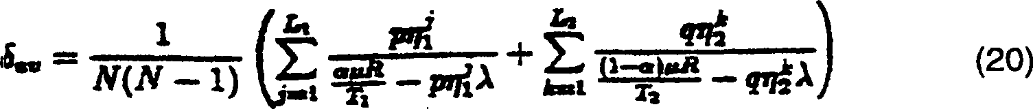
Der Einfachheit wegen benutzen wir ein M/M/1-Warteschlangenmodell, um das Verhalten eines einzelnen Teilnetzes zu beschreiben. Daher ist die Durchschnittsverzögerung eines Paketes, das das Teilnetz k durchläuft, gegeben durch δk = 1/(μCk – ηkλ), wobei 1/μ die Durchschnittspaketlänge in Bits ist; Ck ist die Kapazität des Teilnetzes in Bits/sec; und ηk ist die Belastung des Teilnetzes. Wenn ein genaueres Modell für das Verhalten des Teilnetzes benutzt wird, so führt dies nur zu einem unterschiedlichen Ausdruck für δk. Unter Benutzung der Little'schen Formel ist die Durchschnitts-Warteschlangenverzögervng durch das Netz gegeben durchFor simplicity, we use an M / M / 1 queuing model to describe the behavior of a single subnetwork. Therefore, the average delay of a packet passing through the subnetwork k is given by δ k = 1 / (μC k -η k λ), where 1 / μ is the average packet length in bits; C k is the capacity of the subnet in bits / sec; and η k is the load of the subnet. Using a more accurate model for the behavior of the subnet will only result in a different expression for δ k . Using Little's formula, the average queuing delay through the network is given by
![]()
![]()
Dabei
ist S bzw. Δ die
Gesamtzahl von Teilnetzen bzw. der offerierte Verkehr im Netz. Es
muss festgestellt werden, dass S = p + q und Δ = N(N – 1)λ. Da wir einen einzigen Transceiver
pro Knoten annehmen, soll α der
Teil des Zeitrahmens sein, den der Transceiver seinem physikalischen
Teilnetz während
der Phase I reserviert. Außerdem
soll angenommen werden, dass es M-Frequenbänder gibt und dass mit R die
Stoßgeschwindigkeit
des Senders in Bits/sec bezeichnet wird. Die Kapazität des physikalischen
Teilnetzes k ist gegeben durch ![]()
![]()
Dabei ist τq = max (q/M, 1). Es ist festzustellen, dass q-Frequenzbänder erforderlich sind, um die virtuellen Teilnetze gleichzeitig zu betreiben, da sie einander überlappen. Unter Benutzung der obigen Gleichung (7) ist die Durchschnitts-Warteschlangenverzögerung über dem Netz gegeben durchWhere τ q = max (q / M, 1). It should be noted that q frequency bands are required to operate the virtual subnets simultaneously because they overlap each other. Using equation (7) above, the average queue delay over the network is given by

Das heißt, die Last kann nicht die Kapazität des Teilnetzes überschreiten. Der maximale Wert von λ wird für αopt erreicht, der die folgende Formel befriedigtThat is, the load can not exceed the capacity of the subnet. The maximum value of λ is achieved for α opt , which satisfies the following formula
![]()
![]()
Die Auflösung der Gleichung (11) für α führt zuThe resolution the equation (11) for α leads to
![]()
![]()
Indem der Wert von αopt in einer der beiden Seiten der Gleichung (11) ersetzt wird, ergibt sichBy replacing the value of α opt in one of the two sides of equation (11), we obtain
![]()
![]()
Indem die Gleichungen (12) und (13) in der Gleichung (9) benutzt werden und nach einer gewissen Umsetzung, erhält man die GleichungBy doing equations (12) and (13) are used in equation (9) and after a certain implementation, you get the equation
![]()
![]()
Der
(bezüglich
der Stoßgeschwindigkeit)
normalisierte Benutzerdurchgang ist gegeben durch ![]()
![]()
Indem die Gleichungen (13) und (15) in Gleichung (16) eingegeben werden, ergibt sichBy doing equations (13) and (15) are entered into equation (16), surrendered
![]()
![]()
Unter
Benutzung der Gleichungen (15) und (16) wird die Gleichung (14)
wie folgt ![]()
![]()
Es
ist ferner festzustellen, dass bei 1 ≤ M ≤ min (r, q) der Durchsatz linear
mit der Zahl der Frequenbänder
M ist, d. h. durch Hinzufügen
weiterer Frequenbänder
steigt der Durchsatz linear an. Eine Erhöhung von M über min (r, q) erhöht weiter
den Durchsatz in einer unterlinearen Beziehung, bis ein Maximum
für M = max
(r, q) erreicht ist. ![]()
![]()
Um die Fehlertoleranz der vorliegenden Architektur zu berechnen, benutzen wir zwei Maßeinheiten, nämlich „Knoten-Verbindungsfähigkeit" und „Link-Verbindungsfähigkeit". Die Knoten-Verbindungsfähigkeit wird mit κ als Minimumanzahl von fehlerhaften Knoten definiert, die ein abgeschaltetes Netz erzeugen. Da jeder Knoten in der logischen Topologie direkt mit p + q – 2 anderen Knoten verbunden ist, beträgt die Knoten-Verbindungsfähigkeit des Netzwerks κ = p + q – 2. Wenn man beispielsweise ein 1024-Knotennetz mit 32 Teilnetzen und je 32 Knoten betrachtet, dann kann jeder 61. Knoten fehlerhaft sein, bevor das Netz abgeschaltet wird.Around to calculate the fault tolerance of the present architecture we have two units of measure, namely "node connectivity" and "link connectivity". The node connectivity becomes with κ as Minimum number of faulty nodes defined, which is a disconnected Generate network. Because each node in the logical topology directly with p + q - 2 is connected to other nodes, the node connectivity is of the network κ = p + q - 2. For example, if you have a 1024 node network with 32 subnetworks and each 32 nodes considered, then every 61st node can be faulty, before the power is turned off.
Die
Netz-Link-Verbindungsfähigkeit
wird mit – σ als minimale
Zahl von unverbundenen Knotenpfaden zwischen jedem Quell-Ziel-Paar
bezeichnet (d. h. Pfaden, die keine Links mehrfach benutzen oder
durch den gleichen Knoten verlaufen). Die Link-Verbindungsfähigkeit
der Topologie beträgt σ = 2 für Pfadlängen von
nicht mehr als zwei Sprüngen.
Wenn wir Pfadlängen
bis zu drei Sprüngen
zulassen (unter Benutzung einer Langpfadroute, vergleiche
E.2 MehrsprungnetzeE.2 multiple jump networks
Im Allgemeinen sind die Teilnetze nicht voll verbunden, und es können zahlreiche Sprünge innerhalb eines jeden physikalischen oder virtuellen Teilnetzes erforderlich sein. Wir nehmen an, dass in jedem Teilnetz eine Link-Aktivierung TDMA/FDMA (Multifrequenzkanäle pro Teilnetz sind möglich) benutzt wird, wenn jede Übertragungsstrecke wenigstens einmal während jedes Zeitrahmens aktiviert wird. Die folgende Analyse gilt für jedes Routenverfahren innerhalb des Mehrsprung-Teilnetzes.in the In general, the subnets are not fully connected, and many can jumps within each physical or virtual subnet to be required. We assume that each subnet has a link activation TDMA / FDMA (multi-frequency channels per subnet are possible) is used when every transmission link at least once during every time frame is activated. The following analysis applies to each Route method within the multiple hop subnet.
Durchsatzthroughput
In
der folgenden Analyse werden diese zusätzlichen Darstellungen benutzt:
T – Zahl der
Zeitschlitze, die in einem großen
Mehrsprungnetz benutzt werden.
T1 – Zahl der
Zeitschlitze, die in der Phase I benutzt werden.
T2 – Zahl der
Zeitschlitze, die in der Phase II benutzt werden.
L – Gesamtzahl
von Verbindungen, die in einem großen Mehrsprungnetz aktiviert
werden.
L1 – Gesamtzahl von Verbindungen,
die in den physikalischen Teilnetzen während der Phase I aktiviert
werden.
L2 – Gesamtzahl von Verbindungen,
die in den virtuellen Teilnetzen während der Phase II aktiviert
werden.
ηi – Belastung
der Verbindung i in einem großen
Mehrsprungnetz, d. h. die Zahl der Zeitabschnitte, in denen die
Verbindung i durch alle möglichen
N(N – 1)-Pfade
im Netz überquert
werden.
ηJ 1 – Belastung
der Verbindung j in dem physikalischen Teilnetz, d. h. die Zahl
der Zeiten, in denen die Verbindung j durch alle möglichen
q(q – 1)-Pfade
im physikalischen Teilnetz überquert
wird.
ηk 2 – Belastung
der Verbindung k in dem virtuellen Teilnetz, d. h. die Zahl der
Zeiten, in denen die Verbindung k durch alle möglichen p(p – 1)-Pfade
im virtuellen Teilnetz überquert
wird.
η – maximale
Verbindungsbelastung in einem großen Mehrsprungnetz (d. h. maxi(η')).
η1 – maximale
Verbindungsbelastung während
der Phase I (d. h. maxj(ηj 1)).
η2 – maximale
Verbindungsbelastung während
der Phase II (d. h. maxk(ηk 2)).The following analysis uses these additional representations:
T - number of timeslots used in a large multi-hop network.
T 1 - number of time slots used in phase I.
T 2 - number of time slots used in phase II.
L - Total number of connections activated in a large multi-hop network.
L 1 - Total number of connections that are activated in the physical subnets during Phase I.
L 2 - Total number of connections activated in the virtual subnets during Phase II.
η i - loading of the connection i in a large multi-hop network, ie the number of time periods in which the connection i are traversed by all possible N (N-1) paths in the network.
η J 1 - load the connection j in the physical subnet, ie the number of times that the connection j is crossed by all possible q (q - 1) paths in the physical subnet.
η k 2 - load the connection k in the virtual subnet, ie the number of times in which the connection k is traversed by all possible p (p - 1) paths in the virtual subnet.
η - maximum connection load in a large multi-hop network (ie max i (η ')).
η 1 - maximum connection load during phase I (ie max j (η j 1 )).
η 2 - maximum connection load during phase II (ie max k (η k 2 )).
Es soll wiederum ein homogener Verkehr angenommen werden und ein M/M//1-Warteschlangenmodell, um das Verhalten einer jeden aktivierten Verbindung zu beschreiben. Unter Benutzung der Little'schen Formel und unter Summierung sämtlicher aktivierter Verbindungen im Netz ist die durchschnittliche Warteschlangenverzögerung über dem Netz gegeben durchIt again, homogeneous traffic should be assumed and an M / M // 1 queuing model, to describe the behavior of each activated connection. Using Little's formula and summing up all enabled connections in the network is the average queue delay above that Net given by
Die Kapazität der Verbindungen ist invers proportional zur Zahl der Zeitschlitze (in der entsprechenden Phase), die von der Zahl der benutzten Frequenzkanäle abhängt. Der maximale Verkehr zwischen irgendwelchen zwei Knoten während der Phase I beträgt λ1 = αμR/(T1η1p). In gleicher Weise ist der maximale Verkehr zwischen irgendwelchen zwei Knoten während der Phase II gegeben durch λ2 = (1 – α)μR/(T2η2q). Um den optimalen Wert von α zu ermitteln, lösen wir λ1 = λ2 auf und finden, dassThe capacity of the connections is inversely proportional to the number of time slots (in the corresponding phase), which depends on the number of frequency channels used. The maximum traffic between any two nodes during phase I is λ 1 = αμR / (T 1 η 1 p). Similarly, the maximum traffic between any two nodes during phase II is given by λ 2 = (1-α) μR / (T 2 η 2 q). To find the optimal value of α, we solve for λ 1 = λ 2 and find that
![]()
![]()
Daher beträgt der maximale Verkehr zwischen irgendwelchen zwei Knoten im Netz gleichTherefore is the maximum traffic between any two nodes in the network equal
![]()
![]()
Der bezüglich der Stoßgeschwindigkeit normalisierte Netzdurchsatz ist gegeben durchOf the in terms of the impact speed normalized network throughput is given by
![]()
![]()
Es ist zu bemerken, dass η1 und η2 von der logischen Topologie und der Routenprozedur abhängen, die innerhalb der Teilnetze benutzt wird.It should be noted that η 1 and η 2 depend on the logical topology and route procedure used within the subnetworks.
Die Gleichung (17) kann als Spezialfall (Zweisprungnetz) aus der Gleichung (23) abgeleitet werden, indem ersetzt wird T1 = q(q – 1)τr, T2 = p(p – 1)τq und η1 = n2 = 1. Es ist festzustellen, dass q(q – 1) und p(p – 1) die Zahl von Verbindungen in voll verbundenen physikalischen und virtuellen Einsprung-Teilnetzen ist, die in einem reinen TDMA-Modus betrieben werden.The equation (17) can be derived as a special case (two-way network) from the equation (23) by replacing T 1 = q (q-1) τ r , T 2 = p (p-1) τ q and η 1 = n 2 = 1. It should be noted that q (q-1) and p (p-1) are the number of connections in fully connected physical and virtual entry subnetworks operating in a pure TDMA mode.
Das Verhalten (z. B. der Durchsatz) der vorliegenden Architektur und jenes eines einzigen großen Mehrsprung-Funknetzes werden nunmehr verglichen. Zuerst wird der Durchsatz für ein großes Mehrsprungnetz berechnet. Die Warteschlangenverzögerung über einem großen Mehrsprungnetz ist gegeben durchThe Behavior (eg, throughput) of the present architecture and that of a single large multi-hop radio network will now be compared. First, the throughput for a large multi-hop network calculated. The queue delay over a large multiple hop network is given by
![]()
![]()
Demgemäß ist der Durchsatz bei einem großen Mehrsprungnetz gegeben durchAccordingly, the Throughput at a large Given by multiple jump network
![]()
![]()
Die Durchsatzwerte für die vorliegende Architektur (Gleichung (23)) und für ein großes Mehrsprungnetz (Gleichung (25)) hängen von der Stärke der physikalischen und logischen Topologien ab, von der Routenprozedur und von der Zahl der Frequenzen. Es wurde beobachtet, dass speziell in großen Netzen mit einer zufälligen Topologie (einer Charakteristik von ad-hoc sporadischen Netzen) die maximale Verbindungsverkehrslast in einem großen Netzwerk beträchtlich höher ist als die maximale Verbindungsverkehrslast in den Teilnetzen, d. h. η >> pη1, qη2. Deshalb kann eine Aufteilung des Netzes die Überlastung vermindern und das Verhalten des Netzes verbessern, und zwar mit höherem Durchsatz und geringerer Verzögerung.The throughput values for the present architecture (Equation (23)) and for a large multiple hop network (Equation (25)) depend on the strength of the physical and logical topologies, the route procedure, and the number of frequencies. It has been observed that especially in large networks with a random topology (a characteristic of ad hoc sporadic networks) the maximum link traffic load in a large network is considerably higher than the maximum link load in the subnets, ie η >> pη 1 , qη 2 , Therefore, splitting the network can reduce congestion and improve network performance with higher throughput and less delay.
Es ist festzustellen, dass ein Nachteil großen Übertragungsradien zuzuordnen ist, die in verminderten Verbindungskapazitäten resultieren, weil zahlreichere Zeitschlitze benötigt werden. Weil die Verbindungsbelastung jedoch beträchtlich vermindert werden kann, so kann die Gesamtwirkung jedoch in einem erhöhten Durchsatz resultieren. Weil außerdem ein großes Mehrsprungnetz nicht den Vorteil von vielen Frequenzen (wenn verfügbar) in Anspruch nehmen kann, weil eine räumliche Wiederbenutzung besteht, so kann die vorliegende Architektur Mehrfachfrequenzen benutzen, um überlagerte virtuelle Teilnetze zu trennen. Dies ergibt ebenfalls einen erhöhten Durchsatz.It It should be noted that a disadvantage can be attributed to large transmission radii which results in decreased interconnection capacities because more numerous Time slots needed become. Because the connection load, however, considerable However, the overall effect can be reduced in one increased throughput result. Because as well a big Multiple Jump Network does not take advantage of many frequencies (if available) in Claim, because there is a spatial reuse, so the present architecture can use multiple frequencies, superimposed over separate virtual subnets. This also results in an increased throughput.
Das
folgende 16-Knotennetz-Beispiel veranschaulicht die Stärke der
vorgeschlagenen Architektur.
Durch Benutzung der kürzesten Route und einer TDMA/FDMA-Verbindungsaktivierungs-Zuordnung, wie beispielsweise in der nachfolgenden Anlage A beschrieben, können die Werte, die benötigt werden, um den Durchsatz gemäß der Zahl der verfügbaren Frequenzen zu berechnen, wie in Tabelle 1 gezeigt, bestimmt werden.By Use of the shortest Route and a TDMA / FDMA connection activation assignment, such as For example, in the following Appendix A, the Values that needed to set the throughput according to the number the available To calculate frequencies as shown in Table 1.
TABELLE
1 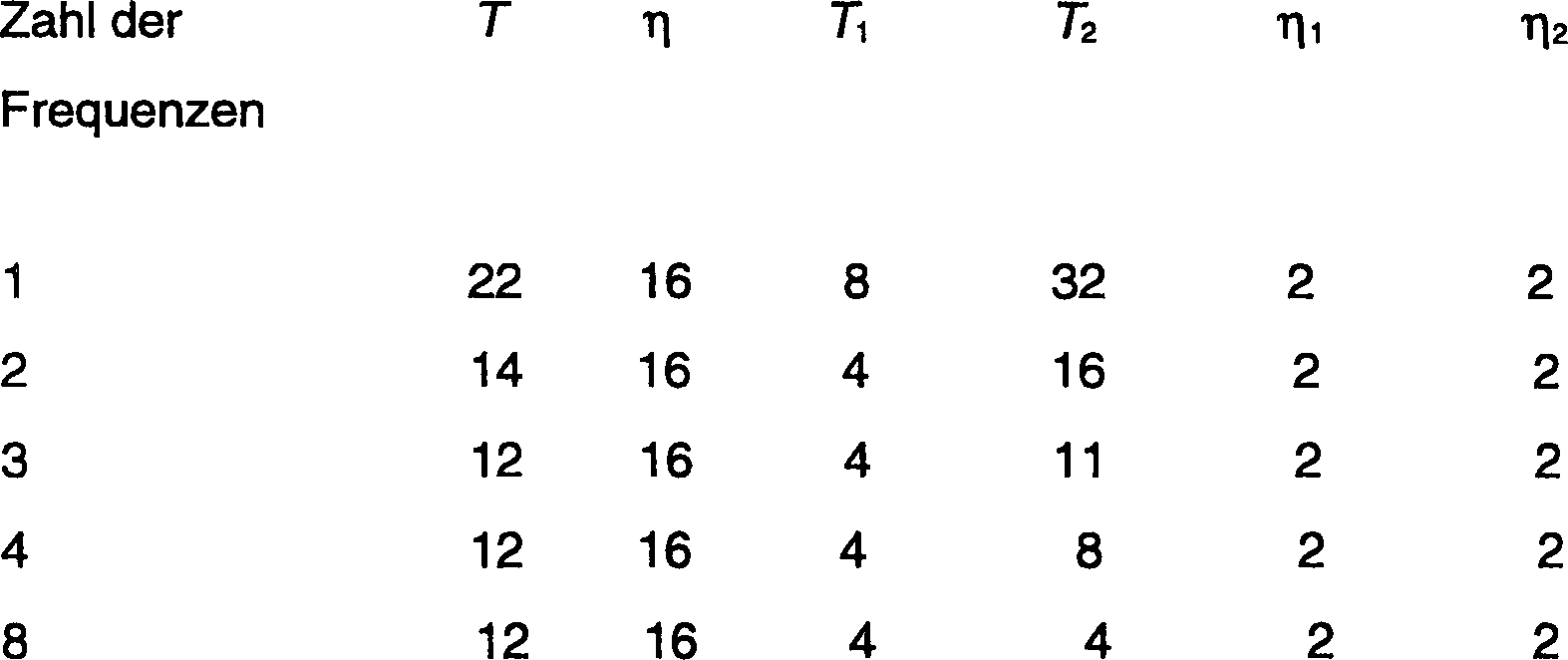
Der
Durchsatz für
ein großes
Mehrsprungnetz und für
ein Netz, welches vier virtuelle Teilnetze benutzt, ist in
Mit der erfindungsgemäßen Netzarchitektur ist es jedoch möglich, den Durchsatz weiter dadurch zu erhöhen, dass mehr (bis zu acht) Frequenzen hinzugefügt werden. Es ist zu beobachten, dass die durchschnittliche und die maximale Verbindungsbelastung in einem großen Mehrsprungnetz 8.33 bzw. 16 beträgt, während bei einem Netz, welches vier virtuelle Teilnetze gemäß der Erfindung benutzt, die entsprechenden Werte identisch – 8.0 sind, d. h. das Netz besitzt eine ausgeglichene Belastung. Die durchschnittliche und die maximale Zahl von Sprüngen in dem einen großen Netz betragen 2.29 bzw. 6.0, während bei einem Netz, das vier virtuelle Teilnetze benutzt, die entsprechenden Werte 2.13 und 4.0 betragen.With the network architecture according to the invention however, it is possible to further increase throughput by having more (up to eight) Added frequencies become. It is observed that the average and the maximum connection load in a large multiple hop network 8.33 or 16 while at a network using four virtual subnets according to the invention, the identical values - 8.0 are, d. H. the network has a balanced load. The average and the maximum number of jumps in the one big one Net are 2.29 and 6.0, respectively for a network that uses four virtual subnets, the corresponding one Values 2.13 and 4.0 are.
Zusammenfassend weist die vorliegende Architektur eine logische Topologie von physikalischen und virtuellen Teilnetzen auf und außerdem eine entsprechende Adressierung, ein Mobilitätsmanagement und Routenschemen. Die Architektur ist speziell anwendbar für mobile Funknetze und ist dynamischen Topologieänderungen infolge einer relativen Bewegung der Netzwerkknoten angepasst. Die Architektur teilt ein mobiles Funknetz in logisch unabhängige Teilnetze. Die Netzknoten sind Teile von physikalischen und virtuellen Teilnetzen und können ihre Zugehörigkeit zu diesen Teilnetzen infolge ihrer Mobilität ändern. Jedem Knoten ist eine Adresse, basierend auf einer gegenwärtigen Teilnetzangliederung, zugeordnet. Speziell in großen Netzen mit zufälliger Topologie wurde beobachtet, dass die Aufteilung des Netzes zu einer beträchtlich besser aufgeteilten Belastung führen kann als dies in einem großen Mehrsprungnetz der Fall ist, d. h. eine Maßnahme, die die Leistung des Netzes beträchtlich verbessern kann. Die Architektur ist in höchstem Maße fehlertolerant und kann eine relativ einfache Ortsaktualisierung und ein Nachführsystem benutzen. Infolge seiner Lastausgeglichenheit ergibt die Architektur im typischen Fall ein Netz mit relativ hohem Durchsatz und einer geringen Verzögerung.In summary For example, the present architecture has a logical topology of physical and virtual subnets and also a corresponding addressing, a mobility management and route schemes. The architecture is especially applicable for mobile Wireless networks and is dynamic topology changes as a result of a relative Adjusted movement of network nodes. The architecture divides mobile radio network in logically independent subnets. The network nodes are parts of physical and virtual subnets and can be theirs membership to change these subnets as a result of their mobility. Each node is one Address, based on a current subnet rollout, assigned. Especially in big ones Networks with random Topology has been observed that the division of the network into one considerably lead to a better split load than this can be a big one Multiple Jump Network is the case, d. H. a measure that affects the performance of the Network considerably can improve. The architecture is highly error tolerant and can a relatively simple location update and tracking system to use. As a result of its load balance, the architecture yields typically a relatively high throughput network and one low delay.
Anlage A – Ein verteiltes VerbindungsaktivierungsschemaAnnex A - A Distributed Link activation scheme
Im
Folgenden ist ein verteiltes on-line-TDMA/FDMA-Verbindungsaktivierungsschema zur Zuordnung einer
direkten Verbindung zwischen zwei Knoten beschrieben (z. B. dem
Knoten i und dem Knoten j). Es wird angenommen, dass die Knoten
i und j eine Kenntnis bestehender Zuordnungen zu ihren Nachbarknoten
haben (d. h. den Knoten innerhalb der „Hör"-Entfernung). Der Ausgang des Zuordnungsprozesses
ist eine Zuordnung der Verbindung i → j, d. h. ein zugeordnetes
Paar eines Zeitschlitzes und einer Frequenz – (t, f) oder eines Zeitschlitzes – t bei
nur einer Frequenz ist verfügbar
(reines TDMA). Die folgenden Darstellungen werden benutzt:
T – Satz verfügbarer Zeitschlitze.
F – Satz verfügbarer Frequenzen.
Tr – Satz
von Zeitschlitzen bei der Benutzung durch den Knoten r.
Fin r,h – Satz von
Frequenzen bei Benutzung von Verbindungseingängen nach Knoten, die dem Knoten
r benachbart sind während
des Zeitschlitzes th.
Fout r,h – Satz
von Frequenzen bei der Benutzung von Verbindungsausgängen von
Knoten, die dem Knoten r benachbart sind während des Zeitschlitzes th The following describes a distributed on-line TDMA / FDMA connection activation scheme for assigning a direct connection between two nodes (e.g., node i and node j). It is assumed that nodes i and j have a knowledge of existing allocations to their neighbor nodes (ie, the node within the "listen" distance.) The output of the allocation process is an association of the connection i → j, ie an associated pair of timeslot and one frequency - (t, f) or one time slot - t at only one frequency is available (pure TDMA) The following representations are used:
T - set of available timeslots.
F - set of available frequencies.
T r - set of time slots in use by node r.
F in r, h - set of frequencies using connection inputs to nodes adjacent to node r during time slot t h .
F out r, h - set of frequencies when using connection outputs of nodes assigned to node r are adjacent during the time slot t h
Die Gruppen T und F sind willkürlich am Auslass geordert.The Groups T and F are arbitrary ordered at the outlet.
KnotenzuordnungsschemaNode mapping scheme
-
1. Wähle
tk ∊ T – (Ti ⋃ Tj), wobei k die geringstwertige Zahl ist;
wenn kein Zeitschlitz verfügbar
ist, gehe zum Schritt
4 über;1. Choose t k ∈ T - (T i ⋃ T j ), where k is the least significant number; if no time slot is available, go to step4 above; -
2. Wähle
fl ∊ F – (Fin i,k ⋃ Fout j,k), wobei l
die geringstwertige Zahl ist, wenn keine Frequenz verfügbar ist,
T ← T – {tk} und gehe zum Schritt
1 über;2. Choose f l ∈ F - (F in i, k ⋃ F out j, k ), where l is the least significant number if no frequency is available, T ← T - {t k } and go to step1 above; - 3. Anhalten, das Paar (tk, fl) ist die i → j-Verbindungszuordnung;3. Stop, the pair (t k , f l ) is the i → j connection assignment;
- 4. Anhalten, die Verbindung i → j kann nicht zugeordnet werden.4. Stop, the connection i → j can not be assigned.
Es ist festzustellen, dass eine Zeitschlitzzuordnung nur logische Verbindungen erfordert, während eine Frequenzzuordnung sowohl logische als auch physikalische Verbindungen benötigt.It It should be noted that a time slot assignment only logical connections requires while a frequency allocation both logical and physical connections needed.
Die vorliegende Beschreibung repräsentiert ein bevorzugtes Ausführungsbeispiel der Erfindung. Es ist jedoch für den Fachmann klar, dass verschiedene Änderungen und Modifikationen getroffen werden können, ohne vom Rahmen der Erfindung abzuweichen, die durch die folgenden Ansprüche definiert ist.The present description represents a preferred embodiment the invention. It is, however, for It is clear to the person skilled in the art that various changes and modifications can be taken without to depart from the scope of the invention, which is defined by the following claims is.
Claims (27)
Applications Claiming Priority (3)
| Application Number | Priority Date | Filing Date | Title |
|---|---|---|---|
| US624730 | 1996-03-26 | ||
| US08/624,730 US5652751A (en) | 1996-03-26 | 1996-03-26 | Architecture for mobile radio networks with dynamically changing topology using virtual subnets |
| PCT/US1996/008009 WO1997036444A1 (en) | 1996-03-26 | 1996-05-30 | An architecture for mobile radio networks with dynamically changing topology using virtual subnets |
Publications (2)
| Publication Number | Publication Date |
|---|---|
| DE69633574D1 DE69633574D1 (en) | 2004-11-11 |
| DE69633574T2 true DE69633574T2 (en) | 2005-02-24 |
Family
ID=24503111
Family Applications (1)
| Application Number | Title | Priority Date | Filing Date |
|---|---|---|---|
| DE69633574T Expired - Lifetime DE69633574T2 (en) | 1996-03-26 | 1996-05-30 | ARCHITECTURE FOR MOBILE RADIO NETS WITH DYNAMIC TOPOLOGY ADAPTATION WITH THE HELP OF VIRTUAL COMPANIES |
Country Status (5)
| Country | Link |
|---|---|
| US (1) | US5652751A (en) |
| EP (1) | EP0886981B1 (en) |
| JP (1) | JP3810440B2 (en) |
| DE (1) | DE69633574T2 (en) |
| WO (1) | WO1997036444A1 (en) |
Families Citing this family (241)
| Publication number | Priority date | Publication date | Assignee | Title |
|---|---|---|---|---|
| NL9301544A (en) * | 1993-09-07 | 1995-04-03 | Nederland Ptt | Method for selecting connections in networks, and networks in which the method is applied. |
| US5854899A (en) * | 1996-05-09 | 1998-12-29 | Bay Networks, Inc. | Method and apparatus for managing virtual circuits and routing packets in a network/subnetwork environment |
| US6075777A (en) * | 1996-08-21 | 2000-06-13 | Lucent Technologies Inc. | Network flow framework for online dynamic channel allocation |
| US6581104B1 (en) * | 1996-10-01 | 2003-06-17 | International Business Machines Corporation | Load balancing in a distributed computer enterprise environment |
| GB9625020D0 (en) * | 1996-11-29 | 1997-01-15 | Northern Telecom Ltd | Network restoration |
| GB9720152D0 (en) * | 1996-12-18 | 1997-11-26 | Mayup Limited | Communications system and method |
| JP3097581B2 (en) * | 1996-12-27 | 2000-10-10 | 日本電気株式会社 | Ad-hoc local area network configuration method, communication method and terminal |
| DE19700303B4 (en) * | 1997-01-08 | 2005-11-03 | Deutsches Zentrum für Luft- und Raumfahrt e.V. | Radio transmission method for digital multimedia signals between subscriber stations in a local area network |
| US5949760A (en) * | 1997-03-21 | 1999-09-07 | Rockwell International Corporation | Simultaneous channel access transmission method for a multi-hop communications radio network |
| EP0976295B1 (en) * | 1997-04-18 | 2004-06-30 | Nortel Networks Limited | Connectionless communications network |
| US6011780A (en) * | 1997-05-23 | 2000-01-04 | Stevens Institute Of Technology | Transparant non-disruptable ATM network |
| US5991808A (en) * | 1997-06-02 | 1999-11-23 | Digital Equipment Corporation | Task processing optimization in a multiprocessor system |
| JP3180726B2 (en) * | 1997-08-05 | 2001-06-25 | 日本電気株式会社 | Mobile terminal control method |
| FI106509B (en) | 1997-09-26 | 2001-02-15 | Nokia Networks Oy | Legal interception in a telecommunications network |
| WO1999040694A1 (en) * | 1998-02-05 | 1999-08-12 | Mitsubishi International Gmbh | Method for establishing a radio communication and telecommunication network |
| US6147986A (en) * | 1998-03-06 | 2000-11-14 | Lucent Technologies Inc. | Address updating of wireless mobile terminal hosts affiliated with a wired network |
| AU3214899A (en) * | 1998-04-30 | 1999-11-23 | Motorola, Inc. | System and method for dynamically reconfiguring communication system performancethreshold data |
| US6400954B1 (en) * | 1998-05-15 | 2002-06-04 | Tlelefonaktiebolaget Lm Ericsson (Publ) | Methods and systems for mode selection based on access network capacity |
| US6167501A (en) * | 1998-06-05 | 2000-12-26 | Billions Of Operations Per Second, Inc. | Methods and apparatus for manarray PE-PE switch control |
| US6304556B1 (en) | 1998-08-24 | 2001-10-16 | Cornell Research Foundation, Inc. | Routing and mobility management protocols for ad-hoc networks |
| DE19848341A1 (en) * | 1998-10-21 | 2000-04-27 | Philips Corp Intellectual Pty | Automatic configuration of a bridge terminal for the transmission of data between several sub-networks in a local network |
| US6584102B1 (en) * | 1998-12-21 | 2003-06-24 | At&T Corp. | Communication network apparatus and method |
| EP1142227A2 (en) * | 1998-12-23 | 2001-10-10 | Nokia Wireless Routers, Inc. | A unified routing scheme for ad-hoc internetworking |
| US6104712A (en) * | 1999-02-22 | 2000-08-15 | Robert; Bruno G. | Wireless communication network including plural migratory access nodes |
| DE19918896A1 (en) | 1999-04-26 | 2000-11-02 | Mueschenborn Hans Joachim | Logical network system |
| US6331973B1 (en) * | 1999-04-30 | 2001-12-18 | Rockwell Collins, Inc. | Unifying slot assignment protocol multiple access system |
| US6504829B1 (en) * | 1999-06-28 | 2003-01-07 | Rockwell Collins, Inc. | Method and apparatus for managing communication resources using channelized neighborhoods |
| AU6063200A (en) * | 1999-06-30 | 2001-01-31 | Apcot Medical Systems, Inc. | Method and system for data communications and dynamic networking between vehicles |
| US6654614B2 (en) | 1999-07-06 | 2003-11-25 | Widcomm, Inc. | Implementation of power control in a wireless overlay network |
| US6891820B1 (en) | 1999-07-06 | 2005-05-10 | Broadcom Corporation | Utilization of the internet protocol to facilitate communication involving mobile devices |
| US6691173B2 (en) | 1999-07-06 | 2004-02-10 | Widcomm, Inc. | Distributed management of an extended network containing short-range wireless links |
| US6788702B1 (en) * | 1999-10-15 | 2004-09-07 | Nokia Wireless Routers, Inc. | Protocol for neighborhood-established transmission scheduling |
| US6836463B2 (en) * | 1999-10-15 | 2004-12-28 | Nokia Corporation | System for communicating labeled routing trees to establish preferred paths and source routes with local identifiers in wireless computer networks |
| US6711409B1 (en) * | 1999-12-15 | 2004-03-23 | Bbnt Solutions Llc | Node belonging to multiple clusters in an ad hoc wireless network |
| DE19961399C2 (en) * | 1999-12-20 | 2002-08-22 | Mueschenborn Hans Joachim | Protection of security-critical data in networks |
| US8019836B2 (en) | 2002-01-02 | 2011-09-13 | Mesh Comm, Llc | Wireless communication enabled meter and network |
| US6870816B1 (en) * | 2000-03-01 | 2005-03-22 | Motorola, Inc. | Self-organizing network with decision engine and method |
| US7042863B1 (en) | 2000-03-13 | 2006-05-09 | Broadcom Corporation | Efficient time-division multiplexed addressing protocol |
| US6816460B1 (en) * | 2000-03-14 | 2004-11-09 | Lucent Technologies Inc. | Location based routing for mobile ad-hoc networks |
| US7284266B1 (en) | 2000-03-21 | 2007-10-16 | Broadcom Corporation | System and method for secure biometric identification |
| US6643336B1 (en) | 2000-04-18 | 2003-11-04 | Widcomm, Inc. | DC offset and bit timing system and method for use with a wireless transceiver |
| US6791994B1 (en) | 2000-04-19 | 2004-09-14 | Rockwell Collins, Inc. | Method and apparatus for assigning receive slots in a dynamic assignment environment |
| US6873610B1 (en) * | 2000-05-01 | 2005-03-29 | Mobular Technologies, Inc. | System and method for efficiently accessing affiliated network addresses from a wireless device |
| WO2002003091A2 (en) * | 2000-07-03 | 2002-01-10 | Ecole Polytechnique Federale De Lausanne (Epfl) | Method and wireless terminal for generating and maintaining a relative positioning system |
| US6950657B1 (en) * | 2000-07-03 | 2005-09-27 | Lucent Technologies Inc. | Method for providing multiple points of connectivity to subscribers of wireless communication networks |
| US6885651B1 (en) | 2000-08-29 | 2005-04-26 | Rockwell Collins | Maintaining an adaptive broadcast channel using both transmitter directed and receiver directed broadcasts |
| US6810022B1 (en) | 2000-08-29 | 2004-10-26 | Rockwell Collins | Full duplex communication slot assignment |
| US6781967B1 (en) | 2000-08-29 | 2004-08-24 | Rockwell Collins, Inc. | Scheduling techniques for receiver directed broadcast applications |
| US6928061B1 (en) | 2000-09-06 | 2005-08-09 | Nokia, Inc. | Transmission-scheduling coordination among collocated internet radios |
| US6973053B1 (en) | 2000-09-12 | 2005-12-06 | Bbnt Solutions Llc | Using direct cluster member to cluster member links to improve performance in mobile communication systems |
| FR2814631B1 (en) * | 2000-09-26 | 2003-04-25 | Thomson Csf | METHOD FOR PRESERVING AND / OR RESTORING COMMUNICATION LINKS IN A PLANNED NETWORK WITH MOBILE COMPONENTS |
| GB2367970B (en) * | 2000-10-09 | 2004-01-21 | Ericsson Telefon Ab L M | Network topologies |
| US6807165B2 (en) * | 2000-11-08 | 2004-10-19 | Meshnetworks, Inc. | Time division protocol for an ad-hoc, peer-to-peer radio network having coordinating channel access to shared parallel data channels with separate reservation channel |
| US6873839B2 (en) | 2000-11-13 | 2005-03-29 | Meshnetworks, Inc. | Prioritized-routing for an ad-hoc, peer-to-peer, mobile radio access system |
| US7072650B2 (en) * | 2000-11-13 | 2006-07-04 | Meshnetworks, Inc. | Ad hoc peer-to-peer mobile radio access system interfaced to the PSTN and cellular networks |
| US7522568B2 (en) * | 2000-12-22 | 2009-04-21 | Terahop Networks, Inc. | Propagating ad hoc wireless networks based on common designation and routine |
| US7554442B2 (en) * | 2005-06-17 | 2009-06-30 | Terahop Networks, Inc. | Event-driven mobile hazmat monitoring |
| US20080303897A1 (en) * | 2000-12-22 | 2008-12-11 | Terahop Networks, Inc. | Visually capturing and monitoring contents and events of cargo container |
| US7529547B2 (en) * | 2005-06-03 | 2009-05-05 | Terahop Networks, Inc. | Using wake-up receivers for soft hand-off in wireless communications |
| US7539520B2 (en) * | 2005-06-17 | 2009-05-26 | Terahop Networks, Inc. | Remote sensor interface (RSI) having power conservative transceiver for transmitting and receiving wakeup signals |
| US7209771B2 (en) * | 2000-12-22 | 2007-04-24 | Terahop Networks, Inc. | Battery powered wireless transceiver having LPRF component and second wake up receiver |
| US7200132B2 (en) * | 2000-12-22 | 2007-04-03 | Terahop Networks, Inc. | Forming ad hoc RSI networks among transceivers sharing common designation |
| US7542849B2 (en) * | 2005-06-03 | 2009-06-02 | Terahop Networks, Inc. | Network aided terrestrial triangulation using stars (NATTS) |
| US7733818B2 (en) * | 2000-12-22 | 2010-06-08 | Terahop Networks, Inc. | Intelligent node communication using network formation messages in a mobile Ad hoc network |
| US7526381B2 (en) * | 2005-06-03 | 2009-04-28 | Terahop Networks, Inc. | Network aided terrestrial triangulation using stars (NATTS) |
| US7574168B2 (en) * | 2005-06-16 | 2009-08-11 | Terahop Networks, Inc. | Selective GPS denial system |
| US7783246B2 (en) * | 2005-06-16 | 2010-08-24 | Terahop Networks, Inc. | Tactical GPS denial and denial detection system |
| US6934540B2 (en) * | 2000-12-22 | 2005-08-23 | Seekernet, Inc. | Network formation in asset-tracking system based on asset class |
| US7583769B2 (en) * | 2005-06-16 | 2009-09-01 | Terahop Netowrks, Inc. | Operating GPS receivers in GPS-adverse environment |
| US7430437B2 (en) * | 2000-12-22 | 2008-09-30 | Terahop Networks, Inc. | Transmitting sensor-acquired data using step-power filtering |
| US7563991B2 (en) * | 2005-06-08 | 2009-07-21 | Terahop Networks, Inc. | All weather housing assembly for electronic components |
| US7705747B2 (en) * | 2005-08-18 | 2010-04-27 | Terahop Networks, Inc. | Sensor networks for monitoring pipelines and power lines |
| US6745027B2 (en) | 2000-12-22 | 2004-06-01 | Seekernet Incorporated | Class switched networks for tracking articles |
| US7830850B2 (en) * | 2000-12-22 | 2010-11-09 | Terahop Networks, Inc. | Class-switching in class-based data communcations network |
| US8280345B2 (en) * | 2000-12-22 | 2012-10-02 | Google Inc. | LPRF device wake up using wireless tag |
| US20100330930A1 (en) * | 2000-12-22 | 2010-12-30 | Twitchell Robert W | Lprf device wake up using wireless tag |
| US7940716B2 (en) | 2005-07-01 | 2011-05-10 | Terahop Networks, Inc. | Maintaining information facilitating deterministic network routing |
| US7209468B2 (en) * | 2000-12-22 | 2007-04-24 | Terahop Networks, Inc. | Forming communication cluster of wireless AD HOC network based on common designation |
| US8050625B2 (en) * | 2000-12-22 | 2011-11-01 | Terahop Networks, Inc. | Wireless reader tags (WRTs) with sensor components in asset monitoring and tracking systems |
| US7830273B2 (en) * | 2005-08-18 | 2010-11-09 | Terahop Networks, Inc. | Sensor networks for pipeline monitoring |
| US7391321B2 (en) * | 2005-01-10 | 2008-06-24 | Terahop Networks, Inc. | Keyhole communication device for tracking and monitoring shipping container and contents thereof |
| US7155264B2 (en) * | 2000-12-22 | 2006-12-26 | Terahop Networks, Inc. | Systems and methods having LPRF device wake up using wireless tag |
| US7133704B2 (en) * | 2000-12-22 | 2006-11-07 | Terahop Networks, Inc. | Manufacture of LPRF device wake up using wireless tag |
| US7221668B2 (en) * | 2000-12-22 | 2007-05-22 | Terahop Networks, Inc. | Communications within population of wireless transceivers based on common designation |
| US7574300B2 (en) * | 2005-06-16 | 2009-08-11 | Terahop Networks, Inc. | GPS denial device detection and location system |
| NL1017388C2 (en) * | 2001-02-16 | 2002-08-19 | Marc Van Oldenborgh | Organic data network with a dynamic topology. |
| US7151769B2 (en) * | 2001-03-22 | 2006-12-19 | Meshnetworks, Inc. | Prioritized-routing for an ad-hoc, peer-to-peer, mobile radio access system based on battery-power levels and type of service |
| US20020142721A1 (en) * | 2001-03-29 | 2002-10-03 | Motorola, Inc. | Method and device for selecting a wireless communication path |
| US20020145978A1 (en) * | 2001-04-05 | 2002-10-10 | Batsell Stephen G. | Mrp-based hybrid routing for mobile ad hoc networks |
| US7106820B2 (en) * | 2001-04-10 | 2006-09-12 | Broadcom Corporation | System and method for establishing word synchronization |
| US7269183B2 (en) | 2001-04-27 | 2007-09-11 | Broadcom Corporation | System and method for connecting bluetooth-enabled devices to a personal computer |
| DE10122042A1 (en) * | 2001-05-07 | 2002-11-14 | Philips Corp Intellectual Pty | Network with prioritized data forwarding between sub-networks |
| DE10127880A1 (en) * | 2001-06-11 | 2002-12-12 | Philips Corp Intellectual Pty | Dynamic network, especially ad hoc network, has routing information stored in local routing tables in nodes updated by exchanging update requests and responses between nodes |
| KR100930637B1 (en) * | 2001-06-14 | 2009-12-09 | 메시네트웍스, 인코포레이티드 | Embedded routing algorithms under the internet protocol routing layer of a software architecture protocol stack in a mobile ad-hoc network |
| JP2004537206A (en) * | 2001-06-30 | 2004-12-09 | ノキア インコーポレイテッド | Apparatus and method for delivering packets in a multi-hop wireless network |
| US7206294B2 (en) * | 2001-08-15 | 2007-04-17 | Meshnetworks, Inc. | Movable access points and repeaters for minimizing coverage and capacity constraints in a wireless communications network and a method for using the same |
| US7072323B2 (en) * | 2001-08-15 | 2006-07-04 | Meshnetworks, Inc. | System and method for performing soft handoff in a wireless data network |
| US7349380B2 (en) * | 2001-08-15 | 2008-03-25 | Meshnetworks, Inc. | System and method for providing an addressing and proxy scheme for facilitating mobility of wireless nodes between wired access points on a core network of a communications network |
| US7613458B2 (en) * | 2001-08-28 | 2009-11-03 | Meshnetworks, Inc. | System and method for enabling a radio node to selectably function as a router in a wireless communications network |
| US7145903B2 (en) * | 2001-09-06 | 2006-12-05 | Meshnetworks, Inc. | Multi-master bus architecture for system-on-chip designs |
| ATE361590T1 (en) * | 2001-09-25 | 2007-05-15 | Meshnetworks Inc | SSYSTGEM AND METHOD FOR USING ALGORITHMS AND PROTOCOLS TO OPTIMIZE CARRIER SENSE MULTIPLE ACCESS (CSMA) PROTOCOLS IN WIRELESS NETWORKS |
| US6754188B1 (en) | 2001-09-28 | 2004-06-22 | Meshnetworks, Inc. | System and method for enabling a node in an ad-hoc packet-switched wireless communications network to route packets based on packet content |
| US20030069976A1 (en) * | 2001-10-05 | 2003-04-10 | Adc Telecommunications, Inc. | Intelligent round robining |
| US6768730B1 (en) | 2001-10-11 | 2004-07-27 | Meshnetworks, Inc. | System and method for efficiently performing two-way ranging to determine the location of a wireless node in a communications network |
| US6937602B2 (en) * | 2001-10-23 | 2005-08-30 | Meshnetworks, Inc. | System and method for providing a congestion optimized address resolution protocol for wireless ad-hoc networks |
| US6771666B2 (en) | 2002-03-15 | 2004-08-03 | Meshnetworks, Inc. | System and method for trans-medium address resolution on an ad-hoc network with at least one highly disconnected medium having multiple access points to other media |
| US6982982B1 (en) | 2001-10-23 | 2006-01-03 | Meshnetworks, Inc. | System and method for providing a congestion optimized address resolution protocol for wireless ad-hoc networks |
| US7120456B1 (en) | 2001-11-07 | 2006-10-10 | Bbn Technologies Corp. | Wireless terminals with multiple transceivers |
| US7181214B1 (en) | 2001-11-13 | 2007-02-20 | Meshnetworks, Inc. | System and method for determining the measure of mobility of a subscriber device in an ad-hoc wireless network with fixed wireless routers and wide area network (WAN) access points |
| US7136587B1 (en) | 2001-11-15 | 2006-11-14 | Meshnetworks, Inc. | System and method for providing simulated hardware-in-the-loop testing of wireless communications networks |
| US6728545B1 (en) | 2001-11-16 | 2004-04-27 | Meshnetworks, Inc. | System and method for computing the location of a mobile terminal in a wireless communications network |
| US7221686B1 (en) | 2001-11-30 | 2007-05-22 | Meshnetworks, Inc. | System and method for computing the signal propagation time and the clock correction for mobile stations in a wireless network |
| WO2003051061A2 (en) * | 2001-12-11 | 2003-06-19 | Ip2H Ag | Method for establishing a communication connection and a telecommunication network |
| US7190672B1 (en) | 2001-12-19 | 2007-03-13 | Meshnetworks, Inc. | System and method for using destination-directed spreading codes in a multi-channel metropolitan area wireless communications network |
| US7180875B1 (en) | 2001-12-20 | 2007-02-20 | Meshnetworks, Inc. | System and method for performing macro-diversity selection and distribution of routes for routing data packets in Ad-Hoc networks |
| US7106707B1 (en) | 2001-12-20 | 2006-09-12 | Meshnetworks, Inc. | System and method for performing code and frequency channel selection for combined CDMA/FDMA spread spectrum communication systems |
| US7280545B1 (en) | 2001-12-20 | 2007-10-09 | Nagle Darragh J | Complex adaptive routing system and method for a nodal communication network |
| US7072618B1 (en) | 2001-12-21 | 2006-07-04 | Meshnetworks, Inc. | Adaptive threshold selection system and method for detection of a signal in the presence of interference |
| US7035539B2 (en) * | 2002-01-09 | 2006-04-25 | Fujitsu Limited | Interconnecting nodes in an optical communication system |
| US7117264B2 (en) * | 2002-01-10 | 2006-10-03 | International Business Machines Corporation | Method and system for peer to peer communication in a network environment |
| US6674790B1 (en) | 2002-01-24 | 2004-01-06 | Meshnetworks, Inc. | System and method employing concatenated spreading sequences to provide data modulated spread signals having increased data rates with extended multi-path delay spread |
| US6617990B1 (en) | 2002-03-06 | 2003-09-09 | Meshnetworks | Digital-to-analog converter using pseudo-random sequences and a method for using the same |
| US7058018B1 (en) | 2002-03-06 | 2006-06-06 | Meshnetworks, Inc. | System and method for using per-packet receive signal strength indication and transmit power levels to compute path loss for a link for use in layer II routing in a wireless communication network |
| CA2478905A1 (en) | 2002-03-15 | 2003-09-25 | Meshnetworks, Inc. | System and method for auto-configuration and discovery of ip to mac address mapping and gateway presence |
| US6904021B2 (en) | 2002-03-15 | 2005-06-07 | Meshnetworks, Inc. | System and method for providing adaptive control of transmit power and data rate in an ad-hoc communication network |
| US7433691B1 (en) * | 2002-03-25 | 2008-10-07 | Meshnetworks, Inc. | System and method for enabling an access point in an ad-hoc wireless network with fixed wireless routers and wide area network (WAN) access points to identify the location of subscriber device |
| US6987795B1 (en) | 2002-04-08 | 2006-01-17 | Meshnetworks, Inc. | System and method for selecting spreading codes based on multipath delay profile estimation for wireless transceivers in a communication network |
| US7200149B1 (en) | 2002-04-12 | 2007-04-03 | Meshnetworks, Inc. | System and method for identifying potential hidden node problems in multi-hop wireless ad-hoc networks for the purpose of avoiding such potentially problem nodes in route selection |
| US7107498B1 (en) | 2002-04-16 | 2006-09-12 | Methnetworks, Inc. | System and method for identifying and maintaining reliable infrastructure links using bit error rate data in an ad-hoc communication network |
| US6580981B1 (en) | 2002-04-16 | 2003-06-17 | Meshnetworks, Inc. | System and method for providing wireless telematics store and forward messaging for peer-to-peer and peer-to-peer-to-infrastructure a communication network |
| US7142524B2 (en) * | 2002-05-01 | 2006-11-28 | Meshnetworks, Inc. | System and method for using an ad-hoc routing algorithm based on activity detection in an ad-hoc network |
| US6970444B2 (en) | 2002-05-13 | 2005-11-29 | Meshnetworks, Inc. | System and method for self propagating information in ad-hoc peer-to-peer networks |
| US7016306B2 (en) * | 2002-05-16 | 2006-03-21 | Meshnetworks, Inc. | System and method for performing multiple network routing and provisioning in overlapping wireless deployments |
| US7284268B2 (en) | 2002-05-16 | 2007-10-16 | Meshnetworks, Inc. | System and method for a routing device to securely share network data with a host utilizing a hardware firewall |
| US7167715B2 (en) * | 2002-05-17 | 2007-01-23 | Meshnetworks, Inc. | System and method for determining relative positioning in AD-HOC networks |
| US7106703B1 (en) | 2002-05-28 | 2006-09-12 | Meshnetworks, Inc. | System and method for controlling pipeline delays by adjusting the power levels at which nodes in an ad-hoc network transmit data packets |
| US6687259B2 (en) | 2002-06-05 | 2004-02-03 | Meshnetworks, Inc. | ARQ MAC for ad-hoc communication networks and a method for using the same |
| US6744766B2 (en) | 2002-06-05 | 2004-06-01 | Meshnetworks, Inc. | Hybrid ARQ for a wireless Ad-Hoc network and a method for using the same |
| US7610027B2 (en) * | 2002-06-05 | 2009-10-27 | Meshnetworks, Inc. | Method and apparatus to maintain specification absorption rate at a wireless node |
| US7054126B2 (en) * | 2002-06-05 | 2006-05-30 | Meshnetworks, Inc. | System and method for improving the accuracy of time of arrival measurements in a wireless ad-hoc communications network |
| WO2003105353A2 (en) * | 2002-06-11 | 2003-12-18 | Meshnetworks, Inc. | System and method for multicast media access using broadcast transmissions with multiple acknowledgments in an ad-hoc communications network |
| US7215638B1 (en) | 2002-06-19 | 2007-05-08 | Meshnetworks, Inc. | System and method to provide 911 access in voice over internet protocol systems without compromising network security |
| US7072432B2 (en) * | 2002-07-05 | 2006-07-04 | Meshnetworks, Inc. | System and method for correcting the clock drift and maintaining the synchronization of low quality clocks in wireless networks |
| US7796570B1 (en) | 2002-07-12 | 2010-09-14 | Meshnetworks, Inc. | Method for sparse table accounting and dissemination from a mobile subscriber device in a wireless mobile ad-hoc network |
| US7046962B1 (en) | 2002-07-18 | 2006-05-16 | Meshnetworks, Inc. | System and method for improving the quality of range measurement based upon historical data |
| US7042867B2 (en) * | 2002-07-29 | 2006-05-09 | Meshnetworks, Inc. | System and method for determining physical location of a node in a wireless network during an authentication check of the node |
| US7707307B2 (en) * | 2003-01-09 | 2010-04-27 | Cisco Technology, Inc. | Method and apparatus for constructing a backup route in a data communications network |
| ATE515856T1 (en) * | 2003-01-13 | 2011-07-15 | Meshnetworks Inc | SYSTEM AND METHOD FOR ACHIEVEING CONTINUOUS CONNECTIVITY WITH AN ACCESS POINT OR GATEWAY IN A WIRELESS NETWORK |
| US7076259B2 (en) * | 2003-03-13 | 2006-07-11 | Meshnetworks, Inc. | Real-time system and method for improving the accuracy of the computed location of mobile subscribers in a wireless ad-hoc network using a low speed central processing unit |
| US7171220B2 (en) * | 2003-03-14 | 2007-01-30 | Meshnetworks, Inc. | System and method for analyzing the precision of geo-location services in a wireless network terminal |
| US7526540B2 (en) * | 2003-04-22 | 2009-04-28 | International Business Machines Corporation | System and method for assigning data collection agents to storage area network nodes in a storage area network resource management system |
| US7277394B2 (en) * | 2003-05-12 | 2007-10-02 | Motorola, Inc. | Non interfering group based wireless network protocols |
| JP2006526938A (en) * | 2003-06-05 | 2006-11-24 | メッシュネットワークス インコーポレイテッド | System and method for determining synchronization points in an OFDM modem for accurate time of flight measurements |
| WO2004114690A1 (en) * | 2003-06-05 | 2004-12-29 | Meshnetworks, Inc. | Optimal routing in ad hac wireless communication network |
| WO2004109476A2 (en) * | 2003-06-05 | 2004-12-16 | Meshnetworks, Inc. | System and method to maximize channel utilization in a multi-channel wireless communication network |
| WO2004110082A1 (en) * | 2003-06-05 | 2004-12-16 | Meshnetworks, Inc. | System and method for determining location of a device in a wireless communication network |
| JP5054377B2 (en) | 2003-06-06 | 2012-10-24 | メッシュネットワークス インコーポレイテッド | Systems and methods for achieving fairness and service differentiation in ad hoc networks |
| KR20060018882A (en) * | 2003-06-06 | 2006-03-02 | 메시네트웍스, 인코포레이티드 | A method to provide a measure of link reliability to a routing protocol in an ad hoc wireless network |
| US7061925B2 (en) * | 2003-06-06 | 2006-06-13 | Meshnetworks, Inc. | System and method for decreasing latency in locating routes between nodes in a wireless communication network |
| US7126951B2 (en) * | 2003-06-06 | 2006-10-24 | Meshnetworks, Inc. | System and method for identifying the floor number where a firefighter in need of help is located using received signal strength indicator and signal propagation time |
| US7580360B2 (en) * | 2003-10-14 | 2009-08-25 | Cisco Technology, Inc. | Method and apparatus for generating routing information in a data communications network |
| US7385999B1 (en) | 2003-10-20 | 2008-06-10 | Rockwell Collins, Inc. | Heuristics for combining inter-channel and intra-channel communications in a wireless communications environment |
| US7403780B2 (en) | 2004-02-19 | 2008-07-22 | Rockwell Collins, Inc. | Hybrid open/closed loop filtering for link quality estimation |
| US7826372B1 (en) | 2004-03-26 | 2010-11-02 | Rockwell Collins, Inc. | Network routing process for regulating traffic through advantaged and disadvantaged nodes |
| US7382799B1 (en) | 2004-05-18 | 2008-06-03 | Rockwell Collins, Inc. | On-demand broadcast protocol |
| US7142107B2 (en) | 2004-05-27 | 2006-11-28 | Lawrence Kates | Wireless sensor unit |
| US7310380B1 (en) | 2004-05-28 | 2007-12-18 | Rockwell Collins, Inc. | Generic transmission parameter configuration |
| US7397810B1 (en) | 2004-06-14 | 2008-07-08 | Rockwell Collins, Inc. | Artery nodes |
| US7577106B1 (en) | 2004-07-12 | 2009-08-18 | Cisco Technology, Inc. | Method and apparatus for managing a transition for a class of data between first and second topologies in a data communications network |
| US7167463B2 (en) * | 2004-10-07 | 2007-01-23 | Meshnetworks, Inc. | System and method for creating a spectrum agile wireless multi-hopping network |
| US7496644B2 (en) * | 2004-11-05 | 2009-02-24 | Cisco Technology, Inc. | Method and apparatus for managing a network component change |
| EP1839286A2 (en) * | 2005-01-10 | 2007-10-03 | Terahop Networks, Inc. | Keyhole communication device for tracking and monitoring shipping container and contents thereof |
| US20060159024A1 (en) * | 2005-01-18 | 2006-07-20 | Hester Lance E | Method and apparatus for responding to node anormalities within an ad-hoc network |
| US7894807B1 (en) * | 2005-03-30 | 2011-02-22 | Openwave Systems Inc. | System and method for routing a wireless connection in a hybrid network |
| US7606171B1 (en) | 2005-07-28 | 2009-10-20 | Rockwell Collins, Inc. | Skeletal node rules for connected dominating set in ad-hoc networks |
| US7828342B2 (en) * | 2005-07-29 | 2010-11-09 | Terahop Networks, Inc. | Reusable locking body, of bolt-type seal lock, having open-ended passageway and U-shaped bolt |
| US20070032245A1 (en) * | 2005-08-05 | 2007-02-08 | Alapuranen Pertti O | Intelligent transportation system and method |
| CA2559182C (en) | 2005-09-12 | 2017-05-09 | Acuity Brands, Inc. | Network operation center for a light management system having networked intelligent luminaire managers |
| CA2624502C (en) | 2005-10-05 | 2013-07-09 | Guardian Networks, Llc | A method and system for remotely monitoring and controlling field devices with a street lamp elevated mesh network |
| WO2007067831A1 (en) * | 2005-10-31 | 2007-06-14 | Terahop Networks, Inc. | Determining relative elevation using gps and ranging |
| IL179135A (en) * | 2005-11-10 | 2010-11-30 | Elbit Systems Electro Optics Elop Ltd | Head up display mechanism |
| US8694435B1 (en) * | 2005-11-14 | 2014-04-08 | American Express Travel Related Services Company, Inc. | System and method for linking point of sale devices within a virtual network |
| IL172915A (en) | 2005-12-29 | 2012-03-29 | Elbit Systems Ltd | Geographical communication networking system and method |
| US20090129306A1 (en) | 2007-02-21 | 2009-05-21 | Terahop Networks, Inc. | Wake-up broadcast including network information in common designation ad hoc wireless networking |
| EP1972159A1 (en) * | 2006-01-01 | 2008-09-24 | Terahop Networks, Inc. | Determining presence of radio frequency communication device |
| US7656851B1 (en) * | 2006-10-12 | 2010-02-02 | Bae Systems Information And Electronic Systems Integration Inc. | Adaptive message routing for mobile ad HOC networks |
| US8045481B2 (en) * | 2006-10-20 | 2011-10-25 | Ciena Corporation | System and method for supporting virtualized links at an exterior network-to-network interface |
| US8295295B2 (en) * | 2007-01-24 | 2012-10-23 | Cooper Technologies Company | System and method for automatically segmenting and merging routing domains within networks |
| US8223680B2 (en) * | 2007-02-21 | 2012-07-17 | Google Inc. | Mesh network control using common designation wake-up |
| US8140276B2 (en) * | 2008-02-27 | 2012-03-20 | Abl Ip Holding Llc | System and method for streetlight monitoring diagnostics |
| US8462662B2 (en) * | 2008-05-16 | 2013-06-11 | Google Inc. | Updating node presence based on communication pathway |
| WO2009151877A2 (en) | 2008-05-16 | 2009-12-17 | Terahop Networks, Inc. | Systems and apparatus for securing a container |
| US8204028B2 (en) * | 2008-06-12 | 2012-06-19 | Intel Corporation | Techniques for spatial reuse in wireless personal area networks based on virtual time divisional multiple access |
| US8391435B2 (en) | 2008-12-25 | 2013-03-05 | Google Inc. | Receiver state estimation in a duty cycled radio |
| US8300551B2 (en) * | 2009-01-28 | 2012-10-30 | Google Inc. | Ascertaining presence in wireless networks |
| US8705523B2 (en) | 2009-02-05 | 2014-04-22 | Google Inc. | Conjoined class-based networking |
| US20150237400A1 (en) * | 2013-01-05 | 2015-08-20 | Benedict Ow | Secured file distribution system and method |
| US9112790B2 (en) | 2013-06-25 | 2015-08-18 | Google Inc. | Fabric network |
| US10454714B2 (en) | 2013-07-10 | 2019-10-22 | Nicira, Inc. | Method and system of overlay flow control |
| US10749711B2 (en) | 2013-07-10 | 2020-08-18 | Nicira, Inc. | Network-link method useful for a last-mile connectivity in an edge-gateway multipath system |
| CA2908835C (en) | 2014-10-15 | 2017-04-04 | Abl Ip Holding Llc | Lighting control with automated activation process |
| US9781814B2 (en) | 2014-10-15 | 2017-10-03 | Abl Ip Holding Llc | Lighting control with integral dimming |
| US10135789B2 (en) * | 2015-04-13 | 2018-11-20 | Nicira, Inc. | Method and system of establishing a virtual private network in a cloud service for branch networking |
| US10425382B2 (en) | 2015-04-13 | 2019-09-24 | Nicira, Inc. | Method and system of a cloud-based multipath routing protocol |
| US10498652B2 (en) | 2015-04-13 | 2019-12-03 | Nicira, Inc. | Method and system of application-aware routing with crowdsourcing |
| US11121962B2 (en) | 2017-01-31 | 2021-09-14 | Vmware, Inc. | High performance software-defined core network |
| US10992568B2 (en) | 2017-01-31 | 2021-04-27 | Vmware, Inc. | High performance software-defined core network |
| US10992558B1 (en) | 2017-11-06 | 2021-04-27 | Vmware, Inc. | Method and apparatus for distributed data network traffic optimization |
| US20180219765A1 (en) | 2017-01-31 | 2018-08-02 | Waltz Networks | Method and Apparatus for Network Traffic Control Optimization |
| US11252079B2 (en) | 2017-01-31 | 2022-02-15 | Vmware, Inc. | High performance software-defined core network |
| US20200036624A1 (en) | 2017-01-31 | 2020-01-30 | The Mode Group | High performance software-defined core network |
| US11706127B2 (en) | 2017-01-31 | 2023-07-18 | Vmware, Inc. | High performance software-defined core network |
| US10778528B2 (en) | 2017-02-11 | 2020-09-15 | Nicira, Inc. | Method and system of connecting to a multipath hub in a cluster |
| US10523539B2 (en) | 2017-06-22 | 2019-12-31 | Nicira, Inc. | Method and system of resiliency in cloud-delivered SD-WAN |
| JP6951144B2 (en) * | 2017-07-24 | 2021-10-20 | パナソニック インテレクチュアル プロパティ コーポレーション オブ アメリカPanasonic Intellectual Property Corporation of America | Position estimation device and position estimation method |
| US10959098B2 (en) | 2017-10-02 | 2021-03-23 | Vmware, Inc. | Dynamically specifying multiple public cloud edge nodes to connect to an external multi-computer node |
| US10666460B2 (en) | 2017-10-02 | 2020-05-26 | Vmware, Inc. | Measurement based routing through multiple public clouds |
| US10999165B2 (en) | 2017-10-02 | 2021-05-04 | Vmware, Inc. | Three tiers of SaaS providers for deploying compute and network infrastructure in the public cloud |
| US11115480B2 (en) | 2017-10-02 | 2021-09-07 | Vmware, Inc. | Layer four optimization for a virtual network defined over public cloud |
| US11089111B2 (en) | 2017-10-02 | 2021-08-10 | Vmware, Inc. | Layer four optimization for a virtual network defined over public cloud |
| US10999100B2 (en) | 2017-10-02 | 2021-05-04 | Vmware, Inc. | Identifying multiple nodes in a virtual network defined over a set of public clouds to connect to an external SAAS provider |
| US11223514B2 (en) | 2017-11-09 | 2022-01-11 | Nicira, Inc. | Method and system of a dynamic high-availability mode based on current wide area network connectivity |
| US11252105B2 (en) | 2019-08-27 | 2022-02-15 | Vmware, Inc. | Identifying different SaaS optimal egress nodes for virtual networks of different entities |
| US11044190B2 (en) | 2019-10-28 | 2021-06-22 | Vmware, Inc. | Managing forwarding elements at edge nodes connected to a virtual network |
| US11489783B2 (en) | 2019-12-12 | 2022-11-01 | Vmware, Inc. | Performing deep packet inspection in a software defined wide area network |
| US11394640B2 (en) | 2019-12-12 | 2022-07-19 | Vmware, Inc. | Collecting and analyzing data regarding flows associated with DPI parameters |
| US11722925B2 (en) | 2020-01-24 | 2023-08-08 | Vmware, Inc. | Performing service class aware load balancing to distribute packets of a flow among multiple network links |
| US11245641B2 (en) | 2020-07-02 | 2022-02-08 | Vmware, Inc. | Methods and apparatus for application aware hub clustering techniques for a hyper scale SD-WAN |
| US11709710B2 (en) | 2020-07-30 | 2023-07-25 | Vmware, Inc. | Memory allocator for I/O operations |
| US11575591B2 (en) | 2020-11-17 | 2023-02-07 | Vmware, Inc. | Autonomous distributed forwarding plane traceability based anomaly detection in application traffic for hyper-scale SD-WAN |
| US11575600B2 (en) | 2020-11-24 | 2023-02-07 | Vmware, Inc. | Tunnel-less SD-WAN |
| US11929903B2 (en) | 2020-12-29 | 2024-03-12 | VMware LLC | Emulating packet flows to assess network links for SD-WAN |
| CN116783874A (en) | 2021-01-18 | 2023-09-19 | Vm维尔股份有限公司 | Network aware load balancing |
| US11979325B2 (en) | 2021-01-28 | 2024-05-07 | VMware LLC | Dynamic SD-WAN hub cluster scaling with machine learning |
| US11564286B2 (en) * | 2021-04-30 | 2023-01-24 | L3Harris Technologies, Inc. | Gateway link management between disjoint subnetworks in a CDMA MANET |
| US11388086B1 (en) | 2021-05-03 | 2022-07-12 | Vmware, Inc. | On demand routing mesh for dynamically adjusting SD-WAN edge forwarding node roles to facilitate routing through an SD-WAN |
| US11729065B2 (en) | 2021-05-06 | 2023-08-15 | Vmware, Inc. | Methods for application defined virtual network service among multiple transport in SD-WAN |
| US11489720B1 (en) | 2021-06-18 | 2022-11-01 | Vmware, Inc. | Method and apparatus to evaluate resource elements and public clouds for deploying tenant deployable elements based on harvested performance metrics |
| US11375005B1 (en) | 2021-07-24 | 2022-06-28 | Vmware, Inc. | High availability solutions for a secure access service edge application |
| US11943146B2 (en) | 2021-10-01 | 2024-03-26 | VMware LLC | Traffic prioritization in SD-WAN |
| US11909815B2 (en) | 2022-06-06 | 2024-02-20 | VMware LLC | Routing based on geolocation costs |
Family Cites Families (11)
| Publication number | Priority date | Publication date | Assignee | Title |
|---|---|---|---|---|
| US3794983A (en) * | 1973-04-17 | 1974-02-26 | K Sahin | Communication method and network system |
| GB8910997D0 (en) * | 1989-05-12 | 1989-06-28 | Tunstall Telecom Ltd | Radio transmission system |
| US5128934A (en) * | 1990-06-29 | 1992-07-07 | Motorola, Inc. | Multiple transmitter message transmission system and method therefor |
| ZA925728B (en) * | 1991-08-01 | 1993-04-28 | City Communications Ltd | Improvements in a radio communication system |
| JPH05300145A (en) * | 1992-02-21 | 1993-11-12 | Nec Corp | Path setting passage searching method and multiplexer used therefor |
| EP0608653A1 (en) * | 1993-01-26 | 1994-08-03 | International Business Machines Corporation | Method and system for routing information between nodes in a communication network |
| US5331637A (en) * | 1993-07-30 | 1994-07-19 | Bell Communications Research, Inc. | Multicast routing using core based trees |
| US5412654A (en) * | 1994-01-10 | 1995-05-02 | International Business Machines Corporation | Highly dynamic destination-sequenced destination vector routing for mobile computers |
| US5485455A (en) * | 1994-01-28 | 1996-01-16 | Cabletron Systems, Inc. | Network having secure fast packet switching and guaranteed quality of service |
| US5535195A (en) * | 1994-05-06 | 1996-07-09 | Motorola, Inc. | Method for efficient aggregation of link metrics |
| US5521909A (en) * | 1994-07-22 | 1996-05-28 | Newbridge Networks Corporation | Frame relay management system |
-
1996
- 1996-03-26 US US08/624,730 patent/US5652751A/en not_active Expired - Lifetime
- 1996-05-30 EP EP96917862A patent/EP0886981B1/en not_active Expired - Lifetime
- 1996-05-30 WO PCT/US1996/008009 patent/WO1997036444A1/en active IP Right Grant
- 1996-05-30 DE DE69633574T patent/DE69633574T2/en not_active Expired - Lifetime
- 1996-05-30 JP JP53435197A patent/JP3810440B2/en not_active Expired - Lifetime
Also Published As
| Publication number | Publication date |
|---|---|
| US5652751A (en) | 1997-07-29 |
| EP0886981A1 (en) | 1998-12-30 |
| JP3810440B2 (en) | 2006-08-16 |
| EP0886981B1 (en) | 2004-10-06 |
| JP2002515202A (en) | 2002-05-21 |
| EP0886981A4 (en) | 2002-05-22 |
| DE69633574D1 (en) | 2004-11-11 |
| WO1997036444A1 (en) | 1997-10-02 |
Similar Documents
| Publication | Publication Date | Title |
|---|---|---|
| DE69633574T2 (en) | ARCHITECTURE FOR MOBILE RADIO NETS WITH DYNAMIC TOPOLOGY ADAPTATION WITH THE HELP OF VIRTUAL COMPANIES | |
| EP1537704B1 (en) | Method for routing a connection from a first mobile station to a second mobile station, wireless communication system, central routing device, and mobile station | |
| DE69730238T2 (en) | COMMUNICATION SYSTEM AND METHOD | |
| DE602005001250T2 (en) | Packet transmission system, wireless base station and route optimization method for packet transmission | |
| DE60224212T2 (en) | NETWORK WITH MULTIPLE SUB NETWORKS | |
| DE112010004607B4 (en) | Packet data transmission system, data transmission method and program | |
| EP2171935B1 (en) | Methods, networks and network nodes for selecting a route | |
| DE60123398T2 (en) | Method for data communication in a self-organizing network with an encoding device | |
| DE10053809A1 (en) | Ad hoc network with several terminals for determining terminals as controllers of sub-networks | |
| DE112012005907B4 (en) | Communication system, communication terminal and communication method | |
| DE202006002931U1 (en) | Wireless communication device for routing packets over routes within and outside of meshes | |
| DE10353851A1 (en) | Device and method for setting up Ad-Hoc networks | |
| DE102021103225A1 (en) | LoRaWAN gateway network and procedures | |
| DE10354877B4 (en) | Method for establishing a connection between a service requester (client) and a service provider (server) in a decentralized mobile radio network | |
| EP1187397B1 (en) | Reconfiguring an Ad Hoc network | |
| EP1678890B1 (en) | Method and device for determining routings and for allocating radio resources for the determined routings in a radio communications system | |
| EP1719291B1 (en) | Method, intermediate station and central control unit for the packet-switched data transmission in a self-organizing radio network | |
| EP2263399B1 (en) | Method and communication system for determining the quality of at least one ip connection between a mobile device and a server connected to a public ip based communication network | |
| EP1627505B1 (en) | Network node of a packet switching communications network and method for the distribution of data traffic in a packet switching communications network | |
| EP1300990B1 (en) | Method and communication apparatus for providing distance-related quality-of-service in a communication system | |
| DE10350909B4 (en) | Method for signaling a path to radio stations of a radio communication system | |
| DE10141511A1 (en) | Self-organization of sub-networks in mobile ad hoc telecommunications networks involves forming groups of users that are moving in similar directions at similar speeds | |
| EP3582575B1 (en) | Method with dynamic reservation of transmission capacity | |
| EP1289201A1 (en) | Method for routing in a wireless ad-hoc network and netstation for use of the method | |
| WO2020193020A1 (en) | Method for operating a network system with a local network and network system |
Legal Events
| Date | Code | Title | Description |
|---|---|---|---|
| 8364 | No opposition during term of opposition | ||
| R082 | Change of representative |
Ref document number: 886981 Country of ref document: EP Representative=s name: MUELLER - HOFFMANN & PARTNER PATENTANWAELTE, 81667 |
|
| R082 | Change of representative |
Ref document number: 886981 Country of ref document: EP Representative=s name: MUELLER - HOFFMANN & PARTNER PATENTANWAELTE, 81667 |